EP4127410B1 - Turbomaschinenverbundschaufel und verfahren zur herstellung davon - Google Patents
Turbomaschinenverbundschaufel und verfahren zur herstellung davon Download PDFInfo
- Publication number
- EP4127410B1 EP4127410B1 EP21722277.7A EP21722277A EP4127410B1 EP 4127410 B1 EP4127410 B1 EP 4127410B1 EP 21722277 A EP21722277 A EP 21722277A EP 4127410 B1 EP4127410 B1 EP 4127410B1
- Authority
- EP
- European Patent Office
- Prior art keywords
- blade
- vane
- resin
- wear
- root
- Prior art date
- Legal status (The legal status is an assumption and is not a legal conclusion. Google has not performed a legal analysis and makes no representation as to the accuracy of the status listed.)
- Active
Links
Images


Classifications
-
- F—MECHANICAL ENGINEERING; LIGHTING; HEATING; WEAPONS; BLASTING
- F01—MACHINES OR ENGINES IN GENERAL; ENGINE PLANTS IN GENERAL; STEAM ENGINES
- F01D—NON-POSITIVE DISPLACEMENT MACHINES OR ENGINES, e.g. STEAM TURBINES
- F01D25/00—Component parts, details, or accessories, not provided for in, or of interest apart from, other groups
- F01D25/005—Selecting particular materials
-
- F—MECHANICAL ENGINEERING; LIGHTING; HEATING; WEAPONS; BLASTING
- F01—MACHINES OR ENGINES IN GENERAL; ENGINE PLANTS IN GENERAL; STEAM ENGINES
- F01D—NON-POSITIVE DISPLACEMENT MACHINES OR ENGINES, e.g. STEAM TURBINES
- F01D5/00—Blades; Blade-carrying members; Heating, heat-insulating, cooling or antivibration means on the blades or the members
- F01D5/12—Blades
- F01D5/28—Selecting particular materials; Particular measures relating thereto; Measures against erosion or corrosion
- F01D5/282—Selecting composite materials, e.g. blades with reinforcing filaments
-
- B—PERFORMING OPERATIONS; TRANSPORTING
- B29—WORKING OF PLASTICS; WORKING OF SUBSTANCES IN A PLASTIC STATE IN GENERAL
- B29C—SHAPING OR JOINING OF PLASTICS; SHAPING OF MATERIAL IN A PLASTIC STATE, NOT OTHERWISE PROVIDED FOR; AFTER-TREATMENT OF THE SHAPED PRODUCTS, e.g. REPAIRING
- B29C70/00—Shaping composites, i.e. plastics material comprising reinforcements, fillers or preformed parts, e.g. inserts
- B29C70/68—Shaping composites, i.e. plastics material comprising reinforcements, fillers or preformed parts, e.g. inserts by incorporating or moulding on preformed parts, e.g. inserts or layers, e.g. foam blocks
-
- F—MECHANICAL ENGINEERING; LIGHTING; HEATING; WEAPONS; BLASTING
- F01—MACHINES OR ENGINES IN GENERAL; ENGINE PLANTS IN GENERAL; STEAM ENGINES
- F01D—NON-POSITIVE DISPLACEMENT MACHINES OR ENGINES, e.g. STEAM TURBINES
- F01D5/00—Blades; Blade-carrying members; Heating, heat-insulating, cooling or antivibration means on the blades or the members
- F01D5/12—Blades
- F01D5/28—Selecting particular materials; Particular measures relating thereto; Measures against erosion or corrosion
- F01D5/286—Particular treatment of blades, e.g. to increase durability or resistance against corrosion or erosion
-
- F—MECHANICAL ENGINEERING; LIGHTING; HEATING; WEAPONS; BLASTING
- F01—MACHINES OR ENGINES IN GENERAL; ENGINE PLANTS IN GENERAL; STEAM ENGINES
- F01D—NON-POSITIVE DISPLACEMENT MACHINES OR ENGINES, e.g. STEAM TURBINES
- F01D5/00—Blades; Blade-carrying members; Heating, heat-insulating, cooling or antivibration means on the blades or the members
- F01D5/12—Blades
- F01D5/28—Selecting particular materials; Particular measures relating thereto; Measures against erosion or corrosion
- F01D5/288—Protective coatings for blades
-
- F—MECHANICAL ENGINEERING; LIGHTING; HEATING; WEAPONS; BLASTING
- F01—MACHINES OR ENGINES IN GENERAL; ENGINE PLANTS IN GENERAL; STEAM ENGINES
- F01D—NON-POSITIVE DISPLACEMENT MACHINES OR ENGINES, e.g. STEAM TURBINES
- F01D5/00—Blades; Blade-carrying members; Heating, heat-insulating, cooling or antivibration means on the blades or the members
- F01D5/30—Fixing blades to rotors; Blade roots ; Blade spacers
- F01D5/3092—Protective layers between blade root and rotor disc surfaces, e.g. anti-friction layers
-
- F—MECHANICAL ENGINEERING; LIGHTING; HEATING; WEAPONS; BLASTING
- F01—MACHINES OR ENGINES IN GENERAL; ENGINE PLANTS IN GENERAL; STEAM ENGINES
- F01D—NON-POSITIVE DISPLACEMENT MACHINES OR ENGINES, e.g. STEAM TURBINES
- F01D9/00—Stators
- F01D9/02—Nozzles; Nozzle boxes; Stator blades; Guide conduits, e.g. individual nozzles
-
- B—PERFORMING OPERATIONS; TRANSPORTING
- B29—WORKING OF PLASTICS; WORKING OF SUBSTANCES IN A PLASTIC STATE IN GENERAL
- B29L—INDEXING SCHEME ASSOCIATED WITH SUBCLASS B29C, RELATING TO PARTICULAR ARTICLES
- B29L2031/00—Other particular articles
- B29L2031/08—Blades for rotors, stators, fans, turbines or the like, e.g. screw propellers
-
- F—MECHANICAL ENGINEERING; LIGHTING; HEATING; WEAPONS; BLASTING
- F05—INDEXING SCHEMES RELATING TO ENGINES OR PUMPS IN VARIOUS SUBCLASSES OF CLASSES F01-F04
- F05D—INDEXING SCHEME FOR ASPECTS RELATING TO NON-POSITIVE-DISPLACEMENT MACHINES OR ENGINES, GAS-TURBINES OR JET-PROPULSION PLANTS
- F05D2220/00—Application
- F05D2220/30—Application in turbines
- F05D2220/32—Application in turbines in gas turbines
- F05D2220/323—Application in turbines in gas turbines for aircraft propulsion, e.g. jet engines
-
- F—MECHANICAL ENGINEERING; LIGHTING; HEATING; WEAPONS; BLASTING
- F05—INDEXING SCHEMES RELATING TO ENGINES OR PUMPS IN VARIOUS SUBCLASSES OF CLASSES F01-F04
- F05D—INDEXING SCHEME FOR ASPECTS RELATING TO NON-POSITIVE-DISPLACEMENT MACHINES OR ENGINES, GAS-TURBINES OR JET-PROPULSION PLANTS
- F05D2230/00—Manufacture
- F05D2230/20—Manufacture essentially without removing material
-
- F—MECHANICAL ENGINEERING; LIGHTING; HEATING; WEAPONS; BLASTING
- F05—INDEXING SCHEMES RELATING TO ENGINES OR PUMPS IN VARIOUS SUBCLASSES OF CLASSES F01-F04
- F05D—INDEXING SCHEME FOR ASPECTS RELATING TO NON-POSITIVE-DISPLACEMENT MACHINES OR ENGINES, GAS-TURBINES OR JET-PROPULSION PLANTS
- F05D2230/00—Manufacture
- F05D2230/30—Manufacture with deposition of material
-
- F—MECHANICAL ENGINEERING; LIGHTING; HEATING; WEAPONS; BLASTING
- F05—INDEXING SCHEMES RELATING TO ENGINES OR PUMPS IN VARIOUS SUBCLASSES OF CLASSES F01-F04
- F05D—INDEXING SCHEME FOR ASPECTS RELATING TO NON-POSITIVE-DISPLACEMENT MACHINES OR ENGINES, GAS-TURBINES OR JET-PROPULSION PLANTS
- F05D2230/00—Manufacture
- F05D2230/90—Coating; Surface treatment
-
- F—MECHANICAL ENGINEERING; LIGHTING; HEATING; WEAPONS; BLASTING
- F05—INDEXING SCHEMES RELATING TO ENGINES OR PUMPS IN VARIOUS SUBCLASSES OF CLASSES F01-F04
- F05D—INDEXING SCHEME FOR ASPECTS RELATING TO NON-POSITIVE-DISPLACEMENT MACHINES OR ENGINES, GAS-TURBINES OR JET-PROPULSION PLANTS
- F05D2240/00—Components
- F05D2240/10—Stators
- F05D2240/12—Fluid guiding means, e.g. vanes
-
- F—MECHANICAL ENGINEERING; LIGHTING; HEATING; WEAPONS; BLASTING
- F05—INDEXING SCHEMES RELATING TO ENGINES OR PUMPS IN VARIOUS SUBCLASSES OF CLASSES F01-F04
- F05D—INDEXING SCHEME FOR ASPECTS RELATING TO NON-POSITIVE-DISPLACEMENT MACHINES OR ENGINES, GAS-TURBINES OR JET-PROPULSION PLANTS
- F05D2300/00—Materials; Properties thereof
- F05D2300/40—Organic materials
- F05D2300/43—Synthetic polymers, e.g. plastics; Rubber
- F05D2300/432—PTFE [PolyTetraFluorEthylene]
-
- F—MECHANICAL ENGINEERING; LIGHTING; HEATING; WEAPONS; BLASTING
- F05—INDEXING SCHEMES RELATING TO ENGINES OR PUMPS IN VARIOUS SUBCLASSES OF CLASSES F01-F04
- F05D—INDEXING SCHEME FOR ASPECTS RELATING TO NON-POSITIVE-DISPLACEMENT MACHINES OR ENGINES, GAS-TURBINES OR JET-PROPULSION PLANTS
- F05D2300/00—Materials; Properties thereof
- F05D2300/60—Properties or characteristics given to material by treatment or manufacturing
- F05D2300/603—Composites; e.g. fibre-reinforced
-
- F—MECHANICAL ENGINEERING; LIGHTING; HEATING; WEAPONS; BLASTING
- F05—INDEXING SCHEMES RELATING TO ENGINES OR PUMPS IN VARIOUS SUBCLASSES OF CLASSES F01-F04
- F05D—INDEXING SCHEME FOR ASPECTS RELATING TO NON-POSITIVE-DISPLACEMENT MACHINES OR ENGINES, GAS-TURBINES OR JET-PROPULSION PLANTS
- F05D2300/00—Materials; Properties thereof
- F05D2300/70—Treatment or modification of materials
- F05D2300/702—Reinforcement
-
- Y—GENERAL TAGGING OF NEW TECHNOLOGICAL DEVELOPMENTS; GENERAL TAGGING OF CROSS-SECTIONAL TECHNOLOGIES SPANNING OVER SEVERAL SECTIONS OF THE IPC; TECHNICAL SUBJECTS COVERED BY FORMER USPC CROSS-REFERENCE ART COLLECTIONS [XRACs] AND DIGESTS
- Y02—TECHNOLOGIES OR APPLICATIONS FOR MITIGATION OR ADAPTATION AGAINST CLIMATE CHANGE
- Y02T—CLIMATE CHANGE MITIGATION TECHNOLOGIES RELATED TO TRANSPORTATION
- Y02T50/00—Aeronautics or air transport
- Y02T50/60—Efficient propulsion technologies, e.g. for aircraft
Definitions
- the present invention relates to a composite turbomachine blade and its manufacturing method.
- the technical background includes documents US-A1-2015/110,636 , US-A1-5,935,360 , WO-A1-2015/057 369A1 And FR-A1-3 049 305 .
- composite materials are particularly advantageous in the aeronautical industry because these materials are relatively light and have good mechanical properties.
- a composite material conventionally used for aeronautics comprises a fibrous preform embedded in a polymer resin.
- the preform can come from three-dimensional weaving or can be obtained by draping and superimposing several fabrics.
- the resin can be injected into the preform or the preform can be previously impregnated with the resin.
- the shaping of the final part is generally carried out using tools comprising a mold.
- tools comprising a mold.
- the preform is placed in the cavity of a mold and the mold is covered with a counter-mold.
- the tooling includes a resin injection port into the mold cavity as well as a port for evacuating the mold cavity.
- the preform is placed in the cavity of a mold which can be covered with a flexible tarpaulin or a counter-mold.
- the tooling also includes a resin injection port into the mold cavity as well as a port for evacuating the mold cavity.
- the counter-mold applies pressure on the preform due to the evacuation of the preform located between the counter-mold and the flexible tarpaulin or the mold. The use of a counter-mold allows you to better control the thickness of the final part.
- the anti-wear strips are currently attached and secured to the base and the stilt of the blade, by gluing.
- glue generally phenolic
- the blade coated with the anti-wear strips is then placed back in the mold and the wear strips are bonded under vacuum using a silicone counter-mold.
- the way of distributing the glue on the anti-wear strips has a direct influence on the quality of the bonding: the slightest poorly impregnated area leads to poor bonding.
- the quantity of glue also generates dimensional non-conformities: the quantity of glue directly influences the final thickness of the anti-wear strips on the blade.
- the anti-wear strips are supplied in the dry state with variations in thickness which do not make it possible to standardize the quantity of glue to be included: good gluing for a thinner anti-wear strip requires a smaller quantity of glue than for a thicker anti-wear strip. Furthermore, as we have seen, the anti-wear strips are glued under vacuum using a silicone counter-mold which, not perfectly matching certain geometries of the fan blade, generates glue accumulations at certain points. .
- Another difficulty encountered with the current process of bonding the anti-wear strips to the blade is the difficulty of positioning, to within several tens of millimeters, the strips, by hand, on a left shape and the difficulty of maintaining this positioning. strips during the installation operation of the blade coated with the anti-wear strips in the mold and during the vacuum bonding operation.
- the anti-wear strips serve as a dimensional reference for the blade.
- the different bonding qualities can cause problems in service or negatively impact the final geometry of the part.
- the present invention relates to the aforementioned technology for manufacturing a composite blade on a surface of which at least one anti-wear strip of fabric is to be joined, with precise positioning and precise dimensions to be respected.
- the present invention provides an improvement to this technology, which is simple, effective and economical.
- the invention relates to a turbomachine blade, this blade being made of composite material formed of fibers woven and embedded in a polymerized resin, this blade comprising a foot connected by a stilt to a blade which comprises an intrados and an extrados, at least one strip anti-wear fabric being located on a surface of the foot and/or the stilt, characterized in that the at least one anti-wear strip is secured to the surface of the foot in a unitary manner thereto by said resin.
- the invention makes it possible in particular to precisely position the anti-wear strip(s) on the blade. Furthermore, it makes it possible to join the strip(s) to the blade without adding glue, the resin used to manufacture the blade being used to achieve this connection.
- the at least one anti-wear strip is preferably positioned in a recess formed in said wall.
- the resin is advantageously configured to soak at least one anti-wear strip.
- FIG. 1 And 2 illustrate a blade 10 made of composite material for a turbomachine, this blade 10 being for example a fan blade.
- the blade 10 comprises a blade 12 connected by a stilt 14 to a foot 16 which has for example a dovetail shape and is shaped to be engaged in a cell of complementary shape of a rotor disk, in order to retain dawn on this record.
- the blade 12 comprises a leading edge 12a and a trailing edge 12b of the gases which flow into the turbomachine.
- the blade 12 has a curved or even twisted aerodynamic profile and comprises an intrados 18 and an extrados 20 extending between the leading edges 12a and trailing edges 12b.
- Anti-wear strips 22 made of fabric are secured to the blade 10.
- the blade 10 comprises four anti-wear strips 22, namely two on each side of the foot 16 and two others on each side of the stilt 14.
- the strips 22 are configured to limit wear of the walls on which they are secured, by contact and/or friction. These bands 22 are located on the foot 16 and the stilt 14 which are likely to come into contact with the bearing surfaces of the aforementioned rotor disk.
- Each strip 22 has a generally elongated shape and extends substantially from the leading edge 12a to the trailing edge 12b of the blade 12.
- a strip 22 has for example a length of between 2 and 50cm, and a width of between 2 and 7cm.
- An anti-wear strip 22 is made by weaving fibers such as aramid fibers and/or PTFE.
- the blade 10 is made of composite material from a fibrous preform whose fibers, for example carbon, are coated or impregnated with polymerizable and in particular crosslinkable resin (such as an epoxy resin).
- polymerizable and in particular crosslinkable resin such as an epoxy resin
- the tooling used to manufacture the blade 10 comprises a mold and a counter-mold, the mold and the counter-mold defining between them a cavity configured to receive the fibrous preform
- the tooling When manufacturing a blade, the tooling is opened and a fibrous preform is placed in the cavity. This arrangement can be made with a three-dimensional woven preform or with fabrics that are draped and layered within the cavity. This step can be done manually or through a robot. The tooling is then closed by tightly fixing the counter-mold to the mold.
- the preform is pre-impregnated with resin or resin is injected into the mold to impregnate the preform.
- the tooling is heated to increase the temperature of the resin and cause its polymerization.
- the strips 22 are glued, for example with a phenolic glue, to the blade.
- This gluing operation is, at present, an entirely manual operation which includes three steps, a step of coating the strips with glue, a step of positioning the strips, and a step of holding the strips in position until the setting of the glue.
- the present invention proposes to eliminate the manual gluing operation and to carry out the assembly of the strips 22 at the same time as the operation of polymerization of the resin and stiffening of the blade.
- the method of manufacturing the blade according to the invention therefore makes it possible to dispense with the manual gluing operation of the process of the prior art, which makes it possible to resolve the problem of obtaining non-compliant parts and, in addition to having a simpler process than that currently used
- the process of the invention comprises, as in the process of the prior art, the use of a tool 24 comprising a mold 26 and a counter-mold 28, the mold 26 and the counter-mold 28 defining between them a cavity 30 configured to receive the fibrous preform 32 of the blade ( Figure 3 ).
- the strip(s) 22 of fabric are placed on at least one wall 26a, 28a of the mold 26 or even of the counter-mold 28, which opens into cavity 30.
- the fibrous preform 32 is then installed between the mold 26 and the counter-mold 28.
- the preform is pre-impregnated with resin, or resin is injected through a port 33 in the mold to impregnate the preform. Injecting resin into the tool cavity makes it possible to exert pressure on the preform and prevent air bubbles and microporosities from appearing in the final part. The resin is then polymerized.
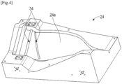
- the mold 26 advantageously comprises housings 34 provided to receive the strips 22.
- housings 34 can be recesses or recesses formed in the wall 26a, 28a opening into the cavity 30. They are advantageously calibrated to the nominal thickness of the strips 22, which is for example between 0.1 and 1.5mm.
Landscapes
- Engineering & Computer Science (AREA)
- Mechanical Engineering (AREA)
- Chemical & Material Sciences (AREA)
- General Engineering & Computer Science (AREA)
- Materials Engineering (AREA)
- Composite Materials (AREA)
- Structures Of Non-Positive Displacement Pumps (AREA)
- Casting Or Compression Moulding Of Plastics Or The Like (AREA)
- Turbine Rotor Nozzle Sealing (AREA)
- Moulding By Coating Moulds (AREA)
Claims (7)
- Schaufel (10) eines Turbotriebwerks, wobei diese Schaufel aus einem Verbundmaterial besteht, das aus dreidimensional verwobenen und in einem polymerisierten Harz getauchten Kohlefasern gebildet ist, wobei diese Schaufel einen Fuß (16) umfasst, der über einen Steg (14) mit einem Blatt (12) verbunden ist, das eine Druckseite (18) und eine Saugseite (20) und mindestens eine verschleißhemmende Gewebebahn (22), die sich auf einer Fläche des Fußes und/oder des Stegs befindet, umfasst, dadurch gekennzeichnet, dass die mindestens eine verschleißhemmende Bahn durch das Harz fest mit der Fläche des Fußes auf einheitlicher Weise zu dieser verbunden ist und durch Weben von Fasern aus PTFE und/oder Aramid hergestellt ist.
- Schaufel (10) nach Anspruch 1, wobei sie mindestens eine, und vorzugsweise zwei verschleißhemmende Bahn(en) (22) auf einer ersten Fläche des Fußes (16) und/oder des Stegs (14), die sich auf der Seite der Druckseite (18) befindet, und mindestens eine, und vorzugsweise zwei verschleißhemmende Bahn(en) auf einer zweiten Fläche des Fußes und/oder des Stegs, die sich auf der Seite der Saugseite (20) befindet, umfasst.
- Schaufel (10) nach Anspruch 1 oder 2, wobei die mindestens eine verschleißhemmende Bahn (22) eine längliche Form aufweist und sich im Wesentlichen von einem Ende des Fußes, das sich auf der Seite einer Angriffskante (12a) des Blatts (12) befindet, zu einem gegenüberliegenden Ende des Fußes, das sich auf der Seite einer Abströmkante (12b) des Blatts befindet, erstreckt.
- Schaufel (10) nach einem der vorstehenden Ansprüche, wobei die mindestens eine Bahn (22) eine Dicke aufweist, die über ihre Länge schwankt.
- Verfahren zum Herstellen einer Schaufel (10) nach einem der vorstehenden Ansprüche mittels eines Werkzeugs (24), das eine Form (26) umfasst, die einen Hohlraum (30) definiert, der konfiguriert ist, um eine Vorform (32) aus gewobenen Fasern aufzunehmen, wobei dieses Verfahren die folgenden Schritte umfasst:a) Positionierung der mindestens einen verschleißhemmenden Bahn (22) auf mindestens einer Wand (26a, 28a) der Form, die zu dem Hohlraum führt,b) Installation der Vorform im Hohlraum und auf der Wand, undc) Polymerisierung des auf den Fasern der Vorform vorhandenen oder in den Hohlraum eingespritzten Harzes, wobei dieses Harz konfiguriert ist, um die Schaufel zu verfestigen und die feste Verbindung der mindestens einen verschleißhemmenden Bahn auf dieser Schaufel zu gewährleisten.
- Verfahren nach dem vorstehenden Anspruch, wobei im Schritt a) die mindestens eine verschleißhemmende Bahn (22) in einer in der Wand (26a, 28a) gebildeten Aussparung (34) positioniert ist.
- Verfahren nach Anspruch 5 oder 6, wobei im Schritt c) das Harz konfiguriert ist, um die mindestens eine verschleißhemmende Bahn (22) zu durchnässen.
Applications Claiming Priority (2)
| Application Number | Priority Date | Filing Date | Title |
|---|---|---|---|
| FR2003301A FR3108940B1 (fr) | 2020-04-02 | 2020-04-02 | Aube composite de turbomachine et son procede de fabrication |
| PCT/FR2021/050576 WO2021198621A1 (fr) | 2020-04-02 | 2021-04-01 | Aube composite de turbomachine et son procede de fabrication |
Publications (2)
| Publication Number | Publication Date |
|---|---|
| EP4127410A1 EP4127410A1 (de) | 2023-02-08 |
| EP4127410B1 true EP4127410B1 (de) | 2024-08-07 |
Family
ID=70614322
Family Applications (1)
| Application Number | Title | Priority Date | Filing Date |
|---|---|---|---|
| EP21722277.7A Active EP4127410B1 (de) | 2020-04-02 | 2021-04-01 | Turbomaschinenverbundschaufel und verfahren zur herstellung davon |
Country Status (5)
| Country | Link |
|---|---|
| US (1) | US12000295B2 (de) |
| EP (1) | EP4127410B1 (de) |
| CN (1) | CN115485455B (de) |
| FR (1) | FR3108940B1 (de) |
| WO (1) | WO2021198621A1 (de) |
Families Citing this family (3)
| Publication number | Priority date | Publication date | Assignee | Title |
|---|---|---|---|---|
| FR3135487A1 (fr) * | 2022-05-16 | 2023-11-17 | Safran Aircraft Engines | Aube pour une turbomachine comprenant une protection anti-usure |
| FR3139493B1 (fr) * | 2022-09-14 | 2024-09-06 | Safran Aircraft Engines | Texture fibreuse de pied d’aube ou d’helice |
| FR3154637B1 (fr) * | 2023-10-30 | 2025-10-17 | Safran Aircraft Engines | Outillage de collage d’une bande anti-usure sur une aube de turbomachine |
Family Cites Families (9)
| Publication number | Priority date | Publication date | Assignee | Title |
|---|---|---|---|---|
| US5573377A (en) * | 1995-04-21 | 1996-11-12 | General Electric Company | Assembly of a composite blade root and a rotor |
| US5935360A (en) * | 1997-09-24 | 1999-08-10 | General Electric Company | Method for repairing a strip bonded to an article surface |
| US10273816B2 (en) * | 2013-02-12 | 2019-04-30 | United Technologies Corporation | Wear pad to prevent cracking of fan blade |
| US10487670B2 (en) * | 2013-03-13 | 2019-11-26 | Rolls-Royce Corporation | Gas turbine engine component including a compliant layer |
| US10774660B2 (en) * | 2013-10-14 | 2020-09-15 | Raytheon Technologies Corporation | Blade wedge attachment lay-up |
| FR3049305B1 (fr) * | 2016-03-24 | 2018-03-16 | Safran Aircraft Engines | Procede de fabrication d'une aube de turbomachine et aube obtenue par un tel procede |
| EP3406778B1 (de) * | 2017-05-22 | 2022-04-13 | Ratier-Figeac SAS | Verfahren zur herstellung einer verbundwerkstoffflugzeugschaufel |
| US11014857B2 (en) * | 2017-09-20 | 2021-05-25 | General Electric Company | Contact interface for a composite component and methods of fabrication |
| GB202002429D0 (en) * | 2020-02-21 | 2020-04-08 | Rolls Royce Plc | A fixing apparatus |
-
2020
- 2020-04-02 FR FR2003301A patent/FR3108940B1/fr active Active
-
2021
- 2021-04-01 WO PCT/FR2021/050576 patent/WO2021198621A1/fr not_active Ceased
- 2021-04-01 EP EP21722277.7A patent/EP4127410B1/de active Active
- 2021-04-01 US US17/907,573 patent/US12000295B2/en active Active
- 2021-04-01 CN CN202180032147.7A patent/CN115485455B/zh active Active
Also Published As
| Publication number | Publication date |
|---|---|
| CN115485455A (zh) | 2022-12-16 |
| FR3108940A1 (fr) | 2021-10-08 |
| EP4127410A1 (de) | 2023-02-08 |
| WO2021198621A1 (fr) | 2021-10-07 |
| US20230142441A1 (en) | 2023-05-11 |
| FR3108940B1 (fr) | 2023-03-17 |
| CN115485455B (zh) | 2025-09-12 |
| US12000295B2 (en) | 2024-06-04 |
Similar Documents
| Publication | Publication Date | Title |
|---|---|---|
| EP3776682B1 (de) | Verfahren zur herstellung einer schaufel aus verbundwerkstoff mit einer metallischen vorderkante für eine gasturbine | |
| EP2869985B1 (de) | Verfahren zum befestigen einer metallstrukturverstärkung an einem teil einer gasturbinenschaufel und spritzgiessform zur durchführung solch eines verfahrens | |
| EP4048466A1 (de) | Verfahren zum herstellen einer verbundmaterialschaufel mit angesetzter metallischer vorderkante | |
| EP4127410A1 (de) | Turbomaschinenverbundschaufel und verfahren zur herstellung davon | |
| WO2022106774A1 (fr) | Aube composite pour une turbomachine d'aéronef et son procédé de fabrication | |
| WO2021105600A1 (fr) | Aube composite pour un moteur d'aeronef et ses procedes de fabrication et de reparation | |
| WO2016030613A1 (fr) | Aube de redresseur en matériau composite pour moteur a turbine a gaz et son procédé de fabrication. | |
| FR2951400A1 (fr) | Piece structurale en materiau composite renforcee localement et procede de realisation d'une telle piece | |
| FR3049305A1 (fr) | Procede de fabrication d'une aube de turbomachine et aube obtenue par un tel procede | |
| EP4028248B1 (de) | Verfahren zur herstellung eines hohlteils und ein solches hohlteil | |
| FR3049002A1 (fr) | Pale de turbomachine aeronautique comprenant un element rapporte en materiau composite formant bord de fuite et procede de fabrication d'une telle pale | |
| FR2625528A1 (fr) | Aube monobloc composite fibre-resine pour turbomachine et procede pour sa fabrication | |
| WO2023026012A1 (fr) | Procédé de fabrication d'une aube composite de turbomachine | |
| EP3877160B1 (de) | Aushärtform zur herstellung einer aus verbundstoffmaterial aus einer vorform gefertigten turbomaschinenkomponente und verfahren zur herstellung einer komponente mittels solch einer form | |
| FR3132459A1 (fr) | Procédé de réalisation d’une pièce en matériau thermoplastique | |
| FR3061070A1 (fr) | Procede de realisation d’un panneau auto raidi en materiaux composites et panneau obtenu par ledit procede | |
| EP3233439B1 (de) | Verfahren zur herstellung der überlegformung einer verbundwerkstoffvorform | |
| FR3159764A1 (fr) | Procédé de formage et d’assemblage par drapage d’une pièce 2D sur une pièce 3D | |
| EP4405568A1 (de) | Verfahren zur herstellung eines schaufelfusses einer turbomaschinenschaufel | |
| FR3124423A1 (fr) | Procede de reparation d’une aube composite de turbomachine | |
| WO2026038005A1 (fr) | Reparation de pieces en materiau composite recouvert d'un film anti-erosion | |
| WO2025133495A1 (fr) | Pièce avec des portions de comblement | |
| WO2024156968A1 (fr) | Anneau d'ecartement en materiau composite et son procede de fabrication | |
| WO2026052909A1 (fr) | Procede de fabrication d'une aube creuse ou d'une pale d'helice creuse en materiau composite a matrice organique | |
| FR3163598A1 (fr) | Procédé pour la réalisation d’un accrochage du premier pli en drapage composite thermoplastique |
Legal Events
| Date | Code | Title | Description |
|---|---|---|---|
| STAA | Information on the status of an ep patent application or granted ep patent |
Free format text: STATUS: UNKNOWN |
|
| STAA | Information on the status of an ep patent application or granted ep patent |
Free format text: STATUS: THE INTERNATIONAL PUBLICATION HAS BEEN MADE |
|
| PUAI | Public reference made under article 153(3) epc to a published international application that has entered the european phase |
Free format text: ORIGINAL CODE: 0009012 |
|
| STAA | Information on the status of an ep patent application or granted ep patent |
Free format text: STATUS: REQUEST FOR EXAMINATION WAS MADE |
|
| 17P | Request for examination filed |
Effective date: 20221024 |
|
| AK | Designated contracting states |
Kind code of ref document: A1 Designated state(s): AL AT BE BG CH CY CZ DE DK EE ES FI FR GB GR HR HU IE IS IT LI LT LU LV MC MK MT NL NO PL PT RO RS SE SI SK SM TR |
|
| DAV | Request for validation of the european patent (deleted) | ||
| DAX | Request for extension of the european patent (deleted) | ||
| GRAP | Despatch of communication of intention to grant a patent |
Free format text: ORIGINAL CODE: EPIDOSNIGR1 |
|
| STAA | Information on the status of an ep patent application or granted ep patent |
Free format text: STATUS: GRANT OF PATENT IS INTENDED |
|
| INTG | Intention to grant announced |
Effective date: 20240507 |
|
| GRAS | Grant fee paid |
Free format text: ORIGINAL CODE: EPIDOSNIGR3 |
|
| GRAA | (expected) grant |
Free format text: ORIGINAL CODE: 0009210 |
|
| STAA | Information on the status of an ep patent application or granted ep patent |
Free format text: STATUS: THE PATENT HAS BEEN GRANTED |
|
| AK | Designated contracting states |
Kind code of ref document: B1 Designated state(s): AL AT BE BG CH CY CZ DE DK EE ES FI FR GB GR HR HU IE IS IT LI LT LU LV MC MK MT NL NO PL PT RO RS SE SI SK SM TR |
|
| REG | Reference to a national code |
Ref country code: GB Ref legal event code: FG4D Free format text: NOT ENGLISH |
|
| REG | Reference to a national code |
Ref country code: CH Ref legal event code: EP |
|
| REG | Reference to a national code |
Ref country code: IE Ref legal event code: FG4D Free format text: LANGUAGE OF EP DOCUMENT: FRENCH |
|
| REG | Reference to a national code |
Ref country code: DE Ref legal event code: R096 Ref document number: 602021016834 Country of ref document: DE |
|
| REG | Reference to a national code |
Ref country code: LT Ref legal event code: MG9D |
|
| REG | Reference to a national code |
Ref country code: NL Ref legal event code: MP Effective date: 20240807 |
|
| PG25 | Lapsed in a contracting state [announced via postgrant information from national office to epo] |
Ref country code: NO Free format text: LAPSE BECAUSE OF FAILURE TO SUBMIT A TRANSLATION OF THE DESCRIPTION OR TO PAY THE FEE WITHIN THE PRESCRIBED TIME-LIMIT Effective date: 20241107 |
|
| REG | Reference to a national code |
Ref country code: AT Ref legal event code: MK05 Ref document number: 1711150 Country of ref document: AT Kind code of ref document: T Effective date: 20240807 |
|
| PG25 | Lapsed in a contracting state [announced via postgrant information from national office to epo] |
Ref country code: GR Free format text: LAPSE BECAUSE OF FAILURE TO SUBMIT A TRANSLATION OF THE DESCRIPTION OR TO PAY THE FEE WITHIN THE PRESCRIBED TIME-LIMIT Effective date: 20241108 Ref country code: NL Free format text: LAPSE BECAUSE OF FAILURE TO SUBMIT A TRANSLATION OF THE DESCRIPTION OR TO PAY THE FEE WITHIN THE PRESCRIBED TIME-LIMIT Effective date: 20240807 Ref country code: PL Free format text: LAPSE BECAUSE OF FAILURE TO SUBMIT A TRANSLATION OF THE DESCRIPTION OR TO PAY THE FEE WITHIN THE PRESCRIBED TIME-LIMIT Effective date: 20240807 Ref country code: FI Free format text: LAPSE BECAUSE OF FAILURE TO SUBMIT A TRANSLATION OF THE DESCRIPTION OR TO PAY THE FEE WITHIN THE PRESCRIBED TIME-LIMIT Effective date: 20240807 Ref country code: PT Free format text: LAPSE BECAUSE OF FAILURE TO SUBMIT A TRANSLATION OF THE DESCRIPTION OR TO PAY THE FEE WITHIN THE PRESCRIBED TIME-LIMIT Effective date: 20241209 |
|
| PG25 | Lapsed in a contracting state [announced via postgrant information from national office to epo] |
Ref country code: BG Free format text: LAPSE BECAUSE OF FAILURE TO SUBMIT A TRANSLATION OF THE DESCRIPTION OR TO PAY THE FEE WITHIN THE PRESCRIBED TIME-LIMIT Effective date: 20240807 |
|
| PG25 | Lapsed in a contracting state [announced via postgrant information from national office to epo] |
Ref country code: LV Free format text: LAPSE BECAUSE OF FAILURE TO SUBMIT A TRANSLATION OF THE DESCRIPTION OR TO PAY THE FEE WITHIN THE PRESCRIBED TIME-LIMIT Effective date: 20240807 |
|
| PG25 | Lapsed in a contracting state [announced via postgrant information from national office to epo] |
Ref country code: AT Free format text: LAPSE BECAUSE OF FAILURE TO SUBMIT A TRANSLATION OF THE DESCRIPTION OR TO PAY THE FEE WITHIN THE PRESCRIBED TIME-LIMIT Effective date: 20240807 Ref country code: IS Free format text: LAPSE BECAUSE OF FAILURE TO SUBMIT A TRANSLATION OF THE DESCRIPTION OR TO PAY THE FEE WITHIN THE PRESCRIBED TIME-LIMIT Effective date: 20241207 |
|
| PG25 | Lapsed in a contracting state [announced via postgrant information from national office to epo] |
Ref country code: HR Free format text: LAPSE BECAUSE OF FAILURE TO SUBMIT A TRANSLATION OF THE DESCRIPTION OR TO PAY THE FEE WITHIN THE PRESCRIBED TIME-LIMIT Effective date: 20240807 |
|
| PG25 | Lapsed in a contracting state [announced via postgrant information from national office to epo] |
Ref country code: RS Free format text: LAPSE BECAUSE OF FAILURE TO SUBMIT A TRANSLATION OF THE DESCRIPTION OR TO PAY THE FEE WITHIN THE PRESCRIBED TIME-LIMIT Effective date: 20241107 Ref country code: ES Free format text: LAPSE BECAUSE OF FAILURE TO SUBMIT A TRANSLATION OF THE DESCRIPTION OR TO PAY THE FEE WITHIN THE PRESCRIBED TIME-LIMIT Effective date: 20240807 |
|
| PG25 | Lapsed in a contracting state [announced via postgrant information from national office to epo] |
Ref country code: RS Free format text: LAPSE BECAUSE OF FAILURE TO SUBMIT A TRANSLATION OF THE DESCRIPTION OR TO PAY THE FEE WITHIN THE PRESCRIBED TIME-LIMIT Effective date: 20241107 Ref country code: PT Free format text: LAPSE BECAUSE OF FAILURE TO SUBMIT A TRANSLATION OF THE DESCRIPTION OR TO PAY THE FEE WITHIN THE PRESCRIBED TIME-LIMIT Effective date: 20241209 Ref country code: PL Free format text: LAPSE BECAUSE OF FAILURE TO SUBMIT A TRANSLATION OF THE DESCRIPTION OR TO PAY THE FEE WITHIN THE PRESCRIBED TIME-LIMIT Effective date: 20240807 Ref country code: NO Free format text: LAPSE BECAUSE OF FAILURE TO SUBMIT A TRANSLATION OF THE DESCRIPTION OR TO PAY THE FEE WITHIN THE PRESCRIBED TIME-LIMIT Effective date: 20241107 Ref country code: NL Free format text: LAPSE BECAUSE OF FAILURE TO SUBMIT A TRANSLATION OF THE DESCRIPTION OR TO PAY THE FEE WITHIN THE PRESCRIBED TIME-LIMIT Effective date: 20240807 Ref country code: LV Free format text: LAPSE BECAUSE OF FAILURE TO SUBMIT A TRANSLATION OF THE DESCRIPTION OR TO PAY THE FEE WITHIN THE PRESCRIBED TIME-LIMIT Effective date: 20240807 Ref country code: IS Free format text: LAPSE BECAUSE OF FAILURE TO SUBMIT A TRANSLATION OF THE DESCRIPTION OR TO PAY THE FEE WITHIN THE PRESCRIBED TIME-LIMIT Effective date: 20241207 Ref country code: HR Free format text: LAPSE BECAUSE OF FAILURE TO SUBMIT A TRANSLATION OF THE DESCRIPTION OR TO PAY THE FEE WITHIN THE PRESCRIBED TIME-LIMIT Effective date: 20240807 Ref country code: GR Free format text: LAPSE BECAUSE OF FAILURE TO SUBMIT A TRANSLATION OF THE DESCRIPTION OR TO PAY THE FEE WITHIN THE PRESCRIBED TIME-LIMIT Effective date: 20241108 Ref country code: FI Free format text: LAPSE BECAUSE OF FAILURE TO SUBMIT A TRANSLATION OF THE DESCRIPTION OR TO PAY THE FEE WITHIN THE PRESCRIBED TIME-LIMIT Effective date: 20240807 Ref country code: ES Free format text: LAPSE BECAUSE OF FAILURE TO SUBMIT A TRANSLATION OF THE DESCRIPTION OR TO PAY THE FEE WITHIN THE PRESCRIBED TIME-LIMIT Effective date: 20240807 Ref country code: BG Free format text: LAPSE BECAUSE OF FAILURE TO SUBMIT A TRANSLATION OF THE DESCRIPTION OR TO PAY THE FEE WITHIN THE PRESCRIBED TIME-LIMIT Effective date: 20240807 Ref country code: AT Free format text: LAPSE BECAUSE OF FAILURE TO SUBMIT A TRANSLATION OF THE DESCRIPTION OR TO PAY THE FEE WITHIN THE PRESCRIBED TIME-LIMIT Effective date: 20240807 |
|
| PG25 | Lapsed in a contracting state [announced via postgrant information from national office to epo] |
Ref country code: SM Free format text: LAPSE BECAUSE OF FAILURE TO SUBMIT A TRANSLATION OF THE DESCRIPTION OR TO PAY THE FEE WITHIN THE PRESCRIBED TIME-LIMIT Effective date: 20240807 Ref country code: DK Free format text: LAPSE BECAUSE OF FAILURE TO SUBMIT A TRANSLATION OF THE DESCRIPTION OR TO PAY THE FEE WITHIN THE PRESCRIBED TIME-LIMIT Effective date: 20240807 |
|
| PG25 | Lapsed in a contracting state [announced via postgrant information from national office to epo] |
Ref country code: EE Free format text: LAPSE BECAUSE OF FAILURE TO SUBMIT A TRANSLATION OF THE DESCRIPTION OR TO PAY THE FEE WITHIN THE PRESCRIBED TIME-LIMIT Effective date: 20240807 |
|
| PG25 | Lapsed in a contracting state [announced via postgrant information from national office to epo] |
Ref country code: CZ Free format text: LAPSE BECAUSE OF FAILURE TO SUBMIT A TRANSLATION OF THE DESCRIPTION OR TO PAY THE FEE WITHIN THE PRESCRIBED TIME-LIMIT Effective date: 20240807 |
|
| PG25 | Lapsed in a contracting state [announced via postgrant information from national office to epo] |
Ref country code: SK Free format text: LAPSE BECAUSE OF FAILURE TO SUBMIT A TRANSLATION OF THE DESCRIPTION OR TO PAY THE FEE WITHIN THE PRESCRIBED TIME-LIMIT Effective date: 20240807 |
|
| REG | Reference to a national code |
Ref country code: DE Ref legal event code: R097 Ref document number: 602021016834 Country of ref document: DE |
|
| PLBE | No opposition filed within time limit |
Free format text: ORIGINAL CODE: 0009261 |
|
| STAA | Information on the status of an ep patent application or granted ep patent |
Free format text: STATUS: NO OPPOSITION FILED WITHIN TIME LIMIT |
|
| PGFP | Annual fee paid to national office [announced via postgrant information from national office to epo] |
Ref country code: DE Payment date: 20250417 Year of fee payment: 5 |
|
| 26N | No opposition filed |
Effective date: 20250508 |
|
| PGFP | Annual fee paid to national office [announced via postgrant information from national office to epo] |
Ref country code: FR Payment date: 20250428 Year of fee payment: 5 |
|
| PG25 | Lapsed in a contracting state [announced via postgrant information from national office to epo] |
Ref country code: SE Free format text: LAPSE BECAUSE OF FAILURE TO SUBMIT A TRANSLATION OF THE DESCRIPTION OR TO PAY THE FEE WITHIN THE PRESCRIBED TIME-LIMIT Effective date: 20240807 |
|
| REG | Reference to a national code |
Ref country code: CH Ref legal event code: H13 Free format text: ST27 STATUS EVENT CODE: U-0-0-H10-H13 (AS PROVIDED BY THE NATIONAL OFFICE) Effective date: 20251125 |
|
| PG25 | Lapsed in a contracting state [announced via postgrant information from national office to epo] |
Ref country code: LU Free format text: LAPSE BECAUSE OF NON-PAYMENT OF DUE FEES Effective date: 20250401 |
|
| PG25 | Lapsed in a contracting state [announced via postgrant information from national office to epo] |
Ref country code: MC Free format text: LAPSE BECAUSE OF FAILURE TO SUBMIT A TRANSLATION OF THE DESCRIPTION OR TO PAY THE FEE WITHIN THE PRESCRIBED TIME-LIMIT Effective date: 20240807 |
|
| REG | Reference to a national code |
Ref country code: BE Ref legal event code: MM Effective date: 20250430 |
|
| PG25 | Lapsed in a contracting state [announced via postgrant information from national office to epo] |
Ref country code: BE Free format text: LAPSE BECAUSE OF NON-PAYMENT OF DUE FEES Effective date: 20250430 |
|
| PG25 | Lapsed in a contracting state [announced via postgrant information from national office to epo] |
Ref country code: CH Free format text: LAPSE BECAUSE OF NON-PAYMENT OF DUE FEES Effective date: 20250430 |
|
| PG25 | Lapsed in a contracting state [announced via postgrant information from national office to epo] |
Ref country code: IT Free format text: LAPSE BECAUSE OF FAILURE TO SUBMIT A TRANSLATION OF THE DESCRIPTION OR TO PAY THE FEE WITHIN THE PRESCRIBED TIME-LIMIT Effective date: 20240807 |
|
| PGFP | Annual fee paid to national office [announced via postgrant information from national office to epo] |
Ref country code: GB Payment date: 20260327 Year of fee payment: 6 |
|
| PG25 | Lapsed in a contracting state [announced via postgrant information from national office to epo] |
Ref country code: IE Free format text: LAPSE BECAUSE OF NON-PAYMENT OF DUE FEES Effective date: 20250401 |
|
| PG25 | Lapsed in a contracting state [announced via postgrant information from national office to epo] |
Ref country code: RO Free format text: LAPSE BECAUSE OF FAILURE TO SUBMIT A TRANSLATION OF THE DESCRIPTION OR TO PAY THE FEE WITHIN THE PRESCRIBED TIME-LIMIT Effective date: 20240807 |