EP4127301B1 - Regenerierbares system und verfahren zum filtern von mikrofasern aus einer abfallflüssigkeit - Google Patents
Regenerierbares system und verfahren zum filtern von mikrofasern aus einer abfallflüssigkeit Download PDFInfo
- Publication number
- EP4127301B1 EP4127301B1 EP21713411.3A EP21713411A EP4127301B1 EP 4127301 B1 EP4127301 B1 EP 4127301B1 EP 21713411 A EP21713411 A EP 21713411A EP 4127301 B1 EP4127301 B1 EP 4127301B1
- Authority
- EP
- European Patent Office
- Prior art keywords
- granular medium
- liquid effluent
- enclosure
- fluidization
- granular
- Prior art date
- Legal status (The legal status is an assumption and is not a legal conclusion. Google has not performed a legal analysis and makes no representation as to the accuracy of the status listed.)
- Active
Links
Images


Classifications
-
- D—TEXTILES; PAPER
- D06—TREATMENT OF TEXTILES OR THE LIKE; LAUNDERING; FLEXIBLE MATERIALS NOT OTHERWISE PROVIDED FOR
- D06F—LAUNDERING, DRYING, IRONING, PRESSING OR FOLDING TEXTILE ARTICLES
- D06F39/00—Details of washing machines not specific to a single type of machines covered by groups D06F9/00 - D06F27/00
- D06F39/10—Filtering arrangements
-
- B—PERFORMING OPERATIONS; TRANSPORTING
- B01—PHYSICAL OR CHEMICAL PROCESSES OR APPARATUS IN GENERAL
- B01D—SEPARATION
- B01D24/00—Filters comprising loose filtering material, i.e. filtering material without any binder between the individual particles or fibres thereof
- B01D24/02—Filters comprising loose filtering material, i.e. filtering material without any binder between the individual particles or fibres thereof with the filter bed stationary during the filtration
- B01D24/10—Filters comprising loose filtering material, i.e. filtering material without any binder between the individual particles or fibres thereof with the filter bed stationary during the filtration the filtering material being held in a closed container
- B01D24/12—Downward filtration, the filtering material being supported by pervious surfaces
-
- B—PERFORMING OPERATIONS; TRANSPORTING
- B01—PHYSICAL OR CHEMICAL PROCESSES OR APPARATUS IN GENERAL
- B01D—SEPARATION
- B01D24/00—Filters comprising loose filtering material, i.e. filtering material without any binder between the individual particles or fibres thereof
- B01D24/46—Regenerating the filtering material in the filter
- B01D24/4631—Counter-current flushing, e.g. by air
-
- D—TEXTILES; PAPER
- D06—TREATMENT OF TEXTILES OR THE LIKE; LAUNDERING; FLEXIBLE MATERIALS NOT OTHERWISE PROVIDED FOR
- D06F—LAUNDERING, DRYING, IRONING, PRESSING OR FOLDING TEXTILE ARTICLES
- D06F33/00—Control of operations performed in washing machines or washer-dryers
- D06F33/30—Control of washing machines characterised by the purpose or target of the control
- D06F33/32—Control of operational steps, e.g. optimisation or improvement of operational steps depending on the condition of the laundry
- D06F33/42—Control of operational steps, e.g. optimisation or improvement of operational steps depending on the condition of the laundry of draining
Definitions
- the present invention relates to the field of eliminating microfibers contained in a drain liquid of a textile treatment device, such as a washing machine, a laundromat (industrial or not), a device for dyeing clothes. textiles, or even a device for waterproofing textiles.
- a textile treatment device such as a washing machine, a laundromat (industrial or not), a device for dyeing clothes. textiles, or even a device for waterproofing textiles.
- microfibers from synthetic clothing are microfibers from synthetic clothing. These microplastics are mainly released when washing synthetic textiles in the form of microfibers, due to abrasion of the fabrics during the wash cycle. More than 700,000 microscopic fibers can thus be released into wastewater during each use of a domestic washing machine, with many likely to pass through wastewater treatment and therefore end up in the environment.
- the quantity of fibers released during the washing of textiles corresponds to a quantity varying from 0.005 to 0.02% of the weight of the washed textiles depending on the nature of the textile.
- France passed a law relating to the fight against waste and the circular economy in which article 10 bis AAB provides that new washing machines must be equipped with a filter.
- plastic microfibers from January 1, 2025. France is the first country in the world to take such a measure.
- the patent application WO 2019/017848 describes a system for retaining microfibers, to be positioned at the outlet of a washing machine, based on microfiltration membranes made of polyethylene nanofibers.
- the membrane has a preferred pore diameter of around 50 ⁇ m and is optionally doped with aluminum oxide nanoparticles to improve the adsorption of microfibers.
- the filter membrane described in this document has a certain mobility, which allows it to have an anti-clogging function.
- the cartridge containing the micro-filtration membrane marketed to date has a lifespan of 20 washing cycles. The use of such a filter therefore requires a significant quantity of consumables, and therefore a significant consumption of plastic materials to manufacture them.
- the plastic nanofibers constituting the membrane may present a risk of deterioration during use, and therefore of release into wastewater.
- the present invention relates to a system and a method for filtering microfibers (plastic or other) at the outlet of textile treatment devices, in an efficient, inexpensive manner and requiring few consumables.
- the system according to the invention can be regenerable, which makes it possible to strongly limit the periodicity of the according to the invention can also allow the collection of at least part of the microfibers leaving a textile treatment device, for possible subsequent recycling.
- said means of connection to said means of regeneration by fluidization of said granular medium may comprise an additional opening arranged in said enclosure and disposed under said support of said granular medium, said additional opening of said connection means being suitable to be connected to means for admission of a gas and/or for insufflation of a gas.
- said means for evacuating said liquid effluent may comprise a circuit external to said enclosure, connected to said enclosure to short-circuit said granular medium in the event of accumulation of said liquid effluent in said free volume of said enclosure above said granular medium.
- said means for evacuating said liquid effluent may comprise a pipe passing through at least said granular medium to short-circuit said granular medium in the event of an accumulation of said liquid effluent in said free volume of said enclosure above said granular medium, said pipe being preferably provided with a deflector in its upper part.
- said external circuit (140) to said enclosure may further comprise a liquid detector, preferably connected to an alarm.
- said pipe (140) of said evacuation means (110) of said liquid effluent may further comprise a liquid detector, preferably connected to an alarm.
- said system may further comprise means for controlling said means for passing by percolation of said liquid effluent through said granular medium and/or said means for evacuating said liquid effluent, and/or said means of connection to said means of regeneration by fluidization of said granular medium.
- said control means may comprise at least one 2-way valve, and/or at least one 3-way valve, and/or at least one non-return valve, and/or a valve 6 rotary tracks.
- said system may further comprise a settling chamber and/or a cyclonic separation chamber and/or a chamber for accumulating said liquid effluent, arranged upstream of said enclosure, and connected to said means for passing said liquid effluent by percolation through said granular medium.
- said system may further comprise means for injecting at least one flocculating agent into said liquid effluent, said injection means being arranged for an injection of said at least one flocculating agent into said liquid effluent upstream of said granular medium.
- said granular medium may comprise sand particles, crushed glass beads or raw glass beads, particles formed from natural or synthetic zeolite, based on alumina, or still based on resins or plastic.
- said granular medium may comprise particles of size between 0.1 mm and 2 cm for at least 80% by weight of said particles, preferably between 0.3 and 2.5 mm for at least 90% by weight. of said particles.
- a liquid distributor can be arranged between said granular medium (30) and said opening (100) of said means (100) for the passage by percolation of said liquid effluent through said granular medium (30).
- a gas distributor can be placed between said granular medium (30) and an opening intended for the admission of the gas said gas suction means.
- step A) can be repeated between 50 and 150 times, preferably approximately 100 times, before carrying out step B).
- said method may comprise, prior to step A), a step of pretreatment of said liquid effluent, said step of pretreatment of said liquid effluent comprising at least one injection of at least one flocculating agent in said liquid effluent and/or at least one decantation of said liquid effluent and/or at least one cyclonic separation of said liquid effluent.
- said method may comprise, prior to step B), a phase of drainage of said granular medium, carried out by means of gaseous suction means connected to said system so as to generate a downward flow of gas through said granular medium, and/or a drying phase of said granular medium, carried out by means of means for increasing the temperature of said granular medium.
- said filtration and regeneration phases can be controlled by means of said control means of said system for the filtration of microfibers as described above.
- said method may further comprise at least one step subsequent to said regeneration phase by fluidization, consisting of the collection of said microfibers resulting from said regeneration phase, preferably by means of a chamber cyclonic and/or a membrane filter arranged downstream of said means for regenerating said granular medium by fluidization.
- the invention also relates to a textile washing device, comprising at least one system for the filtration of microfibers contained in a liquid effluent according to any of the embodiments described above
- the invention relates to a system and a method for the filtration of microfibers contained in a liquid effluent from a textile treatment device.
- microfibers we mean particles from woven or knitted materials, composed of natural fibers (cotton, wool, etc.) or synthetic fibers (polyester, polyamide, acrylic, etc.) such as clothing or fabrics used in the clothing or for any other application (for example sheets, curtains, etc.) in private homes or in industry.
- Microfibers normally entrained in washing machine drain water, are generally elongated in shape, with diameters generally between 0.1 and 50 microns. The length of the fibers can range from a few fiber diameters up to several mm depending on the nature and condition of the materials that are washed upstream.
- a textile treatment device in particular a textile washing device, for example an individual laundry washing machine, for domestic or commercial use, a set of laundry washing machines (for example in laundries ), an industrial laundry (e.g. laundry) etc.
- a textile treatment device according to the invention generally comprises any device bringing a textile into contact with a liquid, the liquid then being separated from the textile, such as a device for dyeing a textile, or even a device for waterproofing a textile.
- liquid effluent from at least one textile treatment device we mean the liquid resulting from draining (for example the liquid after washing and/or rinsing and/or spinning in the case of a textile washing device) of a textile treatment device.
- drain fluid we subsequently speak equivalently of "drain fluid”.
- the microfiber load in liquid effluents leaving textile treatment devices is generally limited, with contents between 0.1 and 1000 ppm by weight, generally between 1 and 100 ppm by weight.
- the system according to the invention is intended to be connected to a pipe for emptying a textile treatment device.
- the system according to the invention can either be installed outside a textile treatment device (at the end of the pipe for emptying the textile treatment device) or inside a textile treatment device. textile treatment (on a portion of the pipe for emptying the textile treatment device).
- the general principle of the filtration system according to the invention consists of the filtration of microfibers contained in a liquid effluent coming from a textile treatment device, by percolation of this liquid effluent through a granular medium located in an enclosure .
- the system according to the invention can advantageously be connected to means of regeneration by fluidization of the granular medium, to eliminate the microfibers having deposited in the granular medium.
- the method according to the invention generally comprises at least one step of filtering the microfibers contained in a liquid effluent from a textile treatment device, by percolation of this liquid effluent through a granular medium located in a enclosure, followed by a regeneration step by fluidization of the granular medium.
- the regeneration phase is carried out by means of an ascending flow of a gas through the granular medium, the ascending gas preferably being air.
- the system according to the invention comprises an enclosure, in which a portion of the space is occupied by a granular medium, this granular medium being overcome by a free volume in the enclosure.
- the granular medium is arranged on at least one support permeable at least to the liquid effluent, and consequently to gases in general (that is to say to all gases), in particular to gas which can be used for the regeneration of the granular medium by fluidization using a gas as will be described below.
- the support of the granular medium can be a grid, the meshes of which are sized to retain the granular medium while allowing the passage of at least the liquid effluent.
- the enclosure can be cylindrical or parallelepiped in shape, and is preferably elongated along the axis of the flow of the liquid effluent passing through the enclosure (that is to say along a vertical axis as will be described below ).
- the section of the enclosure can be constant along the part of the enclosure in contact with the granular medium, and the section can be larger, or even increasing, in the part of the enclosure located above the granular medium.
- the free volume above the granular medium is thus increased, which on the one hand makes it possible to avoid the risk of backflow of the liquid effluent in the event of accumulation above the granular medium (which can occur in the event of clogging of the granular medium), and on the other hand to improve the regeneration of the granular medium, by increasing the volume available for expansion by fluidization of the granular medium and by lowering the speed of the regeneration fluid above the granular medium (which limits the entrainment of particles from the granular medium).
- the granular medium according to the invention comprises at least one bed of particles as will be described below.
- the system according to the invention further comprises means for the passage by percolation of the liquid effluent through the granular medium.
- the granular medium is crossed by a vertical flow, from top to bottom, of the liquid effluent.
- This is made possible in the system according to the invention by at least one opening for the passage of the liquid effluent provided in the upper part of the enclosure, above the granular medium.
- the term "upper part” is taken with reference to the direction of the flow of the liquid effluent through the enclosure, from top to bottom.
- the opening of the means for the passage by percolation of the liquid effluent through the granular medium is arranged in the upper wall of the enclosure of the system according to the invention, preferably in a central part of this upper wall (for example located in a zone centered on the barycenter of the upper wall, and whose radius corresponds to 30% of the smallest dimension of the upper wall).
- An opening provided in a central part of the upper wall of the enclosure allows more homogeneous distribution laterally of the liquid effluent compared to an eccentric opening.
- the system according to the invention comprises means for evacuating the liquid effluent, these evacuation means comprising at least one opening provided in the lower part of the enclosure, and under the support for the granular medium.
- evacuation means comprising at least one opening provided in the lower part of the enclosure, and under the support for the granular medium.
- the term "lower part” is taken with reference to the direction of the flow of liquid effluent through the enclosure, from top to bottom.
- this opening of the means for evacuating the liquid effluent allows an outlet of the liquid effluent filtered by the granular medium, in the lower part of the enclosure, below the support of the granular medium.
- the opening of the means for evacuating the liquid effluent is arranged in the lower wall of the enclosure of the system according to the invention, to avoid an accumulation of the filtered liquid effluent in the bottom of the enclosure.
- this opening can be connected to a wastewater evacuation system, such as a siphon upstream of a sewer system.
- a lifting pump can be implemented to ensure the evacuation of the filtered effluent.
- the system according to the invention further comprises means of connection to means of regeneration by fluidization of the granular medium, comprising at least one opening provided in the upper part of the enclosure, above the granular medium.
- the means of regeneration by fluidization of the granular medium aim to prevent clogging of the granular medium which can result from the accumulation of filtered microfibers in the granular medium.
- fluidization of a granular medium is conventionally obtained by a passage of liquid or gas from the bottom to the top through a granular medium.
- the means of regeneration by fluidization of the granular medium which can be connected to the system according to the invention are means of regeneration by gas fluidization.
- gas fluidization is meant a fluidization of the particles of the granular medium by means of a gas.
- the passage of a gas from the bottom to the top sets the particles of the granular medium in motion, which results in an expansion of the granular medium in the free volume above the granular medium, and the fibers are carried away by the gas flow. ascending.
- the system according to the invention can be connected, via the connection means according to the invention, to means for regenerating the granular medium in the form of gaseous suction means (such as a vacuum cleaner for domestic or industrial use) and/or gas insufflation means (such as air compression or overpressure systems).
- the gas used to fluidize and regenerate the granular medium can enter the system through the opening of the liquid effluent evacuation means provided in the lower part of the enclosure.
- the means of connection to the means of regeneration by fluidization of the granular medium of the system according to the invention comprise at least one opening disposed above the granular medium, in the upper part of the enclosure.
- This opening allows the evacuation of microfibers released from the granular medium by fluidization.
- this opening of the means of connection to the means of regeneration by fluidization of the granular medium is arranged in the upper wall of the enclosure of the system according to the invention, preferably in a central part of this upper wall (for example located in a zone centered on the barycenter of the upper wall, and whose radius corresponds to 30% of the smallest dimension of the upper wall).
- opening the means for the passage by percolation of the liquid effluent through the granular medium and the opening of the means of connection to means of regeneration by fluidization of the granular medium can be common, and their function either of filtration or of regeneration can then be controlled by control means such as valves comprising at least three ways.
- the opening of the means for the passage by percolation of the liquid effluent through the granular medium and the opening of the means of connection to means of regeneration by fluidization of the granular medium can be common, and their function, either filtration or regeneration, can be controlled by manual action or automatically.
- the means of regeneration by fluidization of the granular medium make it possible to extend the lifespan of the system according to the invention.
- the means for regeneration by fluidization of the granular medium are configured to eliminate the microfibers from the granular medium when the accumulated volume of microfibers represents 0.1 to 10% of the porosity of the granular medium, preferably 0.5 to 5% of the porosity of the granular medium. In this way, it is possible to carry out around a hundred regeneration phases before replacing the granular medium of the system according to the invention.
- a grid can be placed in the enclosure, between the opening of the means for the passage by percolation of the liquid effluent through the granular medium and the granular medium, the size of the openings of the grid being less than the size particles of the granular medium.
- This grid makes it possible to retain, inside the enclosure, the particles of the granular medium during regeneration by fluidization.
- such a grid can also allow a more homogeneous distribution of the liquid effluent on the granular medium, thus improving the filtration quality of the system according to the invention.
- a jet breaker can also be placed under the opening of the means for the passage by percolation of the liquid effluent through the granular medium, allowing the introduction of the liquid effluent so as to disperse it and avoid as well as a too powerful jet of liquid effluent impacting the granular medium.
- a liquid distributor can also be arranged between the opening of the means for the passage by percolation of the liquid effluent through the granular medium and the granular medium.
- a liquid dispenser allows homogeneous distribution of a liquid.
- the liquid distributor can be a perforated plate with liquid retention. Such a distributor makes it possible to evenly distribute the liquid over the section of the granular medium.
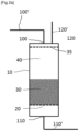
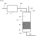
- FIG. 1 illustrates, in a schematic and non-limiting manner, a first embodiment of the system according to the invention.
- the system for the filtration of microfibers consists of a cylindrical enclosure 10 provided with a support 20 allowing to support a granular medium 30 consisting of a bed of particles, and surmounted by a free volume 40 making it possible to contain the accumulation of drain liquid during filtration and/or to contain an expansion of the particles of the bed 30 which is fluidized during regeneration.
- the system according to this embodiment comprises, in the upper wall of the enclosure 10, an opening 100 allowing the supply of the liquid effluent to be filtered, from a drain pipe 100'.
- the system according to this embodiment also comprises an opening 120 intended to be connected to means (not shown) for the regeneration by fluidization of the granular medium (for example gas suction means), via a pipe 120'.
- the system further comprises an opening 110 allowing the evacuation of the filtered liquid effluent at the base of the enclosure 10.
- This opening 110 is arranged under the granular medium 30 and under the support 20 of the granular medium, and can be connected via a pipe 110' to a wastewater evacuation system (not shown), such as a siphon upstream of a sewer system.
- FIG 2a presents a variant of the embodiment of the figure 1 , in every respect identical to this first embodiment (thus, the common elements will not be described again), with the exception of a grid 35 placed between the opening 120 for connection with the means of regeneration by fluidization (not shown) and the granular medium 30, the size of the openings of the grid 35 being smaller than the size of the particles of the granular medium 30.
- This grid 35 makes it possible to retain, inside the enclosure 10, the particles of the granular medium 30 during regeneration by fluidization.
- such a grid 35 can also allow a more homogeneous distribution of the liquid effluent on the granular medium 30 (jet breaker function), arriving through the opening 100, thus improving the filtration quality of the system according to the invention.
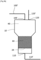
- FIG 2b presents another variant of the embodiment of the figure 1 , in every respect identical to this first mode (thus, the common elements will not be described again), with the exception of the shape of the enclosure 10 which is cylindrical in its lower part, frustoconical in an intermediate part , and cylindrical in an upper part, the section of the upper part being greater than the section of the lower part.
- This particular geometry of the enclosure 10 makes it possible to increase the free volume above the granular medium, which thus makes it possible on the one hand to avoid the risk of backflow of the liquid effluent through the two openings 100, 120 located in the upper part of the enclosure in the event of accumulation above the granular medium 30 (which can occur in the event of clogging of the granular medium) and on the other hand to improve the regeneration of the granular medium, by increasing the volume available for expansion by fluidization of the granular medium 30.
- the system and the method according to the invention allow filtration of the microfibers contained in a drain liquid, by retention of microfibers in the porosity of the granular medium passed through by the effluent.
- This type of filtration also known as "depth filtration” in other fields, is particularly suited to capturing microfibers whose elongated shape facilitates retention in the tortuosity of the bed of particles.
- part of the microfibers can also be retained on the upper surface of the granular medium.
- the system according to the invention is also capable of being connected to means for regenerating the granular medium by fluidization, making it possible to clean the filter according to the invention, and possibly collect the microfibers retained in the porosity of the granular medium.
- the granular medium according to the invention comprises at least one bed of particles, hereinafter called equivalently "filter bed” or "filtration bed".
- the granular medium can comprise a plurality of layered particle beds, each held by a support which is not impervious to at least the liquid effluent (the support will therefore also be impermeable to gases in general, and in particular to the gas used for the regeneration of the granular medium by gas fluidization).
- the liquid effluent can flow by percolation through each of the layered beds, from top to bottom.
- the material constituting the particles of a bed can be defined by its composition, but also by its particle size and its density. Different types of particles can be considered to constitute a bed of particles, as described below.
- the particles of a bed can be sand particles, or even crushed glass beads or raw glass beads, particles formed based on natural or synthetic zeolite, based alumina, or even based on resins or plastic.
- the materials cited above in fact have the advantages of being easily accessible commercially and have properties (in particular density as will be discussed below) adapted to the intended application.
- the particles of a bed can be made of a material whose surface properties have been modified to promote the retention of microfibers, by phenomena of physico-chemical affinity with the textile microfibers (by modifying the electrostatic properties particles in particular), or to limit the affinity of these particles with water (via a hydrophobic treatment, for example by covering particles such as glass beads with a Teflon film), which makes it easier to drying the bed before regeneration.
- a hydrophobic treatment for example by covering particles such as glass beads with a Teflon film
- the particle size affects the filtration and regeneration capacity of the granular medium with respect to the microfibers, by acting on the resistance to flow to fluids.
- the size of the particles can be comprised, for at least 80% by weight of the particles, between 0.1 mm and 2 cm, preferably comprised, for at least 90% by weight of the particles, between 0.3 and 2.5 mm.
- the average equivalent diameter of the particles of the granular medium (defined relative to the size distribution by weight of the particles) of the particles can be between 0.3 and 1.35 mm, and preferably between 0.4 and 0.8 mm.
- the quantity of particles having a size less than 0.1 mm can be less than 5% by weight.
- the beds can be made up of particles having decreasing particle sizes along the direction of the flow of the liquid effluent (that is to say from the top downwards), so as to allow filtration first of the larger fibers, then of increasingly finer fibers.
- This implementation is particularly indicated in the case where the retention of colloidal particles of very small sizes contained in the liquid effluent is desired.
- colloidal particles can for example be formed from pigments and additives contained in textiles and detergent constituents.
- the capture of these colloidal particles is particularly indicated in the last bed of the enclosure following the direction of the flow of the liquid effluent.
- This last bed following the direction of the liquid effluent which can be described as a finishing bed, may possibly not be connected to regeneration means and may be subject to periodic replacement.
- the density of the particles constituting a bed of particles affects the fluidization of the particles during regeneration (minimum speed allowing fluidization of the bed and pressure loss across the bed).
- the materials described above to constitute particles for example sand, glass, zeolite
- the materials described above to constitute particles generally have grain densities of between 1100 and 2800 kg/m 2 suitable for regeneration for example by gas suction, even when the suction flow is moderate (for example with a domestic vacuum cleaner).
- hollow materials such as hollow glass or plastic beads can be used, the grain density of which can be lower, which then makes it possible to regenerate the bed with lower fluid flow rates.
- the speed of passage of the liquid effluent in a bed of particles influences on the one hand the quality with which fiber retention is achieved and on the other hand on the pressure loss of the liquid effluent through the bed of particles.
- the system according to the invention can be dimensioned so that the filtration speed (surface speed of the liquid effluent in the bed of particles) is between 1 and 100 m/h, preferably between 5 and 50 m/h.
- the system according to the invention can be dimensioned so that the pressure loss offered by the clean bed of particles (that is to say before any filtration or after regeneration) is between 500 and 100,000 Pa, preferably between 1000 and 10000 Pa.
- a filtration speed of the liquid effluent and an appropriate pressure drop by means of a dimensioning well known to the specialist, carried out at least as a function of the quantity of effluent liquid to be filtered for a given time, the pressure at the discharge of the emptying of the textile treatment device and the positioning of the system according to the invention on the portion of the pipe for emptying the textile treatment device (in particular the positioning of the filtration system according to the invention with respect to the discharge of the discharge of the textile treatment device and with respect to the wastewater evacuation system to which the filtration system according to the invention is connected when it is in service) .
- the flow rate of the liquid effluent to be filtered depends on the washing capacity of the textile treatment device.
- the flow rate of the liquid effluent to be filtered depends on the number of washing machines and the washing capacity (for example given in number of kg of laundry) of each washing machine.
- the system according to the invention can be dimensioned so as to have filtration flow rates of between 1 and 25 I/min, preferably between 3 and 15 I/min.
- the filtration rate depends on the filtration surface and the filtration speed described above.
- the diameter of the enclosure can vary between 5 and 50 cm in internal diameter, preferably between 10 and 30 cm in internal diameter to have optimal filtration speeds as defined above.
- the height of a bed of particles can be between 0.5 and 5 times the equivalent diameter of the passage section of the bed of particles, preferably between 0.7 and 2 times the equivalent diameter of the bed. passage section of the bed of particles, which allows time for the microfibers to settle in the porosity of the bed.
- the filtration system can be arranged at the rear or on the side of the washing machine.
- This parallelepiped shape is in fact particularly suitable for placing the system according to the invention outside a washing machine, because it can thus be more easily inserted into the space available around the washing machine.
- the filtration system can preferably rest on the floor, or be fixed to a wall or to an element of the washing machine.
- the dimensions of the enclosure are preferably chosen so as not to exceed the height and width of the washing machine if the system according to the invention is positioned at the rear of the washing machine, and so not to exceed the height and depth of the washing machine if the system according to the invention is positioned on one side of the washing machine.
- the height of the enclosure may be less than 85 cm, its width may preferably be less than 60 cm, and its thickness may be preferably less than 20 cm, more preferably less than 15 cm and even more preferably less than 10 cm.
- the system according to the invention can be connected, via the connection means according to the invention, to means for regenerating the bed of particles in the form of gas suction means and/or gas insufflation means .
- Gaseous suction means allow the evacuation of the particles accumulated on and in the filtration bed, thanks to a gaseous suction operated through at least one opening located in the upper part of the enclosure, above the granular medium, at the level of the free volume above the bed of particles. Under the effect of the suction flow, an upward convection gas movement is generated in the bed of particles.
- the particles in the filtration bed are set in motion and fluidized, without being entrained with the gas flow.
- the fibers smaller than the particles constituting the filtration bed are entrained with the upward flow.
- the gas of the gaseous suction means is air, which makes it possible to use conventional suction means (such as a vacuum cleaner for domestic or industrial use), without requiring means for storing the gas or means of admitting the gas other than a simple vent line.
- the gas suction means comprise or can be supplemented by a particle separation system, arranged downstream of the gas suction means, such as a cyclonic chamber or a membrane filter, to collect the microfiber particles.
- vacuum cleaners for domestic use generally include such particle separation systems.
- the empty space above the granular medium, which serves as an accumulation zone during the filtration phase, allows, during a bed regeneration phase, to contain the expansion of the bed associated with the fluidization of the bed.
- the suction flow is stopped and the particles sediment to once again reform a filter bed free of the fibers deposited during the prior filtration phases.
- the fibers collected during a regeneration phase can either be used as recycling material or disposed of as non-hazardous waste in appropriate collection systems.
- the speed of the ascending gas during the regeneration of the bed of particles determines the agitation of the granular medium. It is well known to those skilled in the art that to set a bed of particles in motion, the gas must rise through the granular bed with a flow speed greater than a speed called "minimum fluidization speed", which can be calculated using correlations well known to those skilled in the art (for example, as described in the document ( Wen CH & Yu YH, Chem. Eng. Prog. Symp. Series, 82, 100-111 (1966 )) and whose value depends on the properties of the granular medium (particle size, density).
- the bed of particles is fluidized by an upward movement of air, at a speed crossing the bed preferably corresponding to a speed between 2 and 20 times the value of the minimum fluidization speed, in order to promote the agitation of the particles in the bed, and thus cause the collected microfibers which come out of the bed to fly away.
- the speed of the air rising through the bed can be between 3 to 10 times the minimum fluidization speed.
- this range of ascending gas speeds makes it possible to ensure fluidization, without requiring specific suction means.
- this range of rising gas speeds is generally compatible with the characteristics of the majority of commercial vacuum cleaners available for domestic use.
- the suction flow rate through the filter medium depends on the washing capacity of the textile treatment device.
- the suction flow rate through the filter medium depends on the number of washing machines and the washing capacity (for example given in number of kg of laundry) of each washing machine.
- the passage section of the filtration bed increases if the quantity of liquid effluent to be filtered increases.
- the suction flow rate must then be adapted to allow fluidization of the medium.
- the height of the fluidized bed creates a pressure loss corresponding to the weight of the bed which must also be compatible with the characteristics of the suction regeneration means.
- the system can be dimensioned so as to have suction flow rates close to 10 to 100 l/s, preferably between 20 and 40 l/s. s, making it possible to generate a suction vacuum of between 5 and 50 kPa, preferably between 20 and 40 kPa.
- suction flow rates close to 10 to 100 l/s, preferably between 20 and 40 l/s. s, making it possible to generate a suction vacuum of between 5 and 50 kPa, preferably between 20 and 40 kPa.
- the means of connection to the means of regeneration by fluidization of the granular medium may comprise in in addition to an additional opening, arranged in the lower part of the enclosure, under the support of the granular medium, and which can be connected to means for admitting the gas used for regeneration.
- the means of connection to the gas suction means may comprise an additional opening arranged in the lower part of the enclosure, under the support of the granular medium. This additional opening can be connected to a vent line. Such an additional opening is not necessary when the connection between the means of evacuating the liquid effluent and a wastewater evacuation system external to the system according to the invention is not airtight, for example example when the connection is made through an open siphon.
- the suction can be carried out directly through the opening of the liquid effluent evacuation means, without the need for a vent line.
- the system for the filtration of microfibers can further comprise a gas distributor, arranged between the granular medium and the opening allowing the admission of gas from the gas suction means (that is to say either the additional opening described above, or the opening of the means of evacuation of the liquid effluent).
- a gas distributor allows homogeneous distribution of gas.
- the gas distributor can be a perforated plate.
- the orifices of the perforated plate are sized so that the pressure loss generated during the passage of the gas through the orifices leads to a uniform distribution of the gas at the outlet of the distributor.
- the system according to the invention can be connected, via the connection means according to the invention, to means for regenerating the bed of particles in the form of gas insufflation means, such as means of overpressure or air compression.
- the means of connection to the means of regeneration by fluidization of the granular medium may further comprise an additional opening, arranged in the lower part of the enclosure, under the support of the granular medium, and which can be connected to means for gas insufflation.
- a gas is introduced into the lower part of the enclosure, under the granular medium, at a pressure higher than the pressure in the filtration system, which generates an ascending gas flow through the granular medium.
- the particles of the bed thus set in motion release the microfibers retained in the granular medium, which can then be evacuated by opening the means of connection to the means of regeneration by fluidization of the granular medium located in the upper part of the enclosure already described above.
- the means of connection to the means of regeneration by fluidization of said granular medium further comprise an additional opening 130 arranged in the lower part of the enclosure, under the support 20 of the granular medium 30, and which can be connected, via pipe 130', to means (not shown) for gas insufflation and/or gas admission.
- an air compressor located upstream of the pipe 130' can make it possible to introduce the air at a pressure greater than the pressure in the granular medium 30, and the The air passing through the granular medium 130 can exit through the opening 120.
- the pipe 130' can alternatively constitute an intake pipe for the suction gas, such as a vent line in the case of gas suction means in which the regeneration gas is air.
- the additional opening 130 or the pipe 130' preferably include a non-return valve (not shown).
- the system according to the invention can further comprise means for accelerating the filtration, by suctioning the filtered liquid effluent (that is to say after its passage through the granular medium), arranged downstream of the granular medium.
- These means for creating a suction of the liquid effluent through the granular medium may comprise a first pipe connected to an additional opening arranged in a part of the enclosure located under the granular medium, the first pipe being connected to a second pipe in which water can be in circulation at the time of filtration, this second pipe comprising a portion of smaller diameter to create suction by venturi effect in the first pipe.
- This second pipe in which water can be circulating can for example be the water filling pipe of a washing machine.
- the emptying phase has a shorter duration than the filtration phase of the liquid effluent through the granular medium. So, when the washing machine goes to the next cycle (a textile wash includes several wash/rinse cycles), at the end of a drain cycle, the washing machine fills with water again while the phase filtration is still in progress: we can then use the water filling step of the washing machine to create a suction effect by venturi, in order to accelerate this filtration.
- the means for accelerating filtration can also include a vacuum cleaner, a water pump, or even a vacuum pump placed along an additional pipe placed downstream of the granular medium.
- the means for evacuating the liquid effluent from the system according to the invention further comprise a circuit external to the enclosure, connected to said enclosure, to short-circuit the granular medium in the event of accumulation of l liquid effluent in the free volume of the enclosure, above the granular medium.
- a part of the liquid effluent which may have accumulated above the granular medium (in the event of too high a flow rate of the liquid effluent compared to the filtration flow rate of the granular medium and/or in the event of clogging of the granular medium) is evacuated by this short circuit external to the enclosure, in order to avoid backflow of the liquid effluent through the openings located in the upper part of the enclosure.
- connection of this external short circuit comprises an opening above the granular medium, through which part of the liquid effluent (above the level of the opening) can be evacuated, and an opening below the granular medium, so that this part of the liquid effluent is evacuated from the system according to the invention through the opening located in the lower part of the enclosure, under the granular medium.
- this external short-circuit pipe can also be equipped with a 2-way valve or a non-return valve, making it possible to prevent gas rising in the direction vertical ascending during a regeneration phase of the granular medium.
- the opening of this external short circuit located above the granular medium can be advantageously located above any device making it possible to modify the distribution of the flow of the liquid effluent, such as a grid, a breeze jet or more generally, a liquid dispenser.
- the means for evacuating the liquid effluent from the system according to the invention further comprise a pipe passing through at least the granular medium to allow the evacuation of an accumulation of the liquid effluent in the free volume of the enclosure above the granular medium.
- part of the liquid effluent which may have accumulated above the granular medium enters through an opening in this pipe located above the granular medium and is evacuated through an opening in this pipe located below the granular medium.
- This pipe which acts as an internal short circuit, prevents the liquid effluent from flowing back through the openings located in the upper part of the enclosure.
- the pipe according to this design is preferably provided with a deflector in its upper part, to prevent the liquid effluent entering through the upper part of the enclosure from penetrating directly into this pipe.
- this internal short circuit pipe can also be equipped with a non-return valve, making it possible to avoid gas rising in the short circuit in the vertical upward direction during a phase. regeneration of the granular environment.
- the internal and/or external short circuits as described above may include a liquid detector, preferably connected to an alarm.
- a liquid detector makes it possible to detect the presence of water circulating in the short circuit, which can be an indicator that it is recommended to carry out a regeneration phase of the granular medium since at least part of the liquid effluent is no longer filtered by the system according to the invention.
- This liquid detector can for example be made up of two metal branches separated by a few millimeters, positioned inside a short-circuit pipe, and supplied with electricity (for example by means of a battery, 'a battery or a connection to an electrical network).
- electricity for example by means of a battery, 'a battery or a connection to an electrical network.
- the electric current is established and can trigger an alarm, for example light and/or sound.
- the light signal can advantageously be maintained over time, that is to say even after the water has passed through the short-circuit pipe, in order to alert the user if he was not present at the time the alarm is
- the system according to the invention further comprises a chamber located upstream of the enclosure, and connected to the enclosure by the means for the passage by percolation of the liquid effluent through the granular medium, this chamber serving tank for accumulation of liquid effluent during emptying.
- This accumulation tank makes it possible to delay filtration, by reducing the filtration speed of the liquid effluent through the granular medium, depending on the operating conditions or depending on the clogging.
- This liquid effluent accumulation tank upstream of the enclosure on the path of the liquid effluent, can make it possible to use a less bulky enclosure of the system according to the invention, the free volume of the enclosure at above the granular medium must then be essentially dimensioned to allow the fluidization of the granular medium during the regeneration phase.
- this liquid effluent accumulation chamber can have any shape and be placed at any location. on the drain pipe of a textile treatment device, so that it can be arranged at any available space of the textile treatment device as long as this available space is substantially located above the enclosure and allows the liquid to flow by gravity.
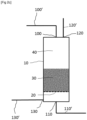
- FIG 2d presents a variant of the embodiment of the figure 1 , in every respect identical to this first mode (thus, the common elements will not be described again), with the exception of an external short circuit 140, in the form of a conduit external to the enclosure 10, making part of the means for evacuating the liquid effluent from the system according to the invention.
- the external short circuit 140 connects the upper part of the free volume 40 of the enclosure 10 to the lower part of the enclosure 10 located under the support 20 of the granular medium 30. This makes it possible to avoid a backflow of the liquid effluent through the two openings 100, 120 located in the upper part of the enclosure.
- a 2-way valve 53 is placed on the pipe 140 to prevent gas rising in the vertical upward direction during a regeneration phase of the granular medium.
- the two-way valve 53 can advantageously be replaced by a non-return valve (not shown).
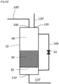
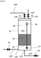
- FIG. 2e presents a variant of the embodiment of the figure 1 , in every respect identical to this first mode (thus, the common elements will not be described again), with the exception of an internal short circuit 140 in the enclosure, in the form of an internal conduit, forming part means for evacuating the liquid effluent from the system according to the invention.
- the internal short circuit 140 comprises a pipe directly connecting the upper part of the free volume 40 of the enclosure 10 to the lower part of the enclosure located under the support 20 of the granular medium 30. This makes it possible to avoid a discharge of the liquid effluent through the two openings 100, 120 located in the upper part of the enclosure.
- the internal circuit is surmounted by a deflector 56 to prevent the liquid effluent entering through the opening 100 from penetrating directly into the internal short circuit 140.
- the internal circuit 140 according to this variant is provided with a non-return valve 57 preventing the rise of gas in the pipe 140 in the vertical upward direction during a regeneration phase of the granular medium.
- FIG 2f presents a variant of the embodiment of the figure 1 , in every respect identical to this first mode (thus, the common elements will not be described again), with the exception of an additional chamber 11, arranged upstream of the enclosure 10, along the drain pipe 100' leading to the opening 100 of the means for the passage by percolation of the liquid effluent through the granular medium 30.
- This chamber 11 contributes to delaying the filtration, by reducing the speed of filtration of the liquid effluent through the granular medium 30, depending on the operating conditions or depending on the clogging. This makes it possible to avoid backflow of the liquid effluent by the two openings 100, 120 located in the upper part of the enclosure 10 if the flow rate in the filtration bed is lower than the drain flow rate.
- the flow between chamber 11 and enclosure 10 takes place mainly by gravity, chamber 11 being located substantially above enclosure 10.
- the system according to the invention further comprises means for controlling the means of passage by percolation of the liquid effluent through the granular medium and/or said means for evacuating the liquid effluent, and /or means of connection to said means of regeneration by fluidization of said granular medium.
- control means may include 2-way valves, 3-way valves, 6-way rotary valves, and/or check valves.
- control means make it possible to control the two phases of the process according to the invention: 1) during the filtration phase, only the liquid effluent can enter and leave the enclosure, and only via the means for passage by percolation liquid effluent through the granular medium and the means of evacuating the liquid effluent; 2) during the regeneration phase, only the gas from the regeneration means by fluidization of the granular medium can circulate in the enclosure. Combinations of these means of control are of course possible. Different configurations, non-limiting and non-exhaustive, are presented in the figures 3 to 7b .
- FIG 3 illustrates, in a schematic and non-limiting manner, an embodiment of the invention, comprising an external short circuit 140 (as described in figure 2d ) and means of connection to the means of regeneration by fluidization of said additional granular medium 130, 130' (such as described in section figure 2c ), and comprising 2-way valves 51, 52, 53, 54, 55 placed on each of the pipes 100', 110', 120', 130' connected respectively to the openings 100, 110, 120, 130 of the enclosure, and on the external short circuit 140.
- the valves 51, 52, 54, 55 make it possible to open or close the openings 100, 110, 120, 130 respectively during the filtration or regeneration phases.
- the gas is prevented from circulating in the external short circuit 140 thanks to the valve 53 installed on the short circuit.
- the two-way valve 53 can advantageously be replaced by a non-return valve (not shown).
- FIG 4 illustrates, in a schematic and non-limiting manner, an embodiment of the invention, comprising an internal short circuit 140 (as described in figure 2e ) and means of connection to the means of regeneration by fluidization of said additional granular medium 130, 130' (such as described in section figure 2c ), in which 2-way valves 51, 52, 54, 55 are placed on each of the pipes 100', 110', 120', 130' connected respectively to the openings 100, 110, 120, 130 of the enclosure, and a check valve 57 is arranged at the base of the internal short circuit pipe 140.
- the valves 51, 52, 54 55 make it possible to open or close the openings respectively 100, 110, 120, 130 during the filtration or regeneration phases.
- the non-return valve 57 makes it possible to avoid the rise of gas in the pipe 140 in the vertical upward direction during a regeneration phase of the granular medium 30.
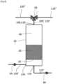
- FIG 5 illustrates, in a schematic and non-limiting manner, an embodiment of the invention, comprising means of connection to the means of regeneration by fluidization of said additional granular medium 130, 130' (as described in figure 2c ), and in which the openings 100, 120 of the means of passage by percolation of the liquid effluent through the granular medium 30 and the means of connection to the means of regeneration by fluidization of the granular medium are common, and in which a valve 3 channels 58 is arranged at the junction of the pipes 100', 120', 120" and 130" to control the fluid passing through these pipes 100', 120', 120", 130", depending on the current phase of the process according to the invention, that is to say to allow only the passage of the liquid effluent in the elements 100, 100' and 100" during the filtration phase, and only the passage of the gas in the elements 120, 120 ', 120" during the regeneration phase.
- non-return valves 59, 60 are also arranged on each of the pipes 110', 130' connected respectively to the openings 110, 130 of the lower part of the enclosure 10, so as not to allow the evacuation of the liquid effluent only through the opening 110, and the admission or insufflation of gas only through the opening 130.
- FIG. 6 illustrates, in a schematic and non-limiting manner, a variant of the figure 5 , in which the openings 110, 130 of the means for evacuating the liquid effluent and the means of connection to the means of regeneration by fluidization of the granular medium are also common, and in which a 3-way valve 61 is arranged at the junction of the pipes 110', 130', 110", 130" to control the fluid passing through these pipes 110', 130', 110", 130", depending on the current phase of the process according to the invention.
- the use of the 3-way valves 58, 61 makes it possible to use the system according to the invention in the filtration phase or in the regeneration phase.
- the valve 58 opens the opening 100 and closes the opening 120, and the valve 61 opens the opening 110 and closes the opening 130.
- the valve 58 opens the opening 120 and closes the opening 100, and the valve 61 opens the opening 130 and closes the opening 110.
- the passage of the liquid effluent is only possible during the filtration phase, and only in the elements 100, 100', 100", 110, 110'110", and the passage of gas is only possible during the regeneration phase, and only in elements 120, 120', 120", 130, 130", 130" .
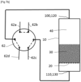
- THE figures 7a And 7b illustrate, in a schematic and non-limiting manner, a mode of implementation of the invention, in which the means for controlling the means of passage by percolation of the liquid effluent through the granular medium, the means for evacuating the liquid effluent, and the means of connection to the means of regeneration by fluidization are controlled by a rotary 6-way valve 62.
- the openings 100, 120 of the means of passage by percolation of the liquid effluent through of the granular medium and the means of connection to the means of regeneration by fluidization of the granular medium are common, as are the openings 110, 130 of the means for evacuating the liquid effluent and the means of connection to the means of regeneration by fluidization of the medium granular.
- FIG 7a illustrates schematically, by dotted lines, the positions of the elements 62a, 62b, 62c, and 62d of the 6-way valve 62, to connect, during the filtration phase, only the opening 100 to the opening 110 .
- FIG 7b illustrates schematically, by dotted lines, the positions of the elements 62a, 62b, 62c, and 62d of the 6-way valve 62 to connect, during the regeneration phase, only the opening 130 to the opening 120.
- the system according to the invention may further comprise a settling chamber and/or a cyclonic separation chamber (such as a hydrocyclone), arranged upstream of the enclosure, and connected to the enclosure by the means for the passage by percolation of the liquid effluent through the granular medium.
- a settling chamber allows the sedimentation of the largest fibers by gravity.
- a cyclonic separation chamber (such as a hydrocyclone) makes it possible to separate larger fibers by inducing vorticity and a centrifugal force field favoring separation.
- Such chambers positioned upstream of the enclosure in relation to the flow of liquid effluent, can make it possible to capture the largest fibers and limit too rapid clogging of the granular medium, which will then be able to capture the majority of the largest fibers more effectively. small fibers.
- the system according to the invention further comprises means for injecting at least one flocculating agent into the liquid effluent, arranged for an injection of the flocculating agent into the liquid effluent before its arrival in the granular medium .
- These means for injecting at least one flocculating agent into the liquid effluent can either be arranged upstream of the enclosure and connected to the enclosure by means for the passage by percolation of the liquid effluent through the medium granular, or arranged so as to allow injection into the free volume above the granular medium, via an opening made in the upper part of the enclosure.
- the means for injecting at least one flocculating agent may comprise a reservoir comprising said at least one flocculating agent as well as means allowing to control the flow of the flocculating agent. It is also possible, for example in the case where the flocculating agent is in liquid or solid form, to mix the flocculating agent with the liquid in the device allowing the textile to be treated, for example mixed with the detergent in the case of a washing machine.
- a flocculating agent helps promote the agglomeration of the smallest fibers, which facilitates their separation from the liquid effluent as it passes through the granular medium.
- a flocculating agent in the form of mineral salts with multivalent cations such as alumina sulfate or ferric chloride, activated silica, or natural organic polyelectrolytes (starches, alginate) or synthetic polyelectrolytes (molecular mass polymers). high such as polycrylamides or polyvinylamines).
- the injection of a flocculating agent is preferably carried out at a low content, generally between 1 and 20 ppm of the drain liquid, and a device favoring the mixing of said flocculating agent in the liquid effluent is preferably used.
- Flocculation is particularly interesting in the case where the microfibers have dimensions of the order of one micron or less than one micron.
- FIG 8 illustrates an embodiment of the system according to the invention, comprising a granular medium formed by three layered particle beds 30a, 30b, 30c, arranged on three supports 20a, 20b, and 20c, each bed 30a, 30b, 30c being surmounted by a free volume 40a, 40b, 40c.
- the opening 120 provided in the upper wall of the enclosure 10 is intended to be connected to means of regeneration by fluidization of the granular medium (not shown).
- the invention further relates to a method for the filtration of microfibers contained in a liquid effluent, which can advantageously be implemented by means of the system for the filtration of microfibers contained in a liquid effluent according to any one of the embodiments or any combination of the embodiments described above.
- step A) is repeated between 20 and 150 times, preferably around 100 times before carrying out step B).
- it is important to regularly regenerate the filtering medium in order to avoid clogging, but it may not be necessary to carry out a regeneration phase systematically after each filtration phase, depending on the microfiber load.
- liquid effluent we can estimate a frequency of triggering the regeneration phase, by estimating a speed of clogging of the porosity of the filter bed by accumulation of microfibers, from the concentration of microfibers in the liquid effluent at each wash. This embodiment, by avoiding systematic regeneration phases, notably allows energy savings.
- a regeneration phase is carried out by fluidization of the granular medium, after a plurality of filtration phases, when it is detected that the percolation rate of the liquid effluent slows down.
- a regeneration phase of the granular medium can be triggered in the following manner: for each filtration phase, the variation in the level of the liquid effluent in the free volume above the granular medium is measured as a function.
- this measurement is compared to a reference value of the percolation flow rate, obtained for example by measurement when the granular medium is free of microfibers; when the measurement is at least 100% lower than the reference value, or preferably at least 50% lower than the reference value, a regeneration phase is carried out by fluidization of the granular medium at the end of the current filtration phase .
- the regeneration phase can only be triggered by fluidization of the granular medium after a predetermined duration, taken from the end of the last filtration phase, allowing at least the drainage of the liquid effluent and preferably also the drainage. drying of the granular medium, in order to evacuate all the humidity contained in the granular medium.
- This predetermined duration can be between 3 and 7 hours, preferably 5 hours.
- to promote drying it is also possible to establish a natural or forced convection of gas through the granular medium, by keeping open the openings of the means for evacuating the liquid effluent and the means of connection to the means of regeneration by fluidization of the granular medium.
- the predetermined duration will advantageously be limited when hydrophobic particles are used and/or the filter is constructed with a hydrophobic material.
- the method according to the invention may comprise, prior to step b), a phase of drainage of the granular medium, carried out by means of gaseous suction means connected to the system according to the invention so as to generate a descending flow of gas through the granular medium.
- the means of suction gas are connected to the system according to the invention at an opening located under the granular medium, and preferably above the lower wall of the enclosure.
- the gas suction means can be connected to the opening of the means for evacuating the liquid effluent, or alternatively, when it exists, to the additional opening of the means connection to the means of regeneration by fluidization of the granular medium described above.
- the opening to which the gas suction means are connected is located at a side higher than the side of the lower wall of the enclosure, and comprises a deflector to prevent the drained liquid effluent from entering the means of suction. gaseous aspiration.
- the system according to the invention may comprise means for collecting (such as water traps) the drained liquid effluent, located upstream of the opening connected to the gas suction means, to avoid excessive entrainment of liquid. towards the gaseous suction means, these liquid entrainments being able to be detrimental to the proper functioning of these gaseous suction means.
- the method according to the invention can comprise, prior to step b) and preferably after a drainage phase as described above, a drying phase of the granular medium, carried out by means of means for increasing the temperature of the granular medium.
- This drying phase allows accelerated drying compared to a drainage phase as described above which would be carried out over a sufficiently long time to result in the drying of the granular medium.
- this drying phase of the granular medium can be carried out by connecting gas blowing means to the system according to the invention so as to generate an ascending or descending flow of gas through the granular medium. , and by previously heating the gas before entering the enclosure.
- the gas can for example be heated by means of a heat source (for example a heating resistor, a heat exchanger) located between the gas blowing means and the opening to which the gas blowing means are connected.
- a heat source for example a heating resistor, a heat exchanger
- the gas insufflation means can be connected to the system according to the invention at level of the opening of the means for regeneration by fluidization of the granular medium located above the granular medium, or at the level of the additional opening arranged under the support of the granular medium as described above, or any other opening .
- the gas used is a gas with little water vapor content.
- the gas insufflation means may consist of a hair dryer.
- this phase of drying the granular medium can be carried out by increasing the temperature of the granular medium by percolating a hot liquid through the granular medium, or by heating the walls of the granular medium. Heating the wall of the granular medium can be carried out for example by placing a heating resistance in contact with the wall of the granular medium, or in the wall of the granular medium itself.
- the granular medium is heated to temperatures between 30 and 90°C, preferably between at least 50 and 70°C. Such temperatures are capable of allowing the evacuation of more than 95% of the residual humidity, present in the granular medium at the start of drying, in a period of less than 30 minutes, or even less than 10 minutes.
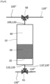
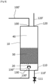
- FIG. 9 presents a variant of the embodiment of the figure 1 (thus, the common elements will not be described again), configured to implement a phase of drainage of the granular medium followed by a phase of drying of the granular medium, before regenerating it.
- an additional opening 130 is provided in the enclosure at a side higher than the side of the lower wall of the enclosure, this opening 130 being intended to be connected to gas suction means (not shown) by driving 130'.
- this opening 130 is surmounted by a deflector 130" making it possible to deflect the gravity flow of liquid, through the granular medium 30, around the opening 130, while allowing the gas to pass which undergoes an infinitely weaker manner. the effects of gravity.
- the pipe 110' making it possible to connect the opening 110 to a waste water evacuation system (not shown), is provided with a valve 111 allowing the evacuation (open valve) of the liquid effluent accumulated before and during the drainage phase.
- the system is connected to the gas suction means through the opening 130 and the pipe 130', the air being sucked from the ambient medium through the opening 120.
- a gas current passes through the bed at a speed preferably between 0.1 and 5 m/s, preferably around 0.3 to 3 m/s.
- the gas promotes the flow of the liquid accumulated in the granular medium during the successive filtration phases.
- the residual liquid therefore flows through the granular medium 30 and the support 20 and accumulates around the conduit 130' under the opening 130 in the space located in the system 10 under the support 20.
- the gas suction is stopped.
- the liquid accumulated around conduit 130' is evacuated via pipeline 110 by opening valve 111.
- the granular medium having undergone drainage is then dried before being regenerated. It is possible, in this configuration, to keep the gas suction means connected to the opening 130 and to connect a hair dryer (not shown) to the opening 120 via the conduit 120'. Ambient air heated to approximately 50°C then enters the system through opening 120, passes through the filtering medium, giving it its heat, and gradually taking on the humidity resulting from the evaporation of water. dictated by the local conditions of thermodynamic equilibrium.
- the granular medium is regenerated, in the absence of excessive humidity which could harm the fluidization of the particles.
- the gas suction means are then connected to the opening 120, the gas fluidizing the granular medium entering through the opening 110.
- the filtration and/or regeneration phases are controlled by means of the system control means for the filtration of microfibers described above, for example by means of 2-way valves, 3-way valves, 6-way rotary valves, and/or check valves, as described above, and in particular in the embodiments of the figures 3 to 7b .
- the process according to the invention comprises at least one preliminary step (that is to say before step A) of pretreatment of the liquid effluent, before its arrival on the granular medium.
- this preliminary step of pretreatment of the liquid effluent may comprise a sub-step of injecting at least one flocculating agent into the liquid effluent, for example by means of the means of injection of a flocculating agent as described above.
- a flocculating agent helps promote the agglomeration of the smallest fibers, which facilitates their separation from the liquid effluent as it passes through the granular medium.
- a flocculating agent in the form of mineral salts with multivalent cations such as alumina sulfate or ferric chloride, activated silica, or natural organic polyelectrolytes (starches, alginate) or synthetic polyelectrolytes (molecular mass polymers). high such as polycrylamides or polyvinylamines).
- the injection of a flocculating agent will preferably be carried out at a low content, generally between 1 and 20 ppm of the drain liquid, and a device will preferably be used to promote the mixing of said flocculating agent in the liquid effluent. Flocculation is particularly interesting in the case where the microfibers have dimensions of the order of one micron or less than one micron.
- the flocculating agent can also be injected at the same time time as the detergent intended for washing textiles, and possibly be combined with the detergent.
- the preliminary step of pretreatment of the liquid effluent may comprise a sub-step of decantation of the liquid effluent, carried out for example by means of a decantation chamber arranged upstream of the enclosure of the system according to the invention as described above.
- a settling chamber allows the sedimentation of the largest fibers by gravity.
- the preliminary step of pretreatment of the liquid effluent may comprise a sub-step of passing the liquid effluent into a cyclonic separation chamber (such as a hydrocyclone) placed upstream of the system enclosure.
- a cyclonic separation chamber such as a hydrocyclone
- a cyclonic separation chamber makes it possible to separate larger fibers by inducing vorticity and a centrifugal force field favoring separation.
- Such a preliminary sub-step can make it possible to capture the largest fibers and limit too rapid clogging of the granular medium, which will then be able to more effectively capture the majority of the smallest fibers.
- the preliminary step of pretreatment of the liquid effluent may comprise a sub-step of injecting at least one flocculating agent into the liquid effluent, followed by a sub-step of settling the effluent liquid and/or a cyclonic separation sub-step.
- the flocculating agent makes it possible to promote the agglomeration of the smallest fibers, which will increase the efficiency of the decantation and/or cyclonic separation sub-step, before the passage of the liquid effluent, already discharged from the largest large fibers and/or agglomerates of fibers, in the granular medium.
- the method according to the invention further comprises at least one step subsequent to the regeneration step, consisting of the collection of microfibers resulting from the regeneration phase, for example by means of a cyclonic chamber or a filter (for example membrane) placed downstream of the means for regenerating by fluidization of said granular medium described above.
- the system and the method according to the invention make it possible to filter the microfibers from a liquid effluent, resulting from the washing, rinsing and/or spinning phases of a textile treatment device, with capture efficiency microfibers greater than 50 microns greater than at least 80%.
- the system and the method according to the invention do not require consumables, and can be used over a long period of time, thanks to the possibility of regenerating the granular environment in which microfibers can accumulate over time.
- the invention also relates to a device for washing textiles, such as a washing machine, comprising at least one system for the filtration of microfibers contained in a liquid effluent according to any one of the embodiments described above.
- the invention is not limited only to the embodiments of the system and the method, described and illustrated above by way of example, on the contrary it embraces all the variant embodiments, as well as all the combinations, of these embodiments, so as to combine their effects.
- the embodiments of figures 2a to 2f can be combined with each other.
- These embodiments can also be combined with the embodiments of the figures 3 to 6 , and/or figures 7a to 7b and/or the figure 8 .
- These embodiments can also be combined with the embodiment of the Figure 9 .
- the washing machine in this example has a washing capacity of 5kg of laundry, and uses a maximum total quantity of water of 501 for each wash.
- the washing water evacuation cycles during the different phases of the program are variable depending on the user's choices but the washing machine is characterized by the fact that the largest quantity that it is possible to evacuate during a phase during washing is 15l, the evacuation of the liquid being carried out in 3 minutes. Between two washing machine evacuation cycles, the time is approximately 15 minutes minimum.
- the average fiber content in the waste water is close to 0.02 g/l, corresponding to an average fiber release rate of 0.02% relative to the weight of washed laundry, and to an average quantity of fibers to be collected by the filter with each wash of 1g on average for 5 kg of washed laundry.
- the washing machine discharges drain fluids through a drain point located at the base of the washing machine 5 cm from the floor.
- a connection point to the sewer is available at a height located 15 cm above the drain point of the washing machine (therefore 40 cm from the floor on which the washing machine rests).
- the filtration system according to the design described in the figure 5 is incorporated directly into the washing machine.
- the references cited below therefore correspond to those of the figure 5 .
- the enclosure 10 containing the granular medium 30 is cylindrical, with an internal diameter of 25 cm and 60 cm high.
- the granular medium 30 is placed over a height of 25 cm in the enclosure 10. It is surmounted by a free volume 40 with a height of 30 cm, the volume of which allows the accumulation of 15 I of liquid effluent.
- the granular medium rests on a support 20 in the form of a grid whose mesh size is 0.15 mm. Under the grid, an empty space of 50 mm allows the liquid to be collected under the filter bed.
- the granular medium 30 consists of sand whose average diameter is 0.5 mm, and such that 90% of the sand particles have a size between 0.3 and 0.7mm.
- the average density of sand grains is estimated at 2550 kg/m3.
- the porosity (interstitial space) of the granular medium 30 is estimated at 41% of the granular volume after regeneration.
- a short circuit of 10 mm internal diameter and 12 mm external diameter fitted with a non-return valve passes through the bed (as shown in the figure 4 ).
- the filtration system according to this example of application is connected to the washing machine using a 100' flexible hose which connects the washing machine drain line 100" to the 3-way valve 58 located at a high point at 105 cm above the washing machine drain outlet, i.e. 110 cm from the floor.
- the opening 110 is therefore still located above the washing machine drain outlet, which makes it possible to connect the opening 110 to the usual wastewater evacuation system, with a siphon and to evacuate the filtered rinsing liquid by gravity.
- the 3-way valve 58 is in the position allowing the drain liquid to be filtered, or in other words, the opening 100 is open and the opening 120 is closed.
- the characteristics of the bed allow filtration with a flow rate of 6l/min by creating a pressure loss less than 2000 Pa, corresponding to a hydrostatic height of 20 cm less than the height of the free volume 40.
- filtration by percolation of the bed can be carried out in less than 4 minutes.
- the pressure loss has doubled and corresponds to approximately 4000 Pa, i.e. a hydrostatic height of 40 cm always lower than the height of the free volume 30.
- the three-way valve 58 is activated to regenerate the filtering medium.
- the opening 100 is closed and the opening 120 is open.
- a commercial vacuum cleaner equipped with a disposable filter bag is connected to the opening 120, making it possible to create a convective current of ascending air through the granular medium 30 , the air entering through the opening 130 provided with the non-return valve 59 which opens, the opening 110 being automatically closed thanks to the non-return valve 60.
- the vacuum cleaner allows you to suck up 30l/s with a suction of 40 kPa.
- the fluidization speed of the particles is 19.5 cm/s.
- a minimum flow rate of 10 I/s is therefore required to fluidize the bed.
- Using the vacuum cleaner which sucks up 30 l/s therefore makes it possible to fluidize the bed at a speed corresponding to 3 times the minimum fluidization speed.
- the suction necessary to compensate for the pressure loss of the granular medium in the fluidized state is approximately 4000 Pa which is much lower than the suction capacity of the vacuum cleaner.
- the bed is therefore well fluidized, which allows the microfibers to be evacuated towards the filter bag.
- the three-way valve 58 is actuated to return to the filtration phase, that is to say that the opening 100 is open and the opening 120 is closed.
- the system and process for the filtration of microfibers according to this design made it possible to eliminate between 80 and 90% of fibers longer than approximately 50 microns.
- the dimensions of the filtration system described in the application example could be reduced by optimizing the operating conditions of the washing machine, for example by considering more frequent drains but of a smaller volume.
Landscapes
- Chemical & Material Sciences (AREA)
- Chemical Kinetics & Catalysis (AREA)
- Engineering & Computer Science (AREA)
- Textile Engineering (AREA)
- Filtering Materials (AREA)
- Soy Sauces And Products Related Thereto (AREA)
Claims (20)
- System zur Filterung von Mikrofasern, die in einer Ablaufflüssigkeit aus einer Textilbehandlungsvorrichtung enthalten sind, wobei das System dazu bestimmt ist, mit einer Leitung für die Entleerung der Textilbehandlungsvorrichtung verbunden zu sein, dadurch gekennzeichnet, dass das System wenigstens Folgendes umfasst:- eine Einhausung (10), die ein körniges Medium (30) umfasst, das einen Teil des Raums der Einhausung (10) einnimmt, wobei das körnige Medium (30) so auf einem Träger (20) angeordnet ist, dass ein freies Volumen (40) in der Einhausung (10) über dem körnigen Medium (30) belassen ist, wobei der Träger (20) wenigstens für die Ablaufflüssigkeit durchlässig ist;- Mittel (100) für den Durchtritt durch Perkolation der Ablaufflüssigkeit durch das körnige Medium (30), die wenigstens eine Öffnung (100) umfassen, die in der Einhausung (10) eingerichtet und über dem körnigen Medium (30) angeordnet ist;- Ableitungsmittel (110) für die Ablaufflüssigkeit, die wenigstens eine Öffnung (110) umfassen, die in der Einhausung (10) eingerichtet und unter dem Träger (20) des körnigen Mediums (30) angeordnet ist;- Mittel zum Anschluss (120, 130) an Mittel zur Regeneration durch Fluidisierung des körnigen Mediums (30), dadurch gekennzeichnet, dass die Anschlussmittel wenigstens eine Öffnung (120) umfassen, die in der Einhausung (10) eingerichtet und über dem körnigen Medium (30) angeordnet ist.
- System nach Anspruch 1, wobei die Mittel zum Anschluss (120, 130) an die Mittel zur Regeneration durch Fluidisierung des körnigen Mediums (30) eine Zusatzöffnung (130) umfassen, die in der Einhausung (10) eingerichtet und unter dem Träger (20) des körnigen Mediums (30) angeordnet ist, wobei die Zusatzöffnung (130) der Anschlussmittel geeignet ist, an Mittel für einen Einlass eines Gases und/oder für ein Einblasen eines Gases angeschlossen zu sein.
- System nach einem der vorhergehenden Ansprüche, wobei die Ableitungsmittel (110) für die Ablaufflüssigkeit einen Kreis (140) außerhalb der Einhausung (10) umfassen, der mit der Einhausung (10) verbunden ist, um das körnige Medium (30) im Falle einer Ansammlung der Ablaufflüssigkeit im freien Volumen (40) der Einhausung (10) über dem körnigen Medium (30) zu umgehen.
- System nach einem der vorhergehenden Ansprüche 1 bis 2, wobei die Ableitungsmittel (110) für die Ablaufflüssigkeit eine Leitung (140) umfassen, die wenigstens das körnige Medium (30) durchquert, um das körnige Medium (30) im Falle einer Ansammlung der Ablaufflüssigkeit im freien Volumen (40) der Einhausung (10) über dem körnigen Medium (30) zu umgehen, wobei die Leitung (140) vorzugsweise in ihrem oberen Abschnitt mit einem Abweiser (56) versehen ist.
- System nach Anspruch 3, wobei der Kreis (140) außerhalb der Einhausung ferner einen Flüssigkeitsdetektor aufweist, der vorzugsweise mit einer Alarmeinrichtung verbunden ist.
- System nach Anspruch 4, wobei die Leitung (140) der Ableitungsmittel (110) der Ablaufflüssigkeit ferner einen Flüssigkeitsdetektor aufweist, der vorzugsweise mit einer Alarmeinrichtung verbunden ist.
- System nach einem der vorhergehenden Ansprüche, ferner umfassend Mittel zur Steuerung (51, 52, 53, 54, 55, 57, 58, 59, 60, 61, 62) der Mittel zum Durchtritt durch Perkolation (100) der Ablaufflüssigkeit durch das körnige Medium (30) und/oder der Ableitungsmittel (110) der Ablaufflüssigkeit und/oder der Mittel zum Anschluss (120, 130) an die Mittel zur Regeneration durch Fluidisierung des körnigen Mediums (30).
- System nach Anspruch 7, wobei die Steuermittel wenigstens ein 2-Wege-Ventil (51, 52, 53, 54, 55) und/oder wenigstens ein 3-Wege-Ventil (58, 61) und/oder wenigstens eine Rückströmsperre (57, 59, 60) und/oder ein drehbares 6-Wege-Ventil (62) umfassen können.
- System nach einem der vorhergehenden Ansprüche, das ferner eine Klärkammer und/oder eine Zyklonabscheidekammer und/oder eine Sammelkammer (11) der Ablaufflüssigkeit umfasst, die stromauf der Einhausung (10) angeordnet sind und an die Mittel (100) für den Durchtritt durch Perkolation der Ablaufflüssigkeit durch das körnige Medium (30) angeschlossen sind.
- System nach einem der vorhergehenden Ansprüche, das ferner Mittel zur Einspritzung wenigstens eines Flockungsmittel in die Ablaufflüssigkeit umfasst, wobei die Einspritzmittel für eine Einspritzung des wenigstens einen Flockungsmittels in die Ablaufflüssigkeit stromauf des körnigen Mediums (30) angeordnet sind.
- System nach einem der vorhergehenden Ansprüche, wobei das körnige Medium (30) Sandpartikel, Kugeln aus zerkleinertem Glas oder rohe Glaskugeln, Partikel, die auf Basis von natürlichem oder synthetischem Zeolith, auf Basis von Tonerde oder auch auf Harz- oder Kunststoffbasis gebildet sind, umfasst.
- System nach einem der vorhergehenden Ansprüche, wobei das körnige Medium (30) Partikel mit einer Größe zwischen 0,1 mm und 2 cm für wenigstens 80 Gewichts-% der Partikel, vorzugsweise zwischen 0,3 und 2,5 mm für wenigstens 90 Gewichts-% der Partikel umfasst.
- System nach einem der vorhergehenden Ansprüche, wobei ein Flüssigkeitsverteiler zwischen dem körnigen Medium (30) und der Öffnung (100) der Mittel (100) für den Durchtritt durch Perkolation der Ablaufflüssigkeit durch das körnige Medium (30) angeordnet ist, und/oder, wenn die Mittel zur Regeneration durch Fluidisierung des körnigen Mediums (30) Gasansaugmittel umfassen, ein Gasverteiler zwischen dem körnigen Medium (30) und einer Öffnung, die zum Einlass des Gases der Gasansaugmittel bestimmt ist, angeordnet ist.
- Verfahren zur Filterung von Mikrofasern, die in einer Ablaufflüssigkeit aus einer Textilbehandlungsvorrichtung enthalten sind, wobei das Verfahren mittels eines Systems zur Filterung von Mikrofasern nach einem der vorhergehenden Ansprüche durchgeführt wird, dadurch gekennzeichnet, dass das Verfahren wenigstens die folgenden Schritte umfasst:A) Es wird wenigstens eine Phase des Filtrierens der Mikrofasern durchgeführt, wobei die Phase des Filtrierens wenigstens einen Durchtritt durch Perkolation der Ablaufflüssigkeit durch das körnige Medium (30) mittels wenigstens der Mittel (100) für den Durchtritt durch Perkolation der Ablaufflüssigkeit durch das körnige Medium (30) und das Ableiten der filtrierten Ablaufflüssigkeit mittels wenigstens der Ableitungsmittel (110) für die Ablaufflüssigkeit umfasst;B) Es wird eine Phase des Regenerierens durch Fluidisierung des körnigen Mediums (30) durch Verbindung der Mittel zum Anschluss (120, 130) an die Mittel zur Regeneration durch Fluidisierung des körnigen Mediums (30) mit den Mitteln zur Regeneration durch Fluidisierung des körnigen Mediums (30) durchgeführt.
- Verfahren nach Anspruch 14, wobei Schritt A) zwischen 50 und 150 mal, vorzugsweise ungefähr 100 mal wiederholt wird, bevor der Schritt B) durchgeführt wird.
- Verfahren nach einem der Ansprüche 14 bis 15, umfassend vor dem Schritt A) einen Schritt des Vorbehandelns der Ablaufflüssigkeit, wobei der Schritt des Vorbehandelns der Ablaufflüssigkeit wenigstens eine Einspritzung wenigstens eines Flockungsmittels in die Ablaufflüssigkeit und/oder wenigstens ein Klären der Ablaufflüssigkeit und/oder wenigstens eine Zyklonabscheidung der Ablaufflüssigkeit umfasst.
- Verfahren nach einem der Ansprüche 14 bis 16, umfassend, vor dem Schritt B), eine Phase des Drainierens des körnigen Mediums, die mittels Gasansaugmitteln durchgeführt wird, die mit dem System verbunden sind, so dass sie einen Abwärtsgasstrom durch das körnige Medium erzeugen, und/oder eine Phase des Trocknens des körnigen Mediums, die mithilfe von Mitteln zur Erhöhung der Temperatur des körnigen Mediums durchgeführt wird.
- Verfahren nach einem der Ansprüche 14 bis 17, wobei die Phasen des Filtrierens und des Regenerierens mithilfe der Mittel zur Steuerung (51, 52, 53, 54, 55, 57, 58, 59, 60, 61, 62) des Systems zur Filterung von Mikrofasern nach einem der Ansprüche 5 bis 6 gesteuert werden.
- Verfahren nach einem der Ansprüche 14 bis 18, ferner umfassend wenigstens einen Schritt nach der Phase des Regenerierens durch Fluidisierung, der im Sammeln der Mikrofasern aus der Phase des Regenerierens, vorzugsweise mittels einer Zyklonkammer und/oder eines Membranfilters, die stromab der Mittel zur Regeneration durch Fluidisierung des körnigen Mediums (30) angeordnet sind, besteht.
- Textilwaschvorrichtung umfassend wenigstens ein System zur Filterung von Mikrofasern, die in einer Ablaufflüssigkeit enthalten sind, nach einem der Ansprüche 1 bis 13.
Applications Claiming Priority (3)
| Application Number | Priority Date | Filing Date | Title |
|---|---|---|---|
| FR2003351A FR3108921B1 (fr) | 2020-04-03 | 2020-04-03 | Systeme et procede regenerable de filtration de microfibres d'un liquide de vidange |
| FR2101003A FR3108922B1 (fr) | 2020-04-03 | 2021-02-02 | Systeme et procede regenerable de filtration de microfibres d'un liquide de vidange |
| PCT/EP2021/057473 WO2021197937A1 (fr) | 2020-04-03 | 2021-03-23 | Systeme et procede regenerable de filtration de microfibres d'un liquide de vidange |
Publications (3)
| Publication Number | Publication Date |
|---|---|
| EP4127301A1 EP4127301A1 (de) | 2023-02-08 |
| EP4127301B1 true EP4127301B1 (de) | 2024-03-20 |
| EP4127301C0 EP4127301C0 (de) | 2024-03-20 |
Family
ID=70804819
Family Applications (1)
| Application Number | Title | Priority Date | Filing Date |
|---|---|---|---|
| EP21713411.3A Active EP4127301B1 (de) | 2020-04-03 | 2021-03-23 | Regenerierbares system und verfahren zum filtern von mikrofasern aus einer abfallflüssigkeit |
Country Status (8)
| Country | Link |
|---|---|
| US (1) | US20230149835A1 (de) |
| EP (1) | EP4127301B1 (de) |
| CN (1) | CN115298383A (de) |
| CA (1) | CA3172198A1 (de) |
| ES (1) | ES2981407T3 (de) |
| FR (2) | FR3108921B1 (de) |
| PL (1) | PL4127301T3 (de) |
| WO (1) | WO2021197937A1 (de) |
Families Citing this family (5)
| Publication number | Priority date | Publication date | Assignee | Title |
|---|---|---|---|---|
| ES2942810B2 (es) * | 2021-12-03 | 2024-02-08 | Desinope 323 S L | Instalacion y procedimiento de captacion de microplasticos y microfibras |
| FR3130298A1 (fr) | 2021-12-09 | 2023-06-16 | IFP Energies Nouvelles | Systeme et procede regenerable de filtration de microfibres d'un liquide de vidange |
| BE1030879B1 (de) * | 2022-09-15 | 2024-04-15 | Miele & Cie | Filtervorrichtung für eine Waschmaschine, Waschmaschine und Verfahren zum Betrieb einer Waschmaschine |
| US12427453B2 (en) * | 2022-11-25 | 2025-09-30 | Samsung Electronics Co., Ltd. | Microplastic filter for washing machines or other appliances |
| FR3156776A1 (fr) | 2023-12-15 | 2025-06-20 | IFP Energies Nouvelles | Systeme et procede de recuperation de microfibres textiles d'un liquide de vidange par flottation a air dissous |
Family Cites Families (13)
| Publication number | Priority date | Publication date | Assignee | Title |
|---|---|---|---|---|
| US4906367A (en) | 1989-03-27 | 1990-03-06 | Villagomez Timothy A | Lint strainer for washing machine drains |
| FR2742352B1 (fr) * | 1995-12-18 | 1998-02-27 | Ixtlan Ag | Procede et appareil pour filtrer des substances liquides ou pateuses et/ou pour separer des composants inclus dans ces substances |
| JP2001047075A (ja) * | 1999-08-10 | 2001-02-20 | Hitachi Ltd | 排水浄化装置およびこれを用いた洗濯機 |
| GB0517515D0 (en) * | 2005-08-26 | 2005-10-05 | Quill Internat Ind Plc | Improvements to washing machines |
| US20130220913A1 (en) * | 2012-02-23 | 2013-08-29 | Ticona Llc | Fluid filters with mechanically compacted filter beds comprising granular filter media and apparatuses and methods relating thereto |
| CN104514122B (zh) * | 2013-09-27 | 2017-01-18 | 海尔集团技术研发中心 | 一种絮凝洗衣机 |
| EP3180103A1 (de) * | 2014-08-15 | 2017-06-21 | Halosource, Inc. | Körnige filtermedienmischung und verwendungen in der wasseraufbereitung |
| CN105506934B (zh) * | 2014-09-22 | 2019-08-09 | 青岛海尔智能技术研发有限公司 | 洗衣机的过滤组件的自清洁方法 |
| DK2816150T3 (en) * | 2014-09-24 | 2018-05-22 | V Zug Ag | Aquatic household appliance with lye filter |
| DE102016100493A1 (de) | 2016-01-13 | 2017-07-13 | Oliver Spies | Rückhaltemittel für Kunststofffasern |
| CN109219680A (zh) | 2016-03-31 | 2019-01-15 | 罗萨利亚项目股份有限公司 | 纤维捕集器和移除纤维的方法 |
| FR3051680B1 (fr) * | 2016-05-30 | 2020-03-06 | IFP Energies Nouvelles | Nouveau systeme de distribution ou de collecte peripherique pour un procede de separation en lit mobile simule utilisant n-colonnes en serie |
| WO2019017848A1 (en) | 2017-07-20 | 2019-01-24 | Planet Care | METHOD AND DEVICE FOR REMOVING PARTICLES, PREFERABLY MICROFIBERS, WASTEWATER |
-
2020
- 2020-04-03 FR FR2003351A patent/FR3108921B1/fr active Active
-
2021
- 2021-02-02 FR FR2101003A patent/FR3108922B1/fr active Active
- 2021-03-23 WO PCT/EP2021/057473 patent/WO2021197937A1/fr not_active Ceased
- 2021-03-23 CA CA3172198A patent/CA3172198A1/fr active Pending
- 2021-03-23 CN CN202180023137.7A patent/CN115298383A/zh active Pending
- 2021-03-23 ES ES21713411T patent/ES2981407T3/es active Active
- 2021-03-23 EP EP21713411.3A patent/EP4127301B1/de active Active
- 2021-03-23 PL PL21713411.3T patent/PL4127301T3/pl unknown
- 2021-03-23 US US17/916,178 patent/US20230149835A1/en active Pending
Also Published As
| Publication number | Publication date |
|---|---|
| FR3108921A1 (fr) | 2021-10-08 |
| CN115298383A (zh) | 2022-11-04 |
| CA3172198A1 (fr) | 2021-10-07 |
| ES2981407T3 (es) | 2024-10-08 |
| PL4127301T3 (pl) | 2024-07-15 |
| US20230149835A1 (en) | 2023-05-18 |
| EP4127301C0 (de) | 2024-03-20 |
| WO2021197937A1 (fr) | 2021-10-07 |
| EP4127301A1 (de) | 2023-02-08 |
| FR3108922A1 (fr) | 2021-10-08 |
| FR3108922B1 (fr) | 2022-05-06 |
| FR3108921B1 (fr) | 2022-03-04 |
Similar Documents
| Publication | Publication Date | Title |
|---|---|---|
| EP4127301B1 (de) | Regenerierbares system und verfahren zum filtern von mikrofasern aus einer abfallflüssigkeit | |
| KR100738714B1 (ko) | 건조 겸용 세탁기 | |
| CN111032949A (zh) | 用于洗衣机的方法及洗衣机 | |
| CN117136095A (zh) | 用于过滤微粒的过滤单元和用于过滤单元的过滤笼 | |
| CN102666966A (zh) | 具有冷凝物收集器的衣物烘干机 | |
| JP2012519592A (ja) | 液体から粒子を分離する方法および装置 | |
| EP2664584B1 (de) | Filtervorrichtung für häusliches Grauwasser | |
| FR2678960A1 (fr) | Procede et dispositif d'elimination des depots de bourre dans le circuit de production d'air chaud des machines a laver et a secher le linge. | |
| EP0443961A1 (de) | Vorrichtung zur Vorbehandlung von Kunststoffabfällen vor ihrer Wiederaufbereitung | |
| US7882716B2 (en) | Dry-cleaning machine | |
| EP2341183A1 (de) | Betriebsverfahren eines Wäschetrockners und dieses Verfahren anwendender Wäschetrockner | |
| FR2931489A1 (fr) | Procede de retrait des peluches dans une machine a secher le linge comprenant un filtre a peluches | |
| WO2022184420A1 (fr) | Systeme et procede regenerable de filtration de microfibres d'un liquide de vidange | |
| EP3067107A1 (de) | Verbesserter filtereinsatz und filter zur filtration von fluiden | |
| EP1632598B1 (de) | Verfahren zur Wiederverwendung einer Wasch- oder Spülflüssigkeit in einer Wasch- oder Geschirrspülmaschine, Wasch- oder Geschirrspülmaschine und dazugehöriges Filtrationssystem | |
| FR2487690A1 (fr) | Procede et dispositif pour la separation huile-eau par coalescence | |
| CN118891409A (zh) | 过滤器布置 | |
| FR2477757A1 (fr) | Procede et machine pour decontaminer des vetements radioactifs | |
| FR3135402A1 (fr) | Dispositif de filtration | |
| WO2025124963A1 (fr) | Systeme et procede de recuperation de microfibres textiles d'un liquide de vidange par flottation a air dissous | |
| FR2931488A1 (fr) | Machine a secher le linge comprenant un filtre a peluches | |
| FR2724849A1 (fr) | Procede et dispositif d'elimination de composes par filtration sur membrane et charbon actif | |
| WO1999001200A1 (fr) | Appareil et procede de filtration continue sous vide, a bande sans fin | |
| US20160263505A1 (en) | Filter insert and filter for filtration of fluids | |
| KR20110073223A (ko) | 섬유사를 이용한 연속 유입식 여과 장치 및 역세척 기능을 갖는 여과 필터 |
Legal Events
| Date | Code | Title | Description |
|---|---|---|---|
| STAA | Information on the status of an ep patent application or granted ep patent |
Free format text: STATUS: UNKNOWN |
|
| STAA | Information on the status of an ep patent application or granted ep patent |
Free format text: STATUS: THE INTERNATIONAL PUBLICATION HAS BEEN MADE |
|
| PUAI | Public reference made under article 153(3) epc to a published international application that has entered the european phase |
Free format text: ORIGINAL CODE: 0009012 |
|
| STAA | Information on the status of an ep patent application or granted ep patent |
Free format text: STATUS: REQUEST FOR EXAMINATION WAS MADE |
|
| 17P | Request for examination filed |
Effective date: 20221103 |
|
| AK | Designated contracting states |
Kind code of ref document: A1 Designated state(s): AL AT BE BG CH CY CZ DE DK EE ES FI FR GB GR HR HU IE IS IT LI LT LU LV MC MK MT NL NO PL PT RO RS SE SI SK SM TR |
|
| DAV | Request for validation of the european patent (deleted) | ||
| DAX | Request for extension of the european patent (deleted) | ||
| GRAP | Despatch of communication of intention to grant a patent |
Free format text: ORIGINAL CODE: EPIDOSNIGR1 |
|
| STAA | Information on the status of an ep patent application or granted ep patent |
Free format text: STATUS: GRANT OF PATENT IS INTENDED |
|
| INTG | Intention to grant announced |
Effective date: 20231020 |
|
| GRAS | Grant fee paid |
Free format text: ORIGINAL CODE: EPIDOSNIGR3 |
|
| GRAA | (expected) grant |
Free format text: ORIGINAL CODE: 0009210 |
|
| STAA | Information on the status of an ep patent application or granted ep patent |
Free format text: STATUS: THE PATENT HAS BEEN GRANTED |
|
| AK | Designated contracting states |
Kind code of ref document: B1 Designated state(s): AL AT BE BG CH CY CZ DE DK EE ES FI FR GB GR HR HU IE IS IT LI LT LU LV MC MK MT NL NO PL PT RO RS SE SI SK SM TR |
|
| REG | Reference to a national code |
Ref country code: GB Ref legal event code: FG4D Free format text: NOT ENGLISH |
|
| REG | Reference to a national code |
Ref country code: CH Ref legal event code: EP |
|
| REG | Reference to a national code |
Ref country code: DE Ref legal event code: R096 Ref document number: 602021010676 Country of ref document: DE |
|
| REG | Reference to a national code |
Ref country code: IE Ref legal event code: FG4D Free format text: LANGUAGE OF EP DOCUMENT: FRENCH |
|
| U01 | Request for unitary effect filed |
Effective date: 20240411 |
|
| U07 | Unitary effect registered |
Designated state(s): AT BE BG DE DK EE FI FR IT LT LU LV MT NL PT SE SI Effective date: 20240418 |
|
| PG25 | Lapsed in a contracting state [announced via postgrant information from national office to epo] |
Ref country code: HR Free format text: LAPSE BECAUSE OF FAILURE TO SUBMIT A TRANSLATION OF THE DESCRIPTION OR TO PAY THE FEE WITHIN THE PRESCRIBED TIME-LIMIT Effective date: 20240320 Ref country code: RS Free format text: LAPSE BECAUSE OF FAILURE TO SUBMIT A TRANSLATION OF THE DESCRIPTION OR TO PAY THE FEE WITHIN THE PRESCRIBED TIME-LIMIT Effective date: 20240620 |
|
| REG | Reference to a national code |
Ref country code: GR Ref legal event code: EP Ref document number: 20240401413 Country of ref document: GR Effective date: 20240716 |
|
| PG25 | Lapsed in a contracting state [announced via postgrant information from national office to epo] |
Ref country code: RS Free format text: LAPSE BECAUSE OF FAILURE TO SUBMIT A TRANSLATION OF THE DESCRIPTION OR TO PAY THE FEE WITHIN THE PRESCRIBED TIME-LIMIT Effective date: 20240620 Ref country code: NO Free format text: LAPSE BECAUSE OF FAILURE TO SUBMIT A TRANSLATION OF THE DESCRIPTION OR TO PAY THE FEE WITHIN THE PRESCRIBED TIME-LIMIT Effective date: 20240620 Ref country code: HR Free format text: LAPSE BECAUSE OF FAILURE TO SUBMIT A TRANSLATION OF THE DESCRIPTION OR TO PAY THE FEE WITHIN THE PRESCRIBED TIME-LIMIT Effective date: 20240320 |
|
| U20 | Renewal fee for the european patent with unitary effect paid |
Year of fee payment: 4 Effective date: 20240718 |
|
| PG25 | Lapsed in a contracting state [announced via postgrant information from national office to epo] |
Ref country code: IS Free format text: LAPSE BECAUSE OF FAILURE TO SUBMIT A TRANSLATION OF THE DESCRIPTION OR TO PAY THE FEE WITHIN THE PRESCRIBED TIME-LIMIT Effective date: 20240720 |
|
| REG | Reference to a national code |
Ref country code: ES Ref legal event code: FG2A Ref document number: 2981407 Country of ref document: ES Kind code of ref document: T3 Effective date: 20241008 |
|
| PG25 | Lapsed in a contracting state [announced via postgrant information from national office to epo] |
Ref country code: SM Free format text: LAPSE BECAUSE OF FAILURE TO SUBMIT A TRANSLATION OF THE DESCRIPTION OR TO PAY THE FEE WITHIN THE PRESCRIBED TIME-LIMIT Effective date: 20240320 |
|
| PG25 | Lapsed in a contracting state [announced via postgrant information from national office to epo] |
Ref country code: CZ Free format text: LAPSE BECAUSE OF FAILURE TO SUBMIT A TRANSLATION OF THE DESCRIPTION OR TO PAY THE FEE WITHIN THE PRESCRIBED TIME-LIMIT Effective date: 20240320 |
|
| PG25 | Lapsed in a contracting state [announced via postgrant information from national office to epo] |
Ref country code: SK Free format text: LAPSE BECAUSE OF FAILURE TO SUBMIT A TRANSLATION OF THE DESCRIPTION OR TO PAY THE FEE WITHIN THE PRESCRIBED TIME-LIMIT Effective date: 20240320 |
|
| PG25 | Lapsed in a contracting state [announced via postgrant information from national office to epo] |
Ref country code: SM Free format text: LAPSE BECAUSE OF FAILURE TO SUBMIT A TRANSLATION OF THE DESCRIPTION OR TO PAY THE FEE WITHIN THE PRESCRIBED TIME-LIMIT Effective date: 20240320 Ref country code: SK Free format text: LAPSE BECAUSE OF FAILURE TO SUBMIT A TRANSLATION OF THE DESCRIPTION OR TO PAY THE FEE WITHIN THE PRESCRIBED TIME-LIMIT Effective date: 20240320 Ref country code: IS Free format text: LAPSE BECAUSE OF FAILURE TO SUBMIT A TRANSLATION OF THE DESCRIPTION OR TO PAY THE FEE WITHIN THE PRESCRIBED TIME-LIMIT Effective date: 20240720 Ref country code: CZ Free format text: LAPSE BECAUSE OF FAILURE TO SUBMIT A TRANSLATION OF THE DESCRIPTION OR TO PAY THE FEE WITHIN THE PRESCRIBED TIME-LIMIT Effective date: 20240320 |
|
| REG | Reference to a national code |
Ref country code: DE Ref legal event code: R097 Ref document number: 602021010676 Country of ref document: DE |
|
| PG25 | Lapsed in a contracting state [announced via postgrant information from national office to epo] |
Ref country code: MC Free format text: LAPSE BECAUSE OF FAILURE TO SUBMIT A TRANSLATION OF THE DESCRIPTION OR TO PAY THE FEE WITHIN THE PRESCRIBED TIME-LIMIT Effective date: 20240320 |
|
| PG25 | Lapsed in a contracting state [announced via postgrant information from national office to epo] |
Ref country code: IE Free format text: LAPSE BECAUSE OF NON-PAYMENT OF DUE FEES Effective date: 20240323 |
|
| PLBE | No opposition filed within time limit |
Free format text: ORIGINAL CODE: 0009261 |
|
| STAA | Information on the status of an ep patent application or granted ep patent |
Free format text: STATUS: NO OPPOSITION FILED WITHIN TIME LIMIT |
|
| PG25 | Lapsed in a contracting state [announced via postgrant information from national office to epo] |
Ref country code: MC Free format text: LAPSE BECAUSE OF FAILURE TO SUBMIT A TRANSLATION OF THE DESCRIPTION OR TO PAY THE FEE WITHIN THE PRESCRIBED TIME-LIMIT Effective date: 20240320 Ref country code: IE Free format text: LAPSE BECAUSE OF NON-PAYMENT OF DUE FEES Effective date: 20240323 |
|
| 26N | No opposition filed |
Effective date: 20241223 |
|
| PGFP | Annual fee paid to national office [announced via postgrant information from national office to epo] |
Ref country code: RO Payment date: 20250318 Year of fee payment: 5 |
|
| PGFP | Annual fee paid to national office [announced via postgrant information from national office to epo] |
Ref country code: GR Payment date: 20250320 Year of fee payment: 5 |
|
| PGFP | Annual fee paid to national office [announced via postgrant information from national office to epo] |
Ref country code: GB Payment date: 20250325 Year of fee payment: 5 |
|
| U20 | Renewal fee for the european patent with unitary effect paid |
Year of fee payment: 5 Effective date: 20250331 |
|
| PGFP | Annual fee paid to national office [announced via postgrant information from national office to epo] |
Ref country code: PL Payment date: 20250312 Year of fee payment: 5 |
|
| PGFP | Annual fee paid to national office [announced via postgrant information from national office to epo] |
Ref country code: ES Payment date: 20250417 Year of fee payment: 5 |
|
| PGFP | Annual fee paid to national office [announced via postgrant information from national office to epo] |
Ref country code: CH Payment date: 20250401 Year of fee payment: 5 |
|
| PG25 | Lapsed in a contracting state [announced via postgrant information from national office to epo] |
Ref country code: CY Free format text: LAPSE BECAUSE OF FAILURE TO SUBMIT A TRANSLATION OF THE DESCRIPTION OR TO PAY THE FEE WITHIN THE PRESCRIBED TIME-LIMIT; INVALID AB INITIO Effective date: 20210323 |
|
| PG25 | Lapsed in a contracting state [announced via postgrant information from national office to epo] |
Ref country code: HU Free format text: LAPSE BECAUSE OF FAILURE TO SUBMIT A TRANSLATION OF THE DESCRIPTION OR TO PAY THE FEE WITHIN THE PRESCRIBED TIME-LIMIT; INVALID AB INITIO Effective date: 20210323 |
|
| PG25 | Lapsed in a contracting state [announced via postgrant information from national office to epo] |
Ref country code: TR Free format text: LAPSE BECAUSE OF FAILURE TO SUBMIT A TRANSLATION OF THE DESCRIPTION OR TO PAY THE FEE WITHIN THE PRESCRIBED TIME-LIMIT Effective date: 20240320 |