EP4126718B1 - Fördersystem und verfahren zum fördern einer vielzahl von produkten - Google Patents
Fördersystem und verfahren zum fördern einer vielzahl von produkten Download PDFInfo
- Publication number
- EP4126718B1 EP4126718B1 EP21712910.5A EP21712910A EP4126718B1 EP 4126718 B1 EP4126718 B1 EP 4126718B1 EP 21712910 A EP21712910 A EP 21712910A EP 4126718 B1 EP4126718 B1 EP 4126718B1
- Authority
- EP
- European Patent Office
- Prior art keywords
- carriage
- receptacle
- track
- product
- conveying system
- Prior art date
- Legal status (The legal status is an assumption and is not a legal conclusion. Google has not performed a legal analysis and makes no representation as to the accuracy of the status listed.)
- Active
Links
Images

Classifications
-
- B—PERFORMING OPERATIONS; TRANSPORTING
- B65—CONVEYING; PACKING; STORING; HANDLING THIN OR FILAMENTARY MATERIAL
- B65G—TRANSPORT OR STORAGE DEVICES, e.g. CONVEYORS FOR LOADING OR TIPPING, SHOP CONVEYOR SYSTEMS OR PNEUMATIC TUBE CONVEYORS
- B65G47/00—Article or material-handling devices associated with conveyors; Methods employing such devices
- B65G47/22—Devices influencing the relative position or the attitude of articles during transit by conveyors
- B65G47/24—Devices influencing the relative position or the attitude of articles during transit by conveyors orientating the articles
- B65G47/244—Devices influencing the relative position or the attitude of articles during transit by conveyors orientating the articles by turning them about an axis substantially perpendicular to the conveying plane
- B65G47/2445—Devices influencing the relative position or the attitude of articles during transit by conveyors orientating the articles by turning them about an axis substantially perpendicular to the conveying plane by means of at least two co-operating endless conveying elements
-
- B—PERFORMING OPERATIONS; TRANSPORTING
- B65—CONVEYING; PACKING; STORING; HANDLING THIN OR FILAMENTARY MATERIAL
- B65G—TRANSPORT OR STORAGE DEVICES, e.g. CONVEYORS FOR LOADING OR TIPPING, SHOP CONVEYOR SYSTEMS OR PNEUMATIC TUBE CONVEYORS
- B65G47/00—Article or material-handling devices associated with conveyors; Methods employing such devices
- B65G47/22—Devices influencing the relative position or the attitude of articles during transit by conveyors
- B65G47/24—Devices influencing the relative position or the attitude of articles during transit by conveyors orientating the articles
-
- B—PERFORMING OPERATIONS; TRANSPORTING
- B65—CONVEYING; PACKING; STORING; HANDLING THIN OR FILAMENTARY MATERIAL
- B65G—TRANSPORT OR STORAGE DEVICES, e.g. CONVEYORS FOR LOADING OR TIPPING, SHOP CONVEYOR SYSTEMS OR PNEUMATIC TUBE CONVEYORS
- B65G47/00—Article or material-handling devices associated with conveyors; Methods employing such devices
- B65G47/22—Devices influencing the relative position or the attitude of articles during transit by conveyors
- B65G47/26—Devices influencing the relative position or the attitude of articles during transit by conveyors arranging the articles, e.g. varying spacing between individual articles
- B65G47/30—Devices influencing the relative position or the attitude of articles during transit by conveyors arranging the articles, e.g. varying spacing between individual articles during transit by a series of conveyors
- B65G47/31—Devices influencing the relative position or the attitude of articles during transit by conveyors arranging the articles, e.g. varying spacing between individual articles during transit by a series of conveyors by varying the relative speeds of the conveyors forming the series
-
- B—PERFORMING OPERATIONS; TRANSPORTING
- B65—CONVEYING; PACKING; STORING; HANDLING THIN OR FILAMENTARY MATERIAL
- B65C—LABELLING OR TAGGING MACHINES, APPARATUS, OR PROCESSES
- B65C9/00—Details of labelling machines or apparatus
- B65C9/02—Devices for moving articles, e.g. containers, past labelling station
- B65C9/04—Devices for moving articles, e.g. containers, past labelling station having means for rotating the articles
-
- B—PERFORMING OPERATIONS; TRANSPORTING
- B65—CONVEYING; PACKING; STORING; HANDLING THIN OR FILAMENTARY MATERIAL
- B65G—TRANSPORT OR STORAGE DEVICES, e.g. CONVEYORS FOR LOADING OR TIPPING, SHOP CONVEYOR SYSTEMS OR PNEUMATIC TUBE CONVEYORS
- B65G2203/00—Indexing code relating to control or detection of the articles or the load carriers during conveying
- B65G2203/02—Control or detection
- B65G2203/0208—Control or detection relating to the transported articles
- B65G2203/0225—Orientation of the article
-
- B—PERFORMING OPERATIONS; TRANSPORTING
- B65—CONVEYING; PACKING; STORING; HANDLING THIN OR FILAMENTARY MATERIAL
- B65G—TRANSPORT OR STORAGE DEVICES, e.g. CONVEYORS FOR LOADING OR TIPPING, SHOP CONVEYOR SYSTEMS OR PNEUMATIC TUBE CONVEYORS
- B65G54/00—Non-mechanical conveyors not otherwise provided for
- B65G54/02—Non-mechanical conveyors not otherwise provided for electrostatic, electric, or magnetic
Definitions
- the present invention relates to a conveying system, in particular a conveying system comprising a track and a plurality of carriages, and a method of conveying a plurality of products using the conveying system.
- a known technique is to place a plurality of cylindrical products on a rotating carousel, the products rotating also on their respective axes, as they are introduced to the labelling machine.
- the production rate is limited by the rotation speed and capacity of the carousel.
- the production rate can be increased by increasing the carousel capacity, for example by increasing the carousel diameter. But this results in an increase in the footprint of the carousel.
- Precise control of the product's orientation is needed in the case where a predetermined orientation of the label is desired, such as in the case of non-cylindrical products. Precise product orientation is also needed for laser marking and inspection, for example. Furthermore after labelling, the products typically need to have a predetermined orientation for a subsequent process. Conventional techniques include providing a downstream aligning device or employing human operators.
- JP2015003771A discloses a workpiece positioning device that aligns the rotational position of a workpiece held by a jig conveyed by a conveyor in a certain direction; the conveyor is a pair of endless belts.
- a conveyor system comprising a linear motor is known from EP3385803A1 .
- Document WO 2020/001987 A1 discloses a conveying system according to the preamble of claim 1.
- Document US 2019/055091 A1 discloses a further conveying system.
- a conveying system comprising: a track, a plurality of carriages to be conveyed on the track, each carriage comprising: a main body which is held along the track; a receptacle rotatably supported by the main body and configured for receiving a product, and a pulley rotatably supported by the main body to rotate with the receptacle, and further comprising a receptacle-rotating member advanceable at a defined advancing speed, along a region provided at at least a portion of the track, wherein the receptacle-rotating member is one of: a belt, a roller chain and a rotatable corkscrew-like member; wherein each carriage can be in engagement, such as via its pulley, with the receptacle-rotating member; said engagement is conditional on the respective carriage being in the region, and the rotational orientation of the receptacle of each carriage relative to the carriage's main body is controllable by controlling
- a receptacle can be rotated by being in engagement with a receptacle-rotating member provided alongside the track (which may be a loop).
- the rotational speed depends on the relationship (e.g. is proportional - such as linearly proportional - to a difference) between the conveyance speed of the carriage under engagement and the advancing speed of the receptacle-rotating member. So the track in an orienting (e.g. labelling) area can be straight - the design of the conveying system is simplified; for example carousel transports with a plurality of servo-motor-driven supports are not needed.
- the conveying system can control, such as by setting and/or regulating, the rotational orientation of the receptacle of each carriage due to the relationship between said carriage's conveyance speed in the region and the advancing speed.
- the conveying system may comprise at least one sensor for determining a rotational orientation of a product to be received on a receptacle (preferably each receptacle).
- the conveying system may also be configured to determine the rotational orientation of the product, and optionally to adjust the conveyance speed of said receptacle's carriage, based on a signal from the sensor. So it is not to needed for the products to have a common orientation as it enters the region.
- the conveying system may be configured to control the speed of conveyance of the carriage and the speed of advancing of the driving member, based on the determination, preferably by means of a control unit.
- At least one (preferably each) carriage has a restricting mechanism configured to restrict rotation of the receptacle relative to the main body in dependence on the position or positions of the carriage on the track, and preferably the restricting mechanism is released at least when said carriage is in the region, a desired orientation of each product can be reliably set.
- the receptacle-rotating member may preferably be a belt engageable with the pulley, and further preferably the conveyance of said carriage may be by means of a transmission of force to the main body, the transmission path to the main body bypassing the pulley. So the pulley and the belt can engage and disengage easily. So it is easily provided that any force reaching the main body via the pulley achieves only rotation.
- At least one (preferably each) carriage comprises a product-holding mechanism that is configured to urge a product to be received by the receptacle towards the receptacle. Further preferably the urging may be releasable in dependence on a position or positions of said carriage on the track, such as by means of a mechanism comprising a cam roller on the carriage and a cam follower fixed to the track. So orientation of each product can be reliably held and released at predetermined places.
- the product holding-mechanism may be provided above the receptacle and/or may be rotatably supported and/or configured to rotatably support the product.
- the product-holding mechanism comprises a biasing member such as a spring. So the urging is by means of the biasing member.
- the product-holding mechanism, especially the spring, may have a predetermined vertical stroke so that products having a range of sizes can be mounted and removed.
- the product-holding mechanism may have a jack being a component that can contact the (e.g. top of) the product while being urged toward the product by the biasing member.
- the jack may be configured to be quickly removable from the product-holding mechanism, for example by pressing a button which releases a lock. So a jack having a suitable length can be chosen according to the size and/or shape of the product.
- the conveying system may be configured to adjust a pitch between carriages. So by achieving irregular pitches, especially in the region, the desired orientation of the products can be easily achieved.
- conveying system may be configured to bring a product received by the receptacle to a predetermined orientation or orientations when the carriage reaches a predetermined position or positions on the track. Multiple labels can be applied by achieving intermittent rotations.
- the conveying system may preferably control the speeds of conveyance of the carriages independently from each other, further preferably at all places on the track.
- the conveying system may be configured to vary the conveyance speed of a carriage, such as when the carriage is in the region. So the carriage can accelerate and/or decelerate when in the region, allowing intermittent rotation for example.
- the advancing speed may be variably controlled.
- the conveying system may be configured to stop the carriage's receptacle from rotating by conveying the carriage in at least a part of the region at a speed equal to the advancing speed. So by matching a conveyance speed with the advancing speed, zero rotation of the receptacle is easily achieved, even when the carriage is still travelling.
- the receptacle-rotating member may extend along the track.
- the receptacle-rotating member may be configured to advance by being conveyed along a path that is parallel to the portion of the track.
- the carriage comprises a pulley for engaging the receptacle-rotating member, the pulley may be provided below the receptacle, preferably coaxially with the receptacle.
- said engagement comprises the respective pulley directly or indirectly engaging with the receptacle-rotating member.
- the carriage makes contact with the receptacle-rotating member on (only) one side of the carriage, which is a side facing the track.
- the respective carriage makes contact with the receptacle-rotating member on (only) one side of the carriage, which is a side facing the track. So more space on the other side of the carriage can be made available for production devices.
- parts or all of the track and parts of or all of the receptacle-rotating member are disposed on the same side with respect to the axis of rotation of the receptacle, when viewed in the conveying direction of said carriage, when said carriage is in engagement. So more space on the other side of the axis can be made available for production devices.
- the maximum extent of said carriage (such as the maximum extent of its receptacle) is equal to or greater than the track's maximum extent, in the lateral direction, when said carriage is in engagement. So with the track extending less than the carriage at least on a side, a more compact arrangement is possible; more space on the side can be made available for production devices.
- a maximum extent according to the invention may be measured starting from the receptacle-rotating member, such as when viewed in a conveying direction of the respective carriage.
- the lateral direction may be understood to be a direction that is perpendicular to the conveying direction and perpendicular to the axis of rotation of the receptacle, such as a direction from the receptacle-rotating member towards the receptacle's axis of rotation.
- the receptacle-rotating member is provided on one side with respect to the axis of rotation of the receptacle, and the track is supported on the same side, when viewed in the conveying direction of said carriage, when said carriage is in engagement. So more space on the other side of the axis can be made available for production devices
- Wheels on each carriage may engage with at least partly laterally facing surfaces on the track.
- the wheels may have axes of rotation being (partially or completely) vertical and/or be provided lower than (such as under) the receptacle. So when the centre of gravity of the carriage is in a lower region, the wheels can be provided nearer the centre of gravity. So the receptacle is supported more reliably, and more space on the laterally facing side of the track can be made available for production devices.
- the wheels contact the track on one side, such as on only one side, of the wheels. So carriage is reliably supported while being easily removable from the track.
- the maximum extent of the receptacle is greater than the maximum extent of the wheels, in the lateral direction. So the interface between each carriage and the track can be more compact; more space on a side of the carriage can be made available for production devices.
- Each carriage may be a rotor comprising a magnet that engages with a stator to produce a conveying force.
- the track may comprise the stator.
- the magnet may further preferably be provided below the receptacle, such as to be aligned with the rotation axis of the receptacle.
- the centre of gravity of the carriage When the centre of gravity of the carriage is in a lower region, the magnet can be provided nearer the centre of gravity. In this way conveying loads are more evenly transmitted.
- the maximum extent of the receptacle is greater than the maximum extent of the magnet, in the lateral direction. When the design is more compact in this way, more space on a side of the carriage can be made available for production devices.
- each carriage comprises the magnet
- the magnetic engagement may also effect a (magnetic) force that urges the magnet to the stator, and that may be partly or wholly in the lateral direction.
- the carriage may preferably be held to/on the track by means of the attractive force. So there is no need to provide the carriage with wheels that face the track from opposing sides. And it is easier to remove the carriage from the track laterally, merely by countering the attractive force.
- each carriage comprises the magnet
- a wheel or set of wheels is provided on the carriage above the magnet and/or a wheel or set of wheels is provided below the magnet. So, especially when the magnet is urged toward the track by an attractive (e.g. magnetic) force, the wheel(s) can stably hold the carriage and maintain a given gap between the magnet and the track; smooth advancing is further facilitated.
- the wheels may be the aforementioned wheels.
- any or all of the wheel(s) and the magnet may be provided below any or both of the receptacle and the pulley; in this way the carriage and its load can be more securely conveyed.
- the receptacle-rotating member may be provided to be higher than the track, preferably above the track. So a more compact design is achieved.
- Each carriage comprises a pulley rotatably supported by the main body to rotate with the receptacle.
- the respective pulley engages with the receptacle-rotating member.
- the receptacle-rotating member contacts the said carriage in a lateral direction, preferably by contacting said carriage's pulley.
- the main body comprises a structural member that extends away from the receptacle and parallel to the receptacle's axis of rotation, and the structural member and the receptacle-rotating member are disposed on the same side with respect to the axis of rotation of the receptacle, when viewed in the conveying direction of said carriage, when said carriage is in engagement. Since the structural member and the receptacle-rotating member are provided on the same side, more space on the other side can be made available for production devices.
- the product holding-mechanism may be fixed to the structural member.
- the structural member may extend vertically away from the receptacle.
- a method, according to the invention, of conveying a plurality of products using the conveying system of the present invention comprises: providing each product on the receptacle of a respective carriage, determining a target rotational orientation of each product, and achieving the target rotational orientations while conveying carriages through the region by controlling the advancing speed and each carriage's conveyance speed in the region.
- the determining of the rotational orientation of each product may be by means of a sensor.
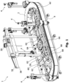
- Fig. 1 shows a representation of a conveying system 1 (hereinafter "system") according to an embodiment of the invention.
- the system 1 comprises a stationary track 2 which is formed as a loop (oblong circuit) and on which a plurality of carriages 4 are arranged so that they can be conveyed while being held along the track 2.
- the track 2 has a modular form and comprises electric windings which can be energised to create a magnetic field.
- Each carriage 4 comprises e.g. a magnet 6 which can interact with the magnetic field.
- the track 2 and each carriage 4 forms a respective linear synchronous motor, the track 2 forming a common stator and each carriage 4 forming a rotor, as is known in the art.
- the carriages 4 can be conveyed or be kept stationary at all portions of the track 2, by means of the linear motor.
- each carriage 4 has a turntable-like receptacle 12 for receiving a respective product 10.
- the receptacle 12 is plate-like and rotatably supported by a non-rotating main body 14 of the carriage, such as via a bearing.
- the axis of rotation is vertical.
- the receptacle 12 has a top surface suited for receiving a particular product.
- a lower part of the main body 14 comprises the aforementioned magnet 6 and a plurality of wheels 8 for engaging with raceways on the track 2.
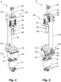
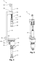
- the carriage 4 has a product-holding mechanism 18 configured to urge a product 10 ( Fig. 5 ) to be received by the receptacle 12 towards the receptacle 12.
- the product-holding mechanism 18 is provided on the carriage 4 at a predetermined height above the receptacle 12 by being supported by a vertical beam 19 and comprises a jack 20 which can move within a predetermined range in the vertical direction.
- the jack 20 is a columnar member with a lower portion 28 having a closed end.
- the vertical movement is enabled by means of a bearing having a limited stroke corresponding to the predetermined range.
- the jack 20 is attached to the lower end of a rod 22 which is slidingly received in a though-hole in a bearing block 24 fixed to the upper end of the vertical beam 19.
- the rod 22 and the bearing block 24 form a linear plain bearing.
- the jack 20 is spring-loaded so as to be urged downward (parallel to the rotation axis of the receptacle 12) within the predetermined range, by means of two upper compression springs 26 provided on respective linear guides on either side of the rod 22.
- the jack 20 is rotatable relative to the rod 22 via a rotational thrust bearing 27.
- the lower portion 28 may be rotatably attached to the rest of the jack 20.
- the carriage 4 is configured to hold a product 10 between the receptacle 12 and the jack 20 (see Fig. 5 ), while the lower portion 28 of the jack 20 is in contact with a top surface of the product 10 to urge it toward the receptacle 12. A product 10 is thus firmly holdable and releasable by the carriage 4.
- An upper cam roller 32 is rotatably fixed to the upper end of the rod 22 and is configured to engage with an upper cam surface 34 ( Fig. 1 ) which is fixed relative to the track 2.
- the upper cam roller 32 moves upward, by being urged by the upper cam surface 34, and so the rod 22 is also urged upwards to overcome the spring load from the upper compression springs 26 which become compressed.
- the rod 22 slides upwards in the bearing block 24. In this way the urging load on any product 10 from the carriage 4 can be released.
- the upper cam roller 32 disengages from the upper cam surface 34 the rod 22 is urged by the upper compression springs 26 so the product 10 is again firmly held.
- An intermediate cam roller 36 is rotatably fixed to the bearing block 24 and is configured to engage with an intermediate cam surface 38 which is fixed relative to the track 2.
- the intermediate cam roller 36 makes contact with the intermediate cam surface 38 without significant urging.
- the intermediate cam roller 36 need not be configured to move up or down, nor be spring-loaded.
- the carriage 4 is reliably guidingly supported by the contact between the intermediate cam roller 36 and the intermediate cam surface 38. So any upward urging forces from the upper cam surface 34 to the upper cam roller 32 are isolated to the product-holding mechanism 18 and so not transferred to the rest of the carriage.
- the upper 34 and intermediate 38 cam surfaces are executed as a single beam-like member that comprises guide walls to control lateral movement of the upper cam rollers 32.
- the intermediate cam rollers 36 may be guided correspondingly.
- the carriage 4 comprises a pulley 40 rotatably supported by the main body 14 to rotate with the receptacle 12.
- the receptacle 12 and the pulley 40 may be supported by a common rotational bearing (not shown) which can support thrust loads.
- the pulley 40 has an outer peripheral surface provided with teeth.
- the vertical beam 19 is fixed at its lower end to the main body 14 of the carriage 4 so that it does not rotate with the receptacle 12 and pulley 40.
- the pulley 40 is at least partially covered by a housing 42.
- the carriage 4 is provided with a restricting mechanism 46 which restricts (and preferably locks) the rotation of the receptacle 12.
- the restricting mechanism 46 has a pad 48 which is fixed to the end of a pad-holding member 50.
- the pad-holding member 50 is spring-loaded (by means of a lower spring 52) so as to urge the pad 48 against an upper surface of the pulley 40.
- the pulley 40 and therefore also the receptacle 12 can be restricted from rotating by means of the frictional force between the pad 48 and the pulley 40.
- the contacting surfaces of the pad 48 and the pulley 40 may be surface-treated to provide a suitable coefficient of friction.
- the restricting mechanism 46 may have a friction clutch or dog clutch.
- the pad-holding member 50 is connected to a lower cam roller 54 which is configured to engage with a lower cam surface 56 fixed relative to the track 2.
- the lower cam roller 54 engages with the lower cam surface 56 (by means of the carriage 4 moving into the region of the track where the lower cam surface 56 is provided) the lower cam roller 54 is urged upward which compresses the lower spring 52.
- the pad 48 moves away from the pulley 40 and the restriction on the rotation of the pulley 40 is released.
- the lower cam roller 54 disengages from the lower cam surface 56 the pad 48 is urged down under the returning force of the lower spring 52 so that the pulley 40 and receptacle 12 are restricted from rotating.
- Fig. 6 shows a part of the system in operation.
- the system 1 comprises a receptacle-rotating mechanism for orienting the receptacle 12 of each carriage 4.
- the receptacle-rotating mechanism is provided beside the track 2 and comprises a toothed belt 60 engaging a series of driven belt-pulleys 62 and a servo-motor-operated driving belt-pulley 64 which has teeth engaging the teeth of the belt 60.
- the belt-pulley axes are vertical and fixed relative to the track 2 .
- the belt-pulleys 62, 64 and belt 60 are arranged so that a straight part of the belt 60 extends alongside a region (hereinafter "belt region") of the track 2.
- the pulley 40 of each carriage 4 can pass though the belt region.
- the teeth of the belt 60 face the track 2.
- the belt 60 supported on its side facing away from the track 2 by a support beam 66 having a flat surface.
- the upper and lower extents of the flat surface are provided with two wall portions 68 extending away from the flat surface so that the belt 60 is received between these with a clearance.
- the support beam 66 guides and supports the portion of the belt 60 in the belt region.
- the belt 60 may have teeth on both sides and the belt-pulleys 62, 64 may each have teeth. Alternatively the belt 60 and the pulleys 40, 62, 64 may have no teeth.
- the belt 60 may be driven at a constant advancing speed.
- the belt 60 is an example of a receptacle-rotating member. Other examples include a roller chain or rotating corkscrew-like member. In the case of a roller chain each pulley 40, 62, 64 may be provided as a sprocket.
- the pulley 40 and receptacle 12 rotate in the other direction. In both cases the speed of rotation of the pulley 40 and receptacle 12 is proportional to the difference between the conveyance speed of the carriage 4 and the advancing speed of the belt 60. If the conveyance speed of the carriage 4 is equal to the advancing speed of the belt 60, the carriage 4 is conveyed without rotation of the pulley 40 and receptacle 12, and in this case the engagement between the belt 60 and the pulley 40 has a function of restricting rotation of the pulley 40 and receptacle 12. The carriage 4 need not have a constant speed. Controlling the conveyance of the carriage may include any of generating, stopping, increasing the speed of, and decreasing the speed of, the conveyance.
- the conveyance speed of the carriage 4 can be set to match the advancing speed, in particular at the time when it enters and/or leaves the belt region.
- the receptacle 12 can be set into rotation (and the restricting mechanism 46 is released) only after the carriage 4 has entered and travelled a predetermined distance in the belt region. So the ends of the belt region represent transition phases wherein shock loads resulting from sudden changes in receptacle rotation are reduced.
- the start and end positions of the lower cam surface 56 can be adjusted accordingly.
- any receptacle 12 in the belt region can be controlled by adjusting the conveyance of the respective carriage 4 independently of the orientations of the other receptacles 12 or conveyance speeds of the other carriages 4.
- the belt movement does not influence the conveyance speeds.
- the receptacle-rotating mechanism does not convey the carriage 4 at any time.
- a transmission (e.g. an epicyclic gearbox) may be provided between the receptacle 12 and the pulley 40 so that these can relatively rotate with a predetermined gear ratio other than 1:1.
- the pad 48 may alternatively or in addition contact the receptacle 12 or a moving element of any transmission.
- products 10 which are not yet received on the carriages 4 approach the track 2 from an upstream production stage, such as by means of a separate conveyor (not shown).
- the products 10 are sequentially transferred to respective carriages 4 by means known in the art such as an infeeding star wheel (not shown) which may be provided at a straight portion of the track 2 away from the belt 60, said straight portion being parallel to the separate conveyor.
- each carriage 4 operates accordingly. Shortly before a product 10 is transferred to the carriage 4 the state of the product-holding mechanism 18 changes from the held to the released state. Shortly after the product 10 is received by the receptacle 12, the state of the product-holding mechanism 18 changes to the hold state. The releasing and holding by the product-holding mechanism 18 is achieved by providing the upper 34 and intermediate 38 cam surfaces in the region of the track 2 where the product 10 is transferred.
- the product 10 is reliably held on its carriage 4 by the product-holding mechanism 18 at all other regions on the track 2.
- this may be understood to include the carriage 4 being coupled to the track 2 so as to be conveyed along the track 2.
- the carriage 4 carrying the firmly held product 10 is conveyed (e.g. counterclockwise) toward the belt region, whereupon the carriage's pulley 40 engages with the belt 60, and the restricting mechanism 46 releases the pad 48 from the pulley 40. While the carriage 4 is in the belt region, the rotational orientation of the receptacle 12 is dependent on the speed of conveyance of the carriage 4 and the advancing speed or the belt 60, as described above.
- the belt region is configured so that various (not-shown) production devices known in the art can be arranged alongside the belt region on the opposite side of the track 2 to the belt 60, such as on the opposite side of the carriage 4 to the belt 60.
- Such production stations may comprise one or more labelling devices.
- a carriage 4 is conveyed past a labelling device, its conveyance speed relative to the advancing speed of the belt 60 can be controlled to create an optimum rotation of the product 10 during the labelling process.
- Various types of label can be applied to various shapes of product 10. For example a wraparound label covering the circumference of a bottle having circular section can be applied. Alternatively a label covering a predetermined part of the circumference of a bottle of elliptical section (e.g. 10 in Figs. 5 and 6 ) can be applied.
- the system 1 may be configured to set a predetermined rotational orientation of the product 10 at the time that the product 10 approaches the labelling device.
- an optical sensor (not shown) may be provided at a predetermined position in the belt region which is upstream of the labelling device.
- the carriage 4 can be stopped at the optical sensor (not shown), whereupon the belt 60 which advances at a constant speed effects a rotation of the product 10.
- An index mark provided in a predetermined place on the circumference of the product 10 can be detected by the optical sensor, and the instantaneous rotational orientation of the product 10 can be determined.
- the subsequent conveyance speed and rotation of the receptacle 12 can be set in accordance with the measured instantaneous orientation.
- a marking device may be provided at a second predetermined position in the belt region and the system 1 can be configured to mark (e.g. by laser) the product 10 at a predetermined position in the circumferential direction of its outer surface, in accordance with a determined orientation.
- the product 10 may be rotated or may be stationary during the marking.
- production devices that make use of the advantages of the system 1 include sealing devices such as bottle top applicators.
- the carriage 4 is subsequently conveyed out of the belt region to a downstream portion of the track 2 (the urging of the pad 48 is reapplied) where the product 10 can be transferred from the carriage 4 to the aforementioned separate conveyor by means known in the art such as an outfeeding star wheel (not shown).
- the products 10 may be transferred from the track 2 at a straight portion of the track 2 away from the belt 60, the straight portion being parallel to the separate conveyor.
- the system 1 can ensure that each product 10 has a predetermined orientation at a predetermined position on the track 2 to ensure the correct function of any star wheel and/or efficient packing of a plurality of products.
- the carriages 4 need not be connected with an electricity supply via cables, for example. There is no need to provide a receptacle-rotating device on each carriage 4, such as an electric motor on each carriage, or on an auxiliary carriage that follows or leads each carriage.
- the belt 60 engages with the receptacle 12 via the pulley 40, thus imparting a rotation movement on the receptacle 12. So rotation and conveyance of the products 10 is not by direct tangential forces on the product's surface. Non-circular products 10 can be easily rotated.
- the carriage 4 makes belt contact on only one side (being the carriage's track-facing side). This ensures that conveyance is independent of any belt movement. The conveyance of the carriage 4 is by means of a conveyance force acting on the main body 14, from below the receptacle 12.
- the magnet 6 is laterally urged toward the laterally facing track 2 by a magnetic force, so when required the carriage 4 can be easily removed from the track 2 by pulling it away from the track 2 .
- Wheels 8 above and below the magnet 6 keep the magnet 6, and therefore the carriage 4, a fixed distance from the track.
- the carriage 4 can be securely held and smoothly conveyed since the magnet 6 and wheels 8 are provided below the receptacle 12 and the pulley 40, in particular as the lowermost parts of the carriage 4.
- any or all of the track 2, the receptacle-rotating member 60, and the vertical beam (structural member) 19 may be on the same side of the carriage 4 with respect to the axis of rotation of the receptacle 12. So there is more space on the other side of the carriage 4 for production devices.
- the maximum extent of the track 2 need not be greater than the maximum extent of the carriage 4, in the lateral direction. So when the track 2 does not extend further to the other side than the carriage 4, in the lateral direction, this leads to a more compact construction as well as more space for production devices.
- the track 2 may be supported by a structure, for example so as to be fixed at ground level, or alternatively so as to be raised to a given height above the ground.
- the support of the track 2 may be from any of below, above and to the sides of the track, When viewed along the conveying direction (such as with the track profile shown in cross-section).
- the track 2 is supported (such as on one of its sides), wherein parts or all of the support are on the same side of the axis of rotation of the receptacle 12 that the receptacle-rotating member 60 is provided on. This leads to more space for production devices on the opposite side of the axis.
- the belt region is straight.
- the belt 60 may be provided alternatively or in addition on a curved part of the track 2.
- the belt 60 may be guided by a pulley having an axis of rotation coaxial with the centre of a curve radius.
- the belt 60 may be provided over the entirety of the track path. Alternatively two or more belts 60 may be provided along the track 2.
- More than one carriage 4 can be in the belt region at the one time. Alternatively the carriages 4 pass through the belt region one at a time.
- each carriage 4 is independent of the conveyance speeds of the other carriages 4, it is to be understood that the speeds of the carriages 4 can be adjusted individually so that the pitch between a pair of carriages 4 can be changed, to the extent that the carriages 4 do not collide or overtake each other.
- the term "speed" may include zero speed.
- the advancing speed of the belt 60 is non-zero and constant and the conveyance speeds of the carriages 4 are independently controlled to achieve a desired orientation or rate of change of orientation of each receptacle 12.
- the conveyance direction may be the same as the advancing direction of the belt 60. When the conveyance direction opposes the advancing direction, the relative directions can be accounted for by considering the velocity differences of the moving elements.
- the track 2 is provided below the carriage.
- the track 2 may be provided above the carriage 4 so that the carriage 4 and products 10 are supported by the track 2 from above.
- the receptacle 12 may face upwards or downwards.
- the upper 26 and lower 52 springs may be configured as coil springs or as any suitable resilient members such as ones known in the art.
- the product-holding mechanism 18 need not urge the products 10 from above, but may urge the products 10 from its sides, for example.
- the conveyance speeds of each carriage 4 and the advancing speed of the belt 60 may be controlled by a control unit, which can preferably control other units such as any star wheels and/or labelling devices, according to a PLC program.
- the shape of the receptacle 12 and the product-holding mechanism 18, especially the lower portion 28 of the jack 20, may be chosen to suit a particular product. Different products can be processed by changing or adapting these two.
- the receiving face of the receptacle may have a protrusion and/or a cutout.
- the height of the upper 34 and intermediate 38 cam surfaces can be adjusted in accordance with the height of a particular product, by means of a mechanism driven by a motor 39 shown in Fig. 1 .
- By selecting a suitable stroke of the product-holding mechanism 18, the carriage 4 can accommodate a range of product sizes.
- the track 2 may be provided with a second loop for performing offline changes to the carriages 4.
- the advancing speed of the receptacle-rotating member may be uniform at all places on the receptacle-rotating member.
- each carriage, via its receptacle, with the receptacle-rotating member may be direct or indirect.
Landscapes
- Engineering & Computer Science (AREA)
- Mechanical Engineering (AREA)
- Control Of Conveyors (AREA)
- Intermediate Stations On Conveyors (AREA)
- Specific Conveyance Elements (AREA)
- Non-Mechanical Conveyors (AREA)
- Attitude Control For Articles On Conveyors (AREA)
Claims (14)
- Fördersystem, umfassendeine Schiene (2),eine Vielzahl von auf der Schiene zu befördernden Schlitten (4), wobei jeder Schlitten umfasst: einen Hauptkörper (14), der entlang der Schiene gehalten wird; eine Aufnahme (12), die drehbar von dem Hauptkörper (14) gestützt wird und so konfiguriert ist, dass sie ein Produkt (10) aufnimmt, und eine Riemenscheibe (40), die drehbar von dem Hauptkörper (14) gestützt wird, um sich mit der Aufnahme (12) zu drehen, undein Aufnahmedrehelement (60), das mit einer definierten Vorschubgeschwindigkeit entlang eines Bereichs, der an mindestens einem Abschnitt der Schiene (2) vorgesehen ist, vorschiebbar ist, wobei das Aufnahmedrehelement (60) eines der Folgenden ist: ein Riemen, eine Rollenkette und ein drehbares korkenzieherartiges Teil, wobeijeder Schlitten (4) über seine Riemenscheibe (40) mit dem Aufnahmedrehelement (60) in Eingriff sein kann, wobei der Eingriff davon abhängig ist, dass sich der jeweilige Schlitten (4) in dem Bereich befindet, wobeidie Drehorientierung der Aufnahme (12) jedes Schlittens (4) relativ zum Hauptkörper (14) des Schlittens durch Steuern einer Differenz zwischen einer Fördergeschwindigkeit des Schlittens (4) und der Vorschubgeschwindigkeit des Aufnahmedrehelements (60) steuerbar ist, dadurch gekennzeichnet, dassdas Fördersystem so konfiguriert ist, dass es die Drehorientierung des Behälters (12) jedes Schlittens (4) relativ zum Hauptkörper des Schlittens (14) durch Steuern der Fördergeschwindigkeit jedes Schlittens in dem Bereich unabhängig von den Fördergeschwindigkeiten der anderen Schlitten (4) steuert.
- Fördersystem nach Anspruch 1, wobei die Fördergeschwindigkeit jedes Schlittens (4) unabhängig von der Vorschubgeschwindigkeit ist.
- Fördersystem nach einem der vorhergehenden Ansprüche, umfassendmindestens einen Sensor zum Bestimmen einer Drehorientierung eines auf einem Behälter (12) aufzunehmenden Produkts (10), wobeidas Fördersystem so konfiguriert ist, dass es die Drehorientierung des Produkts (10) bestimmt und optional die Fördergeschwindigkeit des Schlittens (4) des Behälters auf der Grundlage eines Signals von dem Sensor anpasst.
- Fördersystem nach einem der vorhergehenden Ansprüche, wobeiwenigstens ein Schlitten (4) einen Begrenzungsmechanismus (46) aufweist, der so konfiguriert ist, dass er die Drehung des Behälters (12) relativ zum Hauptkörper (14) in Abhängigkeit von der Position oder den Positionen des Schlittens (4) auf der Schiene (2) begrenzt, und wobei vorzugsweiseder Begrenzungsmechanismus (46) wenigstens dann freigegeben wird, wenn sich der Schlitten (4) in dem Bereich befindet.
- Fördersystem nach einem der vorhergehenden Ansprüche, wobeidas Aufnahmedrehelement (60) ein mit der Riemenscheibe (40) in Eingriff bringbarer Riemen (60) ist und vorzugsweisedie Beförderung des Schlittens (4) mittels einer Kraftübertragung auf den Hauptkörper (14) erfolgt, wobei der Übertragungsweg zum Hauptkörper die Riemenscheibe umgeht.
- Fördersystem nach einem der vorhergehenden Ansprüche, wobei
wenigstens ein Schlitten (4) einen Produkthaltemechanismus (18) umfasst, der so konfiguriert ist, dass er ein von der Aufnahme (12) aufzunehmendes Produkt (10) in Richtung der Aufnahme (12) drückt, wobei der Druck in Abhängigkeit von einer Position oder von Positionen des Schlittens (4) auf der Schiene (2) freigegeben wird. - Fördersystem nach einem der vorhergehenden Ansprüche, das so konfiguriert ist, dass es einen Abstand zwischen Schlitten (4) durch Steuerung der Fördergeschwindigkeiten der Schlitten (4) unabhängig voneinander anpasst.
- Fördersystem nach einem der vorhergehenden Ansprüche, das so konfiguriert ist, dass es die Fördergeschwindigkeit eines Schlittens (4) variiert, wenn sich der Schlitten (4) in dem Bereich befindet.
- Fördersystem nach einem der vorhergehenden Ansprüche, das so konfiguriert ist, dass es die Drehung des Behälters (12) des Schlittens stoppt, indem der Schlitten (4) in zumindest einem Teil des Bereichs mit einer Geschwindigkeit gefördert wird, die der Vorschubgeschwindigkeit entspricht.
- Fördersystem nach einem der vorhergehenden Ansprüche, wobei für jeden Schlitten (4): in Förderrichtung des Schlittens gesehen die gesamte Schiene (2) und Teile oder das gesamte Aufnahmedrehelement (60) auf derselben Seite in Bezug auf die Drehachse der Aufnahme (12) angeordnet sind, wenn der Schlitten in Eingriff ist.
- Fördersystem nach einem der vorhergehenden Ansprüche, wobei für jeden Schlitten (4): in Förderrichtung des Schlittens gesehen das Aufnahmedrehelement (60) auf einer Seite in Bezug auf die Drehachse des Behälters (12) vorgesehen ist und die Schiene (2) auf derselben Seite abgestützt ist, wenn der Schlitten (4) in Eingriff ist.
- Fördersystem nach einem der vorhergehenden Ansprüche, wobei für jeden Schlitten (4):der Hauptkörper (14) ein Strukturelement (19) umfasst, das sich von der Aufnahme (12) weg und parallel zur Drehachse der Aufnahme erstreckt, unddas Strukturelement (19) und das Aufnahmedrehelement (60) in Förderrichtung des Schlittens (4) gesehen auf derselben Seite in Bezug auf die Drehachse der Aufnahme (12) angeordnet sind, wenn der Schlitten (4) in Eingriff ist.
- Verfahren zum Fördern einer Vielzahl von Produkten (10) unter Verwendung des Fördersystems nach einem der vorhergehenden Ansprüche, umfassendAnordnen jedes Produkts auf dem Behälter (12) eines entsprechenden Schlittens (4),Bestimmen einer Solldrehorientierung jedes Produkts,Erreichen der Solldrehorientierungen während des Förderns der Schlitten (4) durch den Bereich durch Steuern der Vorschubgeschwindigkeit und der Fördergeschwindigkeit jedes Schlittens in dem Bereich.
- Verfahren nach Anspruch 13, umfassend
das Bestimmen der Drehorientierung jedes Produkts (10) mittels eines Sensors.
Applications Claiming Priority (2)
| Application Number | Priority Date | Filing Date | Title |
|---|---|---|---|
| LU101702A LU101702B1 (en) | 2020-03-25 | 2020-03-25 | Conveying system and method of conveying a plurality of products |
| PCT/IB2021/052279 WO2021191753A1 (en) | 2020-03-25 | 2021-03-18 | Conveying system and method of conveying a plurality of products |
Publications (3)
| Publication Number | Publication Date |
|---|---|
| EP4126718A1 EP4126718A1 (de) | 2023-02-08 |
| EP4126718B1 true EP4126718B1 (de) | 2025-05-21 |
| EP4126718C0 EP4126718C0 (de) | 2025-05-21 |
Family
ID=70057202
Family Applications (1)
| Application Number | Title | Priority Date | Filing Date |
|---|---|---|---|
| EP21712910.5A Active EP4126718B1 (de) | 2020-03-25 | 2021-03-18 | Fördersystem und verfahren zum fördern einer vielzahl von produkten |
Country Status (7)
| Country | Link |
|---|---|
| US (1) | US12077391B2 (de) |
| EP (1) | EP4126718B1 (de) |
| JP (1) | JP7696358B2 (de) |
| ES (1) | ES3034236T3 (de) |
| LU (1) | LU101702B1 (de) |
| PL (1) | PL4126718T3 (de) |
| WO (1) | WO2021191753A1 (de) |
Families Citing this family (2)
| Publication number | Priority date | Publication date | Assignee | Title |
|---|---|---|---|---|
| WO2024165982A1 (en) * | 2023-02-07 | 2024-08-15 | Ronchi Mario S.P.A. | Apparatus and method for sorting randomly fed closing elements of different types or formats |
| EP4610182A1 (de) * | 2024-02-28 | 2025-09-03 | ATS Corporation | Hochgeschwindigkeitsetikettierung von gegenständen |
Family Cites Families (10)
| Publication number | Priority date | Publication date | Assignee | Title |
|---|---|---|---|---|
| US3944455A (en) * | 1973-09-27 | 1976-03-16 | Compac Corporation | Labelling system and cassette label applicator usable therewith |
| JP4873287B2 (ja) * | 2005-06-29 | 2012-02-08 | 澁谷工業株式会社 | 容器処理装置 |
| US9085420B2 (en) * | 2013-03-26 | 2015-07-21 | The Procter & Gamble Company | Orienting apparatus and method |
| JP2015003771A (ja) | 2013-06-19 | 2015-01-08 | 株式会社フジシールインターナショナル | ワーク位置決め装置、および、これを備えたワーク処理システム |
| DE102014107427B4 (de) * | 2014-05-27 | 2018-04-26 | Khs Gmbh | Vorrichtung und Verfahren zum gesteuerten Ausrichten und/oder gesteuerten Drehen von Behältern |
| ITUB20159535A1 (it) * | 2015-12-14 | 2017-06-14 | Makro Labelling Srl | Macchina di convogliamento per contenitori |
| AT519829A1 (de) | 2017-04-04 | 2018-10-15 | B & R Ind Automation Gmbh | Verfahren zum Betreiben eines Langstatorlinearmotors |
| DE102017119084A1 (de) * | 2017-08-21 | 2019-02-21 | Beckhoff Automation Gmbh | System und Verfahren zum Ausrichten eines Objekts |
| IT201700100503A1 (it) * | 2017-09-07 | 2019-03-07 | Makro Labelling Srl | Macchina per il convogliamento di contenitori |
| IT201800006629A1 (it) * | 2018-06-25 | 2019-12-25 | Apparato di convogliamento e macchina di etichettaggio provvista di tale apparato di convogliamento |
-
2020
- 2020-03-25 LU LU101702A patent/LU101702B1/en active IP Right Grant
-
2021
- 2021-03-18 PL PL21712910.5T patent/PL4126718T3/pl unknown
- 2021-03-18 US US17/913,312 patent/US12077391B2/en active Active
- 2021-03-18 ES ES21712910T patent/ES3034236T3/es active Active
- 2021-03-18 WO PCT/IB2021/052279 patent/WO2021191753A1/en not_active Ceased
- 2021-03-18 JP JP2022555161A patent/JP7696358B2/ja active Active
- 2021-03-18 EP EP21712910.5A patent/EP4126718B1/de active Active
Also Published As
| Publication number | Publication date |
|---|---|
| EP4126718A1 (de) | 2023-02-08 |
| JP2023528120A (ja) | 2023-07-04 |
| US12077391B2 (en) | 2024-09-03 |
| WO2021191753A1 (en) | 2021-09-30 |
| US20230110445A1 (en) | 2023-04-13 |
| JP7696358B2 (ja) | 2025-06-20 |
| PL4126718T3 (pl) | 2025-07-21 |
| EP4126718C0 (de) | 2025-05-21 |
| ES3034236T3 (en) | 2025-08-14 |
| LU101702B1 (en) | 2021-09-27 |
Similar Documents
| Publication | Publication Date | Title |
|---|---|---|
| EP4126718B1 (de) | Fördersystem und verfahren zum fördern einer vielzahl von produkten | |
| US6527102B2 (en) | Installation for forming batches of articles | |
| US4676361A (en) | Troughing conveyors for carton or bag orienting and conveying | |
| EP2199233A1 (de) | Systeme und Verfahren zur Bereitstellung einer Förderanlage mit verbessertem Zeitintervall | |
| US8776985B2 (en) | Method and an apparatus for transporting containers or packs of containers | |
| KR101423940B1 (ko) | 컨베이어 | |
| US20120018282A1 (en) | Transport apparatus | |
| US8893873B1 (en) | Material handling feed table | |
| DK168114B1 (da) | Apparat til tilfoersel af ark eller emner til et stabelmagasin | |
| AU2002353110B2 (en) | Selection system | |
| US5353908A (en) | Suspended conveyance apparatus | |
| AU2011262134A1 (en) | Document transporter | |
| MXPA03001685A (es) | Metodo y apara para cambiar la orientacion de piezas y trabajo alrededor de un eje en angulo para una decoradora. | |
| US7240784B2 (en) | Selection system | |
| EP3085645B1 (de) | Vorrichtung zum transportieren von gegenständen | |
| US4874079A (en) | Article transferring conveying system | |
| CN109485002A (zh) | 一种吹瓶灌装一体机及其中间转换装置 | |
| CN217861505U (zh) | 一种物料到位检测装置 | |
| US6213185B1 (en) | Feeder for outserts and other articles | |
| CN112875236A (zh) | 一种稳定精准夹瓶装置及控制方法 | |
| GB2410734A (en) | Installation for placing sleeves on products such as bottles | |
| EP4306452A1 (de) | ???????????????????????????????????????????vorrichtung | |
| GB2233620A (en) | Roller conveyor | |
| EP4045416A1 (de) | Fördervorrichtung zum fördern von gegenständen und verfahren zum etikettieren von gegenständen | |
| JP3817511B2 (ja) | 物品受渡装置 |
Legal Events
| Date | Code | Title | Description |
|---|---|---|---|
| STAA | Information on the status of an ep patent application or granted ep patent |
Free format text: STATUS: UNKNOWN |
|
| STAA | Information on the status of an ep patent application or granted ep patent |
Free format text: STATUS: THE INTERNATIONAL PUBLICATION HAS BEEN MADE |
|
| PUAI | Public reference made under article 153(3) epc to a published international application that has entered the european phase |
Free format text: ORIGINAL CODE: 0009012 |
|
| STAA | Information on the status of an ep patent application or granted ep patent |
Free format text: STATUS: REQUEST FOR EXAMINATION WAS MADE |
|
| 17P | Request for examination filed |
Effective date: 20220527 |
|
| AK | Designated contracting states |
Kind code of ref document: A1 Designated state(s): AL AT BE BG CH CY CZ DE DK EE ES FI FR GB GR HR HU IE IS IT LI LT LU LV MC MK MT NL NO PL PT RO RS SE SI SK SM TR |
|
| DAV | Request for validation of the european patent (deleted) | ||
| DAX | Request for extension of the european patent (deleted) | ||
| GRAP | Despatch of communication of intention to grant a patent |
Free format text: ORIGINAL CODE: EPIDOSNIGR1 |
|
| STAA | Information on the status of an ep patent application or granted ep patent |
Free format text: STATUS: GRANT OF PATENT IS INTENDED |
|
| INTG | Intention to grant announced |
Effective date: 20241217 |
|
| GRAS | Grant fee paid |
Free format text: ORIGINAL CODE: EPIDOSNIGR3 |
|
| GRAA | (expected) grant |
Free format text: ORIGINAL CODE: 0009210 |
|
| STAA | Information on the status of an ep patent application or granted ep patent |
Free format text: STATUS: THE PATENT HAS BEEN GRANTED |
|
| AK | Designated contracting states |
Kind code of ref document: B1 Designated state(s): AL AT BE BG CH CY CZ DE DK EE ES FI FR GB GR HR HU IE IS IT LI LT LU LV MC MK MT NL NO PL PT RO RS SE SI SK SM TR |
|
| REG | Reference to a national code |
Ref country code: GB Ref legal event code: FG4D |
|
| REG | Reference to a national code |
Ref country code: CH Ref legal event code: EP |
|
| REG | Reference to a national code |
Ref country code: DE Ref legal event code: R096 Ref document number: 602021031097 Country of ref document: DE |
|
| REG | Reference to a national code |
Ref country code: IE Ref legal event code: FG4D |
|
| U01 | Request for unitary effect filed |
Effective date: 20250610 |
|
| U07 | Unitary effect registered |
Designated state(s): AT BE BG DE DK EE FI FR IT LT LU LV MT NL PT RO SE SI Effective date: 20250617 |
|
| REG | Reference to a national code |
Ref country code: ES Ref legal event code: FG2A Ref document number: 3034236 Country of ref document: ES Kind code of ref document: T3 Effective date: 20250814 |
|
| PG25 | Lapsed in a contracting state [announced via postgrant information from national office to epo] |
Ref country code: NO Free format text: LAPSE BECAUSE OF FAILURE TO SUBMIT A TRANSLATION OF THE DESCRIPTION OR TO PAY THE FEE WITHIN THE PRESCRIBED TIME-LIMIT Effective date: 20250821 Ref country code: GR Free format text: LAPSE BECAUSE OF FAILURE TO SUBMIT A TRANSLATION OF THE DESCRIPTION OR TO PAY THE FEE WITHIN THE PRESCRIBED TIME-LIMIT Effective date: 20250822 |
|
| PG25 | Lapsed in a contracting state [announced via postgrant information from national office to epo] |
Ref country code: HR Free format text: LAPSE BECAUSE OF FAILURE TO SUBMIT A TRANSLATION OF THE DESCRIPTION OR TO PAY THE FEE WITHIN THE PRESCRIBED TIME-LIMIT Effective date: 20250521 |
|
| PG25 | Lapsed in a contracting state [announced via postgrant information from national office to epo] |
Ref country code: RS Free format text: LAPSE BECAUSE OF FAILURE TO SUBMIT A TRANSLATION OF THE DESCRIPTION OR TO PAY THE FEE WITHIN THE PRESCRIBED TIME-LIMIT Effective date: 20250821 |
|
| PG25 | Lapsed in a contracting state [announced via postgrant information from national office to epo] |
Ref country code: IS Free format text: LAPSE BECAUSE OF FAILURE TO SUBMIT A TRANSLATION OF THE DESCRIPTION OR TO PAY THE FEE WITHIN THE PRESCRIBED TIME-LIMIT Effective date: 20250921 |