EP4126510B1 - Extraktionssystem für eine vorrichtung zur schichtweisen bildung von dreidimensionalen objekten und zugehörige verfahren und steuerung - Google Patents
Extraktionssystem für eine vorrichtung zur schichtweisen bildung von dreidimensionalen objekten und zugehörige verfahren und steuerung Download PDFInfo
- Publication number
- EP4126510B1 EP4126510B1 EP21722974.9A EP21722974A EP4126510B1 EP 4126510 B1 EP4126510 B1 EP 4126510B1 EP 21722974 A EP21722974 A EP 21722974A EP 4126510 B1 EP4126510 B1 EP 4126510B1
- Authority
- EP
- European Patent Office
- Prior art keywords
- primary
- flow
- gas
- working space
- inlet
- Prior art date
- Legal status (The legal status is an assumption and is not a legal conclusion. Google has not performed a legal analysis and makes no representation as to the accuracy of the status listed.)
- Active
Links
Images




Classifications
-
- B—PERFORMING OPERATIONS; TRANSPORTING
- B29—WORKING OF PLASTICS; WORKING OF SUBSTANCES IN A PLASTIC STATE IN GENERAL
- B29C—SHAPING OR JOINING OF PLASTICS; SHAPING OF MATERIAL IN A PLASTIC STATE, NOT OTHERWISE PROVIDED FOR; AFTER-TREATMENT OF THE SHAPED PRODUCTS, e.g. REPAIRING
- B29C64/00—Additive manufacturing, i.e. manufacturing of three-dimensional [3D] objects by additive deposition, additive agglomeration or additive layering, e.g. by 3D printing, stereolithography or selective laser sintering
- B29C64/30—Auxiliary operations or equipment
- B29C64/364—Conditioning of environment
-
- B—PERFORMING OPERATIONS; TRANSPORTING
- B08—CLEANING
- B08B—CLEANING IN GENERAL; PREVENTION OF FOULING IN GENERAL
- B08B15/00—Preventing escape of dirt or fumes from the area where they are produced; Collecting or removing dirt or fumes from that area
-
- B—PERFORMING OPERATIONS; TRANSPORTING
- B29—WORKING OF PLASTICS; WORKING OF SUBSTANCES IN A PLASTIC STATE IN GENERAL
- B29C—SHAPING OR JOINING OF PLASTICS; SHAPING OF MATERIAL IN A PLASTIC STATE, NOT OTHERWISE PROVIDED FOR; AFTER-TREATMENT OF THE SHAPED PRODUCTS, e.g. REPAIRING
- B29C64/00—Additive manufacturing, i.e. manufacturing of three-dimensional [3D] objects by additive deposition, additive agglomeration or additive layering, e.g. by 3D printing, stereolithography or selective laser sintering
- B29C64/10—Processes of additive manufacturing
- B29C64/141—Processes of additive manufacturing using only solid materials
- B29C64/153—Processes of additive manufacturing using only solid materials using layers of powder being selectively joined, e.g. by selective laser sintering or melting
-
- B—PERFORMING OPERATIONS; TRANSPORTING
- B29—WORKING OF PLASTICS; WORKING OF SUBSTANCES IN A PLASTIC STATE IN GENERAL
- B29C—SHAPING OR JOINING OF PLASTICS; SHAPING OF MATERIAL IN A PLASTIC STATE, NOT OTHERWISE PROVIDED FOR; AFTER-TREATMENT OF THE SHAPED PRODUCTS, e.g. REPAIRING
- B29C64/00—Additive manufacturing, i.e. manufacturing of three-dimensional [3D] objects by additive deposition, additive agglomeration or additive layering, e.g. by 3D printing, stereolithography or selective laser sintering
- B29C64/30—Auxiliary operations or equipment
- B29C64/386—Data acquisition or data processing for additive manufacturing
- B29C64/393—Data acquisition or data processing for additive manufacturing for controlling or regulating additive manufacturing processes
-
- B—PERFORMING OPERATIONS; TRANSPORTING
- B33—ADDITIVE MANUFACTURING TECHNOLOGY
- B33Y—ADDITIVE MANUFACTURING, i.e. MANUFACTURING OF THREE-DIMENSIONAL [3D] OBJECTS BY ADDITIVE DEPOSITION, ADDITIVE AGGLOMERATION OR ADDITIVE LAYERING, e.g. BY 3D PRINTING, STEREOLITHOGRAPHY OR SELECTIVE LASER SINTERING
- B33Y40/00—Auxiliary operations or equipment, e.g. for material handling
-
- B—PERFORMING OPERATIONS; TRANSPORTING
- B22—CASTING; POWDER METALLURGY
- B22F—WORKING METALLIC POWDER; MANUFACTURE OF ARTICLES FROM METALLIC POWDER; MAKING METALLIC POWDER; APPARATUS OR DEVICES SPECIALLY ADAPTED FOR METALLIC POWDER
- B22F10/00—Additive manufacturing of workpieces or articles from metallic powder
- B22F10/10—Formation of a green body
-
- B—PERFORMING OPERATIONS; TRANSPORTING
- B22—CASTING; POWDER METALLURGY
- B22F—WORKING METALLIC POWDER; MANUFACTURE OF ARTICLES FROM METALLIC POWDER; MAKING METALLIC POWDER; APPARATUS OR DEVICES SPECIALLY ADAPTED FOR METALLIC POWDER
- B22F10/00—Additive manufacturing of workpieces or articles from metallic powder
- B22F10/30—Process control
- B22F10/32—Process control of the atmosphere, e.g. composition or pressure in a building chamber
- B22F10/322—Process control of the atmosphere, e.g. composition or pressure in a building chamber of the gas flow, e.g. rate or direction
-
- B—PERFORMING OPERATIONS; TRANSPORTING
- B22—CASTING; POWDER METALLURGY
- B22F—WORKING METALLIC POWDER; MANUFACTURE OF ARTICLES FROM METALLIC POWDER; MAKING METALLIC POWDER; APPARATUS OR DEVICES SPECIALLY ADAPTED FOR METALLIC POWDER
- B22F10/00—Additive manufacturing of workpieces or articles from metallic powder
- B22F10/30—Process control
- B22F10/36—Process control of energy beam parameters
- B22F10/368—Temperature or temperature gradient, e.g. temperature of the melt pool
-
- B—PERFORMING OPERATIONS; TRANSPORTING
- B22—CASTING; POWDER METALLURGY
- B22F—WORKING METALLIC POWDER; MANUFACTURE OF ARTICLES FROM METALLIC POWDER; MAKING METALLIC POWDER; APPARATUS OR DEVICES SPECIALLY ADAPTED FOR METALLIC POWDER
- B22F12/00—Apparatus or devices specially adapted for additive manufacturing; Auxiliary means for additive manufacturing; Combinations of additive manufacturing apparatus or devices with other processing apparatus or devices
-
- B—PERFORMING OPERATIONS; TRANSPORTING
- B22—CASTING; POWDER METALLURGY
- B22F—WORKING METALLIC POWDER; MANUFACTURE OF ARTICLES FROM METALLIC POWDER; MAKING METALLIC POWDER; APPARATUS OR DEVICES SPECIALLY ADAPTED FOR METALLIC POWDER
- B22F12/00—Apparatus or devices specially adapted for additive manufacturing; Auxiliary means for additive manufacturing; Combinations of additive manufacturing apparatus or devices with other processing apparatus or devices
- B22F12/70—Gas flow means
-
- B—PERFORMING OPERATIONS; TRANSPORTING
- B22—CASTING; POWDER METALLURGY
- B22F—WORKING METALLIC POWDER; MANUFACTURE OF ARTICLES FROM METALLIC POWDER; MAKING METALLIC POWDER; APPARATUS OR DEVICES SPECIALLY ADAPTED FOR METALLIC POWDER
- B22F12/00—Apparatus or devices specially adapted for additive manufacturing; Auxiliary means for additive manufacturing; Combinations of additive manufacturing apparatus or devices with other processing apparatus or devices
- B22F12/90—Means for process control, e.g. cameras or sensors
-
- B—PERFORMING OPERATIONS; TRANSPORTING
- B22—CASTING; POWDER METALLURGY
- B22F—WORKING METALLIC POWDER; MANUFACTURE OF ARTICLES FROM METALLIC POWDER; MAKING METALLIC POWDER; APPARATUS OR DEVICES SPECIALLY ADAPTED FOR METALLIC POWDER
- B22F2999/00—Aspects linked to processes or compositions used in powder metallurgy
-
- B—PERFORMING OPERATIONS; TRANSPORTING
- B22—CASTING; POWDER METALLURGY
- B22F—WORKING METALLIC POWDER; MANUFACTURE OF ARTICLES FROM METALLIC POWDER; MAKING METALLIC POWDER; APPARATUS OR DEVICES SPECIALLY ADAPTED FOR METALLIC POWDER
- B22F3/00—Manufacture of workpieces or articles from metallic powder characterised by the manner of compacting or sintering; Apparatus specially adapted therefor ; Presses and furnaces
- B22F3/10—Sintering only
- B22F3/105—Sintering only by using electric current other than for infrared radiant energy, laser radiation or plasma ; by ultrasonic bonding
-
- B—PERFORMING OPERATIONS; TRANSPORTING
- B29—WORKING OF PLASTICS; WORKING OF SUBSTANCES IN A PLASTIC STATE IN GENERAL
- B29C—SHAPING OR JOINING OF PLASTICS; SHAPING OF MATERIAL IN A PLASTIC STATE, NOT OTHERWISE PROVIDED FOR; AFTER-TREATMENT OF THE SHAPED PRODUCTS, e.g. REPAIRING
- B29C64/00—Additive manufacturing, i.e. manufacturing of three-dimensional [3D] objects by additive deposition, additive agglomeration or additive layering, e.g. by 3D printing, stereolithography or selective laser sintering
-
- B—PERFORMING OPERATIONS; TRANSPORTING
- B29—WORKING OF PLASTICS; WORKING OF SUBSTANCES IN A PLASTIC STATE IN GENERAL
- B29C—SHAPING OR JOINING OF PLASTICS; SHAPING OF MATERIAL IN A PLASTIC STATE, NOT OTHERWISE PROVIDED FOR; AFTER-TREATMENT OF THE SHAPED PRODUCTS, e.g. REPAIRING
- B29C64/00—Additive manufacturing, i.e. manufacturing of three-dimensional [3D] objects by additive deposition, additive agglomeration or additive layering, e.g. by 3D printing, stereolithography or selective laser sintering
- B29C64/10—Processes of additive manufacturing
- B29C64/106—Processes of additive manufacturing using only liquids or viscous materials, e.g. depositing a continuous bead of viscous material
- B29C64/124—Processes of additive manufacturing using only liquids or viscous materials, e.g. depositing a continuous bead of viscous material using layers of liquid which are selectively solidified
- B29C64/129—Processes of additive manufacturing using only liquids or viscous materials, e.g. depositing a continuous bead of viscous material using layers of liquid which are selectively solidified characterised by the energy source therefor, e.g. by global irradiation combined with a mask
- B29C64/135—Processes of additive manufacturing using only liquids or viscous materials, e.g. depositing a continuous bead of viscous material using layers of liquid which are selectively solidified characterised by the energy source therefor, e.g. by global irradiation combined with a mask the energy source being concentrated, e.g. scanning lasers or focused light sources
-
- B—PERFORMING OPERATIONS; TRANSPORTING
- B33—ADDITIVE MANUFACTURING TECHNOLOGY
- B33Y—ADDITIVE MANUFACTURING, i.e. MANUFACTURING OF THREE-DIMENSIONAL [3D] OBJECTS BY ADDITIVE DEPOSITION, ADDITIVE AGGLOMERATION OR ADDITIVE LAYERING, e.g. BY 3D PRINTING, STEREOLITHOGRAPHY OR SELECTIVE LASER SINTERING
- B33Y30/00—Apparatus for additive manufacturing; Details thereof or accessories therefor
-
- B—PERFORMING OPERATIONS; TRANSPORTING
- B33—ADDITIVE MANUFACTURING TECHNOLOGY
- B33Y—ADDITIVE MANUFACTURING, i.e. MANUFACTURING OF THREE-DIMENSIONAL [3D] OBJECTS BY ADDITIVE DEPOSITION, ADDITIVE AGGLOMERATION OR ADDITIVE LAYERING, e.g. BY 3D PRINTING, STEREOLITHOGRAPHY OR SELECTIVE LASER SINTERING
- B33Y50/00—Data acquisition or data processing for additive manufacturing
-
- B—PERFORMING OPERATIONS; TRANSPORTING
- B33—ADDITIVE MANUFACTURING TECHNOLOGY
- B33Y—ADDITIVE MANUFACTURING, i.e. MANUFACTURING OF THREE-DIMENSIONAL [3D] OBJECTS BY ADDITIVE DEPOSITION, ADDITIVE AGGLOMERATION OR ADDITIVE LAYERING, e.g. BY 3D PRINTING, STEREOLITHOGRAPHY OR SELECTIVE LASER SINTERING
- B33Y50/00—Data acquisition or data processing for additive manufacturing
- B33Y50/02—Data acquisition or data processing for additive manufacturing for controlling or regulating additive manufacturing processes
-
- B—PERFORMING OPERATIONS; TRANSPORTING
- B33—ADDITIVE MANUFACTURING TECHNOLOGY
- B33Y—ADDITIVE MANUFACTURING, i.e. MANUFACTURING OF THREE-DIMENSIONAL [3D] OBJECTS BY ADDITIVE DEPOSITION, ADDITIVE AGGLOMERATION OR ADDITIVE LAYERING, e.g. BY 3D PRINTING, STEREOLITHOGRAPHY OR SELECTIVE LASER SINTERING
- B33Y70/00—Materials specially adapted for additive manufacturing
-
- B—PERFORMING OPERATIONS; TRANSPORTING
- B33—ADDITIVE MANUFACTURING TECHNOLOGY
- B33Y—ADDITIVE MANUFACTURING, i.e. MANUFACTURING OF THREE-DIMENSIONAL [3D] OBJECTS BY ADDITIVE DEPOSITION, ADDITIVE AGGLOMERATION OR ADDITIVE LAYERING, e.g. BY 3D PRINTING, STEREOLITHOGRAPHY OR SELECTIVE LASER SINTERING
- B33Y80/00—Products made by additive manufacturing
-
- Y—GENERAL TAGGING OF NEW TECHNOLOGICAL DEVELOPMENTS; GENERAL TAGGING OF CROSS-SECTIONAL TECHNOLOGIES SPANNING OVER SEVERAL SECTIONS OF THE IPC; TECHNICAL SUBJECTS COVERED BY FORMER USPC CROSS-REFERENCE ART COLLECTIONS [XRACs] AND DIGESTS
- Y02—TECHNOLOGIES OR APPLICATIONS FOR MITIGATION OR ADAPTATION AGAINST CLIMATE CHANGE
- Y02P—CLIMATE CHANGE MITIGATION TECHNOLOGIES IN THE PRODUCTION OR PROCESSING OF GOODS
- Y02P10/00—Technologies related to metal processing
-
- Y—GENERAL TAGGING OF NEW TECHNOLOGICAL DEVELOPMENTS; GENERAL TAGGING OF CROSS-SECTIONAL TECHNOLOGIES SPANNING OVER SEVERAL SECTIONS OF THE IPC; TECHNICAL SUBJECTS COVERED BY FORMER USPC CROSS-REFERENCE ART COLLECTIONS [XRACs] AND DIGESTS
- Y02—TECHNOLOGIES OR APPLICATIONS FOR MITIGATION OR ADAPTATION AGAINST CLIMATE CHANGE
- Y02P—CLIMATE CHANGE MITIGATION TECHNOLOGIES IN THE PRODUCTION OR PROCESSING OF GOODS
- Y02P10/00—Technologies related to metal processing
- Y02P10/25—Process efficiency
Definitions
- the present disclosure relates to an extraction system for an apparatus for the layer-by-layer formation of three-dimensional (3D) objects from particulate material, an apparatus comprising the gas extraction system, methods for operating the apparatus comprising the gas extraction system, and a controller for controlling the apparatus and carrying out the methods.
- an apparatus comprising the gas extraction system, methods for operating the apparatus comprising the gas extraction system, and a controller for controlling the apparatus and carrying out the methods.
- three-dimensional objects can be formed in a layer-wise manner using known methods or processes of manufacturing, such as selective laser sintering, selective laser melting, electron beam melting, and so-called "print and sinter" processes.
- 3D manufacturing processes layers of particulate material are successively spread on a build bed surface of a build bed, and portions of successive layers are selectively solidified to form the layers of the three-dimensional object.
- Each layer of particulate material is selectively fused, sintered or melted by applying energy, heat or radiation, so that layer-by-layer the three-dimensional object is formed.
- the temperature of the build bed and temperature of the components within the working space is prone to fluctuate, for example due to one or more of (a) a sintering lamp being applied intermittently across the build bed surface, leading to hot and cold periods; (b) a new layer of particulate material being applied; (c) a preheat lamp being applied intermittently across the build bed surface; and (d) carriages on which a powder distribution device, printheads or lamps are mounted, passing across the build bed surface.
- Such carriages may comprise a hot surface, and also, as they travel across the build bed surface, may act to shield different portions of the build bed surface from an overhead heater. While such an overhead heater may be used to dynamically compensate for such thermal fluctuations, it cannot actively cool the build bed surface, and an additional level of thermal control is desirable.
- Insufficient temperature control may lead to a lack of control of the build bed temperature which may result in warpage, shrinkage or curling of the three-dimensional object due to thermal effects.
- the degree of the effects can vary depending on the position within the build bed. Therefore, to control the temperature of the layer and/or build bed surface and in turn to control the temperature of the build bed, it is desirable to remove excess heat from the apparatus in which the three-dimensional object is being built.
- by-products such as airborne particles, smoke, dust or fumes may be produced in a working space of such apparatus, during the three-dimensional printing process, and it is desirable to remove these from the working space so as to avoid their build up within the working space environment.
- an extraction system is required in order to purge the building area and avoid excessive accumulation of reaction by-products, suspended particulates and hot air in the building area.
- Process by-products and particulates suspended in the building area environment have to be effectively removed through to an external exhaust.
- An improved control of the temperature in the building area helps to avoid excess temperature rise during the process and allows a more homogeneous temperature to be achieved across the build bed surface. Therefore a controlled extraction system may contribute to the overall quality of the three-dimensional objects, as well as removing by-products from the working space.
- a site extraction system is provided to extract dust, fumes and the like from a manufacturing room, and/or to provide ventilation.
- it will of course be appreciated that it is not good practice to allow airborne particles, smoke, dust or fumes from a 3D manufacturing apparatus to simply vent into the manufacturing room, to be extracted by the site extraction system, as this would expose human operators to the airborne particles, smoke, dust or fumes, contrary to health and safety requirements.
- there are challenges associated with coupling a site extraction system to a 3D manufacturing apparatus For instance, using a site extraction system of typically high flow rates may cause challenges in adequately controlling the temperature in the working space.
- the flow rate per apparatus will change.
- a flow rate control may be applied to the external extraction source, this can be costly and also removes the ability to have full flow control from the apparatus side. Furthermore, if active flow control devices are added within the apparatus, they may easily be overpowered by the more powerful site extraction system. In addition, it is necessary to apply dynamic monitoring of parameters that affect the temperature of the working space such as flow rate applied to the gas extraction system and through the working space, and a control system that is capable of interacting with the apparatus in response to analysis of such monitoring.
- the present invention provides a gas extraction system for an apparatus for the layer-by-layer formation of three-dimensional objects from particulate material, and an apparatus for the layer-by-layer formation of three-dimensional objects from particulate material implementing such a gas extraction system, that is capable of addressing the above described needs and problems.
- the present invention furthermore provides a controller for controlling the gas extraction system and/or the apparatus in response to parameters monitored in relation to the temperature and flow conditions in the working space and through the gas extraction system.
- US 2018/370263 A1 discloses a system comprising: a gas enclosure assembly for containing a gas and defining an interior containing a printing system and an exhaust system.
- US 2004/003741 A1 discloses a three-dimensional printing system having an enclosure which includes a ventilation system.
- an apparatus for the layer-by-layer formation of three-dimensional objects comprising a gas extraction system and an enclosed working space from which gas is to be extracted,
- a method of extracting gas according to claim 13 from the apparatus of the first aspect comprising:
- a controller is provided that is configured to carry out the method of the second aspect, wherein the controller is configured to control the at least one internal flow control device and to receive measured values from the one or more sensors.
- Figure 1 shows a cross-sectional front view of an apparatus 1 for the layer-by-layer formation of three-dimensional objects by the aggregation of particulate matter by high speed sintering.
- the apparatus 1 has a working space 4 bounded by end walls 62, a working surface 13, and a ceiling 60.
- a gas extraction system 70 extracts gas from the working space 4 via a secondary inlet 77.
- the gas may enter the working space at any suitable location, for example inlet 66 located in an end wall 62.
- the working surface 13 comprises a build bed surface 12, which is the surface over which successive layers of particulate material, such as powder, are distributed and processed to form cross-sections of the object 2.
- the apparatus 1 further comprises a powder container system which comprises a build bed 16 supporting the formed object 2 and having the build bed surface 12 from which the object 2 is formed, layer by layer.
- An example of a powder dosing module 40 arranged to dose fresh powder to the working surface 13 to one side of the build bed surface 12 is shown.
- the powder may be a polymeric material such as PA11.
- a carriage 30 is movably arranged on one or more rails 34 to allow it to be moved back and forth across the build bed surface 12.
- the carriage 30 may comprise a distributor module, a printing module and a lamp module (not shown in Figure 1 ). With the carriage 30 in the position as shown, a dose of PA11 polymer powder is provided to the working surface 13 at a location between the carriage 30 and the build bed surface 12. Next, the carriage 30 is operated to move across the working surface 13, so that the distributor module distributes the powder across the build bed surface 12. Located behind the distributor module, with respect to the direction of motion, is the printing module.
- Printheads of the printing module deposit fluid containing radiation absorber, such as carbon black, at selected locations defined by the cross section of the object to be formed within the specific layer of distributed powder.
- radiation absorber such as carbon black
- An infrared lamp (of the lamp module) spanning the width of the build bed surface 12 is operated to irradiate the build bed surface 12 with infrared radiation so as to consolidate the powder that has received the radiation absorber fluid.
- the three steps of distribution, printing and consolidation by irradiation happen sequentially as the carriage 30 moves across the build bed surface 12 in one stroke.
- the carriage 30 At the end of the stroke, the carriage 30 returns to the starting position and the process repeats for the next layer until the object 2 is fully formed. It will be appreciated that, in alternative implementations, other arrangements of carriages are possible (e.g. having more than one carriage), to provide the distribution, printing and irradiation/consolidation functions.
- the working space 4 may be filled with hot ink fumes and powder particles, and the atmosphere may typically reach temperatures ranging from about 60 °C to 120°C.
- the temperature of the working space 4 and of the build bed surface 12 may be managed more effectively and reliably, and undesirable fumes and particles may be removed.
- the temperature of the build bed surface 12 may fluctuate and requires accurate control to provide uniform and high-quality properties in respect of the manufactured object. Such control may be improved or achieved if a controllable flow of gas through the working space 4 is provided when the apparatus 1 is connected to a site ventilation system.
- the site ventilation system typically provides a high flow rate that may reduce the effectiveness of other flow control devices within the apparatus. It has been found by the inventors that the gas extraction system 70 in accordance with the present disclosure is able to provide a controllable and adjustable flow of gas out of the working space 4 of the apparatus 1 even when it is connected to the high suction of the site ventilation system.
- an apparatus 1 that comprises a gas extraction system 70 and an enclosed working space 4 from which gas is to be extracted.
- the working space 4 is enclosed by side walls 62, a ceiling 60 and a working surface 13, and comprises a working space inlet 66 to allow gas to enter into the working space 4, a working space outlet to allow gas to exit the working space 4, and a build bed surface 12 in which a layer of the object 2 is formed.
- the gas extraction system 70 comprises a primary conduit 72 comprising at least a first primary inlet 73, at least a first interfacing inlet 75, and a primary outlet 74.
- the gas extraction system 70 further comprises at least a first secondary conduit 76 comprising a respective first secondary inlet 77 and a respective first secondary outlet 78, the first secondary inlet 77 being in fluidic communication with the working space 4 for extracting gas from the working space 4, and the first secondary outlet 78 being in fluidic communication with the first interfacing inlet 75.
- the or each primary inlet 73 is open to an environment external to the working space 4, and the primary outlet 74 is connectable to an external extraction source 100, such as the site extraction system of the premises in which the apparatus 1 is located, so as to suction gas from the primary conduit 72.
- one or more flow control devices 80 are provided within the gas extraction system 70 for controlling the flow of gas from the working space 4 into the first secondary conduit 76, and thence into the primary outlet 74 of the primary conduit 72.
- the flow extracted by the external extraction source equals the combined flow into the primary conduit 72 from the primary inlet(s) 73 and from the secondary outlet(s) 78.
- the external extraction source 100 is able to extract airborne particles, smoke, dust or fumes from the working space whilst remaining sufficiently separated from the working space to not adversely influence the behaviour or control of the apparatus within the working space.
- Example 1 Figures 2A, 2B, 3A, 3B and 4 having active flow devices (e.g. fans)
- active flow devices e.g. fans
- FIGS 2A and 2B are schematic diagrams illustrating an embodiment of an apparatus 1 having a working space 4 and comprising a gas extraction system 70 external to the working space 4.
- the ceiling 60 of the working space 4 comprises a secondary inlet 77, such that the secondary inlet 77 is in fluidic communication with the working space 4 below.
- the primary conduit 72 has a primary inlet 73, a primary outlet 74 connectable to an external extraction source 100, and an interfacing inlet 75 connected to a secondary outlet 78.
- a side wall 62 of the apparatus 1 further comprises a working space inlet 66 for allowing gas, such as ambient air, to enter the working space 4 upon applying suction to the secondary inlet 77.
- the secondary outlet 78 is fluidically connected to the interfacing inlet 75 in a region between the first primary inlet 73 and the primary outlet 74.
- the flow control device 80 is a fan located in the secondary conduit 76 that is capable of moving gas from the secondary inlet 77 to the secondary outlet 78, and into the primary conduit 72 where the gas may be extracted via the primary outlet 74.
- the flow control device may be located in the secondary conduit 78.
- more than one flow control device may be located in the secondary conduits.
- a respective flow control device may be located in each of the secondary conduits.
- arrows indicate the direction of flow from the various inlets and outlets of the apparatus 1.
- Arrows drawn in dashed outline indicate a passive flow induced by suction, or negative pressure, generated by an active device located elsewhere, such as the fan 80 and the external source of extraction 100.
- Figure 2A illustrates a situation where the fan 80 is operating, such that the fan moves gas from the working space 4 into the secondary inlet 77, through the secondary conduit 76 and into the primary conduit 72 via the secondary outlet 78/ interfacing inlet 75.
- an external source of extraction 100 which extracts more gas from the primary conduit 72 out of the primary outlet 74 than the fan 80 can deliver into the primary conduit 72, additional gas is drawn into the primary conduit 72 via the open primary inlet 73.
- the primary inlet 73 is fluidically connected to an exterior of the working space 4.
- FIG. 2B illustrates flow through the system with the fan (flow control device) 80 switched off.
- the external extraction source 100 draws gas mainly from the primary inlet 73.
- the conduits 72, 76 may be dimensioned as required with respect to the minimum and maximum airflow the fan 80 can provide into the primary conduit 72, so that within normal operating conditions of the fan during a build process the fan is not overpowered by the external extraction source 100, as if the fan were overpowered the flow rate through the secondary conduit would thus become uncontrollable at apparatus level.
- the conduits 72, 76 may further be dimensioned such that when the fan is not working, a minimal flow is extracted through the secondary conduit 76; for example the flow path from the primary inlet 73 to the primary outlet 74 has a sufficiently lower resistance to flow than the path from the secondary inlet 77 to the secondary outlet 78.
- a shut off valve such as a butterfly valve, for example
- This may be useful in situations where it is desirable that the working space 4 is undisturbed by gas flow from the working space inlet 66 to the secondary inlet 77.
- the primary inlet 73 may be an open inlet, such that inflow of gas into the primary inlet 73 is unimpeded. If the primary inlet were impeded or closed, the fan 80 may be overpowered by the external source of extraction 100 such that the fan speed is no longer controllable, and the flow of gas from the secondary inlet 77 to the secondary outlet 78 and into the primary conduit 72 is instead governed by the suction applied by the external extraction source 100 to the primary outlet 74.
- the flow control device here fan 80
- This may be achieved by providing one or more primary inlets 73 and a primary conduit 72 arranged, based on a predefined maximum volume flow rate of extraction provided by the external source of extraction 100, to allow a balancing inflow of air through the primary inlets 73 that makes up the difference between the volume flow rate from the one or more secondary outlets 78 into the primary conduit 72 and the volume flow rate into the primary outlet 74 due to the external source of extraction 100.
- the decoupling level was assessed by the speed of gas flow on the secondary conduit inlets when operating only the external extraction source, to assess how much "extraction” (in terms of flow speed and known cross sectional area of the flow path, so volumetric flow) the working space experiences with no active internal apparatus ventilation.
- the ratio between extracted volumetric flow at the external extraction source side (or primary outlet) versus the volumetric flow experienced by the working space was defined as the degree of decoupling.
- the speed of gas was around 1-2 m/s at the secondary conduit inlet, and around 10 m/s at the primary outlet. If the secondary conduit inlets (e.g. two secondary conduit inlets) have a combined inlet area equal to that of the external extraction source side (primary outlet), this means that the speed of gas is 2-4 m/s at each secondary conduit inlet vs 10 m/s at the primary outlet for the same cross section, or between 20-40% of the gas flow is coupled, and 60-80% decoupled. "Decoupling" means that the control of the fan is not adversely affected by the external source of extraction to such a degree that gas flow through the working space cannot be adequately controlled by the fan as required during the build process.
- the ratio of volume flow rates from the primary inlet(s) 73 and from the secondary outlet(s) 78 into the primary conduit 72 is determined by the respective flow resistances of the flow paths between the or each primary inlet 73 and the primary outlet 74, and between the or each secondary inlet 77 and the respective secondary outlet 78, with respect to Figures 2A and 2B , where the flow path resistance includes friction and turbulence due to tube geometry.
- the secondary conduit 76 will always have a non-infinite value of flow resistance, and the fan will have a maximum head pressure, which in combination defines the volume flow rate of gas through the secondary conduit 76.
- the primary inlet 73 and primary conduit 72 will also have a finite (non-zero) flow resistance.
- the degree of decoupling needed is determined by the components used, the flow resistance of the paths, and the requirements of control achievable by the fan over the temperature of the working space 4.
- the flow resistance of the primary conduit 72 is lower than the flow resistance of the combined secondary conduits 76.
- first secondary conduit 76_1 and a second secondary conduit 76_2 may be provided.
- the first secondary conduit 76_1 comprises a respective first secondary inlet 77_1 in fluidic communication with the working space 4, and a respective first secondary outlet 78_1 in fluidic communication with a respective first interfacing inlet of the primary conduit 72.
- the second secondary conduit 76_2 comprises a respective second secondary inlet 77_2 in fluidic communication with the working space 4, and a respective second secondary outlet 78_2 in fluidic communication with a respective second interfacing inlet of the primary conduit 72.
- Figures 3A and 3B show the gas extraction system 70 only, for simplicity, and in analogy to Figure 2 .
- Each secondary conduit 76_1, 76_2 may comprise a flow control device 80_1, 80_2, such as a fan.
- the secondary conduits 76_1, 76_2 may be arranged to be fluidically identical to one another.
- the gas extraction system 70 may comprise first and second primary inlets 73_1 and 73_2, arranged such that the secondary outlets 78_1 and 78_2 are connected to the primary conduit 72 in a symmetric arrangement with respect to the primary inlets 73_1, 73_2.
- the primary inlets 73_1, 73_2 may be identical in flow properties and be located at either end of the primary conduit 72, for example with the primary conduit being a constant diameter pipe and with the first and second secondary outlets 78_1 and 78_2 connected at equal distances to corresponding interfacing inlets (not shown), or to have equal flow properties over respective first and second distances, between the first primary inlet 73_1 and the first secondary outlet 78_1 and between the second primary inlet 73_2 and the second secondary outlet 78_2, as indicated in Figure 3A . Since each secondary conduit 76_1, 76_2 has an individually controllable fan, the flow into each secondary inlet 77_1, 77_2 is individually controllable.
- the working space 4 may further comprise a second working space inlet 66 located at an end wall opposite to the first working space inlet 66.
- This is indicated in Figure 9 , showing an apparatus 1 comprising the gas extraction system 70 of Figure 3A .
- the flow from the first working space inlet 66_1 to the first secondary inlet 77_1 may thus be controlled to be different to the flow from the second working space inlet 66_2 to the second secondary inlet 77_2; alternatively, in the case where working space geometry generates different flow rates for the same fan speeds, the fans 80 may be used to balance the two flows through the working space 4.
- a first flow control device 80_1 may be located in the first secondary conduit 76_1, and a second flow control device 80_2 may be located in the second secondary conduit 76_2.
- at least one of the flow control devices 80 is a fan for moving gas from the secondary inlets 77 to the secondary outlets 78.
- Figures 3A and 3B show the gas extraction system 70 in operation at different flow rates provided by the fans 80_1, 80_2.
- the fans provide a higher flow than in Figure 3B , as indicated by the comparative sizes of the arrows.
- the inflowing gas into the primary inlets 73_1, 73_2 is correspondingly lower for a constant extraction rate by the external extraction source 100, as indicated by the sizes of the dashed arrows.
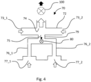
- the two secondary conduits 76_1, 76_2 are merged and coupled to a confluent portion 79 which is connected to the interfacing inlet 75 of the primary conduit 72. This arrangement is shown in Figure 4 .
- the secondary conduits may comprise a first secondary conduit 76_1 and a second secondary conduit 76_2.
- a confluent portion 79 having first and second ends is also provided.
- the first secondary conduit 76_1 comprises a respective first secondary inlet 77_1 in fluidic communication with the working space 4, and a respective first secondary outlet 78_1.
- the second secondary conduit 76_2 comprises a respective second secondary inlet 77_2 in fluidic communication with the working space 4, and a respective second secondary outlet 78_2.
- the first secondary outlet 78_1 and the second secondary outlet 78_2 are in fluidic communication with the first end of the confluent portion 79 and arranged so as to combine the flows from the first and second secondary outlets 78_1, 78_2 into the confluent portion 79.
- the interfacing inlet 75 of the primary conduit 72 is in fluidic communication with the second end of the confluent portion, so as to receive the combined flows from the confluent portion.
- the flow control device 80 in this example is again a fan, which may be located at a location within the secondary path as required.
- the flow control device 80 may be located at the merging location of the secondary conduits, or in the confluent portion 79. In other words, two or more secondary conduits may share the same flow control device.
- each secondary conduit may be controlled by further flow control devices, such as by flow restrictors that can restrict the cross sectional area of a portion of the flow path, positioned in each of the secondary conduits.
- flow control devices such as by flow restrictors that can restrict the cross sectional area of a portion of the flow path, positioned in each of the secondary conduits.
- some or all of the secondary conduits may each comprise an individually controllable flow restrictor, upstream of the shared fan, so as to adjust the flow resistance of each secondary conduit and thus alter the volume flow rate out of the respective secondary outlet.
- the further flow control device may be an adjustable flow restrictor for restricting the flow of gas from the secondary conduit into the primary conduit.
- the degree of flow restriction may thus be altered so that the flow through the two secondary conduits may be adjusted dynamically. This in turn will alter the flow profile through the working space 4.
- providing two secondary inlets 77_1, 77_2 in fluidic communication with the working space 4 may be advantageous where the working space 4 comprises at least two working space inlets, located such that each secondary inlet receives gas flow substantially from a respective working space inlet 66_1, 66_2,.
- FIGS 2A, 2B , 3A, 3B and 4 show gas extraction systems in which a fan actively provides flow through the secondary conduits 76_1, 76_2, an alternative arrangement of flow control devices within the gas extraction system 70 may be provided that achieves a similar effect.
- the sole source of extraction may be provided by the external extraction source 100. This will now be illustrated with reference to Figures 5, 6 , 7A and 7B .
- Example 2 Figures 5, 6, 7A and 7B with passive flow control devices (e.g. flow restrictors) using external extraction as the only suction system
- passive flow control devices e.g. flow restrictors
- the gas extraction system 70 shown in Figure 5 is an alternative to that shown in Figure 2A and in which the flow device 80 is a flow restrictor, with all parts of the system labelled with like numerals.
- Maximum flow through the secondary conduit 76 is achievable when the flow restrictor is at a setting where it least restricts the flow through the conduit, i.e. when the conduit presents the lowest possible resistance to gas flow.
- minimum or no flow is achieved when the flow restrictor is at a setting where it restricts most of, or completely blocks, the flow through the conduit 76, i.e. when the conduit 76 presents the highest achievable resistance to gas flow.
- the absolute flow values are governed by the volume flow rate into the primary outlet 74 as provided by the suction of the external extraction source 100.
- the primary inlet 73 is open to inflowing gas from an environment external to the working space 4. Similar design considerations apply with respect to the flow path resistance between the primary inlet 73 and the primary outlet 74, and between the secondary inlet 77 and the secondary outlet 78.
- the secondary outlet connects to the interfacing inlet (not labelled) of the primary conduit 72.
- the flow through the secondary conduit 76 may be controlled by adjusting the flow restrictor setting, so that either more or less gas is suctioned into the primary inlet 73 depending on the flow restrictor setting.
- At least one of the flow control device(s) 80 may be an adjustable flow restrictor capable of altering the flow resistance between the first primary inlet 73 and the primary outlet 74.
- the flow restrictor may alternatively, or additionally, be located at or near the working space gas inlet 66 to control the gas flow into the working space gas inlet.
- a flow restrictor may be located between the first primary inlet 73 and the first interfacing inlet 75, so as to control the inflow of gas into the primary conduit 72 via the primary inlet 73.
- An apparatus having a gas extraction system 70 with such a flow restrictor 80 positioned at or near the primary inlet 73 instead of in the secondary conduit 76 is shown in Figure 6 .
- the flow through the secondary conduit 76 may be controlled by adjusting the setting of the flow restrictor 80 at or near the primary inlet 73 (or in the example of Figure 6 , at any position between the primary inlet 73 and the primary outlet 74 and before the interfacing inlet that connects to the secondary outlet 78), so that either more or less gas is drawn into the primary inlet 73 depending on the restrictor setting.
- Figure 7A shows a variant of Figure 6 and is equivalent in conduit arrangement to that of Figure 3A , in which two secondary conduits 76_1, 76_2 and two primary inlets 73_1, 73_2 are provided.
- a flow restrictor 80_1P, 80_2P is provided at each primary inlet 73_1, 73_2 respectively. Again the position of each flow restrictor 80_1P, 80_2P is such that it is located at some location between the primary inlet 73_1, 73_2 and the closest interfacing inlet / secondary outlet 78_1, 78_2.
- the primary conduit 72 may thus comprise a second primary inlet 73_2 being at least partially open to the environment external to the working space.
- a further alternative arrangement of the gas extraction system 70 may be envisaged, combining the conduit arrangement of Figure 3A and the flow restrictor location of Figure 5 , such that in each secondary conduit 76_1, 76_2 a flow restrictor is present to individually control the flow through each secondary conduit, while the source of extraction is the external extraction source 100 connected to the primary outlet 74.
- the primary inlets 73_1, 73_2 may offer no impediment to inflowing gas.
- the primary conduit 72 may additionally comprise further flow restrictors to further adjust the inflow of gas into the primary inlets 73_1, 73_2.
- FIG. 7B An example of such an arrangement is shown in Figure 7B , where a first flow restrictor 80_1P is provided between the first primary inlet 73_1 and the first secondary outlet 78_1, and a second flow restrictor 80_2P is provided between the second primary inlet 73_2 and the second secondary outlet 78_2.
- the secondary conduits 76_1 and 76_2 each comprise a flow restrictor 80_1 S and 80_2S. This arrangement may provide a larger more flexible and individually adjustable range of flow rate control.
- the two or more secondary paths 76_1, 76_2 may be merged via a confluent portion 79 (equivalent to that of Figure 4 ) before connecting to the primary conduit 72.
- the confluent portion 79 may comprise an adjustable flow restrictor to control all secondary conduit flows, where the individual secondary conduit restrictors are optional, depending on whether individual control per secondary conduit is required.
- the apparatus 1 may comprise a controller 90 configured to connect to and control the one or more flow control devices.
- the controller 90 is generally configured to carry out a method of gas extraction from the working space 4 of the apparatus 1 utilising the gas extraction system 70 as described herein, the method comprising the steps of: (a) extracting gas from the working space 4 via the secondary conduit 76 comprising a respective secondary inlet 77 and a secondary outlet 78, the secondary inlet 77 receiving gas from the working space 4; while (b) moving the gas from the secondary conduit 76 via the secondary outlet 78 to the primary conduit 72 via the first interfacing inlet 75 of the primary conduit; while (c) extracting the gas from a primary outlet 74 of the primary conduit 72 by operating the external extraction source 100 connected to the primary outlet 74; and while (d) suctioning, by operating the external extraction source, a flow of gas from an environment external to the working space into the primary conduit 72 via a primary inlet 73 of the primary conduit that is open to the environment external to the working space 4, such that the gas extracted in step (c) is a mixture of gas extracted from the working space 4 via the first interfacing in
- Steps (a) and (b) may be carried out by operating an internal flow control device 80 located in the secondary conduit 76 to control the flow of gas through the secondary conduit.
- the internal flow control device is a fan; further variants equally apply as described in relation to the apparatus herein.
- the method may further comprise the steps of: detecting a property of the gas flow at the primary inlet 73; determining that the detected property is outside a normal operating range for a predetermined duration; and generating a failure signal.
- the sensor 92 may be a temperature sensor such as a thermistor, where the property detected is temperature.
- a further sensor in the form of a flow meter may be located at the primary inlet 73 and/or outlet 74 of the primary conduit 72, the primary outlet 74 being connected to the external source of extraction 100; and the method may further comprise: detecting a property of the gas flow at the primary inlet and/or the primary outlet; determining that the detected property is outside a normal operating range for a predetermined duration; and generating a failure signal.
- the failure signal may terminate a build operation of the apparatus.
- the gas extraction system 70 may further comprise a second secondary conduit 76_2 and a second internal flow control device 80_2 located in the second secondary conduit (as illustrated for example in Figure 8A ), and wherein in parallel to steps (a), (b) and (d) further steps of the method comprise: (a1) extracting gas from the working space 4 via the second secondary conduit 76_2 comprising a respective second secondary inlet 77_2 and a second secondary outlet 78_2, the second secondary inlet 77_2 receiving gas from the working space 4; while (b1) operating the second internal flow control device 80_2 to control the flow of gas from the second secondary conduit 76_2 via the second secondary outlet 78_2 to the primary conduit 72 via a second interfacing inlet 75_2 of the primary conduit 72; and while (d1) suctioning, by operating the external extraction source 100, a flow of gas from an environment external to the working space into the primary conduit 72 via a second primary inlet 73_2 of the primary conduit 72 that is open to the
- the described methods and variants that may be envisaged based on the apparatus described herein provide a controllable and adjustable flow of gas out of the working space 4 of the apparatus 1 even when the apparatus is connected, via the gas extraction system, to the high suction of the site ventilation system.
- the working space inlet 66 may be open to an environment external to the working space, for example the inlet may be one or more holes that connect the working space 4 to the ambient environment, and the internal flow control device(s) provide the necessary suction to draw gas into the working space via the working space inlet(s) 66.
- a controller is provided and configured to control the at least one internal flow control device 80, and/or to receive measured values from the one or more sensors 92.
- the controller 90 may thus be configured to connect to one or more sensors of the apparatus 1.
- the sensors may be one or more of a temperature sensor, flow meter or pressure sensor or any other suitable sensor for monitoring flow and/or temperature of the apparatus, and may be located at any suitable location within one or more of the primary conduit 72, including one or more of the primary inlet(s) 73, primary outlet 74, interfacing inlet(s) 75; the secondary conduit(s) 76, including one or more of the secondary inlet(s) 77, secondary outlet(s) 78, or the confluent portion 79; and the working space 4; so as to provide a measurement of one or more of temperature, volume flow rate or gas pressure to allow an improved control of the working space temperature within the apparatus 1.
- the controller 90 may have one or more of several functions. For example, to control the temperature of the working space 4, the flow rate through the secondary conduits 76 may be adjusted to remove more or less of the hot gas from the working space 4. For example, a target value of temperature may be defined for the working space 4, measured at one or more locations within the working space 4, or within the one or more secondary conduits 76 for example.
- the controller 90 may be configured to receive the target values and measured values and determine a deviation between the two, and then determine a suitable control signal that is provided by the controller to the flow control devices of the gas extraction system 70 so as to modify the rate of extraction and thus move closer to or achieve the target temperature.
- the control signal may for example be an adjusted power setting for the flow control device 80, in the case of a fan, or an adjusted position setting, in the case of a flow restrictor.
- These adjusted settings may be provided in the form of a lookup table that defines which setting is suitable for a determined deviation so as to achieve the target value.
- the fans may continue to operate and draw hot gas from the working space 4 into the primary conduit 72 via the secondary conduit(s) 76.
- the primary outlet 74 In the absence of extraction, or too low flow rates, through the primary outlet 74, this will lead to hot gases from the working space 4 backflowing through the primary inlets 73, i.e. flowing in a direction opposite to the intended direction so that hot gas (and any fumes/particulates contained therein) is released to the external environment outside the working space 4. This is undesirable.
- the fans in the secondary conduits 76 may be turned off by the controller 90 in response to one or more of the following:
- one or more temperature sensors may be located at or near the primary inlet(s) 73.
- the controller 90 is configured to receive a maximum value for temperature that is acceptable to represent a normal operating range at or near the primary inlet(s) and above which a low flow or failure of the external extraction source 100 is indicated.
- the controller further receives one or more measured values of temperature from the one or more temperature sensors, and determines whether a measured value exceeds the maximum acceptable value. If the maximum acceptable value is exceeded, the controller provides an alert such as a failure signal to the user.
- one or more flow meters may be located at or near the primary inlet(s) 73, or at the primary outlet 74.
- the flow meters are configured to detect a gas flow rate.
- the controller is configured to receive (for example from user input) or store a minimum value for flow rate that is acceptable to represent a normal operating range at or near the primary inlet(s) 73, or at the primary outlet 74, below which a low flow or failure of the external extraction source 100 is indicated.
- the controller 90 further receives one or more measured values of gas flow rate from the one or more flow meters, and determines whether a measured value falls below the minimum acceptable value. If the value is lower than the minimum acceptable value, the controller provides an alert, such as a failure signal to the user.
- one or more flow meters may be located at or near the primary inlet(s) 73.
- the flow meters are configured to detect a flow direction.
- the controller is configured to receive a setting indicating backflow through the primary conduit 72, where backflow is opposite to the flow during normal operation, and where normal flow is flow from the primary inlet(s) 73 into the primary conduit 72.
- the controller is further configured to receive a setting value from the one or more flow meters, and determines whether a received setting value indicates low flow or failure of the external extraction source 100. If the controller determines backflow through one or more of the flow meters, which in turn signals low flow or failure of the external extraction source 100, the controller provides an alert, such as a failure signal, to the user.
- the controller 90 may further receive a predetermined duration over which the measured value may be outside of the normal operating range. If the controller determines that the predetermined duration has been exceeded, over which the measured value has continuously been outside of the normal operating range, or outside normal operation, the alert is issued.
- the alert may comprise a failure signal to cause termination of a build operation, whereby the controller 90 shuts down certain process components - for example, switching off one or more of the heat sources of the apparatus, switching off motion of the carriages, and thus terminating the build process of the object.
- controller 90 for controlling the apparatus comprising the above described gas extraction system 70, configured to do at least one of the following:
- controller 90 may be configured to adjust, based on receiving data from the sensor 92, the flow rate of gas through the one or more secondary conduits 76 to as to control the temperature in the working space 4, and/or to determine whether the apparatus 1 is outside normal operating conditions and issue a failure signal, for example where the external source of extraction 100 has failed and hot gas is exiting through the primary inlet(s) 73 into the environment exterior to the working space.
- the controller 90 is configured to receive a predetermined duration over which the measured temperature at the primary inlet(s) 73 may fall outside of a normal operating range, and once the respective predetermined duration has been exceeded, issue the failure signal.
- the control signal may comprise an adjusted setting for the one or more of the flow control devices 80.
- the adjusted setting may correspond to a desired value or target value for a determined difference between the measured value and the target value and may be provided to the controller 90 in form of a look-up table.
- the target value is a temperature
- the adjusted setting indirectly changes the measured value (i.e. temperature) by adjusting the flow rate, for example.
- the control signal may be an adjusted flow rate setting that is provided to the one or more fan(s) or flow restrictor(s) within the gas extraction system 70 in order to achieve the temperature target of a measured temperature, as measured, for example, by a sensor 92 located in the working space 4.
- control signal may be provided to the one or more fan(s) or flow restrictor(s) within the gas extraction system 70 in order to achieve the flow rate target.
- the adjusted setting directly changes the measured value.
- the adjusted setting is chosen so as to achieve the target value of one of temperature, flow rate or pressure.
- a particle filter may be fitted within the primary conduit 72, at a location between the secondary outlet 78 and the or each primary inlet 73 (for example a first filter at a location between secondary outlet 78_1 and primary inlet 73_1, and a second filter at a location between secondary outlet 78_2 and primary inlet 73_2).
- particle filters may be fitted in the secondary conduits. This may be beneficial in case of backflow and where the gas of the working space 4 comprises polluting particles or fumes.
- a particle filter will contribute to the flow resistance of the or each primary inlet 73 (or generally of the flow path it is located in), which will have to be taken into consideration when designing the gas extract system 70.
- the filter may be a scrubber for gas fumes. If a particle filter is present, a warning signal to indicate extract failure may be sufficient.
- the failure signal may be generated in response to a temperature sensor or flow meter located at or near the primary inlet(s) 73 providing a temperature measurement or a flow meter value or setting to the controller 90 that exceeds a predefined threshold temperature, or falls below a predefined threshold flow rate.
- the predefined threshold temperature may for example be a temperature in the range of 40-60 °C, for example 50 °C.
- a flow meter at or near the primary inlet(s) may indicate backflow as a result of detecting flow from the primary conduit out of the primary inlets, which is a reversal of flow direction that is opposite to the flow direction under normal operating conditions (i.e. from the primary inlet(s) into the primary conduit).
- the failure signal may alternatively be generated in response to a flow meter measurement provided to the controller 90 by a flow meter located in the primary conduit outlet 74 that signals low flow or no flow into the primary conduit 72.
- the controller may also be configured to receive a predefined margin value for one or more of a temperature, flow or pressure target or threshold.
- the predefined margin defines a margin within which the target or threshold remains fulfilled, and an action is not triggered by the controller such as to provide an adjusted control signal or to issue a failure signal.
- the predefined margin may be defined by the user, or it may be dependent on the measurement accuracy of the sensor.
- the failure signal may comprise a control signal for controlling process components within the working space 4 of the apparatus 1; for example, the failure signal may comprise a control signal that turns off power to the fans.
- the process components may comprise one or more carriages 30, one or more infrared lamps, and an overhead heater 20 located above the build bed surface 12, wherein the one or more infrared lamps are supported by one or more of the carriages 30, and wherein the carriages 30 are movable across the powder build bed surface 12, driven by carriage motion devices.
- the power control signal may be configured to turn off power to one or more of the infrared lamps; the overhead heater 20; and the carriage motion devices, so as to stop the carriages 30 from moving across the build bed surface 12.
- adjustable flow restrictors may be located in the gas extraction system 70 to improve the safety of the apparatus 1 in the event of failure or low extraction rate of the external extraction source 100.
- one or more flow restrictors arranged to shut off the primary inlets 73 may be located at or near the primary inlet(s) 73.
- one or more flow restrictors arranged to shut off flow between the primary conduit 72 and the working space 4 may be located within the secondary conduit(s) 76, or at the secondary inlet(s) 77 or at the secondary outlet(s) 78.
- the failure signal may thus further, or instead, comprise a shut off control signal to the one or more flow adjusting devices located at or near the one or more of the primary inlet(s) 73, at or near the one or more secondary inlet(s) 77, at or near the outlet(s) 74, 78, or at or near the working space inlet(s) 66, such that the one or more flow adjusting devices move to a shut position to block the flow of gas so as to prevent the gas from backflowing through the primary inlet(s) 73 to the environment external to the working space 4.
- a shut off device may be located upstream of the flow control device within the secondary conduit 76, for example near or at the secondary conduit inlet 77, that can cause the secondary conduit 76 to be blocked to gas flow. This will prevent the external extraction source 100 from extracting gas past the fan and out of the working space 4, leaving the working space 4 undisturbed.
- the controller may thus be configured to control a shut off means located downstream of the flow control in the secondary conduit 76, so as to provide a shut off signal to the shut off means that causes the secondary conduit 76 to be blocked to gas flow.
- the shut off signal may be synchronized with a power control signal provided to the flow control device 80, where the flow control device is a fan, that causes the fan to stop extracting gas from the working space 4.
- the shut off means may be a baffle or a butterfly valve.
- adjustable flow restrictors in the secondary conduit(s) 76 as shown in Figures 5 and 7 may be beneficial since they may act both as a flow control device and a shut off / safety valve.
- passive control devices such as flow restrictors as dynamic flow control devices in the secondary conduit(s) 76 may be beneficial since a failure of the external source of extraction 100 will not lead to hot gases from the working space 4 being extracted, as would be the case where an active device such as a fan is used.
- FIG. 9 an apparatus 1 is illustrated that comprises the gas extraction system 70 according to the present disclosure, using the variant of Figure 3A .
- Figures 8A-8C and 9 examples of the gas extraction system 70 and the apparatus using sensors as failure indicators
- FIGs 8A-8C schematically show details of an implementation of the gas extraction system 70 having two secondary conduits 76_1, 76_2, each having a respective elongate secondary inlet 77_1, 77_2.
- Each secondary conduit 76_1, 76_2 comprises a respective fan 80_1, 80_2, similar to the system in Figure 3A .
- the primary inlets 73_1, 73_2 in this example are open and comprise temperature sensors 92_1, 92_2 connected to a controller 90.
- the fans 80_1, 80_2 are also connected to the controller 90, as indicated by the dashed lines.
- the elongate secondary inlets 77_1, 77_2 may be arranged to span the width of the build bed surface 12 below when the system 70 is fitted to the apparatus 1.
- Flow conditions into the secondary inlets 77_1, 77_2 may be improved by providing the inlet with a tapered shape such as the one shown in Figure 8B or 8C , where the fan 80_1 (or 80_2) is located either directly above a symmetrical tapered inlet ( Figure 8B ) or off to one side of a wedge-shaped inlet ( Figure 8C ).
- Providing a uniform inflow of gas into the secondary inlets 77_1, 77_2 may be beneficial where certain flow conditions are to be set up along either side of the build bed surface 12.
- the controller 90 may be connected to and controlling the fans 80_1 and 80_2 so as to adjust the gas flow rate through the secondary conduits 76_1, 76_2 in response to temperature measurements made by the temperature sensors 92_1, 92_2.
- Figure 9 shows the gas extraction system 70 of Figure 8 comprised within the apparatus 1.
- the apparatus has a working space 4 bounded by the working surface 13 comprising the build bed surface 12, side walls including two opposing side walls 62, and a ceiling 60.
- Two opposing side walls 62 facing along the direction of travel of carriage 30 each comprise a respective working space inlet 66_1, 66_2.
- the secondary inlets 77_1 and 77_2 are arranged above and to either side of the build bed surface 12, spanning the width of the build bed surface 12, in this case orthogonal to the direction of travel of the carriage 30.
- the elongation of the secondary inlets 77_1, 77_2 and the position of the working space inlets 66_1, 66_2 may be arranged such that a gas curtain is set up to either side of the build bed surface 12 that allows an improved temperature control of the build bed surface 12.
- the design of the secondary inlets 77_1, 77_2, for example by providing tapers (e.g. as shown in Figures 8B and 8C ) that enhance gas flow uniformity into the inlet along the direction of elongation, may provide additional benefits in uniformity of temperature control.
- a controller 90 is connected to process components of the working space 4, such as to the motion control device (not shown) for carriage 30, and infrared lamps supported on the carriage, and to the overhead heater 20 located above the build bed surface 12.
- the primary inlets are shown to be provided with sensors 92_1 and 92_2 to monitor one or more of temperature, flow rate, pressure and flow direction at or near the primary inlets 73_1, 73_2. This illustrates a position of sensors that may be used to indicate a failure of or low flow at the external source of extraction 100.
- the controller 90 may be arranged to monitor and analyse measurements provided by the sensors 92_1, 92_2 and compare to them to values indicating normal operation. If the values deviate from those measured, the controller 90 may issue a failure signal. For example, if the external source of extraction 100 provides low or no flow, and the fans in the secondary conduits 76_1, 76_2 are still operating, a temperature value that is higher than a temperature indicating normal operation may be detected by at least one of the sensors 92_1, 92_2 at the primary inlets 73_1, 73_2.
- the measured values may deviate from the predetermined threshold value by a predefined margin.
- This margin may be a user defined percentage, or a be associated with the accuracy of the sensor measurement.
- the controller may further monitor a duration over which the measured value is continuously such that it represents an abnormal operation. Only once the monitored duration exceeds a predetermined duration, the controller issues a failure signal to alert the user to abnormal operation, and optionally to terminate a build operation (such termination being controlled by the controller).
- a controllable and adjustable flow of gas out of the working space 4 of the apparatus 1 may be achieved even when the apparatus is connected, via the gas extraction system, to the high suction of the site ventilation system.
- the working space 4 of the apparatus 1 may comprise one or more working space gas inlets 66, arranged in one of the bounding surfaces, that is/are dedicated to help define the gas flow profile through the working space 4 in cooperation with the secondary inlet(s) 77.
- the flow extracted by the external extraction source 100 equals the combined flow into the primary conduit 72 from the one or more primary inlets 73 and from the one or more secondary outlets 78
- the one or more flow control devices may generate an underpressure within the working space 4 of the apparatus 1 compared to the pressure outside of the working space 4.
- the pressure external to the working space 4 may be ambient pressure.
- the combined primary flow resistance between the primary inlets 73 and their respective closest interfacing portion may be lower than the combined flow resistance between the secondary inlets 77 and their respective secondary outlets 78.
- the flow resistance of the combined primary inlets to the primary outlet is lower than the flow resistance of the combined secondary inlets to the respective secondary outlets.
- the secondary inlets 77 may be located in the ceiling; for example first and second secondary inlets 77_1, 77_2 may each be facing an area at or near opposite ends of the build bed surface 12.
- Any of the gas extraction system 70 or the apparatus 1 may have one or more sensors.
- a sensor may for example be located at one or more of the primary outlet 74, a primary inlet 73, a secondary inlet 77, a secondary conduit 76, and within the working space 4.
- the sensor may be a temperature sensor, flow meter or pressure sensor. Different sensor types maybe present at different locations.
- a particle filter may be fitted within the primary conduit, at a location between the secondary outlet 78 and the primary inlet 73 (for example a first filter at a location between secondary outlet 78_1 and primary inlet 73_1, and a second filter at a location between secondary outlet 78_2 and primary inlet 73_2 in Figure 8 ). This may be beneficial in case of backflow and where the gas of the working space 4 comprises polluting particles or fumes.
- the particle filter will contribute to the flow resistance of the primary inlet(s) 73, which will have to be taken into consideration when designing the gas extract system 70.
- This the apparatus may comprise a filter at or near the one or more primary inlets 73, or between the secondary inlet 77and the respective primary inlet 73 to filter impurities from the gas extracted from the working space 4 in case of reversal of flow such that gas flows from the one or more secondary inlets 77 to the respective primary inlet 73.
- the apparatus may further, or instead, comprise a controller 90 for controlling the one or more flow control devices 80 in response to one or more measurements of:
- Primary inlet is "open/unimpeded to inflowing gas flow" or “partially open / partially impeded”:
- An adjustable flow restrictor or a shut off valve may be located within the primary conduit 72 and/or at the primary inlet(s) 73. Examples of arrangements are shown in Figures 5 to 7B .
- the primary inlet(s) 73 are either fully open such that, for example, the flow resistance between primary inlet 73 and primary outlet 74 is lower compared to the flow resistance between the secondary inlet 77 and secondary outlet 78.
- an adjustable flow restrictor may be present at a suitable location in the primary conduit 72, between the primary inlet 73 and the secondary outlet 74/interfacing inlet 75 (or the primary outlet 74, if this located closer to the primary inlet 73 than the secondary outlet 78).
- the flow restrictor would allow gas to enter the primary inlet 73 at any time.
- the primary inlet 73 is 'partially open' or 'partially unimpeded to inflowing gas'.
- the adjustable restrictor 80_P shut off the primary inlet 73; this is to be treated as a special case to do with control of the gas extraction system 70 or the apparatus using the gas extraction system 70 in the case of non-normal operation.
- the above variants describe the gas extraction system 70 and its operation with reference to the apparatus 1.
- the gas extraction system 70 may be provided as an integral part of the apparatus 1.
- the gas extraction system 70 may be provided as a separate part, for use in the apparatus 1.
- the gas extraction system 70 provided as a separate part may have the features, options and combinations of those of the gas extraction systems 70 disclosed above.
- a gas extraction system 70 for use in an apparatus 1 for the layer-by-layer formation of three-dimensional objects having an enclosed working space 4 from which gas is to be extracted, wherein the gas extraction system 70 comprises:
- the gas extraction system 70 upon connection to an external extraction source 100, may be arranged such that the flow extracted by the external extraction source 100 equals the combined flow into the primary conduit 72 from the primary inlet(s) 73 and from the secondary outlet(s) 78.
- the secondary conduit(s) 76 may comprise the first secondary conduit 76_1 and a second secondary conduit 76_2, the primary conduit may further comprise a second interfacing inlet, and the second secondary conduit 76_2 may comprise a respective second secondary inlet 77_2 for fluidic communication with the working space 4, and a respective second secondary outlet 78_2 in fluidic communication with the second interfacing inlet 75_2.
- the secondary conduit(s) 76 may comprise the first secondary conduit 76_1 and a second secondary conduit 76_2, the second secondary conduit 76_2 comprising a respective second secondary inlet 77_2 for fluidic communication with the working space 4, and a respective second secondary outlet 78_2; and a confluent portion 79 may be provided having first and second ends, wherein the first secondary outlet 78_1 and the second secondary outlet 78_2 are in fluidic communication with the first end of the confluent portion 79 and arranged so as to combine the flows from the first and second secondary outlets 78_1, 78_2 into the confluent portion, and wherein the first interfacing inlet 75 is in fluidic communication with the second end of the confluent portion, so as to receive the combined flows from the confluent portion.
- At least one of the flow control devices may be located in the confluent portion.
- at least one of the flow control device(s) 80 may be located in at least one of the secondary conduits 76.
- the flow control devices 80 may be positioned at suitable locations within the gas extraction system 70.
- one of the flow control devices 80 may be located in the first secondary conduit 76_1, and another of the flow control devices 80 may be located in the second secondary conduit 76_2.
- at least one of the flow control device(s) 80 may be an adjustable flow restrictor capable of altering the flow resistance between the first primary inlet 73 and the primary outlet 74.
- at least one of the flow control device(s) 80 may be a fan for moving gas from a secondary inlet 77 to a respective secondary outlet 78.
- At least a further flow control device 80 may be provided in the form of an adjustable flow restrictor for restricting the flow of gas from a secondary conduit 76 into the primary conduit 72.
- the primary conduit 72 may have one or more primary inlets 73, and at least one of the inlets may be unimpeded to inflowing gas flow.
- one or more of the primary inlets 73 may be at least partially unimpeded to inflowing gas flow and be at least partially open to the environment external to the primary conduit 72.
- one or more of the primary inlet(s) 73 may comprise an adjustable flow restrictor that may be used to control the inflowing gas into the primary inlet 73, or it may be used to shut off the primary inlet 73 in case of failure of the external source of extraction 100.
- The, or a further, flow control device may be located between the first primary inlet 73 and the first interfacing inlet 75.
- the flow control device 80 may be an adjustable flow restrictor.
- the adjustable flow restrictor may, for example, be located at or near the first primary inlet 73, operable to restrict or shut off inflowing gas flow.
- the flow resistance of the combined primary inlet(s) 73_1, 73_2 to the primary outlet 74 may be lower than the flow resistance of the combined secondary inlet(s) 77_1, 77_2 to the respective secondary outlet(s) 78_1, 78_2.
- the first and second secondary inlets 77_1, 77_2 may be arranged to be connected to respective openings in the ceiling of the working space 4.
- the various implementations of the gas extraction system 70 may comprise a sensor at one or more location(s), such as at or near the primary outlet 74, at or near the primary inlet(s) 73, at or near the secondary inlet(s) 77, within the secondary conduit(s) 76.
- the sensor may be a temperature sensor, flow meter or pressure sensor. Different types of sensors may be present in the gas extraction system 70 at one or more locations.
- a particle filter may be located at or near the one or more primary inlet(s) 73, or at a suitable location between a secondary inlet 77 and the respective primary inlet 73, to filter impurities from the gas extracted from the working space 4.
- the gas extraction system 70 may be adapted to flow gas extracted from the working space past the back of the overhead heater 20.
- the primary conduit may be arranged to as to be in thermal contact with the back of the overhead heater 20 since gas entering the primary inlet(s) 73 is cooler than the gas extracted from the working space. In this way, the gas suctioned by into the primary outlet by the external source of extraction may be used to carry away heat from the back of the overhead heater 20.
Landscapes
- Engineering & Computer Science (AREA)
- Chemical & Material Sciences (AREA)
- Materials Engineering (AREA)
- Manufacturing & Machinery (AREA)
- Physics & Mathematics (AREA)
- Optics & Photonics (AREA)
- Mechanical Engineering (AREA)
- Health & Medical Sciences (AREA)
- Environmental & Geological Engineering (AREA)
- Toxicology (AREA)
- Structures Of Non-Positive Displacement Pumps (AREA)
Claims (15)
- Vorrichtung (1) zur schichtweisen Herstellung von dreidimensionalen Objekten (2), wobei die Vorrichtung ein Gasextraktionssystem (70) und einen geschlossenen Arbeitsraum (4) umfasst, aus dem Gas extrahiert werden soll,wobei der Arbeitsraum (4) von Seitenwänden (62), einer Decke (60) und einer Arbeitsfläche (13) umschlossen ist und einen Arbeitsraumeinlass (66), um Gas in den Arbeitsraum (4) eintreten zu lassen, und einen Arbeitsraumauslass, um Gas aus dem Arbeitsraum (4) austreten zu lassen, umfasst, wobei die Arbeitsfläche (13) eine Baubettoberfläche (12) umfasst, in der eine Schicht des Objekts (2) gebildet wird;wobei das Gasextraktionssystem (70) umfasst:eine Primärleitung (72) mit einem ersten Primäreinlass (73), der zu einer Umgebung außerhalb des Arbeitsraums (4) offen ist, einem ersten Verbindungseinlass (75_1) und einem Primärauslass (74), der mit einer externen Extraktionsquelle (100) verbunden werden kann, um Gas aus der Primärleitung (72) abzusaugen;eine erste Sekundärleitung (76_1), die einen ersten Sekundäreinlass (77_1) in Fluidverbindung mit dem Arbeitsraum (4) zur Extraktion von Gas aus dem Arbeitsraum (4) und einen ersten Sekundärauslass (78_1) umfasst; undeine zweite Sekundärleitung (76_2) mit einem zweiten Sekundäreinlass (77_2) in Fluidverbindung mit dem Arbeitsraum (4) zur Extraktion von Gas aus dem Arbeitsraum (4) und einem zweiten Sekundärauslass (78_2);wobei die ersten und zweiten Sekundäreinlässe (77_1, 77_2) in der Decke (60) angeordnet sind, und jeweils einem Bereich an oder in der Nähe von gegenüberliegenden Enden der Baubettoberfläche (12) zugewandt sind;wobei:(a) die Primärleitung (72) ferner einen zweiten Verbindungseinlass (75_2) umfasst, wobei der erste und der zweite Sekundärauslass (78_1, 78_2) in Fluidverbindung mit dem jeweiligen ersten und zweiten Verbindungseinlass (75_1, 75_2) stehen, oder(b) das Gasextraktionssystem (70) ferner einen konfluenten Abschnitt (79) mit einem ersten und einem zweiten Ende umfasst, wobei der erste Sekundärauslass (78_1) und der zweite Sekundärauslass (78_2) in Fluidverbindung mit dem ersten Ende des konfluenten Abschnitts (79) stehen und so angeordnet sind, dass sie die Ströme von dem ersten und dem zweiten Sekundärauslass (78_1, 78_2) in den konfluenten Abschnitt (79) kombinieren, und wobei der erste Verbindungseinlass (75_1) in Fluidverbindung mit dem zweiten Ende des konfluenten Abschnitts (79) steht, um die kombinierten Ströme von dem konfluenten Abschnitt (79) aufzunehmen;und wobei das Gasextraktionssystem (70) ferner eine oder mehrere Strömungssteuerungsvorrichtungen (80) zur Steuerung der Gasströmung aus dem Arbeitsraum (4) in die ersten und zweiten Sekundärleitungen (76_1, 76_2) und aus den ersten und zweiten Sekundärleitungen (76_1, 76_2) in den Primärauslass (74) der Primärleitung (72) umfasst.
- Die Vorrichtung nach Anspruch 1 mit der Option (b), bei der mindestens eine der Strömungssteuerungsvorrichtung (en) (80) in dem konfluenten Teil angeordnet ist.
- Die Vorrichtung nach Anspruch 1, wobei eine erste Strömungssteuerungsvorrichtung (80_1) der einen oder mehreren Strömungssteuerungsvorrichtungen (80) in der ersten Sekundärleitung (76_1) angeordnet ist und eine zweite Strömungssteuerungsvorrichtung (80_2) der einen oder mehreren Strömungssteuerungsvorrichtungen (80) in der zweiten Sekundärleitung (76_2) angeordnet ist.
- Die Vorrichtung nach einem der vorhergehenden Ansprüche, wobei mindestens eine der Strömungssteuerungsvorrichtung(en) (80)ein einstellbarer Strömungsbegrenzer, mit dem der Strömungswiderstand zwischen dem ersten Primäreinlass (73) und dem Primärauslass (74) verändert werden kann, und/oderein Gebläse zum Bewegen von Gas aus dem Arbeitsraum (4) in den ersten und/oder zweiten Sekundäreinlass (77_1, 77_2) und durch die erste und/oder zweite Sekundärleitung (76_1, 76_2) zu dem jeweiligen Sekundärauslass (78_1, 78_2)ist.
- Die Vorrichtung nach einem der vorhergehenden Ansprüche, wobei die Primärleitung (72) ferner einen zweiten Primäreinlass (73_2) umfasst, der zumindest teilweise zur Umgebung außerhalb des Arbeitsraums (4) offen ist.
- Die Vorrichtung nach einem der vorhergehenden Ansprüche, wobei der Strömungswiderstand des kombinierten Strömungsweges von dem/den Primäreinlass/-einlässenen (73) zu dem Primärauslass (74) geringer ist als der Strömungswiderstand des kombinierten Strömungswegs von dem/den Sekundäreinlass/-einlässen zu dem/den jeweiligen Sekundärauslass/- auslässen.
- Die Vorrichtung nach einem der vorhergehenden Ansprüche ferner umfassend einen Sensor (92) an einem oder mehreren von dem Primärauslass (74), dem/den Primäreinlass/-einlässen (73_1, 73_2), dem/den Sekundäreinlass/-einlässen (77_1, 77_2), der/den Sekundärleitung(en) (76_1, 76_2) und innerhalb des Arbeitsraums (4); wobei der Sensor (92) einer oder mehrere von einem Temperatursensor, Durchflussmesser oder Drucksensor ist.
- Die Vorrichtung nach Anspruch 7, wobei der Sensor (92) ein Temperatursensor ist.
- Die Vorrichtung nach Anspruch 7 oder 8, ferner umfassend eine Steuerung (90), die dazu konfiguriert ist:
die mindestens eine interne Strömungssteuerungsvorrichtung (80) zu steuern; Messwerte von dem einen oder den mehreren Sensoren (92) zu empfangen; und eines oder mehrere von:(a1) einen Zielwert für eine oder mehrere der Größen Strömungsrate, Druck und/oder Temperatur sowie optional eine vorgegebene Dauer für jeden Zielwert zu erhalten;(b1) von dem einen oder den mehreren Sensoren (92) der Vorrichtung einen oder mehrere entsprechende gemessene Strömungsraten-, Druck- und/oder Temperaturwerte zu empfangen, die an einer oder mehreren Stellen im Arbeitsraum (4) und/oder in der (den) Sekundärleitung(en) (76_1, 76_2) gemessen werden;(c1) festzustellen, ob der gemessene Wert von dem entsprechenden Zielwert abweicht; und(d1) wenn der Messwert über die jeweils vorgegebene Dauer vom Sollwert abweicht,i. auf der Grundlage des Zielwerts ein entsprechendes Steuersignal für mindestens eine der Strömungssteuerungsvorrichtungen (80) zu bestimmen, undii. das Steuersignal an die mindestens eine Strömungssteuerungsvorrichtung (80) zu liefern. - Die Vorrichtung nach Anspruch 7 oder Anspruch 8, wobei der Sensor (92) einer oder mehrere von einem Temperatursensor, einem Durchflussmesser am oder in der Nähe des/der Primäreinlasses/-einlässe (73) und einem Ströumgsmesser am oder in der Nähe des Primärauslassses (74) ist, und die Vorrichtung ferner eine Steuerung (90) umfasst, die dazu konfiguriert ist:die mindestens eine interne Strömungssteuerungsvorrichtung (80) zu steuern; Messwerte von dem einen oder den mehreren Sensoren (92) zu empfangen; und(a2) einen Temperatur-Schwellenwert und/oder einen Strömungsmengen-Schwellenwert und/oder eine Einstellung des Strömungsrichtungsanzeigers für den Strömungsmesser sowie optional eine vorgegebene Dauer für jeden Schwellenwert oder jede Einstellung des Strömungsrichtungsanzeigers zu empfangen;(b2) von dem einen oder den mehreren Sensoren (92) einen oder mehrere Messwerte für Strömungsmenge, Temperatur und Strömungsrichtung zu empfangen;(c2) festzustellen, dass während einer Zeit, die länger als die jeweilige vorbestimmte Dauer ist, einer oder mehrere der gemessenen Temperaturwerte über dem Temperaturschwellenwert liegen und/oder dass die gemessene Strömungsrate unter einer Strömungsschwelle liegt und/oder dass die Einstellung der gemessenen Strömungsrichtung einem Rückfluss entspricht; und(d2) ein Fehlersignal zu geben, um eine Abweichung vom Normalbetrieb des Geräts anzuzeigen.
- Die Vorrichtung nach Anspruch 9 oder Anspruch 10, wobei das Steuersignal einen eingestellten Strömungswert umfasst, wobei der eingestellte Ströumngswert so gewählt wird, dass der Zielwert einer der Größen Temperatur, Strömungsmenge oder Strömungsdruck erreicht wird.
- Die Vorrichtung nach Anspruch 10 oder Anspruch 11, wobei das Fehlersignal ein Steuersignal zur Steuerung von Prozesskomponenten innerhalb des Arbeitsraums (4) der Vorrichtung umfasst, wobei die Prozesskomponenten einen oder mehrere Schlitten (30), eine oder mehrere Infrarotlampen und eine Deckenheizung (20), die oberhalb der Baubettoberfläche (12) angeordnet ist, umfassen, wobei die eine oder die mehreren Infrarotlampen von dem einen oder den mehreren Schlitten (30) getragen werden, wobei die Schlitten (30) durch eine Schlittenbewegungsvorrichtung über die Baubettoberfläche (12) bewegbar sind, und wobei das Leistungssteuersignal so konfiguriert ist, dass es die Leistung für einen oder mehrere voni. der einen oder den mehreren Infrarotlampen;ii. dem Deckenheizgerät (20); undiii. der einen oder den mehreren Schlittenbewegungsvorrichtungen.abschaltet.
- Das Verfahren zum Extrahieren von Gas aus dem Arbeitsraum (4) einer Vorrichtung zur schichtweisen Herstellung von dreidimensionalen Objekten (2) nach einem der Ansprüche 1 bis 12, umfassend die Option (a), wobei das Gasextraktionssystem (70) dazu konfiguriert ist:(a) Gas aus dem Arbeitsraum (4) über die erste und zweite Sekundärleitung (76_1, 76_2), die jeweils einen ersten und zweiten Sekundäreinlass (77_1, 77_2) und einen ersten und zweiten Sekundärauslass (78_1, 78_2) umfassen, zu extrahieren, wobei der erste und zweite Sekundäreinlass (77_1, 77_2) Gas aus dem Arbeitsraum (4) aufnehmen; während(b) Gas von den ersten und zweiten Sekundärleitungen (76_1, 76_2) über die jeweiligen ersten und zweiten Sekundärauslässe (78_1, 78_2) und die ersten und zweiten Verbindungseinlässe (75_1, 75_2) zu der Primärleitung (72) bewegt wird; während(c) das Gas aus dem Primärauslass (74) der Primärleitung (72) durch Betätigen der externen Extraktionsquelle (100), die mit dem Primärauslass (74) verbunden ist, extrahiert wird; und während(d) ein Gasstrom aus einer Umgebung außerhalb des Arbeitsraums (4) in die Primärleitung (72) über einen ersten Primäreinlass (73_1) und einen zweiten Primäreinlass (73_2) der Primärleitung (72) durch Betätigung der externen Absaugquelle (100) angesaugt wird, so dass das in Schritt (c) aus der Primärleitung (72) entnommene Gas ein Gemisch aus Gas ist, das über den ersten Verbindungseinlass (75_1) aus dem Arbeitsraum (4) entnommen wird, und Gas, das über den ersten und zweiten Primäreinlass (73_1, 73_2) aus der äußeren Umgebung in den Arbeitsraum (4) gesaugt wird,wobei zur Steuerung der Gasströmung durch die Sekundärleitung die Schritte (a) und (b) durch Betätigung der oder einer ersten internen Strömungssteuerungsvorrichtung (80_1), die sich in der ersten Sekundärleitung (76_1) befindet, und einer zweiten internen Strömungssteuerungsvorrichtung (80_2), die sich in der zweiten Sekundärleitung (76_2) befindet, durchgeführt werden; undwobei das Verfahren parallel zu den Schritten (a), (b) und (d) weiterhin die folgenden Schritte umfasst:(a1) Extrahieren von Gas aus dem Arbeitsraum (4) über die erste und zweite Sekundärleitung (76_1, 76_2), die den ersten bzw. zweiten Sekundäreinlass (73_1, 73_2) und den ersten bzw. zweiten Sekundärauslass (78_1, 78_2) umfasst, wobei der erste und zweite Sekundäreinlass (73_1, 73_2) Gas aus dem Arbeitsraum (4) aufnimmt; während(b1) die ersten und zweiten internen Strömungssteuerungsvorrichtungen (80_1, 80_2) betrieben werden, um den Gasstrom von der ersten und zweiten Sekundärleitung (76_1, 76_2) über den ersten und zweiten Sekundärauslass (78_1, 78_2) zur Primärleitung (72) über den ersten und zweiten Verbindungseinlass (75_1, 75_2) der Primärleitung (72) zu steuern; und während(d1) ein Gasstroms aus einer Umgebung außerhalb des Arbeitsraums (4) in die Primärleitung (72) über den ersten und den zweiten Primäreinlass (73_1, 73_2) der Primärleitung (72) durch Betätigung der externen Extraktionsquelle (100) angesaugt wird, wobei der erste und der zweite Primäreinlass (73_1, 73_2) zu der Umgebung außerhalb des Arbeitsraums (4) offen sind, so dass das in Schritt (c) aus der Primärleitung (72) extrahierte Gas ein Gasgemisch ist, das über den ersten und zweiten Verbindungseinlass (75_1, 75_2) aus dem Arbeitsraum (4) extrahiert wird, und Gas, das über den ersten und zweiten Primäreinlass (73_1, 73_2) aus der äußeren Umgebung in den Arbeitsraum (4) gesaugt wird;und ferner das Betreiben der ersten und zweiten internen Strömungssteuerungsvorrichtungen (80_1, 80_2) umfasst, um die Gasströmung durch die erste und zweite Sekundärleitung (76_1, 76_2) zu steuern.
- Das Verfahren nach Anspruch 13, wobei ein Sensor (92) am ersten Primäreinlass (73_1) der Primärleitung (72) angeordnet ist, wobei das Verfahren ferner umfasst:Erfassen einer Eigenschaft der Gasströmung am ersten Primäreinlass (73_1);Feststellen, dass die erfasste Eigenschaft für eine vorbestimmte Dauer außerhalb eines normalen Betriebsbereichs liegt; undErzeugen eines Fehlersignals.
- Das Verfahren nach Anspruch 14, wobei der Sensor (92) ein Temperatursensor ist und die erfasste Eigenschaft die Temperatur ist.
Applications Claiming Priority (2)
| Application Number | Priority Date | Filing Date | Title |
|---|---|---|---|
| GB2004906.0A GB2593884B (en) | 2020-04-02 | 2020-04-02 | Extraction system for apparatus for the layer-by-layer formation of three-dimensional objects |
| PCT/GB2021/050773 WO2021198667A1 (en) | 2020-04-02 | 2021-03-29 | Extraction system for apparatus for the layer-by-layer formation of three-dimensional objects, and associated methods and controller |
Publications (4)
| Publication Number | Publication Date |
|---|---|
| EP4126510A1 EP4126510A1 (de) | 2023-02-08 |
| EP4126510B1 true EP4126510B1 (de) | 2025-02-19 |
| EP4126510C0 EP4126510C0 (de) | 2025-02-19 |
| EP4126510B8 EP4126510B8 (de) | 2025-03-26 |
Family
ID=70768869
Family Applications (1)
| Application Number | Title | Priority Date | Filing Date |
|---|---|---|---|
| EP21722974.9A Active EP4126510B8 (de) | 2020-04-02 | 2021-03-29 | Extraktionssystem für eine vorrichtung zur schichtweisen bildung von dreidimensionalen objekten und zugehörige verfahren und steuerung |
Country Status (4)
| Country | Link |
|---|---|
| US (2) | US12605900B2 (de) |
| EP (1) | EP4126510B8 (de) |
| GB (1) | GB2593884B (de) |
| WO (1) | WO2021198667A1 (de) |
Families Citing this family (3)
| Publication number | Priority date | Publication date | Assignee | Title |
|---|---|---|---|---|
| GB2589625B (en) * | 2019-12-05 | 2021-10-27 | Xaar 3D Ltd | Improved thermal control for apparatus for the manufacture of three-dimensional objects |
| GB2593884B (en) * | 2020-04-02 | 2022-03-23 | Stratasys Powder Production Ltd | Extraction system for apparatus for the layer-by-layer formation of three-dimensional objects |
| GB2628601A (en) * | 2023-03-29 | 2024-10-02 | Stratasys Powder Production Ltd | Additive manufacuring apparatus and method of operation |
Family Cites Families (24)
| Publication number | Priority date | Publication date | Assignee | Title |
|---|---|---|---|---|
| US5626820A (en) * | 1988-12-12 | 1997-05-06 | Kinkead; Devon A. | Clean room air filtering |
| US5711705A (en) * | 1995-05-25 | 1998-01-27 | Flanders Filters, Inc. | Isolation work station |
| US7037382B2 (en) * | 1996-12-20 | 2006-05-02 | Z Corporation | Three-dimensional printer |
| US7027887B2 (en) * | 2002-07-03 | 2006-04-11 | Theries, Llc | Apparatus, systems and methods for use in three-dimensional printing |
| US20040084814A1 (en) * | 2002-10-31 | 2004-05-06 | Boyd Melissa D. | Powder removal system for three-dimensional object fabricator |
| US20070021050A1 (en) * | 2005-06-16 | 2007-01-25 | Kennedy Michael A | System for providing and managing a laminar flow of clean air |
| US10434804B2 (en) * | 2008-06-13 | 2019-10-08 | Kateeva, Inc. | Low particle gas enclosure systems and methods |
| CN104353832B (zh) * | 2014-10-24 | 2016-10-05 | 华南理工大学 | 一种金属3d打印机密封舱气氛除氧及循环净化方法及设备 |
| US10357827B2 (en) * | 2015-07-29 | 2019-07-23 | General Electric Comany | Apparatus and methods for production additive manufacturing |
| CN105642891B (zh) * | 2015-10-14 | 2017-08-11 | 哈尔滨福沃德多维智能装备有限公司 | 具有多功能循环气流的激光熔化成形除尘系统及除尘方法 |
| FR3058339B1 (fr) * | 2016-11-10 | 2020-07-17 | Addup | Machine de fabrication additive a double peau |
| US20180186080A1 (en) * | 2017-01-05 | 2018-07-05 | Velo3D, Inc. | Optics in three-dimensional printing |
| DE102017210718A1 (de) * | 2017-06-26 | 2018-12-27 | Siemens Aktiengesellschaft | Absaugvorrichtung für die additive Fertigung |
| EP4049831A1 (de) * | 2017-07-21 | 2022-08-31 | CL Schutzrechtsverwaltungs GmbH | Vorrichtung zur generativen fertigung dreidimensionaler objekte |
| EP3431256B1 (de) * | 2017-07-21 | 2021-09-29 | CL Schutzrechtsverwaltungs GmbH | Vorrichtung zur generativen fertigung von dreidimensionalen objekten |
| US20210023785A1 (en) * | 2018-04-06 | 2021-01-28 | Hewlett-Packard Development Company, L.P. | Controlling moisture content of build material in a threedimensional (3d) printer |
| WO2020023032A1 (en) * | 2018-07-25 | 2020-01-30 | Hewlett-Packard Development Company, L.P. | 3d printing chamber temperature |
| WO2020081083A1 (en) * | 2018-10-18 | 2020-04-23 | Hewlett-Packard Development Company, L.P. | Additive manufacturing gas extraction |
| EP3656539B1 (de) * | 2018-11-21 | 2023-05-03 | Concept Laser GmbH | Bestrahlungsvorrichtung für eine vorrichtung zur generativen fertigung dreidimensionaler objekte |
| GB2579638B (en) * | 2018-12-07 | 2021-10-27 | Xaar 3D Ltd | Methods and apparatus for the manufacture of three-dimensional objects |
| KR102024906B1 (ko) * | 2019-05-02 | 2019-09-24 | (주)쓰리디테크놀로지 | 내부 공기 배출이 용이한 3d프린터 |
| GB2589625B (en) * | 2019-12-05 | 2021-10-27 | Xaar 3D Ltd | Improved thermal control for apparatus for the manufacture of three-dimensional objects |
| GB2593884B (en) * | 2020-04-02 | 2022-03-23 | Stratasys Powder Production Ltd | Extraction system for apparatus for the layer-by-layer formation of three-dimensional objects |
| GB2613784A (en) * | 2021-12-13 | 2023-06-21 | Stratasys Powder Production Ltd | Method for an apparatus for the layerwise manufacture of 3D objects from particulate material |
-
2020
- 2020-04-02 GB GB2004906.0A patent/GB2593884B/en active Active
-
2021
- 2021-03-29 EP EP21722974.9A patent/EP4126510B8/de active Active
- 2021-03-29 WO PCT/GB2021/050773 patent/WO2021198667A1/en not_active Ceased
- 2021-03-29 US US17/916,026 patent/US12605900B2/en active Active
-
2024
- 2024-07-11 US US18/770,067 patent/US20240367378A1/en active Pending
Also Published As
| Publication number | Publication date |
|---|---|
| WO2021198667A1 (en) | 2021-10-07 |
| GB2593884B (en) | 2022-03-23 |
| EP4126510B8 (de) | 2025-03-26 |
| US20240367378A1 (en) | 2024-11-07 |
| EP4126510A1 (de) | 2023-02-08 |
| US20230142837A1 (en) | 2023-05-11 |
| EP4126510C0 (de) | 2025-02-19 |
| GB2593884A (en) | 2021-10-13 |
| US12605900B2 (en) | 2026-04-21 |
| GB202004906D0 (en) | 2020-05-20 |
Similar Documents
| Publication | Publication Date | Title |
|---|---|---|
| US20240367378A1 (en) | Extraction system for apparatus for the layer-by-layer formation of three-dimensional objects, and associated methods and controller | |
| CN112888552B (zh) | 包括间隔件导流器的增材制造系统及其操作方法 | |
| US11685120B2 (en) | Lower gas flow injection system and method for additive manufacturing system | |
| CN204710833U (zh) | 通风柜 | |
| US10481586B2 (en) | Narrow angle hot end for three dimensional (3D) printer | |
| US11325712B2 (en) | Systems and methods for limiting infiltration of cabin air into the flight deck of an aircraft | |
| US20240342986A1 (en) | Thermal control for apparatus for the manufacture of three-dimensional objects | |
| JP6669684B2 (ja) | 壁面噴流を持つドラフトチャンバ | |
| JP6669685B2 (ja) | 壁面噴流が導かれるドラフトチャンバ | |
| JP7078299B1 (ja) | 連続焼付装置 | |
| JP2011052879A (ja) | 空調システム及びその制御方法 | |
| US11731363B2 (en) | Additive manufacturing system leak control | |
| US12005638B2 (en) | Additive manufacturing gas extraction | |
| CA3214104A1 (en) | Dealing with fog and contaminations in environmental sensor devices | |
| US20240278501A1 (en) | Local aerosol evacuation systems for additive manufacturing systems | |
| JP2008134014A (ja) | 被塗布物の乾燥炉 | |
| CA2755735A1 (en) | Method and apparatus for determining the balance of cooling air in a conditioned space with ict equipment | |
| JP2009000628A (ja) | 塗装乾燥炉 |
Legal Events
| Date | Code | Title | Description |
|---|---|---|---|
| STAA | Information on the status of an ep patent application or granted ep patent |
Free format text: STATUS: UNKNOWN |
|
| STAA | Information on the status of an ep patent application or granted ep patent |
Free format text: STATUS: THE INTERNATIONAL PUBLICATION HAS BEEN MADE |
|
| PUAI | Public reference made under article 153(3) epc to a published international application that has entered the european phase |
Free format text: ORIGINAL CODE: 0009012 |
|
| STAA | Information on the status of an ep patent application or granted ep patent |
Free format text: STATUS: REQUEST FOR EXAMINATION WAS MADE |
|
| 17P | Request for examination filed |
Effective date: 20220824 |
|
| AK | Designated contracting states |
Kind code of ref document: A1 Designated state(s): AL AT BE BG CH CY CZ DE DK EE ES FI FR GB GR HR HU IE IS IT LI LT LU LV MC MK MT NL NO PL PT RO RS SE SI SK SM TR |
|
| RIN1 | Information on inventor provided before grant (corrected) |
Inventor name: HARTMANN, ANDERS Inventor name: GARRIDO BARRABES, MARCEL |
|
| RIN1 | Information on inventor provided before grant (corrected) |
Inventor name: HARTMANN, ANDERS Inventor name: GARRIDO BARRABES, MARCEL |
|
| DAV | Request for validation of the european patent (deleted) | ||
| DAX | Request for extension of the european patent (deleted) | ||
| GRAP | Despatch of communication of intention to grant a patent |
Free format text: ORIGINAL CODE: EPIDOSNIGR1 |
|
| STAA | Information on the status of an ep patent application or granted ep patent |
Free format text: STATUS: GRANT OF PATENT IS INTENDED |
|
| GRAJ | Information related to disapproval of communication of intention to grant by the applicant or resumption of examination proceedings by the epo deleted |
Free format text: ORIGINAL CODE: EPIDOSDIGR1 |
|
| STAA | Information on the status of an ep patent application or granted ep patent |
Free format text: STATUS: REQUEST FOR EXAMINATION WAS MADE |
|
| INTG | Intention to grant announced |
Effective date: 20241108 |
|
| INTC | Intention to grant announced (deleted) | ||
| GRAP | Despatch of communication of intention to grant a patent |
Free format text: ORIGINAL CODE: EPIDOSNIGR1 |
|
| STAA | Information on the status of an ep patent application or granted ep patent |
Free format text: STATUS: GRANT OF PATENT IS INTENDED |
|
| GRAS | Grant fee paid |
Free format text: ORIGINAL CODE: EPIDOSNIGR3 |
|
| GRAA | (expected) grant |
Free format text: ORIGINAL CODE: 0009210 |
|
| STAA | Information on the status of an ep patent application or granted ep patent |
Free format text: STATUS: THE PATENT HAS BEEN GRANTED |
|
| INTG | Intention to grant announced |
Effective date: 20250107 |
|
| AK | Designated contracting states |
Kind code of ref document: B1 Designated state(s): AL AT BE BG CH CY CZ DE DK EE ES FI FR GB GR HR HU IE IS IT LI LT LU LV MC MK MT NL NO PL PT RO RS SE SI SK SM TR |
|
| REG | Reference to a national code |
Ref country code: GB Ref legal event code: FG4D |
|
| REG | Reference to a national code |
Ref country code: CH Ref legal event code: PK Free format text: BERICHTIGUNG B8 Ref country code: CH Ref legal event code: EP |
|
| RBV | Designated contracting states (corrected) |
Designated state(s): AL AT BE BG CH CY CZ DE DK EE ES FI FR GR HR HU IE IS IT LI LT LU LV MC MK MT NL NO PL PT RO RS SE SI SK SM TR |
|
| REG | Reference to a national code |
Ref country code: IE Ref legal event code: FG4D |
|
| REG | Reference to a national code |
Ref country code: DE Ref legal event code: R096 Ref document number: 602021026373 Country of ref document: DE |
|
| U01 | Request for unitary effect filed |
Effective date: 20250310 |
|
| U07 | Unitary effect registered |
Designated state(s): AT BE BG DE DK EE FI FR IT LT LU LV MT NL PT RO SE SI Effective date: 20250318 |
|
| PGFP | Annual fee paid to national office [announced via postgrant information from national office to epo] |
Ref country code: AT Payment date: 20250417 Year of fee payment: 5 |
|
| U20 | Renewal fee for the european patent with unitary effect paid |
Year of fee payment: 5 Effective date: 20250331 |
|
| RAP4 | Party data changed (patent owner data changed or rights of a patent transferred) |
Owner name: STRATASYS POWDER PRODUCTION LTD |
|
| U1H | Name or address of the proprietor changed after the registration of the unitary effect |
Owner name: STRATASYS POWDER PRODUCTION LTD; GB |
|
| PG25 | Lapsed in a contracting state [announced via postgrant information from national office to epo] |
Ref country code: RS Free format text: LAPSE BECAUSE OF FAILURE TO SUBMIT A TRANSLATION OF THE DESCRIPTION OR TO PAY THE FEE WITHIN THE PRESCRIBED TIME-LIMIT Effective date: 20250519 |
|
| PG25 | Lapsed in a contracting state [announced via postgrant information from national office to epo] |
Ref country code: PL Free format text: LAPSE BECAUSE OF FAILURE TO SUBMIT A TRANSLATION OF THE DESCRIPTION OR TO PAY THE FEE WITHIN THE PRESCRIBED TIME-LIMIT Effective date: 20250219 |
|
| PG25 | Lapsed in a contracting state [announced via postgrant information from national office to epo] |
Ref country code: ES Free format text: LAPSE BECAUSE OF FAILURE TO SUBMIT A TRANSLATION OF THE DESCRIPTION OR TO PAY THE FEE WITHIN THE PRESCRIBED TIME-LIMIT Effective date: 20250219 |
|
| PG25 | Lapsed in a contracting state [announced via postgrant information from national office to epo] |
Ref country code: IS Free format text: LAPSE BECAUSE OF FAILURE TO SUBMIT A TRANSLATION OF THE DESCRIPTION OR TO PAY THE FEE WITHIN THE PRESCRIBED TIME-LIMIT Effective date: 20250619 Ref country code: NO Free format text: LAPSE BECAUSE OF FAILURE TO SUBMIT A TRANSLATION OF THE DESCRIPTION OR TO PAY THE FEE WITHIN THE PRESCRIBED TIME-LIMIT Effective date: 20250519 |
|
| PG25 | Lapsed in a contracting state [announced via postgrant information from national office to epo] |
Ref country code: HR Free format text: LAPSE BECAUSE OF FAILURE TO SUBMIT A TRANSLATION OF THE DESCRIPTION OR TO PAY THE FEE WITHIN THE PRESCRIBED TIME-LIMIT Effective date: 20250219 |
|
| PG25 | Lapsed in a contracting state [announced via postgrant information from national office to epo] |
Ref country code: GR Free format text: LAPSE BECAUSE OF FAILURE TO SUBMIT A TRANSLATION OF THE DESCRIPTION OR TO PAY THE FEE WITHIN THE PRESCRIBED TIME-LIMIT Effective date: 20250520 |
|
| PG25 | Lapsed in a contracting state [announced via postgrant information from national office to epo] |
Ref country code: SM Free format text: LAPSE BECAUSE OF FAILURE TO SUBMIT A TRANSLATION OF THE DESCRIPTION OR TO PAY THE FEE WITHIN THE PRESCRIBED TIME-LIMIT Effective date: 20250219 |
|
| PG25 | Lapsed in a contracting state [announced via postgrant information from national office to epo] |
Ref country code: CZ Free format text: LAPSE BECAUSE OF FAILURE TO SUBMIT A TRANSLATION OF THE DESCRIPTION OR TO PAY THE FEE WITHIN THE PRESCRIBED TIME-LIMIT Effective date: 20250219 |
|
| REG | Reference to a national code |
Ref country code: CH Ref legal event code: H13 Free format text: ST27 STATUS EVENT CODE: U-0-0-H10-H13 (AS PROVIDED BY THE NATIONAL OFFICE) Effective date: 20251023 |
|
| PG25 | Lapsed in a contracting state [announced via postgrant information from national office to epo] |
Ref country code: SK Free format text: LAPSE BECAUSE OF FAILURE TO SUBMIT A TRANSLATION OF THE DESCRIPTION OR TO PAY THE FEE WITHIN THE PRESCRIBED TIME-LIMIT Effective date: 20250219 |
|
| PG25 | Lapsed in a contracting state [announced via postgrant information from national office to epo] |
Ref country code: MC Free format text: LAPSE BECAUSE OF FAILURE TO SUBMIT A TRANSLATION OF THE DESCRIPTION OR TO PAY THE FEE WITHIN THE PRESCRIBED TIME-LIMIT Effective date: 20250219 |
|
| PLBE | No opposition filed within time limit |
Free format text: ORIGINAL CODE: 0009261 |
|
| STAA | Information on the status of an ep patent application or granted ep patent |
Free format text: STATUS: NO OPPOSITION FILED WITHIN TIME LIMIT |
|
| PG25 | Lapsed in a contracting state [announced via postgrant information from national office to epo] |
Ref country code: CH Free format text: LAPSE BECAUSE OF NON-PAYMENT OF DUE FEES Effective date: 20250331 |
|
| PG25 | Lapsed in a contracting state [announced via postgrant information from national office to epo] |
Ref country code: IE Free format text: LAPSE BECAUSE OF NON-PAYMENT OF DUE FEES Effective date: 20250329 |
|
| 26N | No opposition filed |
Effective date: 20251120 |
|
| U20 | Renewal fee for the european patent with unitary effect paid |
Year of fee payment: 6 Effective date: 20260219 |