EP4125110A1 - X-ray tubes for stereoscopic imaging - Google Patents
X-ray tubes for stereoscopic imaging Download PDFInfo
- Publication number
- EP4125110A1 EP4125110A1 EP21188754.2A EP21188754A EP4125110A1 EP 4125110 A1 EP4125110 A1 EP 4125110A1 EP 21188754 A EP21188754 A EP 21188754A EP 4125110 A1 EP4125110 A1 EP 4125110A1
- Authority
- EP
- European Patent Office
- Prior art keywords
- emitter
- ray tube
- anode
- ray
- area
- Prior art date
- Legal status (The legal status is an assumption and is not a legal conclusion. Google has not performed a legal analysis and makes no representation as to the accuracy of the status listed.)
- Pending
Links
- 238000003384 imaging method Methods 0.000 title claims abstract description 29
- 238000000034 method Methods 0.000 claims abstract description 20
- 238000004590 computer program Methods 0.000 claims abstract description 16
- 230000005855 radiation Effects 0.000 claims description 40
- 230000005669 field effect Effects 0.000 claims description 31
- 230000004424 eye movement Effects 0.000 claims description 12
- 230000011218 segmentation Effects 0.000 claims description 10
- 239000012780 transparent material Substances 0.000 claims description 9
- 238000012545 processing Methods 0.000 claims description 8
- 230000006870 function Effects 0.000 claims description 7
- 229910052782 aluminium Inorganic materials 0.000 claims description 6
- XAGFODPZIPBFFR-UHFFFAOYSA-N aluminium Chemical compound [Al] XAGFODPZIPBFFR-UHFFFAOYSA-N 0.000 claims description 6
- 229910052710 silicon Inorganic materials 0.000 claims description 4
- 239000010703 silicon Substances 0.000 claims description 4
- 239000004411 aluminium Substances 0.000 claims description 2
- 210000003128 head Anatomy 0.000 description 6
- 239000000463 material Substances 0.000 description 6
- 239000002071 nanotube Substances 0.000 description 5
- XUIMIQQOPSSXEZ-UHFFFAOYSA-N Silicon Chemical group [Si] XUIMIQQOPSSXEZ-UHFFFAOYSA-N 0.000 description 4
- 230000000903 blocking effect Effects 0.000 description 4
- 238000011161 development Methods 0.000 description 4
- 230000018109 developmental process Effects 0.000 description 4
- 238000013461 design Methods 0.000 description 3
- 229910052751 metal Inorganic materials 0.000 description 3
- 239000002184 metal Substances 0.000 description 3
- OKTJSMMVPCPJKN-UHFFFAOYSA-N Carbon Chemical compound [C] OKTJSMMVPCPJKN-UHFFFAOYSA-N 0.000 description 2
- 238000002583 angiography Methods 0.000 description 2
- 238000002591 computed tomography Methods 0.000 description 2
- 238000001816 cooling Methods 0.000 description 2
- 238000010894 electron beam technology Methods 0.000 description 2
- 230000008447 perception Effects 0.000 description 2
- ZOKXTWBITQBERF-UHFFFAOYSA-N Molybdenum Chemical compound [Mo] ZOKXTWBITQBERF-UHFFFAOYSA-N 0.000 description 1
- 230000001133 acceleration Effects 0.000 description 1
- 229910021417 amorphous silicon Inorganic materials 0.000 description 1
- 230000005540 biological transmission Effects 0.000 description 1
- 229910052799 carbon Inorganic materials 0.000 description 1
- 239000002826 coolant Substances 0.000 description 1
- 230000001419 dependent effect Effects 0.000 description 1
- 238000002059 diagnostic imaging Methods 0.000 description 1
- 230000000694 effects Effects 0.000 description 1
- 230000005684 electric field Effects 0.000 description 1
- 239000000284 extract Substances 0.000 description 1
- 239000011521 glass Substances 0.000 description 1
- 229910002804 graphite Inorganic materials 0.000 description 1
- 239000010439 graphite Substances 0.000 description 1
- 238000009434 installation Methods 0.000 description 1
- 230000003993 interaction Effects 0.000 description 1
- 239000011159 matrix material Substances 0.000 description 1
- 229910052750 molybdenum Inorganic materials 0.000 description 1
- 239000011733 molybdenum Substances 0.000 description 1
- 230000003287 optical effect Effects 0.000 description 1
- 210000001747 pupil Anatomy 0.000 description 1
- 230000001105 regulatory effect Effects 0.000 description 1
- 239000000758 substrate Substances 0.000 description 1
- 238000012546 transfer Methods 0.000 description 1
- WFKWXMTUELFFGS-UHFFFAOYSA-N tungsten Chemical compound [W] WFKWXMTUELFFGS-UHFFFAOYSA-N 0.000 description 1
- 229910052721 tungsten Inorganic materials 0.000 description 1
- 239000010937 tungsten Substances 0.000 description 1
- 238000011144 upstream manufacturing Methods 0.000 description 1
Images


Classifications
-
- H—ELECTRICITY
- H01—ELECTRIC ELEMENTS
- H01J—ELECTRIC DISCHARGE TUBES OR DISCHARGE LAMPS
- H01J35/00—X-ray tubes
- H01J35/02—Details
- H01J35/04—Electrodes ; Mutual position thereof; Constructional adaptations therefor
- H01J35/06—Cathodes
- H01J35/065—Field emission, photo emission or secondary emission cathodes
-
- H—ELECTRICITY
- H01—ELECTRIC ELEMENTS
- H01J—ELECTRIC DISCHARGE TUBES OR DISCHARGE LAMPS
- H01J35/00—X-ray tubes
- H01J35/24—Tubes wherein the point of impact of the cathode ray on the anode or anticathode is movable relative to the surface thereof
-
- A—HUMAN NECESSITIES
- A61—MEDICAL OR VETERINARY SCIENCE; HYGIENE
- A61B—DIAGNOSIS; SURGERY; IDENTIFICATION
- A61B6/00—Apparatus for radiation diagnosis, e.g. combined with radiation therapy equipment
- A61B6/02—Devices for diagnosis sequentially in different planes; Stereoscopic radiation diagnosis
- A61B6/022—Stereoscopic imaging
-
- A—HUMAN NECESSITIES
- A61—MEDICAL OR VETERINARY SCIENCE; HYGIENE
- A61B—DIAGNOSIS; SURGERY; IDENTIFICATION
- A61B6/00—Apparatus for radiation diagnosis, e.g. combined with radiation therapy equipment
- A61B6/40—Apparatus for radiation diagnosis, e.g. combined with radiation therapy equipment with arrangements for generating radiation specially adapted for radiation diagnosis
- A61B6/4007—Apparatus for radiation diagnosis, e.g. combined with radiation therapy equipment with arrangements for generating radiation specially adapted for radiation diagnosis characterised by using a plurality of source units
-
- A—HUMAN NECESSITIES
- A61—MEDICAL OR VETERINARY SCIENCE; HYGIENE
- A61B—DIAGNOSIS; SURGERY; IDENTIFICATION
- A61B6/00—Apparatus for radiation diagnosis, e.g. combined with radiation therapy equipment
- A61B6/54—Control of apparatus or devices for radiation diagnosis
-
- H—ELECTRICITY
- H01—ELECTRIC ELEMENTS
- H01J—ELECTRIC DISCHARGE TUBES OR DISCHARGE LAMPS
- H01J2235/00—X-ray tubes
- H01J2235/06—Cathode assembly
- H01J2235/062—Cold cathodes
-
- H—ELECTRICITY
- H01—ELECTRIC ELEMENTS
- H01J—ELECTRIC DISCHARGE TUBES OR DISCHARGE LAMPS
- H01J2235/00—X-ray tubes
- H01J2235/06—Cathode assembly
- H01J2235/068—Multi-cathode assembly
-
- H—ELECTRICITY
- H01—ELECTRIC ELEMENTS
- H01J—ELECTRIC DISCHARGE TUBES OR DISCHARGE LAMPS
- H01J2235/00—X-ray tubes
- H01J2235/18—Windows, e.g. for X-ray transmission
-
- H—ELECTRICITY
- H01—ELECTRIC ELEMENTS
- H01J—ELECTRIC DISCHARGE TUBES OR DISCHARGE LAMPS
- H01J35/00—X-ray tubes
- H01J35/02—Details
- H01J35/04—Electrodes ; Mutual position thereof; Constructional adaptations therefor
- H01J35/06—Cathodes
- H01J35/064—Details of the emitter, e.g. material or structure
-
- H—ELECTRICITY
- H05—ELECTRIC TECHNIQUES NOT OTHERWISE PROVIDED FOR
- H05G—X-RAY TECHNIQUE
- H05G1/00—X-ray apparatus involving X-ray tubes; Circuits therefor
- H05G1/08—Electrical details
- H05G1/26—Measuring, controlling or protecting
- H05G1/30—Controlling
- H05G1/52—Target size or shape; Direction of electron beam, e.g. in tubes with one anode and more than one cathode
Definitions
- the invention relates to an x-ray tube for stereoscopic imaging, a method for generating x-ray radiation for stereoscopic imaging, and an associated computer program product.
- the objects to be examined in medical imaging are three-dimensional. Therefore, in some applications, images are acquired from different directions of the patient in order to obtain information about the depth.
- Such applications in the field of X-ray-based imaging take place, for example, in computed tomography devices or in C-arms in angiography.
- Accommodating two focal spots on a single anode, in particular by deflecting the electron beam is another alternative known from the prior art ( WO 2012/123 843 A1 , DE 198 10 346 C1 , U.S. 9,554,757 B2 ).
- there are two focal spots on the anode edge of a rotating anode in which case up to half of the detector can lie in the anode shadow.
- From the DE 198 10 346 C1 it is known that a rotation of at least one of the two focal spots may be necessary. The situation can be improved by using a relatively large, but therefore expensive, anode.
- the anode can be tilted, whereby the X-ray attenuating focus head is located in the beam path in a conventional X-ray tube.
- the EP 3 751 593 A1 discloses in this regard the use of a cathode having an X-ray transparent material. From the U.S. 9,554,757 B2 the use of a field effect emitter with carbon-based nanotubes is known.
- DE 36 35 948 A1 describes a beam stop for a stereo imaging X-ray diagnostic device.
- DE 35 32 822 A1 discloses a stereo x-ray tube in which the focal spot spacing is fixed.
- DE 10 2007 027 451 A1 discloses the use of an X-ray beam splitter by means of X-ray optical elements, with the known X-ray optics regularly allowing only relatively small deflection angles, so that the arrangement described therein is usually technically possible only with large distances between the optics and the detector.
- the usable location area of the focal spots is relatively small.
- the distance between the focal spots can typically only be adjusted within a very narrow range (less than +/- 5 mm).
- the distance between the eyes in humans is on average 65 mm (men) or 62 mm (women), but can range between approx. 52 mm and 52 mm depending on the constitution and size 78mm vary.
- the previously known designs are not able to set the distance between the focal points in such a way that an image optimized for the individual viewer is created. As a result, the spatial perception ability may not be used despite such X-ray exposures.
- the invention is based on the object of specifying an x-ray tube for stereoscopic imaging, a method for generating x-ray radiation for stereoscopic imaging and an associated computer program product in which the distance between the focal spots can be adjusted over a large range.
- the electron-emitting surface can be configured as desired, so that the distance between the two focal spots can be adjusted over a larger range.
- the proportion of the electron-emitting surface can be set flexibly due to the segmentation of the emitter surfaces.
- individual segments of the first emitter area and/or the second emitter area can be switched on or off, as a result of which the position of the respective electron streams can be varied.
- the distance between the two focal spots can be influenced solely by varying the position of the electron-emitting surface of the first emitter surface or of the second emitter surface. In a particularly advantageous manner, the distance can be influenced over an even larger area if both emitter surfaces are segmented.
- field-effect emitters is particularly advantageous because, due to their high electron current density, focusing elements and/or deflection units can generally be dispensed with.
- the emitter surfaces of such field-effect emitters usually have the X-ray-transparent material, so that the X-ray radiation is comparatively little weakened when it penetrates the first emitter surface and the second emitter surface.
- the X-ray tube is therefore particularly advantageous for those X-ray-based applications of stereoscopic imaging in which the X-rays are generated consecutively at different focal points and thus at least two recordings from different angles of incidence are recorded on the X-ray detector, with the two recordings then being able to be displayed to a user which creates the spatial impression.
- These applications can relate in particular to angiography or computed tomography.
- the anode unit comprises at least one anode, depending on the embodiment it can only comprise a single anode.
- the anode is typically rotatably mounted, so that the cooling that takes place during rotation enables a higher lifting temperature and thus a higher electron current can impinge on the anode than with a standing anode.
- the anode includes, for example, graphite for cooling the anode surface, which has, for example, tungsten and/or molybdenum in the area of the focal points.
- the electrons are accelerated by the electron emitter device in the direction of the anode unit and typically generate the X-ray radiation consecutively during the interaction in the two focal spots.
- the x-ray tube can also be designed to be able to generate x-ray radiation in both focal spots at the same time.
- the focal spots can be part of at least one focal track.
- the x-ray radiation generated usually has a maximum energy of up to 150 keV depending on the acceleration voltage applied between the electron emitter device and the anode unit.
- An outer shape of the first focal spot and/or the second focal spot can in principle be round, but is usually not round.
- the outer shape is square, such as rectangular or diamond-shaped.
- the outer shape is in the radial direction of the anode greater than in the Phi direction, ie in the circumferential direction of the anode.
- Consecutive means that the x-ray radiation generated can be assigned to a respective focal spot at a point in time when it is read out.
- a frequency of the consecutive X-ray generation can be tuned to a readout frequency of the X-ray detector, which typically integrates the incoming photons over a certain period of time before a recording is generated at a specific readout time.
- a second recording is regularly recorded at a second readout time with the X-ray radiation of the second focal spot. This consecutive generation can be repeated as desired, for example over the entire duration of the imaging examination.
- the x-ray tube housing may comprise glass and/or metal. If the first emitter surface and/or the second emitter surface do not form part of the x-ray tube housing, the x-ray tube housing has an x-ray exit window, particularly where the beam path of the x-ray radiation generated in the respective focal spot is intended to exit the x-ray tube housing.
- the x-ray tube housing is typically surrounded by a cooling medium.
- the first field effect emitter and the second field effect emitter are regularly arranged in such a way that there is a certain distance between the first emitter area and the second emitter area.
- the first field-effect emitter and the second field-effect emitter can be arranged in such a way that the first emitter area and the second emitter area form an essentially continuous emitter area. In this case, therefore, a distance between the two emitter surfaces is preferably minimal.
- the first field effect emitter and the second field effect emitter physically distinguishable in that each has a separate platform, e.g. in the form of a non-contiguous substrate.
- the first field-effect emitter and the second field-effect emitter may not be physically distinguishable but may be integrally formed on a single platform such that the electron emitter device has a contiguous emitter area.
- the distinction between the first field-effect emitter and the second field-effect emitter can be made by dividing this contiguous emitter surface into two adjacent sub-areas by software or electronically, with the first sub-area being the first emitter surface and the second sub-area being the second emitter surface forms.
- the first emitter area and the second emitter area can be redistributed within the contiguous emitter area.
- first emitter area and the second emitter area are comparable in terms of a maximum electron current that can be emitted.
- the segmentation of the two emitter surfaces can be homogeneous, ie they can be subdivided into several electron current emission regions with substantially the same performance, or they can be heterogeneous.
- the segmentation can be in the form of a grid or a segment of a circle.
- the grid-like segmentation can correspond to a pixel-like segmentation, preferably with pixels of the same size.
- electrical contacting of the two emission surfaces by the respective field effect emitter is preferably designed in such a way that materials that are opaque to X-rays are largely located outside the beam path.
- the entire emitter area is specified in each case by the first emitter area or the second emitter area.
- the contiguous emitter area corresponds to the total emitter area of the first emitter area plus the total emitter area of the second emitter area.
- the electron-emitting area is defined as that area from which electrons can leave the respective emitter area and, in particular, can strike the anode unit without being weakened by a blocking grid.
- the proportion of the electron-emitting area relative to the respective total emitter area can be between 0%, in particular if X-rays are generated in the other focal spot at this moment, and 100%, in particular if the X-rays are generated in the associated focal spot at a different moment, lay.
- the proportion in X-ray generation will be less than 100%, for example in a range between 0.5% and 50%, in particular 2%, so that the electron-emitting area can be shifted within the respective entire emitter area with the intensity of the electron current remaining the same .
- Electron emission in field effect emitters is typically achieved by applying a gate voltage, which extracts the electrons from these nanotubes through the electric field occurring in the tips of the nanotubes, whereby the electron current is formed.
- a generated electron current can be blocked by means of a blocking grid.
- the selective switching of the emitter segments comprises at least the application of the gate voltage and optionally the application of a blocking voltage to the blocking grid.
- the selective switching thus includes, in particular, switching on and off, for example the applied gate voltage and/or the current-limiting units connected upstream of the nanotubes.
- Selectively switchable means in particular that preferably each emitter segment can be switched on or off separately. Each emitter segment typically has a large number of nanotubes.
- the structure to which the gate voltage is typically applied preferably also has a material that is transparent to X-rays, in particular a material X-ray transparent metal, on e.g. aluminium.
- the X-ray transparent material can be a conductive silicon structure, in particular amorphous silicon.
- the X-ray tube and/or the electron emitter device can comprise a logic module in which the control unit and/or a further control unit and/or an interface are integrated.
- This logic module serves in particular to control the electron emission of the electron emitter device by means of the first emitter area and the second emitter area.
- the logic module in particular the control unit, can be designed to set the proportion of the electron-emitting area relative to the respective total emitter area, for example by the logic module switching the emitter segments selectively.
- the logic module can be an FPGA module or a processor.
- the distance relates, for example, to the one focal spot just used for the x-ray radiation generation and to the other focal spot used beforehand or to be used afterwards.
- the distance can be defined, for example, by an outer boundary line or a center of intensity or a geometric center of the two focal points.
- the distances specified in this document relate to the respective geometric center of the two focal points.
- Adjusting the distance means in particular, changing and/or individually regulating the distance.
- the distance between the two focal spots can be set by means of the control unit by setting the proportion of the electron-emitting surface of a single emitter surface or of both emitter surfaces.
- the specification of The proportion of the electron-emitting area of the first emitter area and/or the second emitter area can include providing a control signal and/or selectively switching, ie switching the emitter segments off and/or on.
- the distance can be reduced, for example, by switching on a central emitter segment that lies in a central area between the two focal spots and/or by switching off a decentralized emitter segment that lies outside of the central area between the two focal spots.
- Switching on the central emitter segment usually does not change a maximum extent of the electron-emitting surface, measured over both focal spots.
- Turning off the decentralized emitter segment typically reduces the maximum extent of the electron-emitting area measured across both focal spots.
- the fact that the first emitter surface and the second emitter surface are arranged in the beam path of the x-ray radiation generated in the respective focal spot means in particular that the useful portion of x-ray radiation at least partially penetrates the respective emitter surface before it can be detected on the x-ray detector.
- the first emitter surface and the second emitter surface weaken the x-ray radiation generated at the respective focal point, in particular its useful portion, at least minimally, because from a physical point of view the x-ray transparent material is not 100% transparent.
- the beam path therefore includes, in particular, those x-ray photons which propagate in a straight line from the focal spot in the direction of the x-ray detector, assuming that no scattering takes place in the transilluminated object.
- the first emitter area and the second emitter area is not exclusively of so-called Extrafocal radiation penetrated.
- the extrafocal radiation is shielded, for example, by the configuration of the x-ray exit window and/or by a collimator and/or by a scattered radiation grid in front of the x-ray detector.
- the first emitter surface and the second emitter surface are therefore each the first object in the beam path in which so-called scattered radiation can occur.
- the X-ray transparent material is silicon. Silicon field effect emitters are particularly advantageous because they are particularly resistant and therefore durable due to a current-limiting unit that can be easily integrated.
- first emitter surface and/or the second emitter surface form a vacuum-tight housing part of the x-ray tube housing.
- This embodiment can mean in particular that the x-ray tube housing is broken in the area of the beam path of the x-rays generated in the respective focal spot and the emitter surfaces inserted in such a recess can maintain the vacuum of the x-ray tube housing.
- the perforated x-ray tube housing and the first emitter surface and/or the second emitter surface can thus advantageously maintain the vacuum within the x-ray tube housing. This results in an advantageous smaller design and, due to the saving in material, a preferably lower weight than when the x-ray emitter housing additionally has at least one conventional x-ray radiation exit window.
- a focus head of the first field effect emitter and/or the second field effect emitter has aluminum. If the x-ray tube has the focus head, this can consist in particular of aluminum.
- Aluminum is an X-ray transparent metal and thus particularly suitable for use in the focus head, which is at least partially in the electron emitter device as part of the Beam path of the X-ray radiation can be suitable.
- the focus head is advantageously designed to be comparatively thin and/or designed more parallel to the x-ray radiation.
- the x-ray tube also has an interface for receiving a distance signal which correlates with the distance between the focal spots.
- the interface can be part of the control unit or the logic module. The interface advantageously allows the distance signal to be specified externally to the X-ray tube, so that the distance between the two focal spots can be individually adjusted.
- the X-ray tube also has an additional interface for receiving an eye movement signal and an additional control unit for such non-axisymmetric adjustment of the proportion of the electron-emitting surface as a function of the eye movement signal that at least one of the two focal spots rotates relative to the grid-shaped segmentation is.
- the further control unit can also be designed as part of the logic module.
- the control unit and the further control unit can, in particular, be mapped and/or distinguished by software.
- the eye movement signal can correlate with an observation axis of the observer or indicate this.
- the anode unit has a single rotatably mounted disc anode, the surface of which essentially has a plate angle of 0° in the area of the focal spots, and that the disc anode is therefore flat at least in sections.
- Single means that both focal spots are arranged on the same disc anode.
- the fact that the disk anode is flat means in particular that relative to a rotational axis section between two circles with different radii the disk angle is 0° and in which Area between the two circles are the focal spots.
- the disc anode is completely flat, with one radius equal to the radius of the perimeter of the disc anode and the second radius being zero.
- the particular advantage of such a flat disk anode is that one of the two focal spots or both focal spots can be shifted as desired within the flat sections of the disk anode.
- an embodiment that is preferred in relation to the previous embodiment provides that the anode unit is arranged tilted relative to the first emitter surface and the second emitter surface such that a first plane, which comprises the first emitter surface and the second emitter surface, and a second plane, which includes the flat sections with the focal spots, geometrically intersect.
- first level and the second level are not parallel.
- the definition of the planes serves in particular to illustrate the geometric arrangement in relation to one another. This embodiment is particularly advantageous because it allows more electrical power to be deposited on the disk anode in the form of a higher electron current.
- anode unit has a single rotatably mounted roller anode with a cylindrical lateral surface and that the focal spots are arranged axially offset along the lateral surface.
- Single means that both focal spots are arranged on the same roller anode.
- the roller anode offers the advantage that higher power can be used in the form of a higher electron current.
- the further control unit is provided for non-axisymmetric adjustment of the proportion of the electron-emitting surface as a function of the eye movement signal.
- the embodiment with two anodes provides that the anode unit has a rotatably mounted plate anode whose surface has a plate angle greater than 0° in the area of a focal spot, and a further anode, with the two focal spots being distributed between the plate anode and the further anode.
- the position of one focal point is usually fixed and, in particular, the position of the other focal point can be changed.
- the use of the disk anode with the disk angle greater than 0° preferably enables a relatively high electron beam power, in particular also for applications in which no stereoscopic imaging is required, for example for control scans for the documentation of medical interventions. This embodiment can advantageously allow an even greater distance between the two focal spots.
- An embodiment that is preferred compared to the previous embodiment provides that the plate anode is aligned in such a way that its axis of rotation is parallel to a plane that includes the first emitter surface and the second emitter surface. This embodiment enables an X-ray tube with two anodes to have a particularly compact design, since a distance between the two anodes can be reduced.
- the additional anode is a standing anode or a rotatably mounted disc anode, the surface of which essentially has a plate angle of 0° in the area of one focal spot and is therefore flat at least in sections. If the standing anode or the disc anode is flat, the focal spot assigned to this anode can be shifted over a larger area and the distance can thus be set more flexibly accordingly.
- the user of the x-ray tube is in particular a doctor or another appropriately trained person who uses the x-ray tube during a medical application, for example to examine a patient using the x-ray radiation for stereoscopic imaging.
- the providing may include retrieving a value describing the interpupillary distance from a storage unit or acquiring or manually entering the interpupillary distance.
- the provision of the distance between the eyes can, in particular, include eye movement tracking, also referred to as “eye-tracking”. In addition to eye relief, eye movement can be provided in the form of the eye movement signal.
- the distance signal is typically transmitted to the interface of the x-ray tube by means of a transmitter unit, which is connected to the interface via a wireless or wired receiver unit.
- the proportion of the electron-emitting area relative to the respective total emitter area is then adjusted by selectively switching the emitter segments, as a result of which the distance between the two focal spots is adjusted. This distance can in particular be set repeatedly and/or changed multiple times. After setting the electron-emitting surface, the X-ray radiation for the stereoscopic imaging is generated consecutively in the two spaced focal spots.
- One embodiment provides that the interpupillary distance by means a camera is detected. This embodiment is particularly advantageous because the camera enables the distance between the eyes to be detected at high frequency and therefore quickly.
- the computer program product can be a computer program or can comprise a computer program.
- the computer program product has, in particular, the program code means that map the method steps according to the invention.
- the method according to the invention can be defined and executed in a repeatable manner, and control over the transfer of the method according to the invention can be exercised.
- the computer program product is preferably configured in such a way that the computing unit can carry out the method steps according to the invention using the computer program product.
- the program code means can be loaded into a memory of the processing unit and typically executed by means of a processor of the processing unit with access to the memory. If the computer program product, in particular the program code means, is executed in the computing unit, typically all embodiments according to the invention of the method described can be carried out.
- the computer program product is stored, for example, on a physical, computer-readable medium and/or stored digitally as a data package in a computer network.
- the computer program product can represent the physical, computer-readable medium and/or the data package on the computer network.
- the invention can also start from the physical, computer-readable medium and/or the data packet in the computer network.
- the physical, computer-readable medium can usually be connected directly to the processing unit, for example by inserting the physical, computer-readable medium into a DVD drive or plugging it into a USB port, which means that the processing unit can read the physical, computer-readable medium in particular.
- the data packet can preferably be retrieved from the computer network.
- the computer network can have the computing unit or by means of a wide area network (WAN) or a (Wireless) local area network connection (WLAN or LAN) to be indirectly connected to the processing unit.
- WAN wide area network
- WLAN wireless local area network connection
- the computer program product can be stored digitally on a cloud server at a storage location of the computer network, by means of the WAN via the Internet and/or by means of the WLAN or LAN to the processing unit, in particular by calling up a download link that refers to the storage location of the computer program product , be transmitted.
- FIG. 1 shows an x-ray tube 10 for stereoscopic imaging in a detailed view.
- the X-ray radiation is used for the examination of a patient P by a user N, not shown.
- the X-ray tube 10 has an evacuated X-ray tube housing 11, an electron emitter device 12 arranged in the X-ray tube housing 11 and an anode unit 15 arranged in the X-ray tube housing 11 for generating X-ray radiation for stereoscopic imaging depending on two focal spots BF A , BF B impinging electrons and one not shown control unit.
- the electron emitter device 12 comprises a first field effect emitter 13 with a first emitter area 13.A and a second field effect emitter 14 with a second emitter area 14.A.
- the first emitter surface 13.A and the second emitter surface 14.A have a material that is essentially transparent to X-rays.
- the first emitter area 13.A and the second emitter area 13.B are segmented in such a way that a proportion of the electron-emitting area 13.E, 14.E can be adjusted relative to the respective total emitter area 13.A, 14.A by selectively switching the emitter segments is.
- the first emitter surface 13.A and the second emitter surface 14.A are arranged in the beam path of the x-ray radiation generated in the respective focal point BF A , BF B and are therefore between the anode unit 15 and the patient P.
- the control unit is for setting a distance A BF between the two focal spots BF A , BF B by specifying the proportion of the electron-emitting surface 13.E, 14.E of the first emitter surface 13.A and/or the second emitter surface 13.B is trained.
- the direction of propagation of the emitted electrons e- is marked with arrows.
- the first emitter surface 13.A and the second emitter surface 14.A form a vacuum-tight housing part of the X-ray tube housing 11.
- This exemplary embodiment also shows that the entire emitter surface 13.A, 14.A covers the electron-emitting surfaces 13 .E, 14.E form.
- the distance A BF is defined as the distance between the geometric centers of the two focal spots BF A , BF B .
- the X-ray transparent material is silicon.
- a focus head (not shown) of the first field effect emitter 13 and/or of the second field effect emitter 14 can have aluminum.
- the X-ray tube 10 can have an interface for receiving a distance signal which correlates with the distance A BF between the focal spots BF A , BF B and/or a further interface for receiving a gaze movement signal and a further control unit for such non-axisymmetric adjustment of the proportion of the electron-emitting surface 13.E, 14.E, depending on the eye movement signal, that at least one of the two focal spots BF A , BF B is rotated relative to the grid-shaped segmentation.
- the first variant of the X-ray tube 10 is characterized in that the anode unit 15 has a single rotatably mounted disc anode 15.S, the surface of which in the area of the focal spots BF A , BF B essentially has a plate angle of 0°, and that the disc anode 15. S is thus at least partially, in particular in this exemplary embodiment, completely flat.
- a first plane E1 which includes the first emitter surface 13.A and the second emitter surface 14.A
- a second plane E2 which includes the flat Sections with the focal spots BF A , BF B does not intersect geometrically.
- FIG. 2 shows the X-ray tube 10 of the first variant with a plan view of the anode unit 15 from the point of view of the electron emitter device 12.
- the two focal spots BF A , BF B each lie within a maximum focal spot area BF Amax , BF Bmax , which represent in particular the area of the surface of the disk anode 15.S in which the focal spots BF A , BF B depend on the proportion of electron-emitting Areas 13.E, 14.E are, in particular, can be adjusted as desired. Compared to the in 1 In the exemplary embodiment shown, the proportion of the electron-emitting surfaces 13.E, 14.E is smaller than the respective focal spot surface BF Amax , BF Bmax for illustrative purposes.
- This embodiment is an example of a non-contiguous emitter surface because a focal spot-free region 16 is provided between the two maximum focal spot surfaces BF Amax , BF Bmax .
- a maximum extent 17 of the electron-emitting surface 13.E, 14.E, measured over both focal spots BF A , BF B is also shown.
- FIGS Figures 1 to 2 shows the first variant of the X-ray tube 10 according to FIGS Figures 1 to 2 in an advantageous development.
- the anode unit 15 is tilted relative to the first emitter surface 13.A and the second emitter surface 14.A such that a first plane E1, which includes the first emitter surface 13.A and the second emitter surface 14.A, and a second plane E2 , which includes the flat sections with focal spots BF A , BF B intersect geometrically.
- the angle at which the two planes E1, E2 intersect mathematically is marked with ⁇ and is greater than 0°.
- a respective The distance between the two focal spots BF A , BF B and the first emitter surface 13.A and the second emitter surface 14.A is essentially the same.
- the x-ray radiation is generated in the two focal spots BF A , BF B , the two compartments being intended to illustrate the beam path of the x-ray radiation, in particular the useful portion thereof.
- the X-ray radiation penetrates the emitter surfaces 13 . A , 14 . A arranged in the beam path, then the patient P and can be detected on the X-ray detector 18 .
- figure 5 shows a second variant of the x-ray tube 10 in a side view.
- the anode unit 15 has a single rotatably mounted roller anode 15.W with a cylindrical outer surface.
- FIG. 6 shows a top view of the second variant of the x-ray tube 10 according to FIG figure 5 .
- the focal spots BF A , BF B are arranged axially offset along the lateral surface.
- the effect can be understood as an example if the proportion of the electron-emitting surface 13.E, 14.E is set as a function of the eye movement signal in such a non-axisymmetric manner that both focal spots BF A , BF B , in particular their external shape, is twisted relative to the grid-shaped segmentation.
- FIG. 7 shows a third variant of the x-ray tube 10 in a side view.
- the anode unit 15 has a rotatably mounted plate anode 15.T, the surface of which has a plate angle greater than 0° in the area of a focal spot BF B , and another Anode 15.Z, the two focal spots BF A , BF B being distributed over the plate anode 15.T and the additional anode 15.Z.
- the plate anode 15.T is aligned in such a way that its axis of rotation is parallel to a plane which includes the first emitter surface 13.A and the second emitter surface 14.A.
- the axis of rotation could be rotated up to and including 90°, so that this axis of rotation is parallel to the axis of rotation of the rotatably mounted disk anode.
- the further anode 15.Z is a rotatably mounted disk anode, the surface of which essentially has a plate angle of 0° in the region of one focal point BF B and is therefore flat at least in sections.
- the additional anode 15.Z can be a standing anode.
- FIG. 8 shows a plan view of the third variant of the X-ray tube 10.
- focal spot BF A corresponds to the maximum focal spot area BF Amax insofar as the position of the focal spot BF A in the direction of the focal spot BF B is essentially unchangeable.
- the intensity of the electron current which can have an influence on the outer shape of the focal spot BF A within the limits of the maximum focal spot area BF Amax , is typically still variable.
- the electron emitter device 12 has the first field effect emitter 13 and the second field effect emitter 14, which do not have a continuous emitter area.
- the two field effect emitters 13, 14 are therefore physically separate.
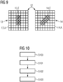
- the first emitter area 13.A and the second emitter area 14.A are each segmented in the form of a grid in an 8 ⁇ 8 matrix. In principle, it is conceivable that the number of rows differs from the number of columns. The number of rows or columns can be more than 8, for example, in particular 256, 512, 1024 or more.
- the embodiment in 9 shows in each case the proportion of the electron-emitting surface 13.E, 14.E, in that the respective electron-emitting and thus switched-on segments are marked with an X.
- the off segments not marked with X do not emit electrons.
- the portion of the electron-emitting surface 14.E is set non-axisymmetrically, for example as a function of the eye movement signal, in such a way that the resulting focal spot BF A , BF B is rotated relative to the grid-shaped segmentation.
- FIG. 1 shows a method for generating x-ray radiation for stereoscopic imaging using an x-ray tube 10 in a flowchart.
- Method step S100 characterizes the provision of an interpupillary distance of a user of the x-ray tube 10 in the form of the distance signal.
- the interpupillary distance can be determined, for example, using a camera.
- Method step S101 indicates a transmission of the distance signal to the interface of the x-ray tube 10.
- Method step S102 indicates a setting of the distance between the two focal spots, in particular in the control unit of X-ray tube 10.
- Step S103 indicates a consecutive generate the X-ray radiation for the stereoscopic imaging in the two spaced focal spots.
Abstract
Die Erfindung betrifft eine Röntgenröhre für eine stereoskopische Bildgebung, ein Verfahren zur Generierung von Röntgenstrahlung für eine stereoskopische Bildgebung sowie ein zugehöriges Computerprogrammprodukt.Die erfindungsgemäße Röntgenröhre für eine stereoskopische Bildgebung weist- ein evakuiertes Röntgenröhrengehäuse,- eine in dem Röntgenröhrengehäuse angeordnete Elektronenemittervorrichtung,- eine in dem Röntgenröhrengehäuse angeordnete Anodeneinheit zur Generierung von Röntgenstrahlung für die stereoskopische Bildgebung in Abhängigkeit von auf zwei Brennflecken eintreffenden Elektronen auf und- eine Steuereinheit,dadurch gekennzeichnet,- dass die erste Emitterfläche und die zweite Emitterfläche im Strahlengang der in dem jeweiligen Brennfleck generierten Röntgenstrahlung angeordnet sind sowie- dass die Steuereinheit zum Einstellen eines Abstands zwischen den beiden Brennflecken durch ein Vorgeben des Anteils der Elektronen-emittierenden Fläche der ersten Emitterfläche und/oder der zweiten Emitterfläche ausgebildet ist.The invention relates to an x-ray tube for stereoscopic imaging, a method for generating x-rays for stereoscopic imaging and an associated computer program product. The x-ray tube according to the invention for stereoscopic imaging has an evacuated x-ray tube housing, an electron emitter device arranged in the x-ray tube housing, X-ray tube housing arranged anode unit for generating X-rays for stereoscopic imaging as a function of electrons arriving at two focal points and- a control unit, characterized in that- the first emitter surface and the second emitter surface are arranged in the beam path of the X-rays generated in the respective focal point, and that the control unit for setting a distance between the two focal spots by specifying the proportion of the electron-emitting area of the first emitter area and/or the second emitter area is formed.
Description
Die Erfindung betrifft eine Röntgenröhre für eine stereoskopische Bildgebung, ein Verfahren zur Generierung von Röntgenstrahlung für eine stereoskopische Bildgebung sowie ein zugehöriges Computerprogrammprodukt.The invention relates to an x-ray tube for stereoscopic imaging, a method for generating x-ray radiation for stereoscopic imaging, and an associated computer program product.
Die in der medizinischen Bildgebung zu untersuchenden Objekte, insbesondere die Patienten, sind dreidimensional. Daher werden bei manchen Anwendungen Aufnahmen aus unterschiedlichen Richtungen des Patienten erfasst, um Informationen über die Tiefe zu erlangen. Solche Anwendungen im Bereich der Röntgenstrahlen-basierten Bildgebung finden beispielsweise in Computertomographie-Geräten oder in C-Bögen bei einer Angiographie statt.The objects to be examined in medical imaging, in particular the patients, are three-dimensional. Therefore, in some applications, images are acquired from different directions of the patient in order to obtain information about the depth. Such applications in the field of X-ray-based imaging take place, for example, in computed tomography devices or in C-arms in angiography.
Die räumliche Wahrnehmungsfähigkeit des Menschen wird bei diesen Anwendungen regelmäßig nicht ausreichend genutzt. Um diese Fähigkeit zu nutzen, sind zwei Röntgenaufnahmen mit einem geringen Winkelversatz nötig, was beispielsweise bereits in der
Eine Möglichkeit ist die Verwendung von zwei separaten herkömmlichen Drehanoden (siehe z.B.
Zwei Brennflecke auf einer einzigen Anode insbesondere durch Ablenkung des Elektronenstrahls unterzubringen, ist eine weitere aus dem Stand der Technik bekannte Alternative (
Den zuvor beschriebenen Ausführungen ist gemein, dass der nutzbare Aufenthaltsbereich der Brennflecke relativ klein ist. Dadurch kann der Abstand der Brennflecke typischerweise nur in einem sehr engen Bereich angepasst werden (weniger als +/- 5 mm). Der Augenabstand beträgt beim Menschen durchschnittlich 65 mm (Männer) bzw. 62 mm (Frauen), kann aber je nach Konstitution und Größe im Bereich zwischen ca. 52 mm und 78 mm variieren. Die bisher diesseits bekannten Ausführungen sind nicht in der Lage, den Abstand der Brennflecke so einzustellen, dass ein für den individuellen Betrachter optimiertes Bild entsteht. Dadurch kann unter Umständen die räumliche Wahrnehmungsfähigkeit trotz derartiger Röntgenaufnahmen nicht genutzt werden.What the previously described embodiments have in common is that the usable location area of the focal spots is relatively small. As a result, the distance between the focal spots can typically only be adjusted within a very narrow range (less than +/- 5 mm). The distance between the eyes in humans is on average 65 mm (men) or 62 mm (women), but can range between approx. 52 mm and 52 mm depending on the constitution and size 78mm vary. The previously known designs are not able to set the distance between the focal points in such a way that an image optimized for the individual viewer is created. As a result, the spatial perception ability may not be used despite such X-ray exposures.
Der Erfindung liegt die Aufgabe zu Grunde, eine Röntgenröhre für eine stereoskopische Bildgebung, ein Verfahren zur Generierung von Röntgenstrahlung für eine stereoskopische Bildgebung sowie ein zugehöriges Computerprogrammprodukt anzugeben, bei welchen der Abstand zwischen den Brennflecken in einem größeren Bereich einstellbar ist.The invention is based on the object of specifying an x-ray tube for stereoscopic imaging, a method for generating x-ray radiation for stereoscopic imaging and an associated computer program product in which the distance between the focal spots can be adjusted over a large range.
Die Aufgabe wird durch die Merkmale der unabhängigen Ansprüche gelöst. Vorteilhafte Ausgestaltungen sind in den Unteransprüchen beschrieben.The object is solved by the features of the independent claims. Advantageous configurations are described in the dependent claims.
Die erfindungsgemäße Röntgenröhre für eine stereoskopische Bildgebung weist
- ein evakuiertes Röntgenröhrengehäuse,
- eine in dem Röntgenröhrengehäuse angeordnete Elektronenemittervorrichtung,
- eine in dem Röntgenröhrengehäuse angeordnete Anodeneinheit zur Generierung von Röntgenstrahlung für die stereoskopische Bildgebung in Abhängigkeit von auf zwei Brennflecken eintreffenden Elektronen und
- eine Steuereinheit auf,
- wobei die Elektronenemittervorrichtung einen ersten Feldeffekt-Emitter mit einer ersten Emitterfläche und einen zweiten Feldeffekt-Emitter mit einer zweiten Emitterfläche umfasst,
- wobei die erste Emitterfläche und die zweite Emitterfläche ein im Wesentlichen Röntgenstrahlen-transparentes Material aufweisen,
- wobei die erste Emitterfläche und/oder die zweite Emitterfläche derart segmentiert ist, dass ein Anteil der Elektronen-emittierenden Fläche relativ zur jeweiligen gesamten Emitterfläche durch selektives Schalten der Emittersegmente einstellbar ist,
dadurch gekennzeichnet, - dass die erste Emitterfläche und die zweite Emitterfläche im Strahlengang der in dem jeweiligen Brennfleck generierten Röntgenstrahlung angeordnet sind sowie
- dass die Steuereinheit zum Einstellen eines Abstands zwischen den beiden Brennflecken durch ein Vorgeben des Anteils der Elektronen-emittierenden Fläche der ersten Emitterfläche und/oder der zweiten Emitterfläche ausgebildet ist.
- an evacuated X-ray tube housing,
- an electron emitter device arranged in the x-ray tube housing,
- an anode unit arranged in the x-ray tube housing for generating x-ray radiation for stereoscopic imaging as a function of electrons impinging on two focal spots and
- a control unit,
- wherein the electron emitter device comprises a first field effect emitter having a first emitter area and a second field effect emitter having a second emitter area,
- wherein the first emitter surface and the second emitter surface comprise a substantially X-ray transparent material,
- wherein the first emitter area and / or the second emitter area is segmented such that a proportion of the electron-emitting area relative to the respective total emitter area can be adjusted by selective switching of the emitter segments,
characterized, - that the first emitter surface and the second emitter surface are arranged in the beam path of the X-ray radiation generated in the respective focal spot, and
- that the control unit is designed to set a distance between the two focal spots by specifying the proportion of the electron-emitting surface of the first emitter surface and/or the second emitter surface.
Vorteilhafterweise kann die Elektronen-emittierende Fläche beliebig konfiguriert werden, so dass der Abstand zwischen den beiden Brennflecken über einen größeren Bereich einstellbar ist. Dies wird insbesondere dadurch ermöglicht, dass aufgrund der Segmentierung der Emitterflächen der Anteil der Elektronen-emittierenden Fläche flexibel einstellbar ist. Das bedeutet insbesondere, dass einzelne Segmente der ersten Emitterfläche und/oder der zweiten Emitterfläche angeschaltet oder abgeschaltet werden können, wodurch die Position der jeweiligen Elektronenströme variiert werden kann. Letztlich kann allein durch das Variieren der Position der Elektronen-emittierenden Fläche der ersten Emitterfläche oder der zweiten Emitterfläche der Abstand zwischen den beiden Brennflecken beeinflusst werden. Besonders vorteilhafterweise kann der Abstand über einen noch größeren Bereich beeinflusst werden, wenn beide Emitterflächen segmentiert sind.Advantageously, the electron-emitting surface can be configured as desired, so that the distance between the two focal spots can be adjusted over a larger range. This is made possible in particular by the fact that the proportion of the electron-emitting surface can be set flexibly due to the segmentation of the emitter surfaces. This means in particular that individual segments of the first emitter area and/or the second emitter area can be switched on or off, as a result of which the position of the respective electron streams can be varied. Ultimately, the distance between the two focal spots can be influenced solely by varying the position of the electron-emitting surface of the first emitter surface or of the second emitter surface. In a particularly advantageous manner, the distance can be influenced over an even larger area if both emitter surfaces are segmented.
Die Verwendung der Feldeffekt-Emitter ist insbesondere vorteilhaft, weil aufgrund deren hohen Elektronenstromdichte Fokussierungselemente und/oder Ablenkeinheiten regelmäßig verzichtbar sind. Außerdem weisen die Emitterflächen solcher Feldeffekt-Emitter üblicherweise das Röntgenstrahlen-transparente Material auf, so dass die Röntgenstrahlung beim Durchdringen der ersten Emitterfläche und der zweiten Emitterfläche vergleichsweise wenig abgeschwächt wird.The use of field-effect emitters is particularly advantageous because, due to their high electron current density, focusing elements and/or deflection units can generally be dispensed with. In addition, the emitter surfaces of such field-effect emitters usually have the X-ray-transparent material, so that the X-ray radiation is comparatively little weakened when it penetrates the first emitter surface and the second emitter surface.
Die Röntgenröhre ist insbesondere also für solche Röntgenstrahlen-basierte Anwendungen der stereoskopischen Bildgebung vorteilhaft, bei welchen die Röntgenstrahlen an verschiedenen Brennflecken konsekutiv erzeugt und somit mindestens zwei Aufnahmen aus unterschiedlichen Einfallwinkeln am Röntgendetektor erfasst werden, wobei die beiden Aufnahmen dann einem Nutzer angezeigt werden können, bei welchem dabei der räumliche Eindruck entsteht. Diese Anwendungen können insbesondere eine Angiographie oder Computertomographie betreffen.The X-ray tube is therefore particularly advantageous for those X-ray-based applications of stereoscopic imaging in which the X-rays are generated consecutively at different focal points and thus at least two recordings from different angles of incidence are recorded on the X-ray detector, with the two recordings then being able to be displayed to a user which creates the spatial impression. These applications can relate in particular to angiography or computed tomography.
Die Anodeneinheit umfasst mindestens eine Anode, kann je nach Ausführungsform lediglich eine einzige Anode umfassen. Die Anode ist typischerweise drehbar gelagert, so dass durch die bei der Drehung stattfindende Kühlung eine höhere Hubtemperatur ermöglicht wird und somit ein höherer Elektronenstrom auf der Anode als bei einer Stehanode auftreffen kann. Auf der Rückseite umfasst die Anode beispielsweise Grafit zur Entwärmung der Anodenoberfläche, welche im Bereich der Brennflecke beispielsweise Wolfram und/oder Molybdän aufweist.The anode unit comprises at least one anode, depending on the embodiment it can only comprise a single anode. The anode is typically rotatably mounted, so that the cooling that takes place during rotation enables a higher lifting temperature and thus a higher electron current can impinge on the anode than with a standing anode. On the back, the anode includes, for example, graphite for cooling the anode surface, which has, for example, tungsten and/or molybdenum in the area of the focal points.
Die Elektronen werden von der Elektronenemittervorrichtung Richtung der Anodeneinheit beschleunigt und generieren bei der Wechselwirkung in den beiden Brennflecken typischerweise konsekutiv die Röntgenstrahlung. Grundsätzlich kann die Röntgenröhre auch dazu ausgebildet sein, in beiden Brennflecken gleichzeitig Röntgenstrahlung generieren zu können. Die Brennflecke können Teil zumindest einer Brennbahn sein. Die generierte Röntgenstrahlung weist üblicherweise eine maximale Energie von bis zu 150 keV in Abhängigkeit von der zwischen der Elektronenemittervorrichtung und der Anodeneinheit angelegten Beschleunigungsspannung auf.The electrons are accelerated by the electron emitter device in the direction of the anode unit and typically generate the X-ray radiation consecutively during the interaction in the two focal spots. In principle, the x-ray tube can also be designed to be able to generate x-ray radiation in both focal spots at the same time. The focal spots can be part of at least one focal track. The x-ray radiation generated usually has a maximum energy of up to 150 keV depending on the acceleration voltage applied between the electron emitter device and the anode unit.
Eine äußere Form des ersten Brennflecks und/oder des zweiten Brennflecks kann grundsätzlich rund sein, ist regelmäßig allerdings nicht rund. Typischerweise ist die äußere Form viereckig, beispielsweise rechteckig oder rautenförmig. Typischerweise ist die äußere Form in radialer Richtung der Anode größer als in Phi-Richtung, d. h. in Umfangsrichtung der Anode.An outer shape of the first focal spot and/or the second focal spot can in principle be round, but is usually not round. Typically, the outer shape is square, such as rectangular or diamond-shaped. Typically, the outer shape is in the radial direction of the anode greater than in the Phi direction, ie in the circumferential direction of the anode.
Konsekutiv (oder alternierend) bedeutet, dass die generierte Röntgenstrahlung zu einem Auslesezeitpunkt jeweils einem Brennfleck zugeordnet werden kann. Eine Frequenz der konsekutiven Röntgenstrahlerzeugung kann auf eine Auslesefrequenz des Röntgendetektors abgestimmt sein, welcher typischerweise über einen gewissen Zeitraum die eintreffenden Photonen integriert, bevor eine Aufnahme zu einem bestimmten Auslesezeitpunkt erzeugt wird. Nach einer ersten Aufnahme zu einem ersten Auslesezeitpunkt mit der Röntgenstrahlung des ersten Brennflecks wird regelmäßig eine zweite Aufnahme zu einem zweiten Auslesezeitpunkt mit der Röntgenstrahlung des zweiten Brennflecks erfasst. Dieses konsekutive Generieren kann beliebig wiederholt werden, beispielsweise während der gesamten Dauer der bildgebenden Untersuchung erfolgen.Consecutive (or alternating) means that the x-ray radiation generated can be assigned to a respective focal spot at a point in time when it is read out. A frequency of the consecutive X-ray generation can be tuned to a readout frequency of the X-ray detector, which typically integrates the incoming photons over a certain period of time before a recording is generated at a specific readout time. After a first recording at a first readout time with the X-ray radiation of the first focal spot, a second recording is regularly recorded at a second readout time with the X-ray radiation of the second focal spot. This consecutive generation can be repeated as desired, for example over the entire duration of the imaging examination.
Das Röntgenröhrengehäuse kann Glas und/oder Metall umfassen. Falls die erste Emitterfläche und/oder die zweite Emitterfläche keinen Teil des Röntgenröhrengehäuses bilden, weist das Röntgenröhrengehäuse ein Röntgenstrahlenaustrittfenster insbesondere dort auf, wo der Strahlengang der in dem jeweiligen Brennfleck generierten Röntgenstrahlung aus dem Röntgenröhrengehäuse austreten soll. Das Röntgenröhrengehäuse ist typischerweise von einem Kühlmedium umgegeben.The x-ray tube housing may comprise glass and/or metal. If the first emitter surface and/or the second emitter surface do not form part of the x-ray tube housing, the x-ray tube housing has an x-ray exit window, particularly where the beam path of the x-ray radiation generated in the respective focal spot is intended to exit the x-ray tube housing. The x-ray tube housing is typically surrounded by a cooling medium.
Der erste Feldeffekt-Emitter und der zweite Feldeffekt-Emitter sind regelmäßig derart angeordnet, dass ein gewisser Abstand zwischen der ersten Emitterfläche und der zweiten Emitterfläche besteht. Der erste Feldeffekt-Emitter und der zweite Feldeffekt-Emitter können grundsätzlich derart angeordnet sein, dass die erste Emitterfläche und die zweite Emitterfläche eine im Wesentlichen zusammenhängende Emitterfläche bilden. In diesem Fall ist also ein Abstand zwischen den beiden Emitterflächen vorzugsweise minimal. Dabei sind der erste Feldeffekt-Emitter und der zweite Feldeffekt-Emitter physisch dadurch zu unterscheiden, dass jeder eine separate Plattform, beispielsweise in Form eines nicht-zusammenhängenden Substrats, aufweist.The first field effect emitter and the second field effect emitter are regularly arranged in such a way that there is a certain distance between the first emitter area and the second emitter area. In principle, the first field-effect emitter and the second field-effect emitter can be arranged in such a way that the first emitter area and the second emitter area form an essentially continuous emitter area. In this case, therefore, a distance between the two emitter surfaces is preferably minimal. In this case, the first field effect emitter and the second field effect emitter physically distinguishable in that each has a separate platform, e.g. in the form of a non-contiguous substrate.
Alternativ können der erste Feldeffekt-Emitter und der zweite Feldeffekt-Emitter physisch nicht unterscheidbar sein, sondern derart integriert auf einer einzigen Plattform ausgebildet sein, dass die Elektronenemittervorrichtung eine zusammenhängende Emitterfläche aufweist. In diesem Fall kann die Unterscheidung zwischen dem ersten Feldeffekt-Emitter und dem zweiten Feldeffekt-Emitter dadurch erfolgen, dass softwareseitig oder elektronisch diese zusammenhängende Emitterfläche in zwei nebeneinander angeordnete Teilbereiche unterteilt ist, wobei der erste Teilbereich die erste Emitterfläche und der zweite Teilbereich die zweite Emitterfläche bildet. In diesem Fall ist es denkbar, dass die erste Emitterfläche und die zweite Emitterfläche innerhalb der zusammenhängenden Emitterfläche neu verteilt werden kann.Alternatively, the first field-effect emitter and the second field-effect emitter may not be physically distinguishable but may be integrally formed on a single platform such that the electron emitter device has a contiguous emitter area. In this case, the distinction between the first field-effect emitter and the second field-effect emitter can be made by dividing this contiguous emitter surface into two adjacent sub-areas by software or electronically, with the first sub-area being the first emitter surface and the second sub-area being the second emitter surface forms. In this case it is conceivable that the first emitter area and the second emitter area can be redistributed within the contiguous emitter area.
Es ist vorteilhaft, wenn die erste Emitterfläche und die zweite Emitterfläche im Sinne eines maximal emittierbaren Elektronenstroms vergleichbar sind. Die Segmentierung der beiden Emitterflächen kann homogen sein, sprich sie können in im Wesentlichen gleich leistungsfähige mehrere Elektronenstrom-Emissionsbereiche unterteilt sein, oder heterogen sein. Die Segmentierung kann rasterförmig oder kreissegmentförmig sein. Die rasterförmige Segmentierung kann einer pixelartigen Segmentierung entsprechen mit vorzugsweise gleich großen Pixeln. Es ist besonders vorteilhaft, wenn eine elektrische Kontaktierung der beiden Emissionsflächen durch den jeweiligen Feldeffekt-Emitter vorzugsweise derart ausgestaltet ist, dass Röntgenstrahlen-intransparente Materialien sich weitestgehend außerhalb des Strahlengangs befinden.It is advantageous if the first emitter area and the second emitter area are comparable in terms of a maximum electron current that can be emitted. The segmentation of the two emitter surfaces can be homogeneous, ie they can be subdivided into several electron current emission regions with substantially the same performance, or they can be heterogeneous. The segmentation can be in the form of a grid or a segment of a circle. The grid-like segmentation can correspond to a pixel-like segmentation, preferably with pixels of the same size. It is particularly advantageous if electrical contacting of the two emission surfaces by the respective field effect emitter is preferably designed in such a way that materials that are opaque to X-rays are largely located outside the beam path.
Die gesamte Emitterfläche wird jeweils durch die erste Emitterfläche oder die zweite Emitterfläche vorgegeben. Die zusammenhängende Emitterfläche entspricht der gesamten Emitterfläche der ersten Emitterfläche plus der gesamten Emitterfläche der zweiten Emitterfläche. Die Elektronen-emittierende Fläche ist als diejenige Fläche definiert, aus welcher Elektronen die jeweilige Emitterfläche verlassen und insbesondere ohne Abschwächung durch ein Sperrgitter auf der Anodeneinheit auftreffen können. Der Anteil der Elektronen-emittierenden Fläche relativ zur jeweiligen gesamten Emitterfläche kann zwischen 0%, insbesondere wenn in diesem Moment in dem jeweils anderen Brennfleck Röntgenstrahlung generiert wird, und 100%, insbesondere wenn in einem anderen Moment in dem zugeordneten Brennfleck die Röntgenstrahlung generiert wird, liegen. Typischerweise wird der Anteil bei Röntgenstrahlerzeugung kleiner 100% sein, beispielsweise in einem Bereich zwischen 0,5% und 50% sein, insbesondere 2% betragen, so dass die Elektronen-emittierende Fläche innerhalb der jeweiligen gesamten Emitterfläche bei gleichbleibender Intensität des Elektronenstroms verschoben werden kann.The entire emitter area is specified in each case by the first emitter area or the second emitter area. The contiguous emitter area corresponds to the total emitter area of the first emitter area plus the total emitter area of the second emitter area. The electron-emitting area is defined as that area from which electrons can leave the respective emitter area and, in particular, can strike the anode unit without being weakened by a blocking grid. The proportion of the electron-emitting area relative to the respective total emitter area can be between 0%, in particular if X-rays are generated in the other focal spot at this moment, and 100%, in particular if the X-rays are generated in the associated focal spot at a different moment, lay. Typically, the proportion in X-ray generation will be less than 100%, for example in a range between 0.5% and 50%, in particular 2%, so that the electron-emitting area can be shifted within the respective entire emitter area with the intensity of the electron current remaining the same .
Die Elektronenemission bei Feldeffekt-Emitter wird typischerweise durch das Anlegen einer Gatespannung erwirkt, welche durch das in den Spitzen der Nanoröhrchen auftretenden elektrischen Felds die Elektronen aus diesen Nanoröhren extrahiert, wodurch der Elektronenstrom gebildet wird. Zusätzlich zum Schalten mittels der Gatespannung kann das Sperren eines generierten Elektronenstroms mittels eines Sperrgitters erfolgen. Das selektive Schalten der Emittersegmente umfasst zumindest das Anlegen der Gatespannung und optional das Anlegen einer Sperrspannung am Sperrgitter. Das selektive Schalten umfasst also insbesondere das Anschalten und das Abschalten, beispielsweise der angelegten Gatespannung und/oder der den Nanoröhrchen vorgeschalteten Strombegrenzungseinheiten. Selektiv schaltbar bedeutet insbesondere, dass vorzugsweise jedes Emittersegment separat anschaltbar oder abschaltbar ist. Jedes Emittersegment weist typischerweise eine Vielzahl an Nanoröhrchen auf. Die Struktur, an welchem typischerweise die Gatespannung anliegt, weist vorzugweise ebenfalls ein Röntgenstrahlen-transparentes Material, insbesondere ein Röntgenstrahlen-transparentes Metall, auf, beispielsweise Aluminium. Das Röntgenstrahlen-transparente Material kann eine leitfähige Siliziumstruktur, insbesondere amorphes Silizium sein.Electron emission in field effect emitters is typically achieved by applying a gate voltage, which extracts the electrons from these nanotubes through the electric field occurring in the tips of the nanotubes, whereby the electron current is formed. In addition to switching by means of the gate voltage, a generated electron current can be blocked by means of a blocking grid. The selective switching of the emitter segments comprises at least the application of the gate voltage and optionally the application of a blocking voltage to the blocking grid. The selective switching thus includes, in particular, switching on and off, for example the applied gate voltage and/or the current-limiting units connected upstream of the nanotubes. Selectively switchable means in particular that preferably each emitter segment can be switched on or off separately. Each emitter segment typically has a large number of nanotubes. The structure to which the gate voltage is typically applied preferably also has a material that is transparent to X-rays, in particular a material X-ray transparent metal, on e.g. aluminium. The X-ray transparent material can be a conductive silicon structure, in particular amorphous silicon.
Die Röntgenröhre und/oder die Elektronenemittervorrichtung kann einen Logikbaustein umfassen, in welchem die Steuereinheit und/oder eine weitere Steuereinheit und/oder eine Schnittstelle integriert sind. Dieser Logikbaustein dient insbesondere einer Steuerung der Elektronenemission der Elektronenemittervorrichtung mittels der ersten Emitterfläche und der zweiten Emitterfläche. Der Logikbaustein, insbesondere die Steuereinheit, kann dazu ausgebildet sein, den Anteil der Elektronen-emittierenden Fläche relativ zur jeweiligen gesamten Emitterfläche einzustellen, beispielsweise indem der Logikbaustein die Emittersegmente selektiv schaltet. Der Logikbaustein kann ein FPGA-Baustein oder ein Prozessor sein.The X-ray tube and/or the electron emitter device can comprise a logic module in which the control unit and/or a further control unit and/or an interface are integrated. This logic module serves in particular to control the electron emission of the electron emitter device by means of the first emitter area and the second emitter area. The logic module, in particular the control unit, can be designed to set the proportion of the electron-emitting area relative to the respective total emitter area, for example by the logic module switching the emitter segments selectively. The logic module can be an FPGA module or a processor.
Da die Röntgenstrahlung üblicherweise konsekutiv in den beiden Brennflecken erzeugt wird, bezieht sich der Abstand beispielsweise auf den einen, soeben für die Röntgenstrahlungserzeugung genutzten Brennfleck, sowie auf den anderen, vorher genutzten oder nachher zu nutzenden Brennfleck. Der Abstand kann beispielsweise durch eine äußere Begrenzungslinie oder einem Intensitätsschwerpunkt oder einem geometrischen Mittelpunkt der beiden Brennflecke definiert sein. In Bezug auf den medizinisch definierten Augenabstand als Distanz der beiden Pupillen, beziehen sich die in der vorliegenden Schrift angegebenen Abstände auf den jeweiligen geometrischen Mittelpunkt der beiden Brennflecke.Since the x-ray radiation is usually generated consecutively in the two focal spots, the distance relates, for example, to the one focal spot just used for the x-ray radiation generation and to the other focal spot used beforehand or to be used afterwards. The distance can be defined, for example, by an outer boundary line or a center of intensity or a geometric center of the two focal points. With regard to the medically defined interpupillary distance as the distance between the two pupils, the distances specified in this document relate to the respective geometric center of the two focal points.
Das Einstellen des Abstands bedeutet insbesondere ein Verändern und/oder individuelles Regeln des Abstands. Das Einstellen des Abstands zwischen den beiden Brennflecken kann mittels der Steuereinheit dadurch erfolgen, dass der Anteil der Elektronen-emittierenden Fläche einer einzigen Emitterfläche oder beider Emitterflächen eingestellt wird. Das Vorgeben des Anteils der Elektronen-emittierenden Fläche der ersten Emitterfläche und/oder der zweiten Emitterfläche kann ein Bereitstellen eines Steuersignals und/oder das selektive Schalten, also das Abschalten und/oder Anschalten der Emittersegmente, umfassen.Adjusting the distance means, in particular, changing and/or individually regulating the distance. The distance between the two focal spots can be set by means of the control unit by setting the proportion of the electron-emitting surface of a single emitter surface or of both emitter surfaces. The specification of The proportion of the electron-emitting area of the first emitter area and/or the second emitter area can include providing a control signal and/or selectively switching, ie switching the emitter segments off and/or on.
Der Abstand kann beispielsweise dadurch verringert werden, dass ein zentrales Emittersegment zugeschaltet wird, welches in einem zentralen Bereich zwischen den beiden Brennflecken liegt, und/oder dass ein dezentrales Emittersegment abgeschaltet wird, welches außerhalb des zentralen Bereichs zwischen den beiden Brennflecken liegt. Das Zuschalten des zentralen Emittersegments verändert üblicherweise nicht eine maximale Ausdehnung der Elektronen-emittierenden Fläche, gemessen über beide Brennflecke. Das Abschalten des dezentralen Emittersegments verringert typischerweise die maximale Ausdehnung der Elektronen-emittierenden Fläche, gemessen über beide Brennflecke.The distance can be reduced, for example, by switching on a central emitter segment that lies in a central area between the two focal spots and/or by switching off a decentralized emitter segment that lies outside of the central area between the two focal spots. Switching on the central emitter segment usually does not change a maximum extent of the electron-emitting surface, measured over both focal spots. Turning off the decentralized emitter segment typically reduces the maximum extent of the electron-emitting area measured across both focal spots.
Dass die erste Emitterfläche und die zweite Emitterfläche im Strahlengang der in dem jeweiligen Brennfleck generierten Röntgenstrahlung angeordnet sind, bedeutet insbesondere, dass der Nutzanteil an Röntgenstrahlung zumindest teilweise die jeweilige Emitterfläche durchdringt bevor diese auf dem Röntgendetektor detektierbar ist. Die erste Emitterfläche und die zweite Emitterfläche schwächen die an dem jeweiligen Brennfleck generierte Röntgenstrahlung, insbesondere deren Nutzanteil, wenigstens minimal ab, weil physikalisch betrachtet das Röntgenstrahlen-transparente Material nicht zu 100% transparent ist. Der Strahlengang umfasst also insbesondere diejenigen Röntgenphotonen, welche unter der Annahme, dass keine Streuung im durchleuchteten Objekt stattfindet, in einer gerade Linie vom Brennfleck in Richtung des Röntgendetektors propagieren. Diejenigen Röntgenphotonen bzw. der Nutzanteil an Röntgenstrahlung werden regelmäßig Fokalstrahlung genannt. In anderen Worten wird die erste Emitterfläche und die zweite Emitterfläche nicht ausschließlich von sogenannter Extrafokalstrahlung durchdrungen. Die Extrafokalstrahlung wird beispielsweise durch die Ausgestaltung des Röntgenstrahlenaustrittfensters und/oder durch einen Kollimator und/oder durch ein Streustrahlenraster vor dem Röntgendetektor abgeschirmt. Die erste Emitterfläche und die zweite Emitterfläche sind also jeweils das erste Objekt im Strahlengang, in welchem sogenannte Streustrahlung entstehen kann.The fact that the first emitter surface and the second emitter surface are arranged in the beam path of the x-ray radiation generated in the respective focal spot means in particular that the useful portion of x-ray radiation at least partially penetrates the respective emitter surface before it can be detected on the x-ray detector. The first emitter surface and the second emitter surface weaken the x-ray radiation generated at the respective focal point, in particular its useful portion, at least minimally, because from a physical point of view the x-ray transparent material is not 100% transparent. The beam path therefore includes, in particular, those x-ray photons which propagate in a straight line from the focal spot in the direction of the x-ray detector, assuming that no scattering takes place in the transilluminated object. Those X-ray photons or the useful portion of X-ray radiation are regularly called focal radiation. In other words, the first emitter area and the second emitter area is not exclusively of so-called Extrafocal radiation penetrated. The extrafocal radiation is shielded, for example, by the configuration of the x-ray exit window and/or by a collimator and/or by a scattered radiation grid in front of the x-ray detector. The first emitter surface and the second emitter surface are therefore each the first object in the beam path in which so-called scattered radiation can occur.
Eine Ausführungsform sieht vor, dass das Röntgenstrahlen-transparente Material Silizium ist. Silizium-Feldeffekt-Emitter sind besonders vorteilhaft, weil diese aufgrund einer gut zu integrierenden Strombegrenzungseinheit besonders widerstandsfähig und somit langlebig sind.One embodiment provides that the X-ray transparent material is silicon. Silicon field effect emitters are particularly advantageous because they are particularly resistant and therefore durable due to a current-limiting unit that can be easily integrated.
Eine Ausführungsform sieht vor, dass die erste Emitterfläche und/oder die zweite Emitterfläche ein vakuumdichtes Gehäuseteil des Röntgenröhrengehäuses bilden. Diese Ausführungsform kann insbesondere bedeuten, dass das Röntgenröhrengehäuse im Bereich des Strahlengangs der in dem jeweiligen Brennfleck generierten Röntgenstrahlung durchbrochen ist und die in so einer Aussparung eingesetzten Emitterflächen das Vakuum des Röntgenröhrengehäuse aufrechterhalten können. Das durchbrochene Röntgenröhrengehäuse sowie die erste Emitterfläche und/oder die zweite Emitterfläche können also vorteilhafterweise das Vakuum innerhalb des Röntgenröhrengehäuse erhalten. Daraus folgt eine vorteilhafte geringere Bauform und aufgrund der Materialersparnis ein vorzugsweise geringeres Gewicht, als wenn das Röntgenstrahlergehäuse zusätzlich zumindest ein herkömmliches Röntgenstrahlungaustrittfenster aufweist.One embodiment provides that the first emitter surface and/or the second emitter surface form a vacuum-tight housing part of the x-ray tube housing. This embodiment can mean in particular that the x-ray tube housing is broken in the area of the beam path of the x-rays generated in the respective focal spot and the emitter surfaces inserted in such a recess can maintain the vacuum of the x-ray tube housing. The perforated x-ray tube housing and the first emitter surface and/or the second emitter surface can thus advantageously maintain the vacuum within the x-ray tube housing. This results in an advantageous smaller design and, due to the saving in material, a preferably lower weight than when the x-ray emitter housing additionally has at least one conventional x-ray radiation exit window.
Eine Ausführungsform sieht vor, dass ein Fokuskopf des ersten Feldeffekt-Emitters und/oder des zweiten Feldeffekt-Emitters Aluminium aufweist. Wenn die Röntgenröhre den Fokuskopf aufweist, kann dieser insbesondere aus Aluminium bestehen. Aluminium ist ein Röntgenstrahlen-transparentes Metall und somit besonders für den Einsatz im Fokuskopf, welcher sich als Teil der Elektronenemittervorrichtung zumindest teilweise im Strahlengang der Röntgenstrahlung befinden kann, geeignet. Der Fokuskopf ist vorteilhafterweise vergleichsweise dünn ausgeführt und/oder eher parallel zur Röntgenstrahlung ausgebildet.One embodiment provides that a focus head of the first field effect emitter and/or the second field effect emitter has aluminum. If the x-ray tube has the focus head, this can consist in particular of aluminum. Aluminum is an X-ray transparent metal and thus particularly suitable for use in the focus head, which is at least partially in the electron emitter device as part of the Beam path of the X-ray radiation can be suitable. The focus head is advantageously designed to be comparatively thin and/or designed more parallel to the x-ray radiation.
Eine Ausführungsform sieht vor, dass die Röntgenröhre ferner eine Schnittstelle zum Empfang eines Abstandsignals, welches mit dem Abstand zwischen den Brennflecken korreliert, aufweist. Die Schnittstelle kann insbesondere Teil der Steuereinheit oder des Logikbausteins sein. Die Schnittstelle ermöglicht vorteilhafterweise das Vorgeben des Abstandssignals von extern an die Röntgenröhre, so dass der Abstand zwischen den beiden Brennfleck individuell angepasst werden kann.One embodiment provides that the x-ray tube also has an interface for receiving a distance signal which correlates with the distance between the focal spots. In particular, the interface can be part of the control unit or the logic module. The interface advantageously allows the distance signal to be specified externally to the X-ray tube, so that the distance between the two focal spots can be individually adjusted.
Eine Ausführungsform sieht vor, dass die Röntgenröhre ferner eine weitere Schnittstelle zum Empfang eines Blickbewegungssignals und eine weitere Steuereinheit zum derartigen nicht-achsensymmetrischen Einstellen des Anteils der Elektronen-emittierenden Fläche in Abhängigkeit des Blickbewegungssignals aufweist, dass zumindest einer der beiden Brennflecke relativ zur rasterförmigen Segmentierung verdreht ist. Die weitere Steuereinheit kann ebenso wie die Steuereinheit als Teil des Logikbausteins ausgebildet sein. Die Steuereinheit und die weitere Steuereinheit können insbesondere softwaretechnisch abgebildet und/oder unterscheidbar sein. Das Blickbewegungssignals kann insbesondere mit einer Beobachtungsachse des Betrachters korrelieren oder diese angeben.One embodiment provides that the X-ray tube also has an additional interface for receiving an eye movement signal and an additional control unit for such non-axisymmetric adjustment of the proportion of the electron-emitting surface as a function of the eye movement signal that at least one of the two focal spots rotates relative to the grid-shaped segmentation is. Like the control unit, the further control unit can also be designed as part of the logic module. The control unit and the further control unit can, in particular, be mapped and/or distinguished by software. In particular, the eye movement signal can correlate with an observation axis of the observer or indicate this.
Eine Ausführungsform sieht vor, dass die Anodeneinheit eine einzige drehbar gelagerte Scheibenanode aufweist, deren Oberfläche im Bereich der Brennflecke im Wesentlichen einen Tellerwinkel von 0° aufweist, und dass die Scheibenanode somit zumindest abschnittsweise flach ist. Einzig heißt, dass beide Brennflecke auf derselben Scheibenanode angeordnet sind. Dass die Scheibenanode flach ist, bedeutet insbesondere, dass relativ zu einem Drehachsenabschnitt zwischen zwei Kreisen mit unterschiedlichen Radien der Tellerwinkel 0° ist und in dem Bereich zwischen den beiden Kreisen die Brennflecke liegen. In einem besonderen Beispiel ist die Scheibenanode komplett flach, wobei der eine Radius dem Radius des Umfangs der Scheibenanode entspricht und der zweite Radius gleich null ist. Der Vorteil einer solchen flachen Scheibenanode ist insbesondere, dass einer der beiden Brennflecke oder beide Brennflecke beliebig innerhalb der flachen Abschnitte der Scheibenanode verschoben werden können.One embodiment provides that the anode unit has a single rotatably mounted disc anode, the surface of which essentially has a plate angle of 0° in the area of the focal spots, and that the disc anode is therefore flat at least in sections. Single means that both focal spots are arranged on the same disc anode. The fact that the disk anode is flat means in particular that relative to a rotational axis section between two circles with different radii the disk angle is 0° and in which Area between the two circles are the focal spots. In a particular example, the disc anode is completely flat, with one radius equal to the radius of the perimeter of the disc anode and the second radius being zero. The particular advantage of such a flat disk anode is that one of the two focal spots or both focal spots can be shifted as desired within the flat sections of the disk anode.
Eine in Bezug auf die vorherige Ausführungsform bevorzugte Ausführungsform sieht vor, dass die Anodeneinheit relativ zur ersten Emitterfläche und zur zweiten Emitterfläche derart gekippt angeordnet ist, dass sich eine erste Ebene, welche die erste Emitterfläche und die zweite Emitterfläche umfasst, sowie eine zweite Ebene, welche die flachen Abschnitte mit den Brennflecken umfasst, sich geometrisch schneiden. In anderen Worten sind die erste Ebene und die zweite Ebene nicht parallel. Die Definition der Ebenen dient insbesondere der Veranschaulichung der geometrischen Anordnung zueinander. Diese Ausführungsform ist insbesondere vorteilhaft, weil dadurch auf der Scheibenanode mehr elektrische Leistung in Form eines höheren Elektronenstroms deponiert werden kann.An embodiment that is preferred in relation to the previous embodiment provides that the anode unit is arranged tilted relative to the first emitter surface and the second emitter surface such that a first plane, which comprises the first emitter surface and the second emitter surface, and a second plane, which includes the flat sections with the focal spots, geometrically intersect. In other words, the first level and the second level are not parallel. The definition of the planes serves in particular to illustrate the geometric arrangement in relation to one another. This embodiment is particularly advantageous because it allows more electrical power to be deposited on the disk anode in the form of a higher electron current.
Eine alternative Ausführungsform sieht vor, dass die Anodeneinheit eine einzige drehbar gelagerte Walzenanode mit einer zylindrischen Mantelfläche aufweist und dass die Brennflecke entlang der Mantelfläche axial versetzt angeordnet sind. Einzig heißt, dass beide Brennflecke auf derselben Walzenanode angeordnet sind. Die Walzenanode bietet den Vorteil, dass eine höhere Leistung in Form eines höheren Elektronenstroms eingesetzt werden kann. Diese Ausführungsform ist insbesondere vorteilhaft, wenn zusätzlich die weitere Steuereinheit zum nicht-achsensymmetrischen Einstellen des Anteils der Elektronen-emittierenden Fläche in Abhängigkeit des Blickbewegungssignals vorgesehen ist.An alternative embodiment provides that the anode unit has a single rotatably mounted roller anode with a cylindrical lateral surface and that the focal spots are arranged axially offset along the lateral surface. Single means that both focal spots are arranged on the same roller anode. The roller anode offers the advantage that higher power can be used in the form of a higher electron current. This embodiment is particularly advantageous if, in addition, the further control unit is provided for non-axisymmetric adjustment of the proportion of the electron-emitting surface as a function of the eye movement signal.
Eine zu den vorherigen Ausführungsformen alternative Ausführungsform mit zwei Anoden sieht vor, dass die Anodeneinheit eine drehbar gelagerte Telleranode, deren Oberfläche im Bereich eines Brennflecks einen Tellerwinkel größer 0° aufweist, sowie eine weitere Anode aufweist, wobei die beiden Brennflecke auf die Telleranode und die weitere Anode verteilt sind. Bei dieser Ausführungsform ist üblicherweise die Position des einen Brennflecks fest und insbesondere die Position des anderen Brennflecks veränderbar. Die Verwendung der Telleranode mit dem Tellerwinkel größer 0° ermöglicht vorzugsweise eine relativ hohe Elektronenstrahlleistung insbesondere auch für Anwendungen, bei denen keine stereoskopische Bildgebung erforderlich ist, beispielsweise für Kontrollscans zur Dokumentation von medizinischen Eingriffen. Diese Ausführungsform kann vorteilhafterweise einen noch größeren Abstand zwischen den beiden Brennflecken ermöglichen.An alternative to the previous embodiments The embodiment with two anodes provides that the anode unit has a rotatably mounted plate anode whose surface has a plate angle greater than 0° in the area of a focal spot, and a further anode, with the two focal spots being distributed between the plate anode and the further anode. In this embodiment, the position of one focal point is usually fixed and, in particular, the position of the other focal point can be changed. The use of the disk anode with the disk angle greater than 0° preferably enables a relatively high electron beam power, in particular also for applications in which no stereoscopic imaging is required, for example for control scans for the documentation of medical interventions. This embodiment can advantageously allow an even greater distance between the two focal spots.
Eine zur vorherigen Ausführungsform bevorzugte Ausführungsform sieht vor, dass die Telleranode derart ausgerichtet ist, dass deren Rotationsachse parallel zu einer Ebene ist, welche die erste Emitterfläche und die zweite Emitterfläche umfasst. Diese Ausführungsform ermöglicht eine besonders kompakte Bauform einer Röntgenröhre mit zwei Anoden insofern, weil ein Abstand zwischen den beiden Anoden verringert werden kann.An embodiment that is preferred compared to the previous embodiment provides that the plate anode is aligned in such a way that its axis of rotation is parallel to a plane that includes the first emitter surface and the second emitter surface. This embodiment enables an X-ray tube with two anodes to have a particularly compact design, since a distance between the two anodes can be reduced.
Eine Ausführungsform als Weiterbildung einer der beiden vorherigen Ausführungsformen sieht vor, dass die weitere Anode eine Stehanode oder eine drehbar gelagerte Scheibenanode ist, deren Oberfläche im Bereich des einen Brennflecks im Wesentlichen einen Tellerwinkel von 0° aufweist, und somit zumindest abschnittsweise flach ist. Wenn die Stehanode oder die Scheibenanode flach ist, kann der dieser Anode zugeordnete Brennfleck über einen größeren Bereich verschoben und somit entsprechend der Abstand flexibler eingestellt werden.An embodiment as a further development of one of the two previous embodiments provides that the additional anode is a standing anode or a rotatably mounted disc anode, the surface of which essentially has a plate angle of 0° in the area of one focal spot and is therefore flat at least in sections. If the standing anode or the disc anode is flat, the focal spot assigned to this anode can be shifted over a larger area and the distance can thus be set more flexibly accordingly.
Das erfindungsgemäße Verfahren zur Generierung von Röntgenstrahlung für eine stereoskopische Bildgebung mittels einer Röntgenröhre umfasst die folgende Schritte:
- Bereitstellen eines Augenabstands eines Nutzers der Röntgenröhre in Form des Abstandsignals,
- Übermitteln des Abstandsignals an die Schnittstelle der Röntgenröhre,
- Einstellen des Abstands zwischen den beiden Brennflecken und
- Konsekutives generieren der Röntgenstrahlung für die stereoskopische Bildgebung in den beiden beabstandeten Brennflecken.
- providing an eye distance of a user of the x-ray tube in the form of the distance signal,
- transmitting the distance signal to the interface of the x-ray tube,
- Adjusting the distance between the two focal spots and
- Consecutive generation of the X-ray radiation for the stereoscopic imaging in the two spaced focal spots.
Der Nutzer der Röntgenröhre ist insbesondere ein Arzt oder eine andere entsprechend geschulte Person, welche die Röntgenröhre während einer medizinischen Anwendung verwendet, um beispielsweise einen Patienten mittels der Röntgenstrahlung für die stereoskopische Bildgebung zu untersuchen. Das Bereitstellen kann ein Abrufen eines Werts, der den Augenabstand beschreibt, aus einer Speichereinheit oder das Erfassen oder ein manuelles Eingeben des Augenabstands umfassen. Das Bereitstellen des Augenabstands kann insbesondere eine Blickbewegungsverfolgung, auch "eye-tracking" genannt, umfassen. Zusätzlich zum Augenabstand kann die Blickbewegung in Form des Blickbewegungssignals bereitgestellt werden. Das Übermitteln des Abstandssignals an die Schnittstelle der Röntgenröhre erfolgt typischerweise mittels einer Sendeeinheit, welche mit der Schnittstelle über eine drahtlose oder drahtgebundene Empfangseinheit verbunden wird. Daraufhin wird der Anteil der Elektronen-emittierenden Fläche relativ zur jeweiligen gesamten Emitterfläche durch selektives Schalten der Emittersegmente eingestellt, wodurch der Abstand zwischen den beiden Brennflecken eingestellt wird. Dieser Abstand kann insbesondere wiederholt eingestellt und/oder mehrfach verändert werden. Nach dem Einstellen der Elektronen-emittierenden Fläche wird die Röntgenstrahlung für die stereoskopische Bildgebung in den beiden beabstandeten Brennflecken konsekutiv generiert.The user of the x-ray tube is in particular a doctor or another appropriately trained person who uses the x-ray tube during a medical application, for example to examine a patient using the x-ray radiation for stereoscopic imaging. The providing may include retrieving a value describing the interpupillary distance from a storage unit or acquiring or manually entering the interpupillary distance. The provision of the distance between the eyes can, in particular, include eye movement tracking, also referred to as “eye-tracking”. In addition to eye relief, eye movement can be provided in the form of the eye movement signal. The distance signal is typically transmitted to the interface of the x-ray tube by means of a transmitter unit, which is connected to the interface via a wireless or wired receiver unit. The proportion of the electron-emitting area relative to the respective total emitter area is then adjusted by selectively switching the emitter segments, as a result of which the distance between the two focal spots is adjusted. This distance can in particular be set repeatedly and/or changed multiple times. After setting the electron-emitting surface, the X-ray radiation for the stereoscopic imaging is generated consecutively in the two spaced focal spots.
Eine Ausführungsform sieht vor, dass der Augenabstand mittels einer Kamera ermittelt wird. Diese Ausführungsform ist insbesondere vorteilhaft, weil die Kamera ein hochfrequentes und somit schnelles Erfassen des Augenabstands ermöglicht.One embodiment provides that the interpupillary distance by means a camera is detected. This embodiment is particularly advantageous because the camera enables the distance between the eyes to be detected at high frequency and therefore quickly.
Das Computerprogrammprodukt kann ein Computerprogramm sein oder ein Computerprogramm umfassen. Das Computerprogrammprodukt weist insbesondere die Programmcodemittel auf, welche die erfindungsgemäßen Verfahrensschritte abbilden. Dadurch kann das erfindungsgemäße Verfahren definiert und wiederholbar ausgeführt sowie eine Kontrolle über eine Weitergabe des erfindungsgemäßen Verfahrens ausgeübt werden. Das Computerprogrammprodukt ist vorzugsweise derart konfiguriert, dass die Recheneinheit mittels des Computerprogrammprodukts die erfindungsgemäßen Verfahrensschritte ausführen kann. Die Programmcodemittel können insbesondere in einen Speicher der Recheneinheit geladen und typischerweise mittels eines Prozessors der Recheneinheit mit Zugriff auf den Speicher ausgeführt werden. Wenn das Computerprogrammprodukt, insbesondere die Programmcodemittel, in der Recheneinheit ausgeführt wird, können typischerweise alle erfindungsgemäßen Ausführungsformen des beschriebenen Verfahrens durchgeführt werden. Das Computerprogrammprodukt ist beispielsweise auf einem physischen, computerlesbaren Medium gespeichert und/oder digital als Datenpaket in einem Computernetzwerk hinterlegt. Das Computerprogrammprodukt kann das physische, computerlesbare Medium und/oder das Datenpaket in dem Computernetzwerk darstellen. So kann die Erfindung auch von dem physischen, computerlesbaren Medium und/oder dem Datenpaket in dem Computernetzwerk ausgehen. Das physische, computerlesbare Medium ist üblicherweise unmittelbar mit der Recheneinheit verbindbar, beispielsweise indem das physische, computerlesbare Medium in ein DVD-Laufwerk eingelegt oder in einen USB-Port gesteckt wird, wodurch die Recheneinheit auf das physische, computerlesbare Medium insbesondere lesend zugreifen kann. Das Datenpaket kann vorzugsweise aus dem Computernetzwerk abgerufen werden. Das Computernetzwerk kann die Recheneinheit aufweisen oder mittels einer Wide-Area-Network- (WAN) bzw. einer (Wireless-)Local-Area-Network-Verbindung (WLAN oder LAN) mit der Recheneinheit mittelbar verbunden sein. Beispielsweise kann das Computerprogrammprodukt digital auf einem Cloud-Server an einem Speicherort des Computernetzwerks hinterlegt sein, mittels des WAN über das Internet und/oder mittels des WLAN bzw. LAN auf die Recheneinheit insbesondere durch das Aufrufen eines Downloadlinks, welcher zu dem Speicherort des Computerprogrammprodukts verweist, übertragen werden.The computer program product can be a computer program or can comprise a computer program. The computer program product has, in particular, the program code means that map the method steps according to the invention. As a result, the method according to the invention can be defined and executed in a repeatable manner, and control over the transfer of the method according to the invention can be exercised. The computer program product is preferably configured in such a way that the computing unit can carry out the method steps according to the invention using the computer program product. In particular, the program code means can be loaded into a memory of the processing unit and typically executed by means of a processor of the processing unit with access to the memory. If the computer program product, in particular the program code means, is executed in the computing unit, typically all embodiments according to the invention of the method described can be carried out. The computer program product is stored, for example, on a physical, computer-readable medium and/or stored digitally as a data package in a computer network. The computer program product can represent the physical, computer-readable medium and/or the data package on the computer network. The invention can also start from the physical, computer-readable medium and/or the data packet in the computer network. The physical, computer-readable medium can usually be connected directly to the processing unit, for example by inserting the physical, computer-readable medium into a DVD drive or plugging it into a USB port, which means that the processing unit can read the physical, computer-readable medium in particular. The data packet can preferably be retrieved from the computer network. The computer network can have the computing unit or by means of a wide area network (WAN) or a (Wireless) local area network connection (WLAN or LAN) to be indirectly connected to the processing unit. For example, the computer program product can be stored digitally on a cloud server at a storage location of the computer network, by means of the WAN via the Internet and/or by means of the WLAN or LAN to the processing unit, in particular by calling up a download link that refers to the storage location of the computer program product , be transmitted.
Bei der Beschreibung der Vorrichtung erwähnte Merkmale, Vorteile oder alternative Ausführungsformen sind ebenso auf das Verfahren zu übertragen und umgekehrt. Mit anderen Worten können Ansprüche auf das Verfahren mit Merkmalen der Vorrichtung weitergebildet sein und umgekehrt. Insbesondere kann die erfindungsgemäße Vorrichtung in dem Verfahren verwendet werden.Features, advantages or alternative embodiments mentioned in the description of the device are also to be transferred to the method and vice versa. In other words, claims to the method can be further developed with features of the device and vice versa. In particular, the device according to the invention can be used in the method.
Im Folgenden wird die Erfindung anhand der in den Figuren dargestellten Ausführungsbeispiele näher beschrieben und erläutert. Grundsätzlich werden in der folgenden Figurenbeschreibung im Wesentlichen gleich bleibende Strukturen und Einheiten mit demselben Bezugszeichen wie beim erstmaligen Auftreten der jeweiligen Struktur oder Einheit benannt.The invention is described and explained in more detail below with reference to the exemplary embodiments illustrated in the figures. Basically, in the following description of the figures, structures and units that remain essentially the same are named with the same reference symbols as when the respective structure or unit first appeared.
Es zeigen:
-
Fig. 1 bis 4 eine erste Variante einer Röntgenröhre in verschiedenen Ansichten und Weiterbildungen, -
Fig. 5 bis 6 eine zweite Variante der Röntgenröhre in verschiedenen Ansichten, -
Fig. 7 bis 8 eine dritte Variante der Röntgenröhre in verschiedenen Ansichten, -
Fig. 9 eine Elektronenemittervorrichtung und -
Fig. 10 ein Verfahren zur Generierung von Röntgenstrahlung für eine stereoskopische Bildgebung mittels einer Röntgenröhre.
-
Figures 1 to 4 a first variant of an X-ray tube in different views and developments, -
Figures 5 to 6 a second variant of the X-ray tube in different views, -
Figures 7 to 8 a third variant of the X-ray tube in different views, -
9 an electron emitter device and -
10 a method for generating X-rays for stereoscopic imaging using an X-ray tube.
Die Röntgenröhre 10 weist ein evakuiertes Röntgenröhrengehäuse 11, eine in dem Röntgenröhrengehäuse 11 angeordnete Elektronenemittervorrichtung 12 und eine in dem Röntgenröhrengehäuse 11 angeordnete Anodeneinheit 15 zur Generierung von Röntgenstrahlung für die stereoskopische Bildgebung in Abhängigkeit von auf zwei Brennflecken BFA, BFB eintreffenden Elektronen und eine nicht dargestellte Steuereinheit auf.The
Die Elektronenemittervorrichtung 12 umfasst einen ersten Feldeffekt-Emitter 13 mit einer ersten Emitterfläche 13.A und einen zweiten Feldeffekt-Emitter 14 mit einer zweiten Emitterfläche 14.A. Die erste Emitterfläche 13.A und die zweite Emitterfläche 14.A weisen ein im Wesentlichen Röntgenstrahlen-transparentes Material auf. Die erste Emitterfläche 13.A und die zweite Emitterfläche 13.B sind derart segmentiert, dass ein Anteil der Elektronen-emittierenden Fläche 13.E, 14.E relativ zur jeweiligen gesamten Emitterfläche 13.A, 14.A durch selektives Schalten der Emittersegmente einstellbar ist. Die erste Emitterfläche 13.A und die zweite Emitterfläche 14.A sind im Strahlengang der in dem jeweiligen Brennfleck BFA, BFB generierten Röntgenstrahlung und somit zwischen der Anodeneinheit 15 und dem Patienten P angeordnet. Die Steuereinheit ist zum Einstellen eines Abstands ABF zwischen den beiden Brennflecken BFA, BFB durch ein Vorgeben des Anteils der Elektronen-emittierenden Fläche 13.E, 14.E der ersten Emitterfläche 13.A und/oder der zweiten Emitterfläche 13.B ausgebildet ist. Die Propagationsrichtung der emittierten Elektronen e- ist mit Pfeilen gekennzeichnet.The
In diesem Ausführungsbeispiel bilden die erste Emitterfläche 13.A und die zweite Emitterfläche 14.A ein vakuumdichtes Gehäuseteil des Röntgenröhrengehäuses 11. Außerdem ist in diesem Ausführungsbeispiel bildlich dargestellt, dass jeweils die gesamte Emitterfläche 13.A, 14.A die Elektronen-emittierenden Flächen 13.E, 14.E bilden. Der Abstand ABF ist definiert als Abstand zwischen den geometrischen Mittelpunkten der beiden Brennflecken BFA, BFB.In this exemplary embodiment, the first emitter surface 13.A and the second emitter surface 14.A form a vacuum-tight housing part of the
In einer besonders vorteilhaften Weiterbildung ist das Röntgenstrahlen-transparente Material Silizium. Zusätzlich kann ein nicht gezeigter Fokuskopf des ersten Feldeffekt-Emitters 13 und/oder des zweiten Feldeffekt-Emitters 14 Aluminium aufweisen. Außerdem kann die Röntgenröhre 10 eine Schnittstelle zum Empfang eines Abstandsignals, welches mit dem Abstand ABF zwischen den Brennflecken BFA, BFB korreliert, und/oder eine weitere Schnittstelle zum Empfang eines Blickbewegungssignals sowie eine weitere Steuereinheit zum derartigen nicht-achsensymmetrischen Einstellen des Anteils der Elektronen-emittierenden Fläche 13.E, 14.E in Abhängigkeit des Blickbewegungssignals aufweisen, dass zumindest einer der beiden Brennflecke BFA, BFB relativ zur rasterförmigen Segmentierung verdreht ist.In a particularly advantageous development, the X-ray transparent material is silicon. In addition, a focus head (not shown) of the first
Die erste Variante der Röntgenröhre 10 ist dadurch gekennzeichnet, dass die Anodeneinheit 15 eine einzige drehbar gelagerte Scheibenanode 15.S aufweist, deren Oberfläche im Bereich der Brennflecke BFA, BFB im Wesentlichen einen Tellerwinkel von 0° aufweist, und dass die Scheibenanode 15.S somit zumindest abschnittsweise, insbesondere in diesem Ausführungsbeispiel komplett flach ist.The first variant of the
Insbesondere im Vergleich zur Ausführungsform in
Die beiden Brennflecke BFA, BFB liegen innerhalb je einer maximalen Brennfleckfläche BFAmax, BFBmax, welche insbesondere darstellen, in welchem Bereich der Oberfläche der Scheibenanode 15.S die Brennflecke BFA, BFB in Abhängigkeit von dem Anteil der Elektronen-emittierenden Flächen 13.E, 14.E liegen, insbesondere beliebig eingestellt werden, können. Im Vergleich zum in
Diese Ausführungsform steht exemplarisch für eine nicht zusammenhängende Emitterfläche, weil zwischen den beiden maximalen Brennfleckflächen BFAmax, BFBmax ein brennfleckfreier Bereich 16 vorgesehen ist. Eine maximale Ausdehnung 17 der Elektronen-emittierenden Fläche 13.E, 14.E, gemessen über beide Brennflecke BFA, BFB ist ebenso eingezeichnet.This embodiment is an example of a non-contiguous emitter surface because a focal spot-
Die Anodeneinheit 15 ist relativ zur ersten Emitterfläche 13.A und zur zweiten Emitterfläche 14.A derart gekippt angeordnet, dass sich eine erste Ebene E1, welche die erste Emitterfläche 13.A und die zweite Emitterfläche 14.A umfasst, sowie eine zweite Ebene E2, welche die flachen Abschnitte mit den Brennflecken BFA, BFB umfasst, sich geometrisch schneiden. Der Winkel, in denen sich die beiden Ebenen E1, E2 mathematisch betrachtet schneiden, ist mit α gekennzeichnet und größer 0°. Trotz der gekippten Anordnung ist ein jeweiliger Abstand zwischen den beiden Brennflecken BFA, BFB und der ersten Emitterfläche 13.A sowie der zweiten Emitterfläche 14.A im Wesentlichen gleich.The
Im Vergleich zur ersten Variante der Röntgenröhre 10 weist die Anodeneinheit 15 eine einzige drehbar gelagerte Walzenanode 15.W mit einer zylindrischen Mantelfläche auf.In comparison to the first variant of the
Im Vergleich zur ersten und zweiten Variante der Röntgenröhre 10 weist die Anodeneinheit 15 eine drehbar gelagerte Telleranode 15.T, deren Oberfläche im Bereich eines Brennflecks BFB einen Tellerwinkel größer 0° aufweist, sowie eine weitere Anode 15.Z auf, wobei die beiden Brennflecke BFA, BFB auf die Telleranode 15.T und die weitere Anode 15.Z verteilt sind.In comparison to the first and second variants of the
Die Telleranode 15.T ist derart ausgerichtet, dass deren Rotationsachse parallel zu einer Ebene ist, welche die erste Emitterfläche 13.A und die zweite Emitterfläche 14.A umfasst. Alternativ könnte die Rotationsachse bis zu einschließlich 90° verdreht sein, so dass diese Rotationsachse parallel zur Rotationsachse der drehbar gelagerten Scheibenanode ist.The plate anode 15.T is aligned in such a way that its axis of rotation is parallel to a plane which includes the first emitter surface 13.A and the second emitter surface 14.A. Alternatively, the axis of rotation could be rotated up to and including 90°, so that this axis of rotation is parallel to the axis of rotation of the rotatably mounted disk anode.
In diesem Ausführungsbeispiel ist die weitere Anode 15.Z eine drehbar gelagerte Scheibenanode, deren Oberfläche im Bereich des einen Brennflecks BFB im Wesentlichen einen Tellerwinkel von 0° aufweist, und somit zumindest abschnittsweise flach ist. Alternativ kann die weitere Anode 15.Z eine Stehanode sein.In this exemplary embodiment, the further anode 15.Z is a rotatably mounted disk anode, the surface of which essentially has a plate angle of 0° in the region of one focal point BF B and is therefore flat at least in sections. Alternatively, the additional anode 15.Z can be a standing anode.
Diese Figur zeigt, dass der Brennfleck BFA der maximalen Brennfleckfläche BFAmax insofern entspricht, weil die Position des Brennflecks BFA in Richtung des Brennflecks BFB im Wesentlichen unveränderlich ist. In dieser Ausführungsform ist die Intensität des Elektronenstroms, welche einen Einfluss auf die äußere Form des Brennflecks BFA innerhalb der Grenzen der maximalen Brennfleckfläche BFAmax haben kann, typischerweise dennoch variabel.This figure shows that the focal spot BF A corresponds to the maximum focal spot area BF Amax insofar as the position of the focal spot BF A in the direction of the focal spot BF B is essentially unchangeable. In this embodiment, the intensity of the electron current, which can have an influence on the outer shape of the focal spot BF A within the limits of the maximum focal spot area BF Amax , is typically still variable.
Die erste Emitterfläche 13.A und die zweite Emitterfläche 14.A sind jeweils rasterförmig in einer 8x8 Matrix segmentiert. Grundsätzlich ist es denkbar, dass sich die Anzahl der Zeilen von der Anzahl der Spalten unterscheidet. Die Anzahl der Zeilen bzw. der Spalten kann beispielsweise mehr als 8, insbesondere 256, 512, 1024 oder mehr betragen.The first emitter area 13.A and the second emitter area 14.A are each segmented in the form of a grid in an 8×8 matrix. In principle, it is conceivable that the number of rows differs from the number of columns. The number of rows or columns can be more than 8, for example, in particular 256, 512, 1024 or more.
Das Ausführungsbeispiel in
Der Anteil der Elektronen-emittierenden Fläche 14.E ist, beispielsweise in Abhängigkeit des Blickbewegungssignals, derart nicht-achsensymmetrisch eingestellt, dass der daraus resultierende Brennfleck BFA, BFB relativ zur rasterförmigen Segmentierung verdreht ist.The portion of the electron-emitting surface 14.E is set non-axisymmetrically, for example as a function of the eye movement signal, in such a way that the resulting focal spot BF A , BF B is rotated relative to the grid-shaped segmentation.
Verfahrensschritt S100 kennzeichnet ein Bereitstellen eines Augenabstands eines Nutzers der Röntgenröhre 10 in Form des Abstandsignals. Vor dem Bereitstellen kann der Augenabstand beispielsweise mittels einer Kamera ermittelt werden.Method step S100 characterizes the provision of an interpupillary distance of a user of the
Verfahrensschritt S101 kennzeichnet ein Übermitteln des Abstandsignals an die Schnittstelle der Röntgenröhre 10.Method step S101 indicates a transmission of the distance signal to the interface of the
Verfahrensschritt S102 kennzeichnet ein Einstellen des Abstands zwischen den beiden Brennflecken, insbesondere in der Steuereinheit der Röntgenröhre 10.Method step S102 indicates a setting of the distance between the two focal spots, in particular in the control unit of
Verfahrensschritt S103 kennzeichnet ein Konsekutives generieren der Röntgenstrahlung für die stereoskopische Bildgebung in den beiden beabstandeten Brennflecken.Step S103 indicates a consecutive generate the X-ray radiation for the stereoscopic imaging in the two spaced focal spots.
Obwohl die Erfindung im Detail durch die bevorzugten Ausführungsbeispiele näher illustriert und beschrieben wurde, so ist die Erfindung dennoch nicht durch die offenbarten Beispiele eingeschränkt und andere Variationen können vom Fachmann hieraus abgeleitet werden, ohne den Schutzumfang der Erfindung zu verlassen.Although the invention has been illustrated and described in detail by the preferred embodiments, the invention is nevertheless not limited by the disclosed examples and other variations can be derived therefrom by those skilled in the art without departing from the scope of the invention.
Claims (15)
dadurch gekennzeichnet,
characterized,
Priority Applications (3)
| Application Number | Priority Date | Filing Date | Title |
|---|---|---|---|
| EP21188754.2A EP4125110A1 (en) | 2021-07-30 | 2021-07-30 | X-ray tubes for stereoscopic imaging |
| US17/874,678 US11901152B2 (en) | 2021-07-30 | 2022-07-27 | X-ray tube for a stereoscopic imaging |
| CN202210916165.8A CN115692143A (en) | 2021-07-30 | 2022-08-01 | X-ray tube for stereoscopic imaging |
Applications Claiming Priority (1)
| Application Number | Priority Date | Filing Date | Title |
|---|---|---|---|
| EP21188754.2A EP4125110A1 (en) | 2021-07-30 | 2021-07-30 | X-ray tubes for stereoscopic imaging |
Publications (1)
| Publication Number | Publication Date |
|---|---|
| EP4125110A1 true EP4125110A1 (en) | 2023-02-01 |
Family
ID=77155654
Family Applications (1)
| Application Number | Title | Priority Date | Filing Date |
|---|---|---|---|
| EP21188754.2A Pending EP4125110A1 (en) | 2021-07-30 | 2021-07-30 | X-ray tubes for stereoscopic imaging |
Country Status (3)
| Country | Link |
|---|---|
| US (1) | US11901152B2 (en) |
| EP (1) | EP4125110A1 (en) |
| CN (1) | CN115692143A (en) |
Citations (15)
| Publication number | Priority date | Publication date | Assignee | Title |
|---|---|---|---|---|
| DE3018541A1 (en) | 1980-05-14 | 1981-11-19 | Siemens AG, 1000 Berlin und 8000 München | Stereo X=ray appts. with two X=ray tubes - has central unit coupled to and controlling memory system between TV camera and playback |
| DE3532822A1 (en) | 1985-09-13 | 1987-03-26 | Siemens Ag | STEREO ORGAN TUBES |
| DE3635948A1 (en) | 1986-10-22 | 1988-04-28 | Siemens Ag | Ray diaphragm for a stereo-image radio diagnostics device |
| DE19810346C1 (en) | 1998-03-10 | 1999-10-07 | Siemens Ag | Rotary anode X=ray tube |
| DE102007027451A1 (en) | 2007-06-14 | 2008-12-18 | Siemens Ag | Device for generating stereo X-ray image and X-ray layered image of objects, has radiation source that emits X-ray bundle in which medium is arranged |
| US20100189221A1 (en) * | 2006-02-16 | 2010-07-29 | Mark Eaton | Self contained irradiation system using flat panel x-ray sources |
| US8180017B2 (en) | 2007-12-20 | 2012-05-15 | Koninklijke Philips Electronics N.V. | Stereo tube attenuation filter |
| DE102011081550A1 (en) | 2011-08-25 | 2013-02-28 | Siemens Aktiengesellschaft | Method for stereoscopic x-ray imaging in cardiology, radiology and surgery with help of stereoscopic x-ray tube of x-ray system, involves providing x-ray detector with scintillator which converts x-ray quantum in light quantum |
| US20150043712A1 (en) * | 2013-08-07 | 2015-02-12 | Carestream Health, Inc. | Imaging system and method for portable stereoscopic tomography |
| US20150078523A1 (en) * | 2011-12-05 | 2015-03-19 | Haim Zvi Melman | X-ray tube |
| US9251992B2 (en) | 2011-08-02 | 2016-02-02 | Micro-X Japan Ltd. | Stereo X-ray generating device |
| US9427198B2 (en) * | 2011-09-16 | 2016-08-30 | Koninklijke Philips N.V. | Live 3D X-ray viewing |
| US9554757B2 (en) | 2012-03-19 | 2017-01-31 | Koninklijke Philips N.V. | Gradual X-ray focal spot movements for a gradual transition between monoscopic and stereoscopic viewing |
| US20200352531A1 (en) * | 2016-04-22 | 2020-11-12 | Hologic, Inc. | Tomosynthesis with shifting focal spot x-ray system using an addressable array |
| EP3751593A1 (en) | 2019-06-11 | 2020-12-16 | Siemens Healthcare GmbH | X-ray device and method of applying x-ray radiation |
Family Cites Families (3)
| Publication number | Priority date | Publication date | Assignee | Title |
|---|---|---|---|---|
| CN101347335B (en) * | 2007-03-14 | 2010-11-03 | 张迎光 | X ray generating device capable of generating stereo vision effect and medical X ray equipment |
| WO2012123843A1 (en) | 2011-03-15 | 2012-09-20 | Koninklijke Philips Electronics N.V. | Stereoscopic imaging |
| DE202021104081U1 (en) | 2021-07-30 | 2021-08-13 | Siemens Healthcare Gmbh | X-ray tube with a segmented field effect emitter |
-
2021
- 2021-07-30 EP EP21188754.2A patent/EP4125110A1/en active Pending
-
2022
- 2022-07-27 US US17/874,678 patent/US11901152B2/en active Active
- 2022-08-01 CN CN202210916165.8A patent/CN115692143A/en active Pending
Patent Citations (15)
| Publication number | Priority date | Publication date | Assignee | Title |
|---|---|---|---|---|
| DE3018541A1 (en) | 1980-05-14 | 1981-11-19 | Siemens AG, 1000 Berlin und 8000 München | Stereo X=ray appts. with two X=ray tubes - has central unit coupled to and controlling memory system between TV camera and playback |
| DE3532822A1 (en) | 1985-09-13 | 1987-03-26 | Siemens Ag | STEREO ORGAN TUBES |
| DE3635948A1 (en) | 1986-10-22 | 1988-04-28 | Siemens Ag | Ray diaphragm for a stereo-image radio diagnostics device |
| DE19810346C1 (en) | 1998-03-10 | 1999-10-07 | Siemens Ag | Rotary anode X=ray tube |
| US20100189221A1 (en) * | 2006-02-16 | 2010-07-29 | Mark Eaton | Self contained irradiation system using flat panel x-ray sources |
| DE102007027451A1 (en) | 2007-06-14 | 2008-12-18 | Siemens Ag | Device for generating stereo X-ray image and X-ray layered image of objects, has radiation source that emits X-ray bundle in which medium is arranged |
| US8180017B2 (en) | 2007-12-20 | 2012-05-15 | Koninklijke Philips Electronics N.V. | Stereo tube attenuation filter |
| US9251992B2 (en) | 2011-08-02 | 2016-02-02 | Micro-X Japan Ltd. | Stereo X-ray generating device |
| DE102011081550A1 (en) | 2011-08-25 | 2013-02-28 | Siemens Aktiengesellschaft | Method for stereoscopic x-ray imaging in cardiology, radiology and surgery with help of stereoscopic x-ray tube of x-ray system, involves providing x-ray detector with scintillator which converts x-ray quantum in light quantum |
| US9427198B2 (en) * | 2011-09-16 | 2016-08-30 | Koninklijke Philips N.V. | Live 3D X-ray viewing |
| US20150078523A1 (en) * | 2011-12-05 | 2015-03-19 | Haim Zvi Melman | X-ray tube |
| US9554757B2 (en) | 2012-03-19 | 2017-01-31 | Koninklijke Philips N.V. | Gradual X-ray focal spot movements for a gradual transition between monoscopic and stereoscopic viewing |
| US20150043712A1 (en) * | 2013-08-07 | 2015-02-12 | Carestream Health, Inc. | Imaging system and method for portable stereoscopic tomography |
| US20200352531A1 (en) * | 2016-04-22 | 2020-11-12 | Hologic, Inc. | Tomosynthesis with shifting focal spot x-ray system using an addressable array |
| EP3751593A1 (en) | 2019-06-11 | 2020-12-16 | Siemens Healthcare GmbH | X-ray device and method of applying x-ray radiation |
Also Published As
| Publication number | Publication date |
|---|---|
| US11901152B2 (en) | 2024-02-13 |
| US20230031968A1 (en) | 2023-02-02 |
| CN115692143A (en) | 2023-02-03 |
Similar Documents
| Publication | Publication Date | Title |
|---|---|---|
| DE102008033150B4 (en) | X-ray source and mammography system and X-ray system with such an X-ray source | |
| DE10317612B4 (en) | X-ray source with a curved surface cathode, imaging system and imaging method | |
| DE102017000994B4 (en) | CT Scanner | |
| DE10164315A1 (en) | Radiography facility with flat panel x-ray source | |
| DE112008001902T5 (en) | Stationary Digital X-Ray Breast Tomosynthesis Systems and Related Procedures | |
| DE102006032607B4 (en) | Arrangement for generating electromagnetic radiation and method for operating the arrangement | |
| DE102010061584A1 (en) | X-ray cathode and method of making the same | |
| EP1623672A1 (en) | X-ray apparatus, in particular for a device for x-ray mammography | |
| WO2015117899A1 (en) | Single-source dual energy having two filters for x-ray spectrum differentiation in the case of radiator screens having slotted plates | |
| DE102010062541A1 (en) | Mammography apparatus for performing tomosynthesis measurement of examination object e.g. breast of patient, has X-ray emitters that are arranged, in order to incident X-ray radiation on examination object | |
| WO2004029991A1 (en) | Overlay device and computer tomography device comprising an emitter side overlay device | |
| DE112013005309T5 (en) | X-ray phase shift contrast imaging method and a corresponding system | |
| WO2018086744A2 (en) | Computer tomograph | |
| WO2015010913A1 (en) | Determining focus characteristics | |
| WO2004100790A1 (en) | X-ray device with improved efficiency | |
| DE102018215724A1 (en) | Method for influencing a position of a focal spot in an X-ray radiation source of a computer tomograph and computer tomograph | |
| DE10157065A1 (en) | Method and device for providing additional computed tomography imaging modes | |
| DE102011004918B4 (en) | Radiation detector, in particular X-ray detector | |
| EP4125110A1 (en) | X-ray tubes for stereoscopic imaging | |
| DE102011079179A1 (en) | Monochromatic X-ray source | |
| DE19933537B4 (en) | X-ray computed tomography apparatus with means for modulating the x-ray power of an x-ray source | |
| DE3106264A1 (en) | SCREENING DEVICE | |
| WO2011113814A1 (en) | Multifocus tube | |
| EP4031009B1 (en) | Computer tomograph | |
| DE102004059795A1 (en) | X-ray beam generating method for medical x-ray imaging, involves directing electron beam from cathode cup through selectable aperture in accelerating electrode and impinging beam at low angle on anode surface to form focal spot |
Legal Events
| Date | Code | Title | Description |
|---|---|---|---|
| PUAI | Public reference made under article 153(3) epc to a published international application that has entered the european phase |
Free format text: ORIGINAL CODE: 0009012 |
|
| STAA | Information on the status of an ep patent application or granted ep patent |
Free format text: STATUS: THE APPLICATION HAS BEEN PUBLISHED |
|
| AK | Designated contracting states |
Kind code of ref document: A1 Designated state(s): AL AT BE BG CH CY CZ DE DK EE ES FI FR GB GR HR HU IE IS IT LI LT LU LV MC MK MT NL NO PL PT RO RS SE SI SK SM TR |
|
| STAA | Information on the status of an ep patent application or granted ep patent |
Free format text: STATUS: REQUEST FOR EXAMINATION WAS MADE |
|
| 17P | Request for examination filed |
Effective date: 20230731 |
|
| RBV | Designated contracting states (corrected) |
Designated state(s): AL AT BE BG CH CY CZ DE DK EE ES FI FR GB GR HR HU IE IS IT LI LT LU LV MC MK MT NL NO PL PT RO RS SE SI SK SM TR |
|
| RAP1 | Party data changed (applicant data changed or rights of an application transferred) |
Owner name: SIEMENS HEALTHINEERS AG |