HINTERGRUND ZU DER ERFINDUNGBACKGROUND TO THE INVENTION
Die hierin beschriebene Erfindung betrifft Röntgenröhren und speziell Röntgenstrahlkathodensysteme und Verfahren zum Herstellen von Röntgenstrahlkathoden.The invention described herein relates to x-ray tubes, and more particularly to x-ray cathode systems and methods of making x-ray cathodes.
Röntgenröhren enthalten gewöhnlich eine Elektronenquelle, beispielsweise eine Kathode, die Elektronen mit hoher Beschleunigung freigibt. Ein Teil der freigegebenen Elektronen kann auf eine Targetanode auftreffen. Der Zusammenstoß der Elektronen mit der Targetanode erzeugt Röntgenstrahlen, die in einer Reihe medizinischer Geräte genutzt werden können, beispielsweise in Computertomographie-(CT)-Bildgebungssystemen, Röntgenscannern, und so fort. In thermionischen Kathodensystemen ist eine Glühwendel enthalten, die dazu veranlasst werden kann, mittels des thermionischen Effekts, d. h. in Reaktion auf eine Erwärmung, Elektronen freizugeben. Allerdings muss der Abstand zwischen der Kathode und der Anode kurz bemessen sein, um einen angemessenen Elektronenbeschuss zu ermöglichen. Darüber hinaus emittieren thermionische Röntgenstrahlkathoden Elektronen gewöhnlich über die gesamte Oberfläche der Glühwendel. Daher ist es sehr schwierig, sämtliche Elektronen in einen kleinen Brennfleck hinein zu fokussieren.X-ray tubes usually contain an electron source, such as a cathode, which releases electrons at high acceleration. Part of the released electrons can impinge on a target anode. The collision of the electrons with the target anode produces x-rays that can be used in a variety of medical devices, such as computed tomography (CT) imaging systems, x-ray scanners, and so on. Thermionic cathode systems include an incandescent filament which may be caused to act by means of the thermionic effect, i. H. in response to heating, release electrons. However, the distance between the cathode and the anode must be short to allow adequate electron bombardment. In addition, thermionic x-ray cathodes typically emit electrons over the entire surface of the filament. Therefore, it is very difficult to focus all the electrons into a small focal spot.
KURZBESCHREIBUNG DER ERFINDUNGBRIEF DESCRIPTION OF THE INVENTION
In einem Ausführungsbeispiel enthält eine Glühwendel einer Röntgenkathodenstrahlröhre ein Substrat und eine Beschichtung, die auf dem Substrat angebracht ist. Ein thermionischer Effekt wird genutzt, um einen Elektronenstrahl vorwiegend aus der Beschichtung heraus, jedoch weniger oder nicht aus dem Substrat zu emittieren.In one embodiment, an incandescent filament of an X-ray cathode ray tube includes a substrate and a coating mounted on the substrate. A thermionic effect is used to emit an electron beam predominantly out of the coating but less or not out of the substrate.
In einem zweitem Ausführungsbeispiel ist ein Röntgenröhrensystem geschaffen, zu dem eine erste Kathodenglühwendel und eine Targetanode gehören. Die erste Kathodenglühwendel enthält ein Substrat und eine Beschichtung, die auf dem Substrat angebracht ist. Die Targetanode ist mit einen Kathodentargetabstand beabstandet von der ersten Kathodenglühwendel angeordnet und dieser zugewandt. Ein erster Elektronenstrahl wird von der ersten Kathodenglühwendelbeschichtung durch den thermionischen Effekt abgestrahlt und in einen ersten Brennfleck auf der Targetanode hinein beschleunigt, um Röntgenstrahlen hervorzubringen.In a second embodiment, an x-ray tube system is provided that includes a first cathode filament and a target anode. The first cathode filament contains a substrate and a coating mounted on the substrate. The target anode is spaced apart from and facing the first cathode filament with a cathode target spacing. A first electron beam is radiated from the first cathode filament coating by the thermionic effect and accelerated into a first focal spot on the target anode to produce X-rays.
In einem dritten Ausführungsbeispiel ist ein Verfahren zur Herstellung eines Röntgenstrahlkathodensystems geschaffen. Das Herstellungsverfahren beinhaltet die Schritte: Anbringen einer Beschichtung an einem Substrat einer Glühwendel; und Platzieren der beschichteten Glühwendel in einer Kathodenanordnung. Die Beschichtung weist eine geringere Austrittsarbeit auf als das Glühwendelsubstrat.In a third embodiment, a method for producing an X-ray cathode system is provided. The manufacturing method includes the steps of: attaching a coating to a substrate of an incandescent filament; and placing the coated filament in a cathode assembly. The coating has a lower work function than the filament substrate.
KURZBESCHREIBUNG DER ZEICHNUNGENBRIEF DESCRIPTION OF THE DRAWINGS
Diese und weitere Merkmale, Aspekte und Vorteile der vorliegenden Erfindung werden nach dem Lesen der nachfolgenden detaillierten Beschreibung in Verbindung mit den beigefügten Zeichnungen verständlicher, in denen übereinstimmende Teile durchgängig mit übereinstimmenden Bezugszeichen versehen sind:These and other features, aspects, and advantages of the present invention will become more apparent upon reading of the following detailed description when taken in conjunction with the accompanying drawings, in which like parts are numbered consistently with the same reference characters:
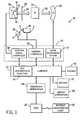
1 veranschaulicht schematisch ein exemplarisches CT-Bildgebungssystem gemäß einem Ausführungsbeispiel der vorliegenden Erfindung; 1 schematically illustrates an exemplary CT imaging system according to an embodiment of the present invention;
2 veranschaulicht ein Ausführungsbeispiel einer Röntgenröhrenvorrichtung, zu der eine Anode und eine Kathodenanordnung gehören, gemäß einem Ausführungsbeispiel der vorliegenden Erfindung; 2 Fig. 11 illustrates one embodiment of an x-ray tube apparatus including an anode and a cathode assembly according to one embodiment of the present invention;
3 veranschaulicht ein Ausführungsbeispiel einer Kathodenanordnung mit einer teilweise beschichteten thermionischen Glühwendel gemäß einem Ausführungsbeispiel der vorliegenden Erfindung; 3 FIG. 11 illustrates one embodiment of a cathode assembly having a partially coated thermionic filament in accordance with one embodiment of the present invention; FIG.
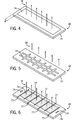
4 veranschaulicht ein Ausführungsbeispiel einer thermionischen Glühwendel mit einer Beschichtung, die rechtwinklig angebracht ist, gemäß einem Ausführungsbeispiel der vorliegenden Erfindung; 4 FIG. 12 illustrates an embodiment of a thermionic filament having a coating that is mounted at right angles, according to one embodiment of the present invention; FIG.
5 veranschaulicht ein Ausführungsbeispiel einer thermionischen Glühwendel mit einer Beschichtung, die in einem Rastermuster angebracht ist, gemäß einem Ausführungsbeispiel der vorliegenden Erfindung; 5 FIG. 12 illustrates an embodiment of a thermionic filament having a coating mounted in a raster pattern according to one embodiment of the present invention; FIG.
6 veranschaulicht ein Ausführungsbeispiel einer mit Schlitzen ausgebildeten Glühwendel mit einer Beschichtung, die rechtwinklig angebracht ist, gemäß einem Ausführungsbeispiel der vorliegenden Erfindung; 6 Fig. 12 illustrates an embodiment of a slotted filament having a coating disposed at right angles, according to one embodiment of the present invention;
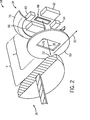
7 veranschaulicht ein Ausführungsbeispiel einer teilweise beschichteten gewickelten Glühwendel gemäß einem Ausführungsbeispiel der vorliegenden Erfindung; 7 FIG. 12 illustrates one embodiment of a partially coated wound filament according to one embodiment of the present invention; FIG.
8 veranschaulicht ein Ausführungsbeispiel eines teilweise beschichteten geradlinigen Glühdrahts gemäß einem Ausführungsbeispiel der vorliegenden Erfindung; und 8th FIG. 12 illustrates one embodiment of a partially coated rectilinear filament according to one embodiment of the present invention; FIG. and
9 veranschaulicht eine teilweise beschichtete gekrümmte Glühwendel, die für indirekte Elektronenemissionen genutzt werden kann, gemäß einem Ausführungsbeispiel der vorliegenden Erfindung. 9 illustrates a partially coated curved filament suitable for indirect Electron emissions, according to one embodiment of the present invention.
DETAILLIERTE BESCHREIBUNG DER ERFINDUNGDETAILED DESCRIPTION OF THE INVENTION
In gewissen Röntgenstrahlkathodenanordnungen können eine oder mehrere thermionische Glühwendeln verwendet werden, um einen Strom von Elektroden zu emittieren. Eine thermionische Glühwendel kann dazu veranlasst werden, durch die Anwendung von Wärmeenergie Elektronen aus der Oberfläche der Glühwendel freizugeben. In der Tat können umso mehr Elektronen emittiert werden, je heißer das Glühwendelmaterial ist. Das Glühwendelmaterial wird gewöhnlich mit Blick auf seine Fähigkeit, mittels des thermionischen Effekts Elektronen hervorzubringen, und mit Blick auf seine Fähigkeit hohen Temperaturen zu widerstehen gewählt, die in einigen Fällen oberhalb von etwa 2500°C oder darüber liegen können. Bisher wurde als Glühwendelmaterial gewöhnlich Wolfram oder ein Wolframderivat gewählt, beispielsweise dotiertes Wolfram (d. h. Wolfram mit hinzugefügten Verunreinigungen). Wolfram weist einen hohen Schmelzpunkt und eine verhältnismäßig geringe Austrittsarbeit auf (d. h. eine Maßzahl für die minimale Energie, die erforderlich ist, um zu bewirken, dass ein Elektron einen Stoff verlässt). Allerdings emittiert eine herkömmliche Wolframglühwendel bei gleicher Temperatur gewöhnlich weniger Elektronen als Ausführungsbeispiele einer beschichteten Glühwendel, wie sie hierin offenbart und erörtert sind. Daher können Röntgenröhren, die die offenbarten Ausführungsbeispiele beschichteter Glühwendeln verwenden, in der Lage sein, im Vergleich zu Röntgenröhren, die herkömmliche unbeschichtete Glühwendeln verwenden, bei gleicher Temperatur eine höhere Röntgenausgangsleistung zu erzeugen.In certain x-ray cathode arrangements, one or more thermionic filaments may be used to emit a stream of electrodes. A thermionic filament may be caused to release electrons from the surface of the filament by the application of thermal energy. In fact, the hotter the filament material, the more electrons can be emitted. The filament material is usually chosen for its ability to emit electrons by the thermionic effect, and for its ability to withstand high temperatures, which in some cases may be above about 2500 ° C or above. Heretofore, tungsten or a tungsten derivative, such as doped tungsten (i.e., tungsten with added impurities), has usually been selected as the filament material. Tungsten has a high melting point and a relatively low work function (i.e., a measure of the minimum energy required to cause an electron to leave a material). However, a conventional tungsten filament at the same temperature usually emits fewer electrons than embodiments of a coated filament as disclosed and discussed herein. Therefore, X-ray tubes using the disclosed embodiments of coated filaments may be capable of producing higher X-ray output at the same temperature as compared to X-ray tubes using conventional uncoated filaments.
Unter Beachtung des Vorausgehenden kann es von Vorteil sein, Ausführungsbeispiele von Bildgebungssystemen, die die hierin beschriebenen beschichteten Glühwendeln nutzen können, zu erörtern, bevor diese Offenbarungen im Einzelnen erörtert werden. Während dies berücksichtigt wird und nun auf die Figuren eingegangen wird, veranschaulicht 1 schematisch ein Bildgebungssystem 10 zum Akquirieren und Verarbeiten von Bilddaten. In dem veranschaulichten Ausführungsbeispiel ist das System 10 ein Computertomographie-(CT)-System, das dazu eingerichtet ist, Röntgenprojektionsdaten zu akquirieren, um die Projektionsdaten in ein tomographisches Bild zu überführen, und um die Bilddaten zu verarbeiten, um sie visuell wiederzugeben und zu analysieren. Obwohl das Bildgebungssystem 10 in Zusammenhang mit medizinischer Bildgebung erörtert ist, lassen sich die hier erörterten Techniken und Konfigurationen in sonstigen nicht invasiven medizinischen Bildgebungsanwendungen nutzen, z. B. für die Durchleuchtung von Gepäck oder Paketen, oder für eine industrielle zerstörungsfreie Analyse fertiger Teile. In dem in 1 veranschaulichten Ausführungsbeispiel enthält das CT-Bildgebungssystem 10 eine Röntgenstrahlenquelle 12. Wie hierin im Einzelnen erörtert, kann die Quelle 12 auf einer oder mehreren herkömmlichen Röntgenstrahlenquellen basieren, z. B. auf einer Röntgenröhre. Beispielsweise kann die Quelle 12 auf einer Röntgenröhre mit einer Kathodenanordnung 14 und einer Anode 16 basieren, wie weiter unten mit Bezug auf 2 näher erläutert. Die Kathodenanordnung 14 kann einen Strom von Elektronen 18 (d. h. den Elektronenstrahl), von denen einige auf die Targetanode 16 auftreffen, beschleunigen. Der auf die Anode 16 einfallende Elektronenstrahl 18 bewirkt die Aussendung eines Röntgenstrahls 20.With the foregoing in mind, it may be advantageous to discuss embodiments of imaging systems that may utilize the coated filaments described herein before discussing these disclosures in detail. While this is taken into account and will now be dealt with the figures, illustrated 1 schematically an imaging system 10 for acquiring and processing image data. In the illustrated embodiment, the system is 10 a computed tomography (CT) system adapted to acquire x-ray projection data to convert the projection data into a tomographic image and to process the image data to visually render and analyze it. Although the imaging system 10 In the context of medical imaging, the techniques and configurations discussed herein may be used in other non-invasive medical imaging applications, e.g. B. for the screening of luggage or packages, or for an industrial non-destructive analysis of finished parts. In the in 1 illustrated embodiment includes the CT imaging system 10 an x-ray source 12 , As discussed in detail herein, the source 12 based on one or more conventional X-ray sources, e.g. B. on an x-ray tube. For example, the source 12 on an x-ray tube with a cathode arrangement 14 and an anode 16 based as below with respect to 2 explained in more detail. The cathode arrangement 14 can be a stream of electrons 18 (ie the electron beam), some of which target the anode 16 hit, accelerate. The one on the anode 16 incident electron beam 18 causes the emission of an X-ray 20 ,
Die Quelle 12 kann in unmittelbarer Nachbarschaft eines Kollimators 22 positioniert sein. Der Kollimator 22 kann für jeden Emissionspunkt der Quelle 12 eine oder mehrerer Kollimierungsbereiche, z. B. Blei- oder Wolframverschlüsse, umfassen. Der Kollimator 22 definiert gewöhnlich die Größe und Gestalt des einen oder der mehreren Röntgenstrahlen 20, die in einen Bereich hineinstrahlen, in dem eine Person 24 oder ein Objekt angeordnet ist. Jeder Röntgenstrahl 20 kann in Abhängigkeit von der Konstruktion der Detektormatrix und/oder des gewünschten Verfahrens der Datenakquisition im Wesentlichen fächerförmig oder konusförmig sein. Ein geschwächter Anteil 26 jedes Röntgenstrahls gelangt durch die Person oder das Objekt 20 hindurch und fällt auf eine Detektormatrix ein, die allgemein mit dem Bezugszeichen 28 bezeichnet ist.The source 12 can be in the immediate vicinity of a collimator 22 be positioned. The collimator 22 can be for each emission point of the source 12 one or more collimation areas, e.g. As lead or tungsten closures include. The collimator 22 usually defines the size and shape of the one or more x-rays 20 that radiate into an area in which a person 24 or an object is arranged. Every x-ray 20 may be substantially fan-shaped or conical, depending on the design of the detector array and / or the desired method of data acquisition. A weakened share 26 Each X-ray passes through the person or object 20 and falls on a detector matrix, generally designated by the reference numeral 28 is designated.
Der Detektor 28 wird im Allgemeinen durch eine Anzahl von Detektorelementen gebildet, die die Röntgenstrahlen 20 erfassen, nachdem sie eine im Blickfeld des Bildgebungssystems 10 angeordnete Person bzw. ein Objekt durchstrahlt haben oder daran vorbei gelangt sind. Jedes Detektorelement erzeugt ein elektrisches Signal, das die Intensität des Röntgenstrahls kennzeichnet, die an der Stelle des Detektorelements einfällt, wenn der Strahl auf den Detektor 28 trifft. Elektrische Signale werden akquiriert und verarbeitet, um eine oder mehrere Scandatensätze zu erzeugen.The detector 28 is generally formed by a number of detector elements containing the x-rays 20 capture, having one in the field of vision of the imaging system 10 arranged person or have passed through an object or have passed it. Each detector element generates an electrical signal indicative of the intensity of the x-ray beam incident at the location of the detector element when the beam is incident on the detector 28 meets. Electrical signals are acquired and processed to generate one or more scan records.
Ein Systemcontroller 30 steuert den Betrieb des Bildgebungssystems 10, um Untersuchungs- und/oder Kalibrierungsprotokolle auszuführen, und um die akquirierten Daten zu verarbeiten. Die Quelle 12 wird gewöhnlich durch einen Systemcontroller 30 geregelt/gesteuert. Allgemein stellt der Systemcontroller 30 für die Röntgenuntersuchungssequenzen Leistung, Brennfleckort, Steuersignale und so fort bereit. Der Detektor 28 ist mit dem Systemcontroller 30 verbunden, der die Akquisition der Signale steuert, die durch den Detektor 28 erzeugt werden. Der Systemcontroller 30 kann außerdem vielfältige Signalverarbeitungs- und Filterfunktionen ausführen, z. B. eine anfängliche Einstellung von Dynamikbereichen, eine Verschachtelung digitaler Bilddaten, und so fort. Im vorliegenden Zusammenhang kann der Systemcontroller 30 ferner Signalverarbeitungsschaltkreise und zugeordnete Speicherschaltungen enthalten. Wie nachfolgend eingehender beschrieben, können die zugehörigen Speicherschaltungen Programme, durch den Systemcontroller 30 ausgeführte Programmroutinen und/oder kodierte Algorithmen, Konfigurationsparameter, Bilddaten, und so fort speichern. In einem Ausführungsbeispiel kann der Systemcontroller 30 ganz oder teilweise als ein prozessorgestütztes System, beispielsweise ein Universal- oder ein anwendungsspezifisches Computersystem, verwirklicht sein.A system controller 30 controls the operation of the imaging system 10 to perform examination and / or calibration protocols and to process the acquired data. The source 12 is usually done by a system controller 30 regulated / controlled. General notes the system controller 30 for the X-ray examination sequences power, focal spot, control signals and so forth ready. The detector 28 is with the system controller 30 connected, which controls the acquisition of the signals by the detector 28 generated become. The system controller 30 can also perform a variety of signal processing and filtering functions, e.g. For example, an initial adjustment of dynamic ranges, interleaving digital image data, and so on. In the present context, the system controller 30 further include signal processing circuitry and associated memory circuits. As described in more detail below, the associated memory circuits may be programs, by the system controller 30 execute executed program routines and / or coded algorithms, configuration parameters, image data, and so on. In one embodiment, the system controller 30 in whole or in part as a processor-based system, such as a general-purpose or application-specific computer system.
In dem in 1 veranschaulichten Ausführungsbeispiel kann der Systemcontroller 30 die Bewegung eines Linearpositionierungssubsystem 32 und eines Rotationssubsystems 34 mittels eines Antriebscontrollers 36 regeln/steuern. In einem Ausführungsbeispiel, in dem das Bildgebungssystem 10 eine Rotation der Quelle 12 und/oder des Detektors 28 aufweist, kann das Rotationssubsystem 34 die Quelle 12, denn Kollimator 22 und/oder den Detektor 28 um die Person 24 rotieren lassen. Es ist zu beachten, dass das Rotationssubsystem 34 eine Gantry enthalten kann, die sowohl stationäre Komponenten (einen Stator) und rotierende Komponenten (einen Rotor) aufweist.In the in 1 illustrated embodiment, the system controller 30 the movement of a linear positioning subsystem 32 and a rotation subsystem 34 by means of a drive controller 36 regulate / control. In an embodiment in which the imaging system 10 a rotation of the source 12 and / or the detector 28 can, the rotation subsystem 34 the source 12 , because collimator 22 and / or the detector 28 around the person 24 rotate. It should be noted that the rotation subsystem 34 may include a gantry having both stationary components (a stator) and rotating components (a rotor).
Das Linearpositionierungssubsystem 32 kann einen Tisch oder Träger, auf dem die einer Bildgebung unterworfene Person bzw. das Objekt angeordnet ist, linear verschieben. Somit kann der Tisch oder Träger in der Gantry oder in einem Bildgebungsvolumen (z. B. in dem Volumen, das zwischen der Quelle 12 und dem Detektor 28 angeordnet ist) linear bewegt werden und die Akquisition von Daten aus speziellen Bereichen des Patienten oder des Objekts, und somit die Erzeugung von Bildern ermöglichen, die jenen speziellen Bereichen zugeordnet sind. Darüber hinaus kann das Linearpositionierungssubsystem 32 eine oder mehrere Komponenten des Kollimators 22 verschieben, um die Form und/oder Richtung des Röntgenstrahls 20 einzustellen. Darüber hinaus kann in Ausführungsbeispielen, bei denen die Quelle 12 und der Detektor 28 dazu eingerichtet sind, einen weiten oder ausreichenden Überstreichungsbereich längs der z-Achse (d. h. der Achse, die im Wesentlichen der Länge des Patiententisches oder -trägers und/oder der Längsrichtung des Bildgebungstunnels zugeordnet ist) vorzusehen, und/oder bei denen die lineare Bewegung des Patienten oder Objekts nicht erforderlich ist, auf das Linearpositionierungssubsystem 32 verzichtet werden.The linear positioning subsystem 32 may linearly move a table or support on which the subject or object is placed. Thus, the table or support may be in the gantry or in an imaging volume (eg, in the volume that is between the source 12 and the detector 28 is arranged) to move linearly and allow the acquisition of data from particular areas of the patient or object, and thus the generation of images associated with those particular areas. In addition, the linear positioning subsystem 32 one or more components of the collimator 22 shift to the shape and / or direction of the x-ray beam 20 adjust. In addition, in embodiments where the source 12 and the detector 28 are adapted to provide a wide or sufficient swept area along the z-axis (ie, the axis substantially corresponding to the length of the patient table or support and / or the longitudinal direction of the imaging tunnel), and / or where the linear motion of the Patient or object is not required on the linear positioning subsystem 32 be waived.
Wie dem Fachmann einleuchten wird, kann die Quelle 12 durch einen Röntgenstrahlcontroller 38 geregelt/gesteuert werden, der in dem Systemcontroller 30 angeordnet ist. Der Röntgenstrahlcontroller 38 kann dazu eingerichtet sein, an die Quelle 12 Leistungs- und Zeittaktsignale auszugeben. Darüber hinaus kann der Röntgenstrahlcontroller 30 in einigen Ausführungsbeispielen dazu eingerichtet sein, die Quelle 12 selektiv zu aktivieren, so dass Röhren oder Emitter an unterschiedlichen Orten innerhalb des Systems 10 miteinander synchron oder voneinander unabhängig betrieben werden können.As will be apparent to those skilled in the art, the source may be 12 through an X-ray controller 38 be controlled / controlled in the system controller 30 is arranged. The X-ray controller 38 can be set up to the source 12 Output power and timing signals. In addition, the X-ray controller can 30 in some embodiments, be adapted to the source 12 to activate selectively, leaving tubes or emitters at different locations within the system 10 can be operated synchronously or independently of each other.
Darüber hinaus kann der Systemcontroller 30 ein Datenakquisitionssystem (DAS) 40 aufweisen. In einem Ausführungsbeispiel ist der Detektor 28 mit dem Systemcontroller 30 und spezieller mit dem Datenakquisitionssystem 40 verbunden. Das Datenakquisitionssystem 40 nimmt Daten auf, die durch eine Ausleseelektronik des Detektors 28 gesammelt sind. Das Datenakquisitionssystem 40 nimmt gewöhnlich abgetastete analoge Signale von dem Detektor 28 auf und wandelt die Daten in digitale Signale um, um diese anschließend durch ein prozessorgestütztes System, beispielsweise durch einen Computer 42, zu verarbeiten. In einer Abwandlung kann der Detektor 28 in anderen Ausführungsbeispielen die abgetasteten analogen Signale vor einer Übermittlung an das Datenakquisitionssystem 40 in digitale Signale umwandeln.In addition, the system controller 30 a data acquisition system (DAS) 40 exhibit. In one embodiment, the detector is 28 with the system controller 30 and more specifically with the data acquisition system 40 connected. The data acquisition system 40 picks up data by a readout electronics of the detector 28 are collected. The data acquisition system 40 usually picks up sampled analog signals from the detector 28 and converts the data into digital signals, then through a processor-based system, such as a computer 42 , to process. In a modification, the detector may 28 in other embodiments, the sampled analog signals prior to transmission to the data acquisition system 40 convert to digital signals.
In dem dargestellten Ausführungsbeispiel ist ein Computer 42 mit dem Systemcontroller 30 verbunden. Die durch das Datenakquisitionssystem 40 gesammelten Daten können für eine anschließende Verarbeitung an den Computer 42 übermittelt werden. Beispielsweise kann an den von dem Detektor 28 gesammelten Daten in dem Datenakquisitionssystem 40 und/oder in dem Computer 42 eine Vorverarbeitung und Kalibrierung vorgenommen werden, um Darstellungen der Linienintegrale der Schwächungskoeffizienten des einer Bildgebung unterworfenen Patienten oder Objekts hervorzubringen. In einem Ausführungsbeispiel enthält der Computer 42 Datenverarbeitungsschaltkreise 44, die dazu dienen, die von dem Detektor 28 gesammelten Daten zu filtern und zu verarbeiten.In the illustrated embodiment is a computer 42 with the system controller 30 connected. The data acquisition system 40 Collected data can be sent to the computer for subsequent processing 42 be transmitted. For example, to that of the detector 28 collected data in the data acquisition system 40 and / or in the computer 42 preprocessing and calibration are performed to produce representations of the line integrals of the attenuation coefficients of the patient or object being imaged. In one embodiment, the computer includes 42 Data processing circuits 44 that are used by the detector 28 to filter and process collected data.
Der Computer 42 kann einen Speicher 46 enthalten oder mit einem solchen Daten austauschen, der in der Lage ist, durch den Computer 42 bereits verarbeitete Daten, durch den Computer 42 noch zu verarbeitende Daten oder durch den Computer 42 auszuführende Programmroutinen und/oder Algorithmen zu speichern. Es ist selbstverständlich, dass das Bildgebungssystem 10 beliebige rechnerzugänglicher Speichereinrichtungen verwenden kann, die in der Lage sind, die gewünscht Menge oder Art von Daten und/oder Programmcode zu speichern. Darüber hinaus kann der Speicher 46 auf einer oder mehreren Speichereinrichtungen, z. B. magnetischen, Halbleiter- oder optischen Vorrichtungen ähnlichen oder unterschiedlichen Typs basieren, die in Bezug auf das System 10 ortsnah und/oder entfernt angeordnet sein können.The computer 42 can a memory 46 contain or exchange with any such data that is capable of through the computer 42 already processed data, by the computer 42 data still to be processed or by the computer 42 to save executing program routines and / or algorithms. It goes without saying that the imaging system 10 may use any computer-accessible storage device capable of storing the desired amount or type of data and / or program code. In addition, the memory can 46 on one or more storage devices, e.g. Magnetic, semiconductor or optical devices of similar or different types based on the system 10 can be arranged close to the place and / or remotely.
Der Computer 42 kann außerdem dazu eingerichtet sein, Merkmale zu steuern, die durch den Systemcontroller 30 aktiviert werden (z. B. Scanvorgänge und Datenakquisition). Außerdem kann der Computer 42 dazu eingerichtet sein, von einem Anwender Steuerbefehle und Scanparameter über eine Bedienungsworkstation 48 aufzunehmen, die mit einer Tastatur und/oder sonstigen Eingabegeräten ausgerüstet sein kann. Ein Bediener kann dadurch das System 10 über die Bedienungsworkstation 48 steuern. Somit kann der Bediener ein von dem Computer 42 rekonstruiertes Bild und/oder sonstige für das System 10 maßgebende Daten beobachten. Desgleichen kann die Bedienperson über die Bedienungsworkstation 48 Bildgebungs- oder Kalibrierungsprogrammroutinen starten, Bildfilter auswählen und anwenden, und so fort.The computer 42 may also be configured to control features provided by the system controller 30 be activated (eg, scans and data acquisition). Besides, the computer can 42 be configured to receive control commands and scan parameters from a user via an operator workstation 48 which may be equipped with a keyboard and / or other input devices. An operator can thereby use the system 10 via the operating workstation 48 Taxes. Thus, the operator can get one from the computer 42 reconstructed image and / or other for the system 10 observe authoritative data. Likewise, the operator can use the operating workstation 48 Start imaging or calibration routines, select and apply image filters, and so on.
Wie zu sehen, kann das System 10 ferner eine Anzeigevorrichtung 50 aufweisen, die mit der Bedienungsworkstation 48 verbunden ist. Darüber hinaus kann das System 10 einen Drucker 52 enthalten, der mit der Bedienungsworkstation 48 verbunden ist, und der dazu eingerichtet ist, solche Spannungsmessergebnisse auszudrucken. Die Anzeigevorrichtung 50 und der Drucker 52 können ferner unmittelbar oder über die Bedienungsworkstation 48 mit dem Computer 42 verbunden sein. Darüber hinaus kann die Bedienungsworkstation 48 ein Bildarchivierungs- und Datenkommunikationssystem (PACS) 54 aufweisen oder damit verbunden sein. Es ist zu beachten, dass das PACS 54 mit einem entfernt angeordneten System 56, einem Informationssystem einer radiologischen Abteilung (RIS, Radiology Department Information System), einem klinischen Datenkommunikationssystem (HIS, Hospital Information System) oder einem internen oder externen Netzwerk verbunden sein kann, so dass weitere Personen an unterschiedlichen Orten auf die Bilddaten zugreifen können.As you can see, the system can 10 a display device 50 that communicate with the operating workstation 48 connected is. In addition, the system can 10 a printer 52 included with the control workstation 48 connected, and which is adapted to print such voltage measurement results. The display device 50 and the printer 52 can also directly or via the Bedienungsworkstation 48 with the computer 42 be connected. In addition, the operating workstation 48 a picture archiving and data communication system (PACS) 54 have or be connected. It should be noted that the PACS 54 with a remote system 56 , a Radiology Department Information System (RIS) information system, a Hospital Information System (HIS), or an internal or external network, so that others can access the image data at different locations.
Unter Berücksichtigung der vorausgehenden allgemeinen Systembeschreibung wird nun auf 2 eingegangen, in der ein Ausführungsbeispiel einer Röntgenröhrenvorrichtung 58 veranschaulicht ist, die Ausführungsbeispiele der Kathodenanordnung 14 und der Anode 16 enthält, wie sie in 1 gezeigt sind. In dem veranschaulichten Ausführungsbeispiel sind die Kathodenanordnung 14 und die Targetanode 16 mit einem Kathodentargetabstand d voneinander beabstandet angeordnet und gegeneinander ausgerichtet. Die Kathodenanordnung 14 kann einen Satz von Vorspannungselektroden (d. h. Ablenkelektroden) 60, 62, 64, 66, eine Glühwendel 68, eine Absaugelektrode 69 und eine Abschirmung 70 enthalten, die mit Bezug auf 3 weiter unten näher erläutert ist. Die Anode 16 kann aus einem beliebigen geeigneten Metall oder Verbundstoff hergestellt sein, beispielsweise Wolfram, Molybdän oder Kupfer. Das Oberflächenmaterial der Anode ist gewöhnlich mit Blick auf eine verhältnismäßig hohe Wärmebeständigkeit ausgewählt, um der Temperatur standzuhalten, die durch die auf die Anode 16 auftreffenden Elektronen entsteht. In speziellen Ausführungsbeispielen kann die Anode 16, wie veranschaulicht, eine rotierende Scheibe sein. Dementsprechend kann die Anode 16 mit einer hohen Drehzahl (z. B. 1.000 bis 10.000 Umdrehungen pro Minute) gedreht werden, um die einfallende Wärmeenergie zu verteilen und um eine höhere Temperaturtoleranz zu erreichen. Die Rotation der Anode 16 führt dazu, dass die Temperatur des Brennflecks 72 (d. h. der Stelle auf der Anode, auf der die Elektronen auftreffen) bei einem tieferen Wert gehalten wird, als der Fall wäre, wenn die Anode 16 nicht gedreht wird, so dass dadurch die Nutzung von Ausführungsbeispielen mit Hochflussröntgenstrahlen gestattet ist.Taking into account the preceding general system description is now on 2 in which an embodiment of an X-ray tube device 58 is illustrated, the embodiments of the cathode assembly 14 and the anode 16 contains, as in 1 are shown. In the illustrated embodiment, the cathode assembly is 14 and the target anode 16 arranged at a cathode distance d spaced from each other and aligned with each other. The cathode arrangement 14 may include a set of bias electrodes (ie deflection electrodes) 60 . 62 . 64 . 66 , a filament 68 , a suction electrode 69 and a shield 70 included with respect to 3 is explained in more detail below. The anode 16 may be made of any suitable metal or composite, for example tungsten, molybdenum or copper. The surface material of the anode is usually selected for a relatively high heat resistance to withstand the temperature passing through the anode 16 impinging electrons arises. In specific embodiments, the anode 16 as illustrated, be a rotating disk. Accordingly, the anode 16 be rotated at a high speed (eg, 1,000 to 10,000 revolutions per minute) to distribute the incident heat energy and to achieve a higher temperature tolerance. The rotation of the anode 16 causes the temperature of the focal spot 72 (ie, the location on the anode where the electrons strike) is kept at a lower value than would be the case when the anode 16 is not rotated, thereby allowing the use of embodiments with high-flux X-rays.
Die Kathodenanordnung 14, d. h. die Elektronenquelle, ist mit einem Kathodentargetabstand d von der Anode 16 beabstandet angeordnet, so dass der durch die Kathodenanordnung 14 erzeugte Elektronenstrahl 18 in einen Brennfleck 72 auf der Anode 16 fokussiert wird. Der Raum zwischen der Kathodenanordnung 14 und der Anode 16 ist gewöhnlich evakuiert, um Zusammenstöße von Elektronen mit anderen Atomen zu minimieren, und um ein elektrisches Potential zu maximieren. Zwischen der Kathode 14 und der Anode 16 wird gewöhnlich ein starkes, in einigen Fällen über 20 kV betragendes elektrisches Potential erzeugt, das bewirkt, dass Elektronen, die durch die Kathode 14 aufgrund des thermionischen Effekts emittiert sind, von der Anode 16 stark angezogen werden. Der sich ergebende Elektronenstrahl 18 ist in Richtung der Anode 16 gerichtet. Der sich ergebende Elektronenbeschuss des Brennflecks 72 erzeugt dann aufgrund des Bremsstrahlungseffekts, d. h. des Abbremsens der Strahlung, einen Röntgenstrahl 20.The cathode arrangement 14 , ie the electron source, is at a cathode target distance d from the anode 16 arranged spaced so that through the cathode assembly 14 generated electron beam 18 in a focal spot 72 on the anode 16 is focused. The space between the cathode assembly 14 and the anode 16 is usually evacuated to minimize collisions of electrons with other atoms and to maximize electrical potential. Between the cathode 14 and the anode 16 Typically, a strong electrical potential, in some cases greater than 20 kV, is generated which causes electrons to pass through the cathode 14 due to the thermionic effect emitted by the anode 16 be strongly attracted. The resulting electron beam 18 is in the direction of the anode 16 directed. The resulting electron bombardment of the focal spot 72 then generates an X-ray due to the Bremsstrahlung effect, ie the deceleration of the radiation 20 ,
Der Abstand d ist ein Faktor bei der Bestimmung der Eigenschaften des Brennflecks 72, beispielsweise seiner Länge und Breite, und somit auch der Bildgebungsfähigkeiten des erzeugten Röntgenstrahls 20. Falls der Abstand d zu groß ist, wird eine zu geringe Anzahl von Elektronen auf die Anode 16 einfallen, und/oder der Elektronenstrahl 18 wird zu stark streuen, um einen geeignet bemessenen Röntgenstrahl 20 zu erzeugen. Die sich ergebenden Röntgenbilder können Unschärfen oder andere Bildgebungsartefakte aufweisen. Herkömmlich wurde der Abstand d bisher mit weniger als etwa 50 mm bemessen, um einen kleinen Brennfleck (von z. B. weniger als etwa 0,25 mm2 oder kleiner) zu definieren, der in der Lage ist, einen geeigneten Röntgenstrahl 20 zu erzeugen. Die hierin beschriebenen und weiter unten mit Bezug auf die Figuren detaillierter erörterten Ausführungsbeispiele erlauben es, den Abstand d mit etwa 50 mm oder größer zu bemessen. In der Tat ermöglichen die offenbarten Ausführungsbeispiele sehr kleine Brennfleckabmessungen bei größeren Kathodentargetabständen und ermöglichen somit die Unterbringung weiterer Vorrichtungen, z. B. eines Elektronenkollektors oder von Strahllenkmagneten, in der Röntgenröhrenvorrichtung 58.The distance d is a factor in determining the characteristics of the focal spot 72 , For example, its length and width, and thus also the imaging capabilities of the generated X-ray 20 , If the distance d is too large, too few electrons will be applied to the anode 16 come in, and / or the electron beam 18 will scatter too much to get a suitably sized x-ray beam 20 to create. The resulting x-ray images may include blurring or other imaging artifacts. Conventionally, the distance d previously calculated with less than about 50 mm, to define a small focal spot (of z., Less than about 0.25 mm 2 or less), which is capable of a suitable X-ray 20 to produce. The embodiments described herein and discussed in more detail below with reference to the figures allow the distance d to be sized at about 50 mm or greater. In fact, the disclosed embodiments allow for very small focal spot dimensions at larger cathode target spacings, thus enabling the placement of other devices, e.g. As an electron collector or of Strahllenkmagneten, in the X-ray tube apparatus 58 ,
In speziellen Ausführungsbeispielen ist die Absaugelektrode 69 enthalten, und sie ist zwischen der Kathodenanordnung 14 und der Anode 16 angeordnet. In weiteren Ausführungsbeispielen ist die Absaugelektrode 69 nicht enthalten. Falls die Absaugelektrode enthalten ist, kann sie auf dem Potential der Anode 16 gehalten sein, das in manchen Fällen 20 kV überschreitet. Die Absaugelektrode 69 weist eine Öffnung 71 auf. Die Öffnung 71 gestattet es Elektronen, die Absaugelektrode 69 zu durchqueren. In dem dargestellten Ausführungsbeispiel ist die Absaugelektrode mit einem Kathodenelektrodenabstand e von der Kathodenanordnung 14 beabstandet angeordnet. Der Kathodenelektrodenabstand e ist ebenfalls ein Faktor bei der Bestimmung der Eigenschaften des Brennflecks 72, beispielsweise der Länge und Breite, und somit der Bildgebungsfähigkeiten des erzeugten Röntgenstrahls 20. Die Elektronen werden über die Strecke e beschleunigt und bewegen sich über die Strecke d–e ohne Beschleunigung. Falls der Abstand e zu groß ist, wird eine unzureichende Anzahl von Elektronen auf die Anode 16 einfallen, und/oder der Elektronenstrahl 18 kann zu sehr streuen, um einen geeignet bemessenen Röntgenstrahl 20 zu erzeugen. Die sich ergebenden Röntgenbilder können Unschärfen oder andere Bildgebungsartefakte aufweisen. Herkömmlich wurde der Abstand e bisher mit weniger als etwa 50 mm bemessen, um einen kleinen Brennfleck (z. B. kleiner als etwa 0,25 mm2 oder kleiner) zu bilden, der in der Lage ist, einen angemessenen Röntgenstrahl 20 zu erzeugen. Die hierin beschriebenen und weiter unten mit Bezug auf die Figuren detaillierter erörterten Ausführungsbeispiele erlauben es, den Abstand e mit etwa 15 mm bis über 50 mm zu bemessen.In specific embodiments, the suction electrode is 69 included, and it is between the cathode assembly 14 and the anode 16 arranged. In further embodiments, the suction electrode 69 not included. If the suction electrode is included, it can be at the potential of the anode 16 be kept, which in some cases exceeds 20 kV. The suction electrode 69 has an opening 71 on. The opening 71 it allows electrons, the suction electrode 69 to cross. In the illustrated embodiment, the suction electrode is at a cathode electrode distance e from the cathode assembly 14 spaced apart. The cathode electrode distance e is also a factor in determining the characteristics of the focal spot 72 For example, the length and width, and thus the imaging capabilities of the generated X-ray beam 20 , The electrons are accelerated over the distance e and move over the distance d-e without acceleration. If the distance e is too large, an insufficient number of electrons will be applied to the anode 16 come in, and / or the electron beam 18 can scatter too much to get a suitably sized x-ray beam 20 to create. The resulting x-ray images may include blurring or other imaging artifacts. Conventionally, the distance e has heretofore been sized to be less than about 50 mm to form a small focal spot (e.g., less than about 0.25 mm 2 or smaller) capable of producing an adequate x-ray beam 20 to create. The embodiments described herein and discussed in greater detail below with reference to the figures allow the distance e to be sized at about 15 mm to over 50 mm.
Mit Bezug auf 3 ist ein Ausführungsbeispiel einer Röntgenstrahlkathodenanordnung 14 veranschaulicht, bei dem die Glühwendel 68 eine beschichtete ebene thermionische Glühwendel ist. In dem veranschaulichten Ausführungsbeispiel weist die Glühwendel 68 eine Beschichtung 74 auf, die auf ein Substrat 76 aufgebracht ist. In speziellen Ausführungsbeispielen kann die Beschichtung 74 auf Materialien wie Hafniumkarbid, Tantalkarbid, Hafniumdiborid, Zirkoniumkarbid, Hafniumnitrid, Tantalnitrid, Zirkoniumnitrid, Wolframdiborid und deren Derivate basieren, und auf das Substrat 76, wie nachfolgend mit Bezug auf 4–6 näher erläutert, aufgetragen sein. Das Substrat 76 kann in Form einer Scheibe oder eines Rechtecks aus einem Material wie Wolfram oder Tantal hergestellt sein. Es versteht sich, dass das Substrat 76 andere Formen aufweisen kann, beispielsweise auf einem Draht, einem gewickelten Draht, einer gekrümmten Scheibe, einer ebenen Scheibe, und so fort, basieren kann.Regarding 3 is an embodiment of an X-ray cathode assembly 14 illustrates where the filament 68 a coated plane thermionic filament is. In the illustrated embodiment, the filament has 68 a coating 74 on that on a substrate 76 is applied. In specific embodiments, the coating 74 based on materials such as hafnium carbide, tantalum carbide, hafnium diboride, zirconium carbide, hafnium nitride, tantalum nitride, zirconium nitride, tungsten diboride and their derivatives, and on the substrate 76 as below with reference to 4 - 6 be explained in more detail, be applied. The substrate 76 may be made in the form of a disk or a rectangle of a material such as tungsten or tantalum. It is understood that the substrate 76 may have other shapes, for example, based on a wire, a wound wire, a curved disk, a flat disk, and so forth.
Es kann eine Beschichtung 74 ausgewählt werden, die eine geringere Austrittsarbeit als diejenige des Substrats 76 aufweist. D. h., die für die Freigabe von Elektronen der Beschichtung 74 erforderliche thermische Energie kann geringer sein, als diejenige, die für das Substrat 76 vorausgesetzt ist. In Ausführungsbeispielen von Glühwendeln, bei denen die Beschichtung eine Austrittsarbeit von etwa 3,5 Elektronenvolt (eV) aufweist, kann die Stromdichte emittierter Elektronen (d. h. eine Maßzahl, die die Anzahl und Dichte von Elektronen kennzeichnet, die pro Flächenbereich der Glühwendel emittiert werden) im Vergleich zu einer herkömmlichen unbeschichteten Wolframglühwendel bei derselben Temperatur in der Tat um einen Faktor von etwa Hundert besser sein. Die beschichtete Glühwendel 68 kann also im Vergleich zu dem durch eine herkömmliche Glühwendel erzeugten Elektronenstrahl bei derselben Temperatur erheblich mehr Elektronen und einen stärkeren Elektronenstrahl 18 hervorbringen. Eine Beschichtung, die eine Austrittsarbeit von weniger als etwa 4,5 eV aufweist, kann in der Tat eine Glühwendel 68 ergeben, die im Vergleich zu dem durch eine herkömmliche Glühwendel erzeugten Elektronenstrahl bei derselben Temperatur einen stärkeren Elektronenstrahl 18 erzeugt. Darüber hinaus kann die Beschichtung 74 ausgewählt werden, um gegenüber gewissen, möglicherweise in der Röntgenröhrenvorrichtung 58 vorhandenen Gasen, sowie gegenüber Beschuss durch zurückprallende Ionen (z. B. abprallende Elektronen) beständig zu sein, was eine Beschichtung 74 ergibt, die eine lange Betriebslebensdauer aufweist.It can be a coating 74 which has a lower work function than that of the substrate 76 having. That is, for the release of electrons of the coating 74 required thermal energy may be less than that for the substrate 76 is required. In exemplary embodiments of incandescent filaments in which the coating has a workfunction of about 3.5 electron volts (eV), the current density of emitted electrons (ie a measure indicating the number and density of electrons emitted per area of the filament) in the In fact, compared to a conventional uncoated tungsten filament filament at the same temperature, it may be better by a factor of about one hundred. The coated filament 68 Thus, compared to the electron beam generated by a conventional filament at the same temperature significantly more electrons and a stronger electron beam 18 bring forth. A coating having a work function of less than about 4.5 eV may indeed be an incandescent filament 68 result in a stronger electron beam at the same temperature as compared to the electron beam generated by a conventional filament 18 generated. In addition, the coating can 74 be selected to match certain, possibly in the x-ray tube device 58 existing gases, as well as against bombardment by rebounding ions (eg rebounding electrons) to be resistant, which is a coating 74 results, which has a long service life.
Weiter kann die thermionische Temperatur der Glühwendel 68 (d. h. die Temperatur, bei der Elektronenemissionen auftreten) geregelt werden, so dass die Beschichtung 74, und nicht das Substrat 76, als die primäre Emissionsschicht des Elektronenstrahls 18 wirken kann. Eine Beschichtung 74, die eine geringere Austrittsarbeit aufweist, wird Elektronen bei einer niedrigeren Temperatur emittieren als ein Substrat mit einer höheren Austrittsarbeit. Dementsprechend kann die Temperatur der Glühwendel 68 bei einem Wert eingestellt werden, der beispielsweise um 400°C niedriger ist als der für eine herkömmliche Glühwendel vorgegebene Wert. Aufgrund der geringeren Austrittsarbeit der Beschichtung 74 wird diese bei der geringeren Temperatur Elektronen ausstrahlen. Ein Verwenden niedrigerer Betriebstemperaturen kann außerdem mit Blick auf eine Verlängerung der Lebensdauer der beschichteten Glühwendel 68 vorteilhaft sein. Ein Ausfall der Glühwendel 68 wird bisher gewöhnlich aufgrund von Verdampfung des Materials der Glühwendel 68 während des thermionischen Betriebs beschleunigt. Unter Hochvakuumbedingungen, wie sie beispielsweise innerhalb der Röntgenröhrenvorrichtung 58 vorliegen, kann ein Materialverlust proportional zu dem Dampfdruck des verdampfenden Materials sein. Der Dampfdruck der Ausführungsbeispiele, die die Beschichtung 74 verwenden, beispielsweise Beschichtungen 74, die auf Hafniumkarbid, Tantalkarbid, Hafniumdiborid, Zirkoniumkarbid, Hafniumnitrid, Tantalnitrid, Zirkoniumnitrid und/oder Wolframdiborid basieren, kann in manchen Fällen bei derselben thermionischen Emissionsdichte sechs mal geringer sein als derjenige herkömmlicher Wolframglühwendeln. Somit kann die Lebensdauer der beschichteten Glühwendel 68 beträchtlich gesteigert werden, da die Glühwendel 68 eine geringere Materialverdampfung aufweisen kann.Next, the thermionic temperature of the filament 68 (ie the temperature at which electron emissions occur), so that the coating 74 , and not the substrate 76 , as the primary emission layer of the electron beam 18 can work. A coating 74 having a lower work function will emit electrons at a lower temperature than a substrate having a higher work function. Accordingly, the temperature of the filament 68 be set at a value, for example, is lower by 400 ° C than the predetermined value for a conventional filament. Due to the lower work function of the coating 74 this will emit electrons at the lower temperature. Using lower operating temperatures may also be considered with a view to extending the life of the coated filament 68 be beneficial. A failure of filament 68 is usually due to evaporation of the material of the filament 68 accelerated during thermionic operation. Under high vacuum conditions, such as within the x-ray tube apparatus 58 may be a material loss proportional to the vapor pressure of the evaporating material. The vapor pressure of the embodiments showing the coating 74 use, for example, coatings 74 based on hafnium carbide, tantalum carbide, hafnium diboride, zirconium carbide, hafnium nitride, tantalum nitride, zirconium nitride and / or tungsten diboride may in some cases be six times lower than that of conventional tungsten filaments at the same thermionic emission density. Thus, the life of the coated filament 68 be increased considerably, since the filament 68 may have a lower material evaporation.
Ein weiterer Vorteil einer Nutzung chemischer Stoffe wie Hafniumkarbid, Tantalkarbid, Hafniumdiborid, Zirkoniumkarbid, Hafniumnitrid, Tantalnitrid, Zirkoniumnitrid, Wolframdiborid und deren Derivate, basiert darauf, dass die sich ergebende Beschichtung 74, nachdem sie an dem Substrat 76 angebracht ist, sehr stabil sein kann. D. h., die Glühwendel 68 kann hohen Temperaturen ausgesetzt werden, beispielsweise Temperaturen, die etwa 2500°C überschreiten, ohne dass die Beschichtung 74 schmilzt oder Legierungen oder Lösungen mit dem zugrundeliegenden Substrat 76 bildet. In der Tat kann die Beschichtung 74 einen höheren Schmelzpunkt aufweisen als das Substrat 76, beispielsweise Schmelzpunkte, die etwa 3400°C überschreiten. Darüber hinaus können Ausführungsbeispiele der Beschichtung 74 eine kongruente Verdampfung aufweisen, d. h. das Verhältnis gewisser chemischer Stoffe in der Beschichtung, beispielsweise das Verhältnis von Hafnium zu Kohlenstoff, kann während der Verdampfung konstant bleiben. Dementsprechend kann nur eine geringe oder überhaupt kein Änderung der thermionischen Elektronenemissionen aufgrund von Änderungen der chemischen Zusammensetzung auftreten.Another advantage of using chemical substances such as hafnium carbide, tantalum carbide, hafnium diboride, zirconium carbide, hafnium nitride, tantalum nitride, zirconium nitride, tungsten diboride and their derivatives is based on the fact that the resulting coating 74 after being attached to the substrate 76 attached, can be very stable. That is, the filament 68 can be exposed to high temperatures, such as temperatures exceeding about 2500 ° C, without affecting the coating 74 melts or alloys or solutions with the underlying substrate 76 forms. In fact, the coating can 74 have a higher melting point than the substrate 76 , for example, melting points exceeding about 3400 ° C. In addition, embodiments of the coating 74 have a congruent evaporation, ie the ratio of certain chemical substances in the coating, for example the ratio of hafnium to carbon, can remain constant during the evaporation. Accordingly, little or no change in thermionic electron emissions due to changes in chemical composition can occur.
3 veranschaulicht außerdem die beschichtete Glühwendel 68, die von vier Vorspannungselektroden umgeben ist, nämlich von der innenliegenden Längen-(L-ib)-Vorspannungselektrode 60, der rechten Breite-(W-l)-Vorspannungselektrode 62, der außenliegenden Längen-(L-ob)-Vorspannungselektrode 64 und der rechten Breiten-(W-r)-Vorspannungselektrode 66, die als eine Elektronenfokussierungslinse genutzt werden können. Eine Abschirmung 70 kann positioniert sein, um die Vorspannungselektroden 60, 62, 64, 66 zu umgeben, und kann mit dem Kathodenpotential verbunden sein. Die Abschirmung 70 kann beispielsweise dazu beitragen, Spitzen elektrischer Felder zu verringern, die aufgrund scharfer Merkmale der Elektrodengeometrie auftreten, und auf diese Weise die Hochspannungsstabilität verbessern. In dem veranschaulichten Ausführungsbeispiel umgibt die Abschirmung 70 auch die Beschichtung 74. Wie oben erwähnt, kann die Temperatur der ebenen Glühwendel 68 geregelt werden, so dass ein Hauptteil der Elektronen aus der Beschichtung 74 und nicht aus dem Substrat der Glühwendel 68 emittiert wird. Dementsprechend kann der Hauptteil der Elektronen in einer Richtung austreten, die senkrecht zu dem ebenen Bereich verläuft, der durch die Beschichtung 74 definiert ist. Somit ist der sich ergebende Elektronenstrahl 18 von den Vorspannungselektroden 60, 62, 64 und 66 umgeben. Die Vorspannungselektroden 60, 62, 64 und 66 können durch die Verwendung einer aktiven Manipulation des Strahls dazu beitragen, den Elektronenstrahl 18 in einen sehr kleinen Brennfleck 72 auf der Anode 16 zu fokussieren. D. h., die Vorspannungselektroden 60, 62, 64 und 66 können jeweils ein Dipolfeld erzeugen, um den Elektronenstrahl 18 elektrisch abzulenken. Die Ablenkung des Elektronenstrahls 18 kann in diesem Fall genutzt werden, um ein Zielen auf den Brennfleck des Elektronenstrahls 18 zu unterstützen. Die Breitenvorspannungselektroden 62, 66 können genutzt werden, um es zu erleichtern, die Breite des sich ergebenden Brennflecks 72 zu definieren, während die Längenvorspannungselektroden 60, 64 genutzt werden können, um eine Definition der Länge des sich ergebenden Brennflecks 72 zu erleichtern. Durch Kombinieren einer geformten emissiven Beschichtung, wie sie beispielsweise in 4 dargestellt ist, mit der Nutzung von Vorspannungselektroden 60, 62, 64 und 66 kann eine in hohem Maße verbesserte Fokussierungsleistung im Vergleich zu herkömmlichen Ausführungsbeispielen einer Röntgenstrahlglühwendel erzielt werden. In der Tat erlaubt die Verwendung der Beschichtung 74 allein oder der Beschichtung 74 in Kombination mit Vorspannungselektroden 60, 62, 64 und 66, einen angemessenen Brennfleck 72 über einen Bereich von Kathodentargetabständen zu erzielen, die größer als 40 mm und kleiner als 200 mm sind. 3 also illustrates the coated filament 68 which is surrounded by four bias electrodes, namely the internal length (L-ib) bias electrode 60 , the right width (Wl) bias electrode 62 , the outer length (L-ob) bias electrode 64 and the right width (Wr) bias electrode 66 which can be used as an electron focusing lens. A shield 70 can be positioned to the bias electrodes 60 . 62 . 64 . 66 to surround, and may be connected to the cathode potential. The shield 70 For example, it can help to reduce peaks in electric fields that occur due to sharp features of the electrode geometry, thus improving high voltage stability. In the illustrated embodiment, the shield surrounds 70 also the coating 74 , As mentioned above, the temperature of the flat filament 68 be regulated, leaving a major part of the electrons from the coating 74 and not from the substrate of the filament 68 is emitted. Accordingly, the majority of electrons may exit in a direction perpendicular to the planar region passing through the coating 74 is defined. Thus, the resulting electron beam 18 from the bias electrodes 60 . 62 . 64 and 66 surround. The bias electrodes 60 . 62 . 64 and 66 By using an active manipulation of the beam can contribute to the electron beam 18 in a very small focal spot 72 on the anode 16 to focus. That is, the bias electrodes 60 . 62 . 64 and 66 can each generate a dipole field to the electron beam 18 to distract electrically. The deflection of the electron beam 18 In this case, it can be used to aim at the focal spot of the electron beam 18 to support. The width bias electrodes 62 . 66 can be used to facilitate the width of the resulting focal spot 72 while defining the length bias electrodes 60 . 64 can be used to define the length of the resulting focal spot 72 to facilitate. By combining a shaped emissive coating, such as those shown in FIG 4 is shown with the use of bias electrodes 60 . 62 . 64 and 66 For example, highly improved focusing performance can be achieved as compared to conventional embodiments of an X-ray filament. In fact, the use of the coating allows 74 alone or the coating 74 in combination with bias electrodes 60 . 62 . 64 and 66 , a reasonable focal spot 72 to achieve a range of cathode target intervals greater than 40 mm and less than 200 mm.
Mit Bezug auf 4 ist ein Ausführungsbeispiel einer Glühwendel 68 veranschaulicht, die teilweise beschichtet ist. In dem veranschaulichten Ausführungsbeispiel ist die Beschichtung 74 in einem rechtwinkligen Muster angebracht oder in sonstiger Weise ausgebildet, und in dem Zentrum des Substrats 76 angeordnet. Es ist einzusehen, dass die Beschichtung 74 in anderen Ausführungsbeispielen das Substrat 76 vollständig bedecken kann oder eine andere Gestalt aufweisen kann. In der Tat kann eine beliebige Anzahl von Formen oder Anordnungen der Beschichtung auf dem Substrat 76 angebracht sein. In speziellen Ausführungsbeispielen kann die Beschichtung 74 durch chemisches Aufdampfen (CVD), durch Sprühen oder durch sonstige Beschichtungstechniken erzeugt sein. Es können auch andere Techniken, beispielsweise Pulverpressen, hochenergetisches Kugelmahlen und/oder Sintern verwendet werden, um die beschichtete Glühwendel 68 herzustellen. Eine weitere Herstellungstechnik kann die Verwendung von Hochtemperaturkarbonisierung beinhalten. Im Falle von Hochtemperaturkarbonisierung kann ein chemischer Beschichtungsstoff, beispielsweise Hafnium, in einer gewissen Form bzw. Muster auf der Glühwendel 68 angebracht sein. In einem Ausführungsbeispiel kann die Glühwendel 68 anschließend durch eine externe Quelle, beispielsweise einen Ofen erwärmt werden. In noch einem Ausführungsbeispiel kann die Glühwendel 68 anschließend bei einer hohen Temperatur betrieben werden und ihre eigene Wärme erzeugen. In beiden Ausführungsbeispielen kann die Erwärmung der Glühwendel eine Karbonisierung von Hafnium zu Hafniumkarbid zur Folge haben und somit eine Hafniumkarbidbeschichtung 74 erzeugen. Es ist einzusehen, dass auch andere chemische Stoffe, beispielsweise Tantal und Zirkonium, in Verbindung mit der Technik der Hochtemperaturkarbonisierung eingesetzt werden können. Weitere Herstellungstechniken, die genutzt werden können, um eine Form oder ein Muster der Beschichtung 74 zu bilden, beinhalten Mikrochipfertigungstechniken, beispielsweise Photolithographie, Photomaskierung, Mikrolithographie, und so fort.Regarding 4 is an embodiment of a filament 68 which is partially coated. In the illustrated embodiment, the coating is 74 mounted in a rectangular pattern or otherwise formed, and in the center of the substrate 76 arranged. It can be seen that the coating 74 in other embodiments, the substrate 76 completely cover or may have a different shape. In fact, any number of shapes or arrangements of the coating on the substrate 76 to be appropriate. In specific embodiments, the coating 74 be produced by chemical vapor deposition (CVD), by spraying or by other coating techniques. It can also be other techniques, for example Powder presses, high energy ball milling and / or sintering are used to coat the coated filament 68 manufacture. Another manufacturing technique may involve the use of high temperature carbonization. In the case of high-temperature carbonization, a chemical coating material, such as hafnium, in some form or pattern on the filament 68 to be appropriate. In one embodiment, the filament 68 subsequently heated by an external source, such as an oven. In yet another embodiment, the filament 68 then be operated at a high temperature and generate their own heat. In both embodiments, the heating of the filament may result in a carburization of hafnium to hafnium carbide and thus a hafnium carbide coating 74 produce. It will be appreciated that other chemicals, such as tantalum and zirconium, may also be used in conjunction with the high temperature carbonization technique. Other manufacturing techniques that can be used to create a shape or pattern of the coating 74 include microchip fabrication techniques, such as photolithography, photomasking, microlithography, and so on.
In dem veranschaulichten Ausführungsbeispiel von 4 ist eine rechtwinklige Beschichtung 74 auf dem Substrat 76 angeordnet, so dass Abschnitte der Ränder von Substrat, die eine Breite w aufweisen, unbeschichtet bleiben. Wie oben erwähnt, kann die thermionische Temperatur der Glühwendel 68 so geregelt werden, dass der Elektronenstrahl 18 erzeugt wird, indem die Beschichtung 74 als primäre Emissionsfläche genutzt wird. Somit kann der Wert für die Breite w des unbeschichteten Rands des Substrats 76 ausgewählt werden, um die Eigenschaften der Fokussierbarkeit des Elektronenstrahls der Röntgenröhre zu optimieren. Die Fokussierbarkeit des Elektronenstrahls kann optimiert werden, indem der Wert für die Breite w so ausgewählt wird, dass ein Hauptteil der emittierten Elektronen bei einem gewünschten Brennfleck 72 auf die Anode 16 auftrifft. Da die Ränder des Substrats 76 unbeschichtet belassen sind, können darüber hinaus, wenn überhaupt, nur sehr wenige Elektronen von den Seiten des Substrats 76 abgestrahlt werden. Der Anteil an ungenutzten Elektronen ist somit auf ein Minimum beschränkt, da ein beträchtlicher Teil der Elektronen nun auf die Targetanode 16 gelenkt und nicht von der Targetanode 16 weg gelenkt werden.In the illustrated embodiment of FIG 4 is a rectangular coating 74 on the substrate 76 arranged so that portions of the edges of substrate, which have a width w, remain uncoated. As mentioned above, the thermionic temperature of the filament 68 be regulated so that the electron beam 18 is generated by the coating 74 is used as primary emission surface. Thus, the value for the width w of the uncoated edge of the substrate 76 be selected to optimize the properties of the focusability of the electron beam of the X-ray tube. The focusability of the electron beam can be optimized by selecting the value of width w such that a majority of the emitted electrons are at a desired focal spot 72 on the anode 16 incident. As the edges of the substrate 76 moreover, if at all, very few electrons can be left from the sides of the substrate 76 be radiated. The proportion of unused electrons is thus kept to a minimum, since a considerable part of the electrons now on the target anode 16 steered and not from the target anode 16 be steered away.
Mit Bezug auf 5 ist ein Ausführungsbeispiel der Glühwendel 68 veranschaulicht, bei dem die Beschichtung 74 als ein Rastermuster auf dem Substrat 76 angeordnet ist. In der Tat kann eine beliebige Anzahl von Mustern, beispielsweise das veranschaulichte Rastermuster, genutzt werden. Ein Muster kann beispielsweise ausgewählt sein, um mehrere Modalitäten eines Brennflecks 72 zu ermöglichen. In einer Modalität kann die thermionische Temperatur so geregelt werden, dass ein Hauptteil der Elektronen ausschließlich durch die Beschichtung 74 emittiert wird. In einer anderen Modalität kann die thermionische Temperatur so geregelt werden, dass die Elektronen sowohl durch die Beschichtung 74 als auch durch das Substrat 76 emittiert werden. Dementsprechend können mittels einer einzelnen beschichteten Glühwendel 68 zwei Brennflecke erzeugt werden. Der erste Brennfleck kann durch die von der Beschichtung 74 ausgehenden Emissionen erzeugt werden, während der zweite Brennfleck durch die Kombination von Emissionen erzeugt werden kann, die von der Beschichtung 74 und von dem Substrat 76 ausgehen. Die Fähigkeit, die Beschichtung in einem beliebigen Muster zu gestalten, ermöglicht daher eine Flexibilität des Brennflecks 72, indem beispielsweise zwei Brennflecke 72 mit einer einzigen Glühwendel 68 erzeugt werden.Regarding 5 is an embodiment of the filament 68 illustrates where the coating 74 as a raster pattern on the substrate 76 is arranged. In fact, any number of patterns, such as the illustrated raster pattern, may be utilized. For example, a pattern may be selected to accommodate multiple focal spot modalities 72 to enable. In one modality, the thermionic temperature can be controlled so that a majority of the electrons are exclusively through the coating 74 is emitted. In another modality, the thermionic temperature can be controlled so that the electrons through both the coating 74 as well as through the substrate 76 be emitted. Accordingly, by means of a single coated filament 68 two focal spots are generated. The first focal spot may be due to that of the coating 74 Outgoing emissions are generated while the second focal spot can be generated by the combination of emissions produced by the coating 74 and from the substrate 76 out. The ability to pattern the coating in any pattern therefore allows flexibility of the focal spot 72 by, for example, two focal spots 72 with a single filament 68 be generated.
In speziellen Ausführungsbeispielen, die zum Erzeugen mehrere Brennflecke 72 nützlich sind, wird die einzelne Glühwendel 68 in Kombination mit einer oder mehreren Vorspannungselektrode 60, 62, 64, 66, verwendet. In diesen Ausführungsbeispielen können eine oder mehrere Vorspannungselektroden 60, 62, 64, 66 den Elektronenstrahl aktiv in einen oder mehrere Brennflecke 72 hinein ablenken. Beispielsweise können eine oder mehrere Vorspannungselektroden 60, 62, 64, 66 einen ersten breiten Brennfleck 72 durch eine Minimierung des Dipolfelds definieren. Ein zweiter, schmalerer Brennfleck 72 kann durch Verstärkung des Dipolfelds definiert werden. In der Tat können durch eine aktive Manipulation des Dipolfelds beliebig viele Brennflecke unterschiedlicher Art gebildet werden.In specific embodiments, for generating multiple focal spots 72 useful, is the single filament 68 in combination with one or more bias electrodes 60 . 62 . 64 . 66 , used. In these embodiments, one or more bias electrodes may be used 60 . 62 . 64 . 66 the electron beam active in one or more focal spots 72 to distract into it. For example, one or more bias electrodes 60 . 62 . 64 . 66 a first wide focal spot 72 by minimizing the dipole field. A second, narrower focal spot 72 can be defined by amplifying the dipole field. In fact, an arbitrary number of focal spots of different types can be formed by active manipulation of the dipole field.
In noch weiteren Ausführungsbeispielen können mehrere Glühwendeln 68 genutzt werden, um mehrere Brennflecke 72 zu definieren. Jede der mehreren Glühwendeln 68 kann basierend auf Eigenschaften der Glühwendel, zu denen Abmessung, Form, Beschichtungsmuster, thermionische Temperatur, und so fort gehören, einen Brennfleck 72 definieren. Es können also mehrere Glühwendeln 68 genutzt werden, um verschiedene Arten von Brennflecken 72 zu definieren, beispielsweise Brennflecke 72, die unterschiedliche Oberflächengrößen aufweisen. Darüber hinaus können die Ausführungsbeispiele, die mehrere Glühwendeln 68 verwenden, die Nutzung einer oder mehrerer Vorspannungselektroden 60, 62, 64, 66 kombinieren, um die Definition und Erzeugung der mehreren Brennflecke 72, wie im Vorausgehenden beschrieben, zu erleichtern.In still other embodiments, multiple filaments may be used 68 used to create multiple focal spots 72 define. Each of the several filaments 68 may be a focal spot based on characteristics of the filament including dimension, shape, coating pattern, thermionic temperature, and so forth 72 define. It can therefore several filaments 68 used to different types of focal spots 72 to define, for example, focal spots 72 that have different surface sizes. In addition, the embodiments, the multiple filaments 68 use, the use of one or more bias electrodes 60 . 62 . 64 . 66 combine to define and create the multiple focal spots 72 as described above.
6 veranschaulicht ein Ausführungsbeispiel der Glühwendel 68, bei dem die Glühwendel 68 eine mit Schlitzen ausgebildete, ebene Glühwendel 68 ist. Auf dem Substrat 76 der Glühwendel 68 sind mehrere Schlitze 77 angeordnet, die eine Glühwendel 68 hervorbringen, die im Wesentlichen eine Zickzackgestalt aufweist. Die Schlitze 77 reduzieren den Querschnitt der Glühwendel 68. Dementsprechend kann ein Heizstrom, der in der Lage ist, die Glühwendel 68 zu erhitzen, erheblich (d. h. auf Werte, die etwa 20 A unterschreiten) verringert werden, da der Heizstrom durch den verringerten Querschnitt fließt. Eine solche Verringerung des Heizstroms kann einen gesteigerten Wirkungsgrad und eine höhere Lebensdauer der Glühwendel 68 zur Folge haben. In dem Substrat 76 sind zwei Öffnungen 79 ausgebildet, um ein Befestigen des Substrats 76 an der Kathodenanordnung 14 zu erleichtern. 6 illustrates an embodiment of the filament 68 in which the filament 68 a slot-shaped, flat filament 68 is. On the substrate 76 the filament 68 are several slots 77 arranged, which is a filament 68 produce, which has a substantially zigzag shape. The slots 77 reduce the cross section of the filament 68 , Accordingly, a heating current that is capable of the filament 68 to be heated significantly (ie, to values that fall below about 20 A) can be reduced, since the heating current flows through the reduced cross-section. Such a reduction of the heating current can increase the efficiency and the service life of the filament 68 have as a consequence. In the substrate 76 are two openings 79 designed to attach the substrate 76 at the cathode assembly 14 to facilitate.
In dem veranschaulichten Ausführungsbeispiel von 6 wurde die Beschichtung 74 in Form mehrerer Rechtecke auf dem Substrat 76 angeordnet. Wie oben erwähnt, kann die Beschichtung 74 für die Emission von Elektronen genutzt werden, indem die thermionische Temperatur der Glühwendel 68 so geregelt wird, dass ein Hauptteil von Elektronen ausschließlich durch die Beschichtung 74 emittiert werden. Es ist einzusehen, dass die Beschichtung 74 und die oben beschriebenen Beschichtungsmuster auf Ausführungsbeispielen anderer Glühwendeln angeordnet sein können, z. B. auf Ausführungsbeispielen, die gewickelte Glühwendeln verwenden, wie weiter unten mit Bezug auf 7 näher erläutert.In the illustrated embodiment of FIG 6 was the coating 74 in the form of several rectangles on the substrate 76 arranged. As mentioned above, the coating can 74 be used for the emission of electrons by the thermionic temperature of the filament 68 is regulated so that a major part of electrons exclusively through the coating 74 be emitted. It can be seen that the coating 74 and the coating patterns described above may be arranged on embodiments of other filaments, for. Example, on embodiments that use wound filaments, as described below with reference to 7 explained in more detail.
7 veranschaulicht ein Ausführungsbeispiel einer gewickelten Glühwendel 78, bei der die Beschichtung 74 auf der dem Target zugewandten Fläche des Drahtsubstrats 80 angeordnet ist. Eine herkömmliche gewickelte Glühwendel emittiert gewöhnlich Elektronen über die gesamte Oberfläche der gewickelten Glühwendel. Dementsprechend wird eine beträchtliche Menge von Energie verbraucht, um von Abschnitten des Drahts der herkömmlichen Glühwendel Elektronen zu emittieren, die nicht in Richtung der Anode 16 gezielt sind. In der Tat sind ein Mehrzahl der Oberflächen der herkömmlichen gewickelten Glühwendel, z. B. die oberen Flächen der unteren Wicklungen der gewickelten Glühwendel 78, gewöhnlich von der Targetanode 16 wegführend ausgerichtet. Im Gegensatz dazu ermöglichen die offenbarten Ausführungsbeispiele, die Beschichtung 74 auf dem Drahtsubstrat 80 so anzuordnen, dass die Beschichtung 74 immer der Anode 16 zugewandt ist. 7 illustrates an embodiment of a wound filament 78 in which the coating 74 on the target facing surface of the wire substrate 80 is arranged. A conventional wound filament usually emits electrons over the entire surface of the wound filament. Accordingly, a considerable amount of energy is consumed to emit electrons from portions of the wire of the conventional filament that are not toward the anode 16 are targeted. In fact, a majority of the surfaces of the conventional wound filament, e.g. B. the upper surfaces of the lower windings of the wound filament 78 , usually from the target anode 16 oriented away. In contrast, the disclosed embodiments enable the coating 74 on the wire substrate 80 arrange so that the coating 74 always the anode 16 is facing.
Wie oben erwähnt, kann die Temperatur der gewickelten Glühwendel 78 so geregelt werden, dass die Beschichtung 74 als die primäre Emissionsschicht arbeitet. Dementsprechend kann durch ein Platzieren der Beschichtung 74 auf der Stirnfläche der Anode 16 ein beträchtlicher Teil der emittierten Elektronen 18 auf einen sehr kleinen Brennfleck auf der Anode 16 einfallen. Die beschichtete gewickelte Glühwendel 78 ist somit in der Lage, im Vergleich zu einer herkömmlichen gewickelten Glühwendel eine bessere Fokussierungsleistung und einen größeren Kathodentargetabstand zu ermöglichen. Darüber hinaus kann die beschichtete gewickelte Glühwendel 78 im Vergleich zu herkömmlichen gewickelten Drahtglühwendeln eine längere Lebensdauer erreichen. Die Verdampfungseigenschaften der Beschichtung 74 erlauben eine geringere Verdampfung von Material, so das die Lebensdauer der Glühwendel 78 gesteigert ist. In der Tat können sämtliche hierin beschriebenen Ausführungsbeispiele von Glühwendeln, beispielsweise die gewickelte Glühwendel 78, längere Lebensdauern erzielen.As mentioned above, the temperature of the wound filament can be 78 be regulated so that the coating 74 as the primary emission layer works. Accordingly, by placing the coating 74 on the face of the anode 16 a considerable part of the emitted electrons 18 on a very small focal spot on the anode 16 come to mind. The coated wound filament 78 Thus, it is able to provide better focusing performance and cathode spacing as compared to a conventional coiled filament. In addition, the coated wound filament 78 achieve a longer life compared to conventional wound wire filaments. The evaporation properties of the coating 74 allow less evaporation of material, so that the life of the filament 78 is increased. In fact, all embodiments of incandescent filaments described herein, such as the wound filament, may be used 78 to achieve longer lifetimes.
Mit Bezug auf 8 ist ein Ausführungsbeispiel eines geradlinigen Glühdrahts 82 veranschaulicht, der in einer Reflektorschale 84 positioniert ist. In dem veranschaulichten Ausführungsbeispiel ist das Drahtsubstrat 80 nicht gewickelt, sondern ist ein geradliniger Draht. Die Beschichtung 74 kann auf der der Anode zugewandten Seite des Drahtsubstrats 80 angeordnet werden, und das Drahtsubstrat 80 kann anschließend in der Reflektorschale 84 angeordnet werden. Die Reflektorschale 84 erleichtert ein Fokussieren des Elektronenstrahls 18 durch passives Formen des Elektronenstrahls 18. Das passive Formen des Elektronenstrahls 18 kann durch eine geometrische Form der Schale 84, eine Position der Glühdrahtwendel 82 in der Schale und/oder eine Anordnung der Beschichtung 74 auf dem Drahtsubstrat 80 erreicht werden. Beispielsweise können die gekrümmten Abschnitte 85 der Schale 84 nach außen gekrümmt sein, um einen breiteren Strahl 18 zu bilden, oder nach innen gekrümmt sein, um einen schmaleren Strahl 18 zu bilden. Der Glühdraht 82 kann in der Schale 84 weiter oben angeordnet sein, um einen breiteren Strahl 18 zu bilden, oder weiter unten in der Schale 84 angeordnet sein, um einen schmaleren Strahl 18 zu bilden. Die Beschichtung 74 kann auf einem größeren Abschnitt der Oberfläche der Glühdrahtwendel 82 angeordnet sein, um einen breiteren Strahl 18 zu bilden, oder sie kann auf einem kleineren Abschnitt der Oberfläche der Glühdrahtwendel 82 angeordnet sein, um einen schmaleren Strahl zu bilden. In der Tat können beliebige Formen einer Schale 84, Positionen eines Glühdrahts 82 und/oder Anordnungen einer Beschichtung verwendet werden, um durch passives Formen des Elektronenstrahls 18 unterschiedliche Brennflecke 72 zu erzielen. Es ist einzusehen, dass eine beliebige Anzahl von Ausführungsbeispielen beschichteter Glühwendeln, z. B. der in 2, 3, 4, 5 und 6 beschriebenen ebenen Glühwendel 68, in Verbindung mit einer Reflektorschale wie der Schale 84 verwendet werden können. In der Tat können die offenbarten Ausführungsbeispiele einer beschichteten Glühwendel in Verbindung mit der Reflektorschale 84 und/oder mit den in 2 und 3 gezeigten Vorspannungselektroden 60, 62, 64 und 66 verwendet werden.Regarding 8th is an embodiment of a rectilinear filament 82 illustrated in a reflector dish 84 is positioned. In the illustrated embodiment, the wire substrate is 80 not wrapped, but is a straightforward wire. The coating 74 may be on the anode side of the wire substrate 80 be arranged, and the wire substrate 80 can then in the reflector dish 84 to be ordered. The reflector shell 84 facilitates focusing of the electron beam 18 by passive shaping of the electron beam 18 , The passive shaping of the electron beam 18 may be due to a geometric shape of the shell 84 , a position of the filament coil 82 in the shell and / or an arrangement of the coating 74 on the wire substrate 80 be achieved. For example, the curved sections 85 the Bowl 84 curved outwards to a wider beam 18 to form, or curved inwards, to a narrower beam 18 to build. The glow wire 82 can in the shell 84 be placed higher up to a wider beam 18 to form, or lower in the shell 84 be arranged to a narrower beam 18 to build. The coating 74 can be on a larger section of the surface of the filament coil 82 be arranged to a wider beam 18 to form, or it may be on a smaller section of the surface of the filament coil 82 be arranged to form a narrower beam. In fact, any forms of a shell 84 , Positions of a filament 82 and / or arrangements of a coating may be used to passively shape the electron beam 18 different focal spots 72 to achieve. It will be appreciated that any number of embodiments of coated filaments, e.g. B. the in 2 . 3 . 4 . 5 and 6 described flat filament 68 , in conjunction with a reflector shell like the shell 84 can be used. In fact, the disclosed embodiments of a coated filament in conjunction with the reflector shell 84 and / or with the in 2 and 3 shown bias electrodes 60 . 62 . 64 and 66 be used.
Mit Bezug auf 9 ist ein Ausführungsbeispiel eines Glühdrahtemitters 86, der auf einer gekrümmten Scheibe basiert, mit einer Beschichtung 74 veranschaulicht, die für Emissionen genutzt werden kann, die auf indirekter Erwärmung basieren. Elektronen können von einem Material unabhängig von der Art der Erwärmung des Materials abgestrahlt werden. Das Material kann mittelbar oder unmittelbar erwärmt werden, beispielsweise indem das Material selbst mit Elektronen beschossen wird. D. h., es kann die Elektronenemission selbst genutzt werden, um eine Erwärmung hervorzurufen, die zu einem thermionischen Effekt und zu einer zusätzlichen Elektronenemission führt. Wie zu sehen, kann eine Elektronenquelle 88, beispielsweise ein unmittelbar erwärmter Wolframdraht, einen Elektronenstrahl 90 emittieren und den Elektronenstrahl 90 lenken, um ihn auf der Rückseite der gekrümmten Scheibenglühwendel 86 zu fokussieren. Der Elektronenstrahl 90 kann auf die gekrümmte Scheibenglühwendel 86 auftreffen und eine Steigerung der Temperatur der gekrümmten Scheibenglühwendel 86 bewirken. Die Wärme in der gekrümmten Scheibenglühwendel 86 kann anschließend, beispielsweise durch Wärmeleitung, auf die Beschichtung 74 übertragen werden. Dementsprechend kann die Beschichtung 74 bis zu dem Punkt erwärmt werden, an dem die Beschichtung 74 aufgrund des thermionischen Effekts Elektronen emittiert. In der Tat kann in speziellen Ausführungsbeispielen, bei denen ein Draht als die Elektronenquelle 88 dient, die Zahl der Elektronen, die durch die Beschichtung 74 hervorgebracht wird größer sein, als die Anzahl von Elektronen, die durch den Draht erzeugt werden. Regarding 9 is an embodiment of a filament emitter 86 which is based on a curved disk, with a coating 74 which can be used for emissions based on indirect heating. Electrons can be emitted from a material regardless of how the material is heated. The material can be heated directly or indirectly, for example by bombarding the material itself with electrons. That is, the electron emission itself can be used to cause heating which results in a thermionic effect and additional electron emission. As you can see, an electron source 88 For example, a directly heated tungsten wire, an electron beam 90 emit and the electron beam 90 steer it to the back of the curved glass filament 86 to focus. The electron beam 90 can on the curved disc filament 86 impinge and increase the temperature of the curved Scheibenglühwendel 86 cause. The heat in the curved glass filament 86 can then, for example by thermal conduction, on the coating 74 be transmitted. Accordingly, the coating 74 to be heated to the point where the coating 74 due to the thermionic effect emits electrons. In fact, in specific embodiments, where a wire is used as the electron source 88 serves the number of electrons passing through the coating 74 will be larger than the number of electrons generated by the wire.
Das gekrümmte Substrat 87 des gekrümmten Scheibenemitters 86 kann geformt sein, um einen Elektronenstrahl 18 zu erzeugen, der optimal in einen sehr kleinen Brennfleck 72 fokussiert ist. Somit kann eine Krümmung (d. h. Steigung) des gekrümmten Substrats 87 auf der Grundlage einer gewünschten Abmessung und eines Abstands zu dem Brennfleck 72 berechnet werden. Eine Vergrößerung der Steigung des gekrümmten Substrats 87 wird den Elektronenstrahl 18 in einen kleineren, näheren Brennfleck 72 fokussieren. Ein Verringern der Steigung des gekrümmten Substrats 87 wird den Elektronenstrahl 18 in einen größeren, weiter entfernten Brennfleck 72 fokussieren. In ähnlicher Weise kann die Beschichtung 74 auch ein Fokussieren des Elektronenstrahls 18 erleichtern. Beispielsweise wird ein Beschichten einer größeren Fläche des Substrats 87 einen kräftigeren Elektronenstrahl 18 zur Folge haben, der auf einem geringfügig größeren Brennfleck 72 auftreffen kann. Darüber hinaus kann der gekrümmte Emitter 86 in einer Reflektorschale 84 angeordnet sein und/oder er kann in Verbindung mit den in 2 und 3 gezeigten Vorspannungselektroden 60, 62, 64 und 66 verwendet werden, um die Fokussierungsleistung zu verbessern.The curved substrate 87 of the curved disk emitter 86 can be shaped to an electron beam 18 to produce the optimal in a very small focal spot 72 is focused. Thus, a curvature (ie, slope) of the curved substrate 87 based on a desired dimension and a distance to the focal spot 72 be calculated. An increase in the slope of the curved substrate 87 becomes the electron beam 18 in a smaller, closer focal spot 72 focus. Reducing the pitch of the curved substrate 87 becomes the electron beam 18 into a larger, more distant focal spot 72 focus. Similarly, the coating can 74 also focusing the electron beam 18 facilitate. For example, coating a larger area of the substrate 87 a stronger electron beam 18 result in a slightly larger focal spot 72 can hit. In addition, the curved emitter 86 in a reflector dish 84 be arranged and / or he can in conjunction with the in 2 and 3 shown bias electrodes 60 . 62 . 64 and 66 used to improve the focusing performance.
Es ist einzusehen, dass die offenbarten Röntgenkathoden und die sich ergebenden Röntgenröhrenvorrichtungen in bestehenden Bildgebungssystemen nachgerüstet werden können. D. h., eine Röntgenröhre, die die Kathode der offenbarten Ausführungsbeispiele enthält, kann eine herkömmliche Röntgenröhre ersetzen. Es ist möglicherweise außer dem Austausch der Röntgenröhre keine weitere Änderung des umgerüsteten Bildgebungssystem erforderlich. Im Falle von Nachrüstungen, wo möglicherweise eine weitere Optimierung, beispielsweise eine Senkung der Betriebstemperaturen, gewünscht ist, kann der Antrieb des umgerüsteten Bildgebungssystems modifiziert werden.It will be appreciated that the disclosed X-ray cathodes and the resulting X-ray tube devices can be retrofitted in existing imaging systems. That is, an x-ray tube containing the cathode of the disclosed embodiments may replace a conventional x-ray tube. It may not be necessary to change the retooled imaging system in addition to replacing the x-ray tube. In the case of retrofits where further optimization, such as a reduction in operating temperatures, may be desired, the drive of the retrofitted imaging system may be modified.
Technische Effekte der Erfindung beinhalten die Fähigkeit, den Kathodentargetabstand zu erhöhen, die Fähigkeit, die Brennfleckabmessung zu verringern, eine wesentliche Steigerung der Erzeugung von Röntgenstrahlung bei Verwendung herkömmlicher Energieniveaus, und eine Glühwendel mit einer längeren Lebensdauer. Eine Vergrößerung des Kathodentargetabstands erlaubt die Anordnung weiterer Vorrichtungen, z. B. eines Elektronenkollektors oder von Strahlhandhabungsmagneten, im Innern von Röntgenröhrenvorrichtungen. Die beschriebenen Ausführungsbeispiele ermöglichen zusätzliche Fokussierungssysteme, Modalitäten und Techniken, die die Qualität und Leistung eines Elektronenstrahl erheblich verbessern.Technical effects of the invention include the ability to increase the cathode target spacing, the ability to reduce the focal spot size, a substantial increase in the generation of X-radiation using conventional energy levels, and a filament having a longer lifetime. An increase in the cathode target spacing allows the arrangement of other devices, eg. An electron collector or beam handling magnets, inside x-ray tube devices. The described embodiments provide additional focusing systems, modalities, and techniques that significantly improve the quality and performance of an electron beam.
Die vorliegende Beschreibung verwendet Beispiele, um die Erfindung, einschließlich des besten Modus zu beschreiben, und um außerdem jedem Fachmann zu ermöglichen, die Erfindung in die Praxis umzusetzen, beispielsweise beliebige Einrichtungen und Systeme herzustellen und zu nutzen, und beliebige damit verbundene Verfahren durchzuführen. Der patentfähige Schutzumfang der Erfindung ist durch die Ansprüche definiert und kann andere dem Fachmann in den Sinn kommende Beispiele umfassen. Solche anderen Beispiele sollen in den Schutzumfang der Ansprüche fallen, falls sie strukturelle Elemente aufweisen, die sich von dem wörtlichen Inhalt der Ansprüche nicht unterscheiden, oder falls sie äquivalente strukturelle Elemente mit unwesentlichen Unterschieden gegenüber dem wörtlichen Inhalt der Ansprüche enthalten.The present description uses examples to describe the invention, including the best mode, and also to enable any person skilled in the art to practice the invention, for example, make and use any devices and systems, and to carry out any associated methods. The patentable scope of the invention is defined by the claims, and may include other examples of skill in the art. Such other examples are intended to be within the scope of the claims if they have structural elements that do not differ from the literal language of the claims, or if they include equivalent structural elements with insubstantial differences from the literal languages of the claims.
Die beschriebenen Ausführungsbeispiele beinhalten Ausführungsbeispiele, beispielsweise ein Röntgenkathodenglühwendelsystem. Das Röntgenkathodenglühwendelsystem weist ein Substrat und eine Beschichtung 74 auf, die auf dem Substrat angeordnet ist. In diesem Kathodenglühwendelsystem wird ein Elektronenstrahl 18, 90 von der Beschichtung 74, jedoch nicht von dem Substrat abgestrahlt. Der Elektronenstrahl 18, 90 wird unter Nutzung des thermionischen Effekts erzeugt.The described embodiments include embodiments, such as an X-ray cathode filament system. The X-ray cathode filament system has a substrate and a coating 74 on, which is arranged on the substrate. In this cathode filament system becomes an electron beam 18 . 90 from the coating 74 but not emitted from the substrate. The electron beam 18 . 90 is generated using the thermionic effect.
BezugszeichenlisteLIST OF REFERENCE NUMBERS
-
1010
-
Bildgebungssystemimaging system
-
1212
-
RöntgenstrahlenquelleX-ray source
-
1414
-
Kathodenanordnungcathode assembly
-
1616
-
Anodeanode
-
1818
-
Elektronenstrahlelectron beam
-
2020
-
RöntgenstrahlX-ray
-
2222
-
Kollimatorcollimator
-
2424
-
Personperson
-
2626
-
Geschwächter AnteilLost share
-
2828
-
Bezugszeichenreference numeral
-
3030
-
Systemcontrollersystem controller
-
3232
-
LinearpositionierungssubsystemLinear positioning subsystem
-
3434
-
Rotationssubsystemrotation subsystem
-
3636
-
Antriebscontrollerdrive controller
-
3838
-
RöntgenstrahlcontrollerX-ray controller
-
4040
-
DatenakquisitionssystemData acquisition system
-
4242
-
Computercomputer
-
4444
-
DatenverarbeitungsschaltkreisData processing circuit
-
4646
-
SpeicherStorage
-
4848
-
Bedienungsworkstationoperator workstation
-
5050
-
Anzeigevorrichtungdisplay device
-
5252
-
Druckerprinter
-
5454
-
Bildarchivierungs- und Datenkommunikationssystem (PACS)Picture archiving and data communication system (PACS)
-
5656
-
Entfernt angeordnetes SystemRemotely located system
-
5858
-
RöntgenröhrenvorrichtungRay tube device
-
6060
-
Vorspannungselektrodebias
-
6262
-
Vorspannungselektrodebias
-
6464
-
Vorspannungselektrodebias
-
6666
-
Vorspannungselektrodebias
-
6868
-
Glühwendelfilament
-
6969
-
Absaugelektrodeextraction electrode
-
7070
-
Abschirmungshielding
-
7171
-
Öffnungopening
-
7272
-
Brennfleckfocal spot
-
7474
-
Beschichtungcoating
-
7676
-
Substratsubstratum
-
7777
-
Schlitzeslots
-
7878
-
Glühwendelfilament
-
7979
-
Öffnungenopenings
-
8080
-
Substratsubstratum
-
8282
-
Glühwendelfilament
-
8484
-
Reflektorschalereflector cup
-
8585
-
Gekrümmte AbschnitteCurved sections
-
8686
-
Gekrümmte ScheibenglühwendelCurved glass filament
-
8787
-
Gekrümmtes SubstratCurved substrate
-
8888
-
Elektronenquelleelectron source
-
9090
-
Elektronenstrahlelectron beam