EP4125085B1 - Lautsprecher mit einer reversibel montierten membran und akustisches gehäuse mit einem solchen lautsprecher - Google Patents
Lautsprecher mit einer reversibel montierten membran und akustisches gehäuse mit einem solchen lautsprecher Download PDFInfo
- Publication number
- EP4125085B1 EP4125085B1 EP22187133.8A EP22187133A EP4125085B1 EP 4125085 B1 EP4125085 B1 EP 4125085B1 EP 22187133 A EP22187133 A EP 22187133A EP 4125085 B1 EP4125085 B1 EP 4125085B1
- Authority
- EP
- European Patent Office
- Prior art keywords
- loudspeaker
- membrane
- assembled position
- axis
- connection system
- Prior art date
- Legal status (The legal status is an assumption and is not a legal conclusion. Google has not performed a legal analysis and makes no representation as to the accuracy of the status listed.)
- Active
Links
Images

Classifications
-
- G—PHYSICS
- G10—MUSICAL INSTRUMENTS; ACOUSTICS
- G10K—SOUND-PRODUCING DEVICES; METHODS OR DEVICES FOR PROTECTING AGAINST, OR FOR DAMPING, NOISE OR OTHER ACOUSTIC WAVES IN GENERAL; ACOUSTICS NOT OTHERWISE PROVIDED FOR
- G10K9/00—Devices in which sound is produced by vibrating a diaphragm or analogous element, e.g. fog horns, vehicle hooters or buzzers
- G10K9/18—Details, e.g. bulbs, pumps, pistons, switches or casings
- G10K9/22—Mountings; Casings
-
- H—ELECTRICITY
- H04—ELECTRIC COMMUNICATION TECHNIQUE
- H04R—LOUDSPEAKERS, MICROPHONES, GRAMOPHONE PICK-UPS OR LIKE ACOUSTIC ELECTROMECHANICAL TRANSDUCERS; ELECTRIC HEARING AIDS; PUBLIC ADDRESS SYSTEMS
- H04R1/00—Details of transducers, loudspeakers or microphones
- H04R1/02—Casings; Cabinets ; Supports therefor; Mountings therein
- H04R1/021—Casings; Cabinets ; Supports therefor; Mountings therein incorporating only one transducer
-
- H—ELECTRICITY
- H04—ELECTRIC COMMUNICATION TECHNIQUE
- H04R—LOUDSPEAKERS, MICROPHONES, GRAMOPHONE PICK-UPS OR LIKE ACOUSTIC ELECTROMECHANICAL TRANSDUCERS; ELECTRIC HEARING AIDS; PUBLIC ADDRESS SYSTEMS
- H04R1/00—Details of transducers, loudspeakers or microphones
- H04R1/02—Casings; Cabinets ; Supports therefor; Mountings therein
- H04R1/023—Screens for loudspeakers
-
- H—ELECTRICITY
- H04—ELECTRIC COMMUNICATION TECHNIQUE
- H04R—LOUDSPEAKERS, MICROPHONES, GRAMOPHONE PICK-UPS OR LIKE ACOUSTIC ELECTROMECHANICAL TRANSDUCERS; ELECTRIC HEARING AIDS; PUBLIC ADDRESS SYSTEMS
- H04R1/00—Details of transducers, loudspeakers or microphones
- H04R1/02—Casings; Cabinets ; Supports therefor; Mountings therein
- H04R1/025—Arrangements for fixing loudspeaker transducers, e.g. in a box, furniture
-
- H—ELECTRICITY
- H04—ELECTRIC COMMUNICATION TECHNIQUE
- H04R—LOUDSPEAKERS, MICROPHONES, GRAMOPHONE PICK-UPS OR LIKE ACOUSTIC ELECTROMECHANICAL TRANSDUCERS; ELECTRIC HEARING AIDS; PUBLIC ADDRESS SYSTEMS
- H04R31/00—Apparatus or processes specially adapted for the manufacture of transducers or diaphragms therefor
- H04R31/006—Interconnection of transducer parts
-
- H—ELECTRICITY
- H04—ELECTRIC COMMUNICATION TECHNIQUE
- H04R—LOUDSPEAKERS, MICROPHONES, GRAMOPHONE PICK-UPS OR LIKE ACOUSTIC ELECTROMECHANICAL TRANSDUCERS; ELECTRIC HEARING AIDS; PUBLIC ADDRESS SYSTEMS
- H04R7/00—Diaphragms for electromechanical transducers; Cones
- H04R7/02—Diaphragms for electromechanical transducers; Cones characterised by the construction
- H04R7/12—Non-planar diaphragms or cones
- H04R7/127—Non-planar diaphragms or cones dome-shaped
-
- H—ELECTRICITY
- H04—ELECTRIC COMMUNICATION TECHNIQUE
- H04R—LOUDSPEAKERS, MICROPHONES, GRAMOPHONE PICK-UPS OR LIKE ACOUSTIC ELECTROMECHANICAL TRANSDUCERS; ELECTRIC HEARING AIDS; PUBLIC ADDRESS SYSTEMS
- H04R7/00—Diaphragms for electromechanical transducers; Cones
- H04R7/16—Mounting or tensioning of diaphragms or cones
- H04R7/18—Mounting or tensioning of diaphragms or cones at the periphery
- H04R7/22—Clamping rim of diaphragm or cone against seating
-
- H—ELECTRICITY
- H04—ELECTRIC COMMUNICATION TECHNIQUE
- H04R—LOUDSPEAKERS, MICROPHONES, GRAMOPHONE PICK-UPS OR LIKE ACOUSTIC ELECTROMECHANICAL TRANSDUCERS; ELECTRIC HEARING AIDS; PUBLIC ADDRESS SYSTEMS
- H04R9/00—Transducers of moving-coil, moving-strip, or moving-wire type
- H04R9/02—Details
- H04R9/04—Construction, mounting, or centering of coil
- H04R9/041—Centering
-
- H—ELECTRICITY
- H04—ELECTRIC COMMUNICATION TECHNIQUE
- H04R—LOUDSPEAKERS, MICROPHONES, GRAMOPHONE PICK-UPS OR LIKE ACOUSTIC ELECTROMECHANICAL TRANSDUCERS; ELECTRIC HEARING AIDS; PUBLIC ADDRESS SYSTEMS
- H04R9/00—Transducers of moving-coil, moving-strip, or moving-wire type
- H04R9/02—Details
- H04R9/04—Construction, mounting, or centering of coil
- H04R9/045—Mounting
-
- H—ELECTRICITY
- H04—ELECTRIC COMMUNICATION TECHNIQUE
- H04R—LOUDSPEAKERS, MICROPHONES, GRAMOPHONE PICK-UPS OR LIKE ACOUSTIC ELECTROMECHANICAL TRANSDUCERS; ELECTRIC HEARING AIDS; PUBLIC ADDRESS SYSTEMS
- H04R9/00—Transducers of moving-coil, moving-strip, or moving-wire type
- H04R9/06—Loudspeakers
-
- H—ELECTRICITY
- H04—ELECTRIC COMMUNICATION TECHNIQUE
- H04R—LOUDSPEAKERS, MICROPHONES, GRAMOPHONE PICK-UPS OR LIKE ACOUSTIC ELECTROMECHANICAL TRANSDUCERS; ELECTRIC HEARING AIDS; PUBLIC ADDRESS SYSTEMS
- H04R7/00—Diaphragms for electromechanical transducers; Cones
- H04R7/02—Diaphragms for electromechanical transducers; Cones characterised by the construction
- H04R7/12—Non-planar diaphragms or cones
- H04R7/14—Non-planar diaphragms or cones corrugated, pleated or ribbed
Definitions
- the invention also relates to an acoustic enclosure incorporating such a loudspeaker, and a method corresponding to this loudspeaker.
- a bass speaker is suitable for diffusing sound waves with frequencies below 1000 Hz, preferably below 500 Hz, even more preferably below 150 Hz.
- a bass speaker is generally fixed to the internal structures of the enclosure of an acoustic speaker using a fixing screw passing axially through the magnetic circuit and whose head is located on the membrane side.
- each of the parts of the moving assembly and other parts subjected to cyclic stresses has an intrinsic mass and stiffness which give it a resonance frequency given by an equation similar to the equation above. It is important that the K/M ratio of each part is not too low either, for example greater than 450 Hz, preferably greater than 1500 Hz, or even more preferably greater than 5000 Hz, thanks to sufficient stiffness and a mass that is not too high. Otherwise, new resonance frequencies could be excited by the frequencies of use of the loudspeaker, which would create a distortion of the acoustic wave radiated by the membrane.
- the membrane is first glued to the connection system, then the moving assembly is connected to the rest of the loudspeaker by one or more flexible suspensions.
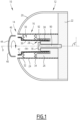
- the loudspeaker when finished, it is for example fixed on an outer casing. Then, the loudspeaker/outer casing assembly is fixed on the an internal structure 22 (see Figure 1 ) using a fixing screw (or other means of fixing).
- the diaphragm defines a central opening allowing access to the fixing screw using a screwdriver from outside the speaker and the acoustic enclosure. Once the speaker is fixed, a cover is added to the speaker to hide the opening defined by the diaphragm.
- the cover allows, during the manufacture of the loudspeaker, to center the moving part of the loudspeaker with its motor.
- the opening defined by the membrane to allow access to the fixing screw must ultimately be hidden by the cover, which detracts from the continuous and smooth appearance of the acoustic enclosure, and sometimes makes it unsightly in the eyes of users.
- the document FR 3 097 397 A1 describes an enclosure in which a loudspeaker is attached to a chassis using a screw passing through the loudspeaker's magnetic circuit.
- An aim of the invention is therefore to provide a loudspeaker whose structure is more continuous and smooth, so that it is perceived as more aesthetic by a user, while remaining easy to mount on the cabinet of an acoustic speaker.
- the invention relates to a loudspeaker according to claim 1.
- the loudspeaker comprises one or more of the features corresponding to claims 2 to 6, taken in isolation or in all the combinations claimed.
- the invention also relates to an acoustic enclosure according to claim 7.
- the invention also relates to a mounting method according to claim 8.
- the acoustic enclosure 10 comprises a box 12 defining an opening 14, a loudspeaker 16 extending across the opening 14 and defining an axis D, and a fixing system 18 adapted to fix the loudspeaker on the box.
- the acoustic enclosure 10 comprises one or more other loudspeakers, advantageously including a loudspeaker similar to the loudspeaker 16 and placed head to tail with the loudspeaker 16.
- the box 12 comprises an outer casing 20 which defines the opening 14, and an internal structure 22 attached to the casing 20, or, as a variant, made in one piece with the outer casing.
- the loudspeaker 16 is for example a bass loudspeaker, in the sense defined in the preamble above.
- the loudspeaker 16 is substantially of revolution around the axis D.
- the loudspeaker 16 comprises a chassis 24, a magnetic circuit 26 defining an air gap 28, and a moving element 30 adapted to vibrate relative to the magnetic circuit along the axis D.
- the loudspeaker 16 also advantageously comprises two suspensions 32, 34.
- the suspension 32 is a flexible joint connecting the moving assembly 30 to the chassis 24.
- the flexible seal 32 has, for example, a “U” shaped section along a radial half-plane P ( Figure 2 ).
- suspension 34 is a corrugated or pleated joint, known under the English name of “ spider ”, connecting for example the mobile assembly 30 to the chassis 24.
- the moving assembly 30 comprises a coil holder 36, and a coil 38 fixed on the coil holder and located in the air gap 28.
- the moving assembly comprises a membrane 40 adapted to emit sound waves, and a connecting system 42 rigidly connecting the membrane and the coil holder 36, the membrane defining a front side of the loudspeaker along the axis D.
- the spool holder 36 is for example cylindrical.
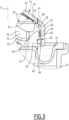
- the membrane 40 is reversibly movable between a mounted position (shown in the Figure 2 ), in which the membrane is integral with the connecting system 42, and a dismantled position (shown on the Figure 1 ), in which the membrane is away from the connecting system. In the mounted position, the membrane 40 forms a screen between the exterior of the loudspeaker and the magnetic circuit 26.
- forms a screen we mean that the membrane prevents access to the magnetic circuit from the front side of the speaker in the mounted position.
- the membrane 40 is advantageously made of plastic, for example ABS (acrylonitrile butadiene styrene).
- the membrane In the mounted position, the membrane is screwed onto the connecting system 42.
- the membrane and the connecting system are tightened with a tightening torque around the axis D greater than or equal to 0.05 N.m, preferably greater than or equal to 0.5 N.m, and even more preferably 4 N.m, or even 9 N.m.
- the membrane has an external thread and is screwed into the connection system.
- the membrane comprises a central portion 44, a threaded portion 46, and advantageously a plurality of ribs 50.
- the membrane has a diameter D1 perpendicular to the axis D. In the mounted position, the membrane and the connecting system 42 exert pressure forces on each other having an axial resultant R.
- the central part 44 forms, for example, a dome directed axially forward in the mounted position of the membrane.
- the central part 44 comprises a front face 52 which is advantageously smooth, and a rear face 54 carrying the ribs 50.
- the central part 44 forms, for example, a portion of a sphere.
- the central part 44 is devoid of any opening.
- the threaded part 46 extends for example axially towards the rear from an edge 56 of the central part 44.
- the threaded part 46 has for example a general cylindrical shape of axis D, forming a skirt at the periphery of the central part 44.
- the threaded part 46 has, for example, a thickness substantially equal to that of the central part 44, and advantageously between 0.2 and 8 mm.
- the threaded part 46 forms a thread 58 adapted to cooperate with the connecting system 42.
- the 58 thread forms a single-turn helix around the D axis.
- the thread 58 comprises several helices distinct from each other.
- the ribs 50 extend radially, advantageously from a crown 60 centered on the axis D.
- the ribs 50 have an axial extension E which is advantageously maximum at the level of the crown 60, and which reduces as one moves away from the axis D.
- the axial extension E becomes zero in a peripheral zone 60 of the rear face 54.
- the connecting system 42 comprises a radially inner end piece 62 fixed to the coil holder 36, and a radially outer end piece 64 defining an external thread 66 around the axis D configured to cooperate with the threaded part 46 of the membrane.
- the connecting system 42 comprises a first plurality of arms 68 extending radially between the end pieces 62 and 64, and advantageously a second plurality of arms 70 extending axially rearward from the end piece 64, or alternatively from the arms 68.
- the end piece 62 is for example of revolution around the axis D.
- the end piece 62 advantageously defines a slot 72 in which the reel holder 36 is received.
- the arms 70 are advantageously distributed discreetly around the axis D.
- the arms 70 respectively comprise ends 74 on which the suspension 34 is fixed.
- the arms 68 are advantageously distributed discreetly around the axis D.
- Each of the arms 68 comprises, for example, a base 76 connecting the end pieces 62 and 64, and a stiffening rib 78 extending radially.
- the end piece 64 has a lower face 80 on which the suspension 32 is fixed, the base of the “U” of the suspension being directed axially towards the rear.
- the end piece 64 defines an annular groove 82 receiving a seal 84 compressed radially between the end piece 64 and the threaded portion 46 of the membrane in the mounted position.
- the tip 64 forms, for example, a protuberance 86 abutting axially against a peripheral part 88 of the central part 44 of the membrane.
- the peripheral portion 88 is located radially between the portion 60, where the ribs 50 are interrupted, and the edge 56 of the membrane.
- the protuberance 86 exerts pressure forces on the membrane, the axial resultant R1 of which is shown in the Figure 3 .
- the thread 66 of the end piece 64 exerts pressure forces on the thread 58 of the membrane, the axial resultant R2 of which is shown in the Figure 3 .
- the fixing system 18 is for example a screw 90 received in an axial housing 92 passing through the magnetic motor 26.
- the screw head 92 is accessible from outside the loudspeaker 16 when the membrane 40 is in the disassembled and removed position, via a housing 94 defined by the coil holder 36 and the connecting system 42 and opening axially towards the front.
- the loudspeaker 16 is assembled without the membrane 40, that is to say the latter is in the disassembled position. During this entire phase, access to the housing 94 is possible from outside the loudspeaker, which facilitates the centering of the coil holder 36 and the connection system 42 relative to the magnetic circuit 26.
- the loudspeaker 16 still without the membrane 40, is placed across the opening 14 against the internal structure 22 of the box 12.
- the loudspeaker 16, without the membrane is then fixed to the box using the fixing system 18, that is to say by screwing the screw 90 into the box.
- This screwing operation is carried out by acting on the head 92 of the screw using a tool (not shown) introduced into the housing 94 from outside the acoustic enclosure.
- the membrane 40 is reversibly moved from the disassembled position to the assembled position.
- the membrane 40 is screwed onto the connecting system 42.
- the screwing is carried out until the desired tightening torque is obtained around the D axis.
- the membrane 40 and the connecting system 42 then exert on each other the pressure forces already mentioned.
- the protrusion 86 of the end piece 64 of the connecting system exerts on the membrane pressure forces with an axial resultant R1.
- the membrane exerts on the protrusion pressure forces whose axial resultant is opposite to R1.
- the thread 66 of the end piece 64 exerts on the thread 58 of the threaded part 46 of the membrane pressure forces having the axial resultant R2.
- the thread 58 in return exerts pressure forces on the thread 66 whose axial resultant is opposite to R2.
- the membrane 40 is assembled last and does not need to define an access opening to the fixing system 18. Consequently, in the mounted position, the membrane forms a screen between the exterior of the loudspeaker 16 and the magnetic circuit 26. Thus, a cover is not necessary, and the loudspeaker has a more continuous and smooth external appearance than in the prior art.
- the membrane 40 Since the membrane 40 is mounted reversibly, it can be easily removed without risk of damaging the loudspeaker 16. However, the value of the tightening torque advantageously prevents a user from easily removing the membrane 40.
- the assembly of the membrane 40 on the rest of the mobile assembly 30 advantageously does not require any glue, and makes it possible to achieve the desired stiffness.
Landscapes
- Engineering & Computer Science (AREA)
- Physics & Mathematics (AREA)
- Acoustics & Sound (AREA)
- Signal Processing (AREA)
- Multimedia (AREA)
- Manufacturing & Machinery (AREA)
- Audible-Bandwidth Dynamoelectric Transducers Other Than Pickups (AREA)
- Details Of Audible-Bandwidth Transducers (AREA)
Claims (8)
- Lautsprecher (16), umfassend:- einen Magnetkreis (26), der mindestens einen Luftspalt (28) definiert, und- ein bewegliches Organ (30), das angepasst ist, um in Bezug auf den Magnetkreis (26) entlang einer Achse (D) des Lautsprechers (16) zu schwingen, das bewegliche Organ (30) umfassend einen Spulenträger (36), eine Spule (38), die an dem Spulenträger (36) befestigt ist und sich in dem Luftspalt (28) befindet, eine Membran (40), die zum Emittieren von Schallwellen angepasst ist, und ein Verbindungssystem (42), das die Membran (40) und den Spulenträger (36) verbindet, wobei die Membran (40) eine Vorderseite des Lautsprechers (16) entlang der Achse (D) definiert,wobei:- die Membran (40) in Bezug auf das Verbindungssystem (42) zwischen einer montierten Position, in der die Membran (40) fest mit dem Verbindungssystem (42) verbunden ist, und einer demontierten Position, in der die Membran (40) von dem Verbindungssystem (42) entfernt ist, reversibel bewegbar ist, und- die Membran (40) in der montierten Position eine Abschirmung zwischen der Außenseite des Lautsprechers (16) und dem Magnetkreis (26) bildet, indem sie einem Zugang zu dem Magnetkreis (26) von der Vorderseite des Lautsprechers (16) aus in der montierten Position entgegenwirkt,dadurch gekennzeichnet, dass die Membran (40) einen Gewindeabschnitt (46) aufweist, der angepasst ist, um in der montierten Position entlang der Achse (D) in oder auf das Verbindungssystem (42) geschraubt zu werden.
- Lautsprecher (16) nach Anspruch 1, wobei die Membran (40) und das Verbindungssystem (42) in der montierten Position mit einem Drehmoment größer als oder gleich wie 0,05 Nm um die Achse (D) festgezogen sind.
- Lautsprecher (16) nach Anspruch 1 oder 2, wobei das Verbindungssystem (42) ein Endstück (64) umfasst, das ein Außengewinde (66) um die Achse (D) definiert, wobei das Außengewinde (66) konfiguriert ist, um mit dem Gewindeabschnitt (46) der Membran (40) zusammenzuwirken.
- Lautsprecher (16) nach Anspruch 3, wobei das Endstück (64) eine ringförmige Nut (82) definiert, der Lautsprecher (16) umfassend eine Dichtung (84), die in der Nut (82) aufgenommen und in der montierten Position radial zwischen dem Endstück (64) und dem Gewindeabschnitt (46) der Membran (40) zusammengedrückt ist.
- Lautsprecher (16) nach Anspruch 3 oder 4, wobei die Membran (40) einen mittleren Abschnitt (44) umfasst, der eine Kuppel bildet, die in der montierten Position axial zur Außenseite des Lautsprechers (16) gerichtet ist, wobei die Spitze (64) vorzugsweise einen Vorsprung (86) bildet, der in der montierten Position axial an einem Umfangsabschnitt (88) des mittleren Abschnitts (44) anliegt.
- Lautsprecher (16) nach einem der Ansprüche 1 bis 5, wobei die Membran (40) aus Kunststoff, z. B. Acrylnitril-Butadien-Styrol, ist und eine Innenseite (54) umfasst, die vorzugsweise radiale Rippen (50) definiert.
- Lautsprecherbox (10), umfassend:- ein Gehäuse (12),- mindestens einen Lautsprecher (16) nach einem der Ansprüche 1 bis 6, und- ein Befestigungssystem (18), das angepasst ist, um den Lautsprecher (16) selektiv an dem Gehäuse (12) zu befestigen, wobei das Befestigungssystem (18) den Magnetkreis (26) durchquert und von der Vorderseite des Lautsprechers (16) aus zugänglich ist, wenn die Membran (40) in der demontierten Position ist.
- Verfahren zur Montage einer Lautsprecherbox (10) nach Anspruch 7, umfassend die folgenden Schritte:- Befestigen des Lautsprechers (16) an dem Gehäuse (12) mittels des Befestigungssystems (18), das von der Vorderseite des Lautsprechers (16) aus zugänglich ist, wobei die Membran (40) in der demontierten Position ist, und- Bewegen der Membran (40) umkehrbar von der demontierten Position in die montierte Position.
Applications Claiming Priority (1)
| Application Number | Priority Date | Filing Date | Title |
|---|---|---|---|
| FR2108195A FR3125910B1 (fr) | 2021-07-28 | 2021-07-28 | Haut-parleur comprenant une membrane montée réversiblement, et enceinte acoustique intégrant un tel haut-parleur |
Publications (2)
| Publication Number | Publication Date |
|---|---|
| EP4125085A1 EP4125085A1 (de) | 2023-02-01 |
| EP4125085B1 true EP4125085B1 (de) | 2025-04-23 |
Family
ID=77711155
Family Applications (1)
| Application Number | Title | Priority Date | Filing Date |
|---|---|---|---|
| EP22187133.8A Active EP4125085B1 (de) | 2021-07-28 | 2022-07-27 | Lautsprecher mit einer reversibel montierten membran und akustisches gehäuse mit einem solchen lautsprecher |
Country Status (3)
| Country | Link |
|---|---|
| EP (1) | EP4125085B1 (de) |
| CN (1) | CN115696146A (de) |
| FR (1) | FR3125910B1 (de) |
Family Cites Families (2)
| Publication number | Priority date | Publication date | Assignee | Title |
|---|---|---|---|---|
| US4559584A (en) * | 1984-05-03 | 1985-12-17 | Victor Company Of Japan, Limited | Combination lighting device and loudspeaker |
| FR3097397B1 (fr) * | 2019-06-12 | 2022-07-22 | Devialet | Enceinte acoustique simplifiée |
-
2021
- 2021-07-28 FR FR2108195A patent/FR3125910B1/fr active Active
-
2022
- 2022-07-27 EP EP22187133.8A patent/EP4125085B1/de active Active
- 2022-07-27 CN CN202210894902.9A patent/CN115696146A/zh active Pending
Also Published As
| Publication number | Publication date |
|---|---|
| FR3125910A1 (fr) | 2023-02-03 |
| FR3125910B1 (fr) | 2024-03-29 |
| CN115696146A (zh) | 2023-02-03 |
| EP4125085A1 (de) | 2023-02-01 |
Similar Documents
| Publication | Publication Date | Title |
|---|---|---|
| EP3637790B1 (de) | Lautsprecherbox mit zwei entgegengesetzt fixierten lautsprechern auf einer innenverschalung | |
| FR2541194A1 (fr) | Dispositif pour la fixation des roues de vehicules | |
| EP1916182B1 (de) | Fahrrad-Steuerkopflager | |
| FR2520962A1 (fr) | Transducteur a membrane plate et procede de realisation de ce transducteur | |
| EP1306576A1 (de) | Hydraulisches, schwingungsdämpfendes Lager mit einem verrasteten Entkopplungsventil | |
| EP3371984B1 (de) | Mehrfachverglastes fenster mit einer geräuschreduzierungsvorrichtung | |
| EP3540523B1 (de) | Armbanduhr, die ein uhrengehäuse mit zwei zifferblättern umfasst | |
| FR3047125A1 (fr) | Ensemble de support d'un moteur electrique, notamment dans un dispositif de chauffage, ventilation et/ou climatisation pour vehicule automobile | |
| EP3078211B1 (de) | Elektrodynamischer kompakter lautsprecher mit einer konvexen membran | |
| EP4125085B1 (de) | Lautsprecher mit einer reversibel montierten membran und akustisches gehäuse mit einem solchen lautsprecher | |
| CH691335A5 (fr) | Appareil susceptible d'être immergé et comprenant un transducteur sonore. | |
| EP4113506B1 (de) | Akustische lautsprecherbox mit einem gehäuse und einem drehbar montierten lautsprecher | |
| FR3045264A1 (fr) | Membrane acoustique pour haut-parleur et haut-parleur correspondant | |
| EP3637787B1 (de) | Lautsprecherbox, die ein gehäuse aus monoblock-kunststoffmaterial umfasst | |
| EP1752290B1 (de) | Adapterhülse und entsprechende Zusammenbau und Montageverfahren | |
| EP1646797B1 (de) | Verfahren zum ausgleich eines kupplungsmechanismus und abdeckung dafür | |
| EP3632132A1 (de) | Akustische kammer mit reduziertem zischen | |
| FR3097397A1 (fr) | Enceinte acoustique simplifiée | |
| FR3058021B1 (fr) | Moteur de haut-parleur, haut-parleur et procede de centrage d'une membrane de haut-parleur | |
| EP3637788B1 (de) | Elektrodynamischer lautsprecher, der eine elastische halterung zum stützen eines flexiblen leiters umfasst | |
| FR3087068A1 (fr) | Haut-parleur electrodynamique comportant un treillis | |
| FR2977923A1 (fr) | Systeme d'amortissement des vibrations fixe sur deux cables paralleles | |
| FR3012716A1 (fr) | Enceinte acoustique a au moins un haut-parleur a membrane mobile convexe en continuite de forme avec un organe adjacent | |
| WO2023110940A1 (fr) | Groupe moto-ventilateur pour installation de chauffage, ventilation et/ou climatisation d'un véhicule automobile équipé d'un moyen de contact posé entre une coupelle et un moyeu | |
| FR3067202A1 (fr) | Haut-parleur electrodynamique avec joint de suspension centre |
Legal Events
| Date | Code | Title | Description |
|---|---|---|---|
| PUAI | Public reference made under article 153(3) epc to a published international application that has entered the european phase |
Free format text: ORIGINAL CODE: 0009012 |
|
| STAA | Information on the status of an ep patent application or granted ep patent |
Free format text: STATUS: THE APPLICATION HAS BEEN PUBLISHED |
|
| AK | Designated contracting states |
Kind code of ref document: A1 Designated state(s): AL AT BE BG CH CY CZ DE DK EE ES FI FR GB GR HR HU IE IS IT LI LT LU LV MC MK MT NL NO PL PT RO RS SE SI SK SM TR |
|
| P01 | Opt-out of the competence of the unified patent court (upc) registered |
Effective date: 20230425 |
|
| STAA | Information on the status of an ep patent application or granted ep patent |
Free format text: STATUS: REQUEST FOR EXAMINATION WAS MADE |
|
| 17P | Request for examination filed |
Effective date: 20230630 |
|
| RBV | Designated contracting states (corrected) |
Designated state(s): AL AT BE BG CH CY CZ DE DK EE ES FI FR GB GR HR HU IE IS IT LI LT LU LV MC MK MT NL NO PL PT RO RS SE SI SK SM TR |
|
| GRAP | Despatch of communication of intention to grant a patent |
Free format text: ORIGINAL CODE: EPIDOSNIGR1 |
|
| STAA | Information on the status of an ep patent application or granted ep patent |
Free format text: STATUS: GRANT OF PATENT IS INTENDED |
|
| RIC1 | Information provided on ipc code assigned before grant |
Ipc: H04R 7/14 20060101ALN20241116BHEP Ipc: H04R 31/00 20060101ALI20241116BHEP Ipc: H04R 9/06 20060101ALI20241116BHEP Ipc: H04R 9/04 20060101ALI20241116BHEP Ipc: H04R 7/22 20060101ALI20241116BHEP Ipc: H04R 7/16 20060101ALI20241116BHEP Ipc: H04R 7/12 20060101ALI20241116BHEP Ipc: H04R 1/02 20060101ALI20241116BHEP Ipc: G10K 9/22 20060101AFI20241116BHEP |
|
| INTG | Intention to grant announced |
Effective date: 20241127 |
|
| GRAS | Grant fee paid |
Free format text: ORIGINAL CODE: EPIDOSNIGR3 |
|
| GRAA | (expected) grant |
Free format text: ORIGINAL CODE: 0009210 |
|
| STAA | Information on the status of an ep patent application or granted ep patent |
Free format text: STATUS: THE PATENT HAS BEEN GRANTED |
|
| AK | Designated contracting states |
Kind code of ref document: B1 Designated state(s): AL AT BE BG CH CY CZ DE DK EE ES FI FR GB GR HR HU IE IS IT LI LT LU LV MC MK MT NL NO PL PT RO RS SE SI SK SM TR |
|
| REG | Reference to a national code |
Ref country code: GB Ref legal event code: FG4D Free format text: NOT ENGLISH |
|
| REG | Reference to a national code |
Ref country code: CH Ref legal event code: EP |
|
| REG | Reference to a national code |
Ref country code: DE Ref legal event code: R096 Ref document number: 602022013443 Country of ref document: DE |
|
| REG | Reference to a national code |
Ref country code: IE Ref legal event code: FG4D Free format text: LANGUAGE OF EP DOCUMENT: FRENCH |
|
| REG | Reference to a national code |
Ref country code: NL Ref legal event code: MP Effective date: 20250423 |
|
| PG25 | Lapsed in a contracting state [announced via postgrant information from national office to epo] |
Ref country code: NL Free format text: LAPSE BECAUSE OF FAILURE TO SUBMIT A TRANSLATION OF THE DESCRIPTION OR TO PAY THE FEE WITHIN THE PRESCRIBED TIME-LIMIT Effective date: 20250423 |
|
| REG | Reference to a national code |
Ref country code: AT Ref legal event code: MK05 Ref document number: 1788599 Country of ref document: AT Kind code of ref document: T Effective date: 20250423 |
|
| PG25 | Lapsed in a contracting state [announced via postgrant information from national office to epo] |
Ref country code: FI Free format text: LAPSE BECAUSE OF FAILURE TO SUBMIT A TRANSLATION OF THE DESCRIPTION OR TO PAY THE FEE WITHIN THE PRESCRIBED TIME-LIMIT Effective date: 20250423 Ref country code: PT Free format text: LAPSE BECAUSE OF FAILURE TO SUBMIT A TRANSLATION OF THE DESCRIPTION OR TO PAY THE FEE WITHIN THE PRESCRIBED TIME-LIMIT Effective date: 20250825 Ref country code: ES Free format text: LAPSE BECAUSE OF FAILURE TO SUBMIT A TRANSLATION OF THE DESCRIPTION OR TO PAY THE FEE WITHIN THE PRESCRIBED TIME-LIMIT Effective date: 20250423 |
|
| REG | Reference to a national code |
Ref country code: LT Ref legal event code: MG9D |
|
| PG25 | Lapsed in a contracting state [announced via postgrant information from national office to epo] |
Ref country code: GR Free format text: LAPSE BECAUSE OF FAILURE TO SUBMIT A TRANSLATION OF THE DESCRIPTION OR TO PAY THE FEE WITHIN THE PRESCRIBED TIME-LIMIT Effective date: 20250724 Ref country code: NO Free format text: LAPSE BECAUSE OF FAILURE TO SUBMIT A TRANSLATION OF THE DESCRIPTION OR TO PAY THE FEE WITHIN THE PRESCRIBED TIME-LIMIT Effective date: 20250723 |
|
| PG25 | Lapsed in a contracting state [announced via postgrant information from national office to epo] |
Ref country code: PL Free format text: LAPSE BECAUSE OF FAILURE TO SUBMIT A TRANSLATION OF THE DESCRIPTION OR TO PAY THE FEE WITHIN THE PRESCRIBED TIME-LIMIT Effective date: 20250423 |
|
| PG25 | Lapsed in a contracting state [announced via postgrant information from national office to epo] |
Ref country code: BG Free format text: LAPSE BECAUSE OF FAILURE TO SUBMIT A TRANSLATION OF THE DESCRIPTION OR TO PAY THE FEE WITHIN THE PRESCRIBED TIME-LIMIT Effective date: 20250423 |
|
| PG25 | Lapsed in a contracting state [announced via postgrant information from national office to epo] |
Ref country code: HR Free format text: LAPSE BECAUSE OF FAILURE TO SUBMIT A TRANSLATION OF THE DESCRIPTION OR TO PAY THE FEE WITHIN THE PRESCRIBED TIME-LIMIT Effective date: 20250423 |
|
| PG25 | Lapsed in a contracting state [announced via postgrant information from national office to epo] |
Ref country code: AT Free format text: LAPSE BECAUSE OF FAILURE TO SUBMIT A TRANSLATION OF THE DESCRIPTION OR TO PAY THE FEE WITHIN THE PRESCRIBED TIME-LIMIT Effective date: 20250423 |
|
| PG25 | Lapsed in a contracting state [announced via postgrant information from national office to epo] |
Ref country code: RS Free format text: LAPSE BECAUSE OF FAILURE TO SUBMIT A TRANSLATION OF THE DESCRIPTION OR TO PAY THE FEE WITHIN THE PRESCRIBED TIME-LIMIT Effective date: 20250723 |
|
| PG25 | Lapsed in a contracting state [announced via postgrant information from national office to epo] |
Ref country code: IS Free format text: LAPSE BECAUSE OF FAILURE TO SUBMIT A TRANSLATION OF THE DESCRIPTION OR TO PAY THE FEE WITHIN THE PRESCRIBED TIME-LIMIT Effective date: 20250823 |
|
| PG25 | Lapsed in a contracting state [announced via postgrant information from national office to epo] |
Ref country code: LV Free format text: LAPSE BECAUSE OF FAILURE TO SUBMIT A TRANSLATION OF THE DESCRIPTION OR TO PAY THE FEE WITHIN THE PRESCRIBED TIME-LIMIT Effective date: 20250423 |
|
| PG25 | Lapsed in a contracting state [announced via postgrant information from national office to epo] |
Ref country code: SM Free format text: LAPSE BECAUSE OF FAILURE TO SUBMIT A TRANSLATION OF THE DESCRIPTION OR TO PAY THE FEE WITHIN THE PRESCRIBED TIME-LIMIT Effective date: 20250423 Ref country code: DK Free format text: LAPSE BECAUSE OF FAILURE TO SUBMIT A TRANSLATION OF THE DESCRIPTION OR TO PAY THE FEE WITHIN THE PRESCRIBED TIME-LIMIT Effective date: 20250423 |
|
| PG25 | Lapsed in a contracting state [announced via postgrant information from national office to epo] |
Ref country code: CZ Free format text: LAPSE BECAUSE OF FAILURE TO SUBMIT A TRANSLATION OF THE DESCRIPTION OR TO PAY THE FEE WITHIN THE PRESCRIBED TIME-LIMIT Effective date: 20250423 |
|
| PG25 | Lapsed in a contracting state [announced via postgrant information from national office to epo] |
Ref country code: EE Free format text: LAPSE BECAUSE OF FAILURE TO SUBMIT A TRANSLATION OF THE DESCRIPTION OR TO PAY THE FEE WITHIN THE PRESCRIBED TIME-LIMIT Effective date: 20250423 |
|
| REG | Reference to a national code |
Ref country code: DE Ref legal event code: R097 Ref document number: 602022013443 Country of ref document: DE |
|
| PG25 | Lapsed in a contracting state [announced via postgrant information from national office to epo] |
Ref country code: SK Free format text: LAPSE BECAUSE OF FAILURE TO SUBMIT A TRANSLATION OF THE DESCRIPTION OR TO PAY THE FEE WITHIN THE PRESCRIBED TIME-LIMIT Effective date: 20250423 |
|
| PG25 | Lapsed in a contracting state [announced via postgrant information from national office to epo] |
Ref country code: IT Free format text: LAPSE BECAUSE OF FAILURE TO SUBMIT A TRANSLATION OF THE DESCRIPTION OR TO PAY THE FEE WITHIN THE PRESCRIBED TIME-LIMIT Effective date: 20250423 |
|
| REG | Reference to a national code |
Ref country code: DE Ref legal event code: R119 Ref document number: 602022013443 Country of ref document: DE |
|
| PG25 | Lapsed in a contracting state [announced via postgrant information from national office to epo] |
Ref country code: RO Free format text: LAPSE BECAUSE OF FAILURE TO SUBMIT A TRANSLATION OF THE DESCRIPTION OR TO PAY THE FEE WITHIN THE PRESCRIBED TIME-LIMIT Effective date: 20250423 |
|
| REG | Reference to a national code |
Ref country code: CH Ref legal event code: H13 Free format text: ST27 STATUS EVENT CODE: U-0-0-H10-H13 (AS PROVIDED BY THE NATIONAL OFFICE) Effective date: 20260224 |
|
| PLBE | No opposition filed within time limit |
Free format text: ORIGINAL CODE: 0009261 |
|
| STAA | Information on the status of an ep patent application or granted ep patent |
Free format text: STATUS: NO OPPOSITION FILED WITHIN TIME LIMIT |
|
| REG | Reference to a national code |
Ref country code: CH Ref legal event code: L10 Free format text: ST27 STATUS EVENT CODE: U-0-0-L10-L00 (AS PROVIDED BY THE NATIONAL OFFICE) Effective date: 20260304 |
|
| PG25 | Lapsed in a contracting state [announced via postgrant information from national office to epo] |
Ref country code: LU Free format text: LAPSE BECAUSE OF NON-PAYMENT OF DUE FEES Effective date: 20250727 |