EP4124866B1 - System and method for cleaning an analyzer probe - Google Patents
System and method for cleaning an analyzer probe Download PDFInfo
- Publication number
- EP4124866B1 EP4124866B1 EP22186417.6A EP22186417A EP4124866B1 EP 4124866 B1 EP4124866 B1 EP 4124866B1 EP 22186417 A EP22186417 A EP 22186417A EP 4124866 B1 EP4124866 B1 EP 4124866B1
- Authority
- EP
- European Patent Office
- Prior art keywords
- air
- probe
- liquid
- cleaning device
- inner chamber
- Prior art date
- Legal status (The legal status is an assumption and is not a legal conclusion. Google has not performed a legal analysis and makes no representation as to the accuracy of the status listed.)
- Active
Links
Images




Classifications
-
- B—PERFORMING OPERATIONS; TRANSPORTING
- B08—CLEANING
- B08B—CLEANING IN GENERAL; PREVENTION OF FOULING IN GENERAL
- B08B3/00—Cleaning by methods involving the use or presence of liquid or steam
- B08B3/02—Cleaning by the force of jets or sprays
-
- B—PERFORMING OPERATIONS; TRANSPORTING
- B08—CLEANING
- B08B—CLEANING IN GENERAL; PREVENTION OF FOULING IN GENERAL
- B08B5/00—Cleaning by methods involving the use of air flow or gas flow
- B08B5/02—Cleaning by the force of jets, e.g. blowing-out cavities
-
- G—PHYSICS
- G01—MEASURING; TESTING
- G01N—INVESTIGATING OR ANALYSING MATERIALS BY DETERMINING THEIR CHEMICAL OR PHYSICAL PROPERTIES
- G01N35/00—Automatic analysis not limited to methods or materials provided for in any single one of groups G01N1/00 - G01N33/00; Handling materials therefor
- G01N35/10—Devices for transferring samples or any liquids to, in, or from, the analysis apparatus, e.g. suction devices, injection devices
- G01N35/1004—Cleaning sample transfer devices
Definitions
- This disclosure relates to cleaning systems and methods, and more particularly to systems and methods for cleaning analyzer probes.
- a probe may be used to extract a sample from a container for testing.
- Fluid probes are commonly used for accessing and transferring materials. The probe may be cleaned regularly to avoid material contamination and carryover.
- JP S 62 242858 A describes a cleaning device to quickly clean a probe in such a manner that the probe can be freely inserted into and pulled upward from a cleaning chamber.
- the probe is so constituted that the probe can be freely inserted into and pulled upward form the cleaning chamber.
- Pure water is injected from plural pieces of a water injection nozzles diagonally provided to point to the central axis of the cleaning chamber when the probe is inserted in the central axis direction of the cleaning chamber. Cleaning is executed as the probe moves.
- An immersion cleaning tank is provided below the water injection nozzles and the probe is cleaned in the fluidized pure water supplied from a water feed pipe. Compressed air is blown to the probe from plural pieces of air injection nozzles provided above the water injection nozzles at the time when the probe is pulled upward after cleaning thereof, by which the probe is dried.
- US 4 495 149 A describes an analyzing apparatus for applying samples and reagents to the surface of a reaction carrier and for optically analyzing each component contained in the various samples.
- the dispensing of the samples and reagents and the optical detection operation are performed by an optics/dispensing mechanism moved relative to the reaction carrier in two dimensions.
- the optics/dispensing mechanism is combined with a cleaning apparatus for cleansing reagents and samples from a dispensing needle by means of a rinsing agent and air ejected toward the needle.
- the apparatus further includes an automatic lifting mechanism for lifting and replacing a cover disposed on the reaction carrier, and is adapted to move the dispensing needle to a position over a nearby reagent/sample holder so that the needle may take up a desired reagent or sample from the holder and transfer it to the surface of the reaction carrier.
- US 10 670 619 B2 describes a device that can clean at least one pipetting needle with a washing station.
- the inside and an outside of the pipetting needle are brought into contact at least for a portion with a washing liquid, at least temporarily during a cleaning process, and with at least one movement apparatus by which a relative movement is brought about between the pipetting needle and the washing station at least temporarily before, after, or during the cleaning process.
- the device has a drying device, which subjects at least one region of the pipetting needle brought into contact with washing liquid during the cleaning process to at least one flow of a drying agent.
- JP 2013 134142 A describes an automatic analyzer which includes a sample dispensing unit that dispenses a sample into a reaction vessel, a reagent dispensing unit that dispenses a reagent, a sample nozzle cleaning tank that cleans a nozzle of the sample dispensing unit, a reagent nozzle cleaning tank that cleans a nozzle of the reagent dispensing unit, a compressor that supplies compressed air, and cleaning water supply means that supplies cleaning water.
- the tanks each have an upper vent that allows a nozzle to have access for cleaning, a lower vent that drains the cleaning water, a cleaning water jet port that sprays the cleaning water to the nozzle, and a compressed air jet port that removes residual cleaning water left on the nozzle.
- the lower vent has an opening area wider than that of the upper vent.
- JP 2011 078881 A describes a nozzle cleaning unit capable of cleaning a nozzle with higher efficiency.
- the nozzle cleaning unit mounted on a dispensing apparatus includes a cleaning vessel, a cleaning solution sprayer spraying a cleaning solution in the cleaning vessel, a drying sprayer spraying air to blow away the cleaning solution adhered to the nozzle into the cleaning vessel, a moving mechanism causing the nozzle to ascend and descend and a controller controlling those units.
- the controller repeats, at least twice, a set operation consisting of a cleaning process of spraying the cleaning solution while causing the nozzle to descend and a drying process of spraying air while causing the nozzle to ascend, after the cleaning process.
- US 2016/313361 A1 describes a piercer washing port which is provided at a position on the trajectory of a piercer differing from the sampling position.
- the piercer washing port is cylindrically shaped and has an opening for inserting the piercer in the upper surface and a washing space for housing the piercer inserted from the opening.
- Air injection ports for injecting air and washing liquid expelling ports for expelling water serving as a washing liquid are provided on the inside wall surface of the piercer washing port.
- the air injection ports are provided at four locations equally spaced on the periphery along the inside wall surface of the washing space.
- the washing liquid expelling ports are provided at four locations equally spaced on the periphery along the inside wall surface of the washing space at different positions than those of the air injection ports.
- WO2011/062982A1 also discloses a prior art cleaning device.
- the claimed invention includes a cleaning device for cleaning a probe as defined in claim 1 and a method of cleaning a probe using a cleaning device according to claim 9.
- An example cleaning device is for cleaning a probe.
- the cleaning device includes a body defining an inner chamber, the body comprising an opening proximate an upper end of the cleaning device, the opening allowing the probe to enter the inner chamber.
- the cleaning device includes an air intake connected to at least one air channel formed within the body, the at least one air channel being configured to allow air from the air intake to flow into the inner chamber.
- the cleaning device includes a liquid intake connected to at least one liquid channel formed within the body, the at least one liquid channel being configured to allow liquid from the liquid intake to flow into the inner chamber.
- the cleaning device may have a waste outlet proximate a lower end of the cleaning device.
- the at least one air channel of the cleaning device may be configured such that air flows towards a probe placed in the device at a vertically downward angle towards a tip of the probe.
- the at least one air channel of the cleaning device may be positioned vertically above the at least one liquid channel.
- the at least one air channel of the cleaning device may be a single air channel extending around a circumference of the inner chamber.
- the at least one air channel may be a single air channel and formed by a distance between opposing sidewalls, the distance including a first distance between the opposing sidewalls at a first end of the air channel at the inner chamber.
- the distance further includes a second distance being at a second end of the air channel at the air intake, the first distance being less than the second distance.
- the opposing sidewalls of the cleaning device may extend into the inner chamber.
- the at least one air channel of the cleaning device may comprise a plurality of separate air channels, each air channel forming a cylindrical tunnel through the body and into the inner chamber.
- the at least one liquid channel may further comprise a plurality of separate liquid channels, each liquid channel forming a cylindrical tunnel through the body and into the inner chamber.
- the separate air channels of the cleaning device may be spaced around a circumference of the inner chamber.
- the separate liquid channels of the cleaning device may be spaced around the circumference of the inner chamber.
- the example cleaning device comprises a lower body positioned between the body and the waste outlet, the lower body defining a lower chamber around the axis and a path is formed between the body and the lower body for air to exit the cleaning device.
- An example method is for cleaning a probe using a cleaning device.
- the method includes placing at least a part of the probe into a chamber of the cleaning device.
- Air is directed from an air intake and through an air channel of the cleaning device and towards the probe.
- Liquid is directed from a liquid intake through a plurality of liquid channels of the cleaning device and towards the probe at a position vertically below the air channel.
- the probe may be within a piercer and the method may include inserting the probe and piercer through the opening and into the chamber. The method may then include extending the probe from the piercer. The method may then include delivering a first liquid into the probe such that the first liquid passes through the probe and into a waste outlet proximate a lower end of the cleaning device. The method may then include turning on an air system of the cleaning device to pass air through the air intake and the at least one air channel into the inner chamber. The method may then include delivering a second liquid through the liquid intake and the at least one liquid channel into the inner chamber. The method may then include retracting the probe into the piercer. The method may then include lifting the probe to a position just above the air channel and stopping delivery of the first liquid into the probe. The method may then include lifting the probe and piercer out of the cleaning device. Finally, the method may include, after lifting the probe and piercer, turning off the air system and stopping the delivery of the second liquid into the inner chamber.
- the example method may include delivering a first liquid into the probe such that the first liquid passes through the probe and into a waste outlet proximate a lower end of the cleaning device.
- the method may then include turning on an air system of the cleaning device to pass air through the air intake and the at least one air channel into the inner chamber.
- the method may then include delivering a second liquid through the liquid intake and the at least one liquid channel into the inner chamber.
- the method may then include stopping delivery of the first liquid into the probe and lifting the probe out of the cleaning device. After lifting the probe, the method may then include turning off the air system and stopping the delivery of the second liquid into the inner chamber.
- the example method may include, during the step of passing air through the air intake and the at least one air channel into the inner chamber, passing the air into the inner chamber at a vertically downward angle.
- the air may be passed through the at least one air channel in an air stream such that the air stream narrows as it approaches the inner chamber.
- the method may include, after placing at least a part of the probe into a chamber of the cleaning device, delivering a first liquid into the probe such that the first liquid passes through the probe and into a waste outlet proximate a lower end of the cleaning device.
- the method may then include turning on an air system of the cleaning device to pass air through the air intake and the at least one air channel into the inner chamber.
- the method may then include delivering a second liquid through the liquid intake and the at least one liquid channel into the inner chamber.
- the method may then include stopping delivery of the first liquid into the probe and turning off the air system.
- the method may include stopping the delivery of the second liquid into the inner chamber and lifting the probe out of the cleaning device.
- FIGs. 1-6C show an example implementation of a cleaning device 100 for an analyzer probe 102 ( FIG. 2 ).
- the probe 102 is omitted to more clearly illustrate other features.
- the cleaning device 100 is configured to clean the analyzer probe 102 after the probe 102 has been used for sampling within an analyzer system. While the probe 102 is described as an analyzer probe 102 by way of example, it should be understood that the probe 102 may be any contact style probe for a fluid or sample handling system. In general, the probe 102 is effective when used within systems which work with any type of sample, including plasma, whole blood, urine, other bodily fluids, a non-biological sample, or others.
- the probe 102 can be cleaned either by a rinse (e.g. a water rinse) and dry process, or by chemical cleaning using chemically active cleaning materials.
- the probe 102 can be dipped or sprayed with the cleaning material. If chemicals are used, a second water rinsing step may be incorporated in the cleaning process to remove the chemical. The rinsing or washing step when not using chemicals will wet the probe and then dry. This can be a passive dip or active spray and is often accompanied by washing of the internal surface of the probe 102.
- the example probe 102 shown here is seated within a piercer 104, which can be used to puncture a sample container, although a probe 102 with no piercer 104 may also be used within the cleaning device 100.
- analyzer systems include robotic systems which can mechanically control the probe 102 to move the probe 102 within the system generally and guide the probe 102 to a location for cleaning.
- the cleaning device 100 includes an upper body 106, which defines a cylindrical inner chamber 108 within which the probe 102 and piercer 104 can be cleaned.
- An opening 110 is formed within the upper end of the body 106.
- the probe 102 is lowered, by a control system of the cleaning device 100, through the opening 110, into the inner chamber 108 along a central axis "y".
- a foot 112 of the probe 102 acts as a guide, situating the probe 102 within a seat 114 defined by the top of the body 106 of the cleaning device 100.
- the seat 114 engages the foot 112 of the probe 102 to assist in holding the probe 102 in place during cleaning.
- the probe 102 need not include a foot 112 in all cases.
- the device 100 includes an air intake 116 ( FIGs. 2 , 3 , and 5 ), defined by a solid outer wall around an open interior, which can be in fluid communication with an air system (not shown), such as an air pump or pressurized air canister, to receive air through the interior.
- an air system such as an air pump or pressurized air canister
- the outer wall of the air intake 116 is threaded to couple with a threaded nozzle 120 ( FIG. 3 ), by coupling the threads of the air intake 116 and threaded nozzle 120, the threaded nozzle 120 in turn connecting to the air system.
- the cleaning device 100 also includes a liquid intake 118, defined by a solid outer wall around an open interior, which can be in fluid communication with a liquid source (not shown).
- the liquid source can include deionized water, or another rinsing and/or cleaning agent.
- the liquid intake 118 is threaded to allow for coupling to a threaded nozzle 122, although other couplings, e.g., such as rivets, clips, screws, bolts, etc., can be used, or alternatively, no nozzle 122 can be used and the intake 118 can be connected directly to a liquid source.
- the threaded nozzle 122 enables connection of a water line leading to the liquid source.
- the cleaning liquid and the air can be sent to the intakes 116, 118 using one or more pumps.
- the cleaning liquid can be sent to the intake 118 via the force of gravity alone.
- An air channel 124 provides an opening through the body 106 and into the inner chamber 108 ( FIG. 3 ). As will be discussed in more detail below, the air channel 124 extends around the entire circumference of the probe 102, allowing air from the air intake 116 to flow into the inner chamber 108 and towards the probe 102 such that the air contacts the probe 102 around the entire circumference of the probe 102.
- One or more liquid channels 126 FIG. 3 ) provide an opening (e.g. a tube shaped tunnel) through the body 106 to direct rinse liquid from the liquid intake 118 into the inner chamber 108 and towards the probe 102.
- the channels 124, 126 can be angled at a vertically downward angle, to direct liquid or air into the inner chamber 108 and towards the probe 102 at a vertically downward angle in accordance with gravity. This allows waste on the probe 102 to be rinsed downward, consistent with the angle of the channels 124, 126, such that the waste passes through a lower chamber 128 of a lower body 130 and into a waste outlet 132.
- the waste outlet 132 ( FIG. 2 ) is defined by a solid wall forming an opening through which waste can pass.
- the waste outlet 132 is connected to a waste nozzle 133, e.g., through threads or other mechanisms such as rivets, clips, screws, bolts, etc., for directing waste, e.g., through a waste line, out of the device 100 for capture and disposal.
- the lower chamber 128 extends the overall length of the inner chamber 108 such that the probe 102 fits within the device 100.
- an air channel 124 extends within the body 106 for directing air.
- the air channel 124 is formed between sidewalls 134, 136 formed by two separate surfaces of the body 106 separated by a distance 138a, 138b.
- the height of the air channel 124 i.e. the distance 138a, 138b between the sidewalls 134, 136) decreases as the air channel 124 approaches the inner chamber 108, forming a narrowing slot. More particularly, the distance 138a is greater at an end of the air channel 124 at the air intake 116, and the distance 138b is less at an end of the air channel near the inner chamber 108.
- a thin curtain of air may be particularly helpful in drying the probe 102 and directing the rinse liquid and waste downward toward the waste outlet 132, since the narrow curtain results in a greater downward pressure on the waste, as compared to the pressure that would be applied were the air stream not narrowed.
- the air channel 124 extends around the entire diameter of the inner chamber 108, providing air from multiple directions, e.g., all around and 360 degrees, around the probe 102.
- the sidewalls 134, 136 of the air channel 124 extend into (see extended walls 134a, 136a of FIG. 4 ) the inner chamber 108 and terminate in a narrow circumference 135 around the probe 102 (see e.g. FIG. 5 ). This can reduce the distance the air is required to travel to reach the probe 102 after leaving the air channel 124. Further, the extended sidewalls 134a, 136a can act a splatter shield, blocking cleaning liquid that splatters off the probe 102 during rinsing from exiting through the opening 110 of the body 106. In other implementations, differently shaped channels and/or additional channels may also be used as an alternative to the channels 124, 126 shown in the cleaning device 100.
- Flow arrows 140 in FIG. 3 depict an example path of air through the device 100.
- air reaches the intake 116, travels downward through the air channel 124, and contacts the probe 102.
- the air then passes downwards through the inner chamber 108, towards the lower chamber 128 of the lower body 130.
- the lower body 130 is connected to the upper body 106 by any mechanical means (e.g. screws) such that a separation distance 142 between the lower and upper bodies 130, 106 is maintained.
- the separation distance 142 provides a path 144 for the air out of the cleaning device cleaning 100, and prevents pressure from building up within the cleaning device 100 (e.g. from excessive air buildup in the lower chamber 128), which could result in misting and splatter during the cleaning process.
- the lower body 130 includes interior sidewalls 146 above the lower chamber 128 and the body 106 includes exterior sidewalls 148, which define the path 144, causing the path 144 to initially slope upwards and away from the central axis y before extending directly upwards and parallel to a central vertical axis "y" of the device 100. After extending straight upwards, the path 144 slopes horizontally away from the central axis y of the probe 102. Further, since the path 144 is defined by upwardly sloped walls 146, the path 144 can prevent rinse liquid or waste from exiting the through the path 114.
- Flows arrows 150 in FIG. 5 depict an example path of the rinse liquid through the device 100.
- a pump and liquid reservoir (not shown herein) provide liquid to the liquid intake 118. From the liquid intake 118, the liquid flows through a number of separate liquid channels 126, which can be cylindrically shaped holes through the body 106, and towards the probe 102. The liquid approaches the probe 102 at a vertically downwards angle ( FIG. 6A ). The rinse liquid strikes the probe 102 cleaning sample residue off the outer surface of the probe 102. The liquid then passes into the lower chamber 128 and exits the device 100 through the waste outlet 132 (and the nozzle 133, if included). Notably, in FIGs. 3 and 5 , the probe 102 is omitted for ease of illustration of the air and water flow 140, 150.
- the device 100 may include a plurality (e.g. three, four, five, or another number) of separate liquid channels 126, all individually connected to the liquid intake 118 for delivering liquid from the liquid intake 118 into the inner chamber 108.
- the example path of cleaning liquid after exiting the channels 126 is shown via liquid 152.
- the separate liquid channels 126 can be spaced equidistant from one another around the inner circumference 109 ( FIG. 6A ) of the inner chamber 108 to cause the rinse liquid 152 to strike the probe 102 (omitted for ease of illustration of the rinse liquid 152) at different sides of the probe, helping cleaning of the entire probe 102. While the probe 102 is omitted in FIG.
- the liquid 152 is shown as forming a ring 153 at the center where the liquid 152 would normally strike the probe 152 from multiple angles.
- the channels 126 can be cylindrically shaped, forming separate tunnels to direct jets of liquid 152 at the probe 102. This example arrangement may be effective for cleaning a probe 102 within the cleaning device 100. However, other shapes and orientations of liquid channels 126 may be used, such as cuboidal shaped or triangular shaped channels 126.
- the air channel 124 is positioned above the liquid channels 126 with along the direction of the central axis y.
- This arrangement can allow the air to contact the probe 102 location(s) above the location(s) where the rinse liquid 152 contacts the probe, moving the liquid 152 downward inside the device 100 and drying the probe 102 as the probe is lifted upwards and out of the inner chamber 108.
- the tip 158 of the probe 102 can initially be lowered into the inner chamber 108, with the lower portion 154 of the probe 102 eventually being positioned below the channels 126.
- the lower portion 154 of the probe 102, below the liquid channels 126 will be rinsed by the liquid 152 during cleaning.
- air and rinse liquid 152 can be provided through the channels 124, 126 and the probe 102 can be lifted to rinse and dry the lower area 154 of the probe 102 (and piercer 104 if included).
- an additional rinse line can be connected through the top end 156 ( FIG. 2 ) of the probe 102 (the probe 102 having a tubular structure) to provide rinse liquid to the interior of the probe 102.
- the liquid within the interior of the probe 102 can pass through the probe 102, exiting from the tip 158 of the probe 102 and passing to the waste outlet 132.
- the rinse liquid 152 from the liquid channels 126 comes into direct contact with the entire lower area 154 of the probe 102 to clean the lower area.
- air from the air channel 124 directly contacts the probe 102 as it is lifted, drying the entire lower area 154 of the probe 102 just after it is cleaned with the rinse liquid 152. Therefore, after the probe 102 is seated within the cleaning device 100, the probe 102 can be cleaned with a simple upward movement of the probe 102. This avoids the need for any further manipulation of the probe 102, resulting in a simple cleaning and drying sequence which can be carried out quickly to increase or to maximize throughput of the corresponding analyzer system.
- the upper body 106 of the cleaning device may be include members 160a, 160b, 160c, and 160d.
- the members 160a-160d can be formed separately and connected after formation, or one or more or the entire members can be formed as an integral part.
- a top member 160a is in the shape of a plate which forms the opening 110 and seat 114 for the probe 102.
- the air channel 124 is formed between the top member 160a and a central exterior member 160c.
- the bottom surface of the top member 160a forms one sidewall 136 of the air channel 124 ( FIG. 4 ).
- the opposing sidewall 134 of the air channel 124 is part of a surface of a central exterior member 160c ( FIG. 4 ).
- the air intake 116, the liquid intake 118, and a beginning 127 of the liquid channels 126 ( FIG. 5 ) proximate the intake 118 can be formed in the central exterior member 160c.
- the remainder of each liquid channel 126 is formed in a central interior member 160b that is located between the central exterior member 160c and the inner chamber 108.
- the central interior member 160b has an open center, defining the top portion of the inner chamber 108.
- a lower member 160d located adjacent to the members 160b, 160c forms the bottom of the upper body 106.
- An inner opening within the lower member 160d defines the bottom of the inner chamber 108 leading into the lower body 130.
- the lower member 160d includes a lower protruding end 162 having an outer diameter 163 smaller than an upper inner diameter 165 of the body 130 ( FIG. 3 ). This allows the lower end 162 to be contained within the lower body 130.
- the exterior sidewalls 148 of the lower end 162 define one side of the air path 144, and interior sidewalls 146 of the lower body 130 form the opposing side of the air path 144.
- the central exterior member 160c and central interior member 160b each include a flange 164, 166, which couple to secure the central interior member 160b between the central exterior member 160c and the lower member 160d.
- O-rings 168 are provided between adjacent members 160a, 160b, 160c to create seals therebetween ( FIGs. 2-5 ).
- FIGs. 7-8 show another example implementation of a probe cleaning device 700.
- the device 700 is configured similarly to the device 100 shown in FIGs. 1-6C , except as otherwise shown and described herein.
- the device 700 includes air channels 702 for directing air which are constructed or formed similar to the liquid channels 126 described above.
- the air channels 702 can include a plurality (e.g. three, four, five, or another number) of separate tunnels, e.g., tube shaped tunnels, which direct air from an air intake 716 into the inner chamber 706 of the device 700, as indicated by air flow arrows 704.
- the air channels 702 can be spaced, e.g., in equal distance, around the circumference of the inner chamber 706 to dry the probe 708 from different directions.
- the liquid channels 720 can include a plurality (e.g. three, four, five, or another number) of tunnels which are similarly formed and located, below the air channels 702, to provide liquid (e.g. arrows 736) to the probe 708 for cleaning, as liquid channels 126.
- Waste liquid exits through the waste nozzle 740, which includes an outer wall defining an opening, similar to waste nozzle 133, while excess air can exit through air path 726 similar to air path 144.
- the upper body 710 of the cleaning device 700 includes two members 712a, 712b, separately formed and connected or integrally formed.
- Exterior member 712a defines the opening 714 for receiving the probe 708, the intakes 716, 718, and parts of the upper and liquid channels 702, 720.
- Nozzles 730, 732 connect to the intakes 702, 720 to provide air and liquid, respectively.
- the interior member 712b disperses air 704 and liquid 736 from the channels 702, 720 into the inner chamber 706 to contact the probe 708.
- a cylindrical opening in the center of the inner member 712b forms the top of the inner chamber 706.
- the lower portion of the inner chamber 706 is formed by a cylindrical opening in the bottom portion of the exterior member 712a.
- the top and bottom of the chamber 706 can have the same shape and size, e.g., the same diameter.
- the bottom portion of the exterior member 712a also forms a protruding lower end 722, which defines sidewalls of the air path 726.
- the exterior and interior members 712a, 712b can be sealed together with O-rings 738 on either side of both the upper and liquid channels 702, 720.
- the exterior member 712a can be rigidly connected to the lower body 724 by rods 742 in the air path 726 while keeping the air path open.
- FIG. 9 shows an example probe cleaning system 900 for use with the example probe cleaning devices described herein.
- the system 900 includes a cleaning device 902, which can include one of the cleaning devices 100, 700 shown and described herein.
- the cleaning device 902 has an air nozzle 904 and liquid nozzle 906 which connect the cleaning device 902 to air and liquid lines, respectively.
- the air nozzle 904 is fed air by an air system 908, which can include a pump, pressurized air canister, or other device for delivering air via a connected air line.
- the air system 908 When the air system 908 is turned on, air from the air system 908 passes to the air nozzle 904 and into an air intake of the cleaning device 902 to dry the probe 910 after the probe 910 is lowered into the cleaning device 902.
- a degassing module 912 can prepare liquid as cleaning liquid for use within the system 900. Degassing can be used for precision fluids, but it should be understood that degassing, and therefore the degassing module 912, are not required in all circumstances. For example, the degassing module 912 is not needed when the probe 902 is cleaned by rinsing with water.
- a rinse bottle 914 within the degassing module 912 includes a liquid, such as deionized water.
- a pump 916 transfers liquid from the rinse bottle 914, through a check valve 915 and to a degasser 918 (if included), which allows excess gas to bleed off as the liquid passes through.
- Some liquid can be circulated back to the rinse bottle 914 to create a holding loop for precision fluidics, if necessary. However, for cleaning with a water rinse, no recirculation back to the rinse bottle 914 is necessary. The liquid is then sufficient for use as a cleaning liquid.
- the degasser 918 When the degasser 918 is used, some additional water evaporates and transfers thought the degassing membrane, being pulled in by the vacuum pump 941 to then be ejected to a waste container 940.
- a pump 924 on the first line 920 is operable to direct the cleaning liquid through a check valve 926 and to the liquid nozzle 906 of the cleaning device 902.
- a pump 928 on the second line 922 is operable to direct cleaning liquid to a syringe pump 932 connected to the probe 910.
- the syringe pump 932 is operable to pump cleaning liquid into the interior of the probe 910 for cleaning.
- a valve 943 on the probe 910 can be opened to allow cleaning liquid within the interior of the probe 910 to drain through the probe tip 934.
- a waste line 938 directs the liquid and waste mixture to the waste container 940 for storage and disposal. It is then ejected from the exit of the vacuum pump and sent to waste.
- the cleaning system 900 can remain connected until a probe is ready to be cleaned. Once the probe is ready, the syringe pump 932 can be connected to the probe 910 manually, or automatically via the robotic system of the analyzer. The robotic system of the analyzer can then move the probe 910 for cleaning, as described herein.
- FIG. 10 shows operations included in an example method for cleaning a probe using a cleaning device, such as the cleaning devices 100, 700, 902 described herein.
- the method 1000 relates to cleaning a probe that includes a surrounding piercer within a cleaning device.
- probes without piercers may also be cleaned using the systems and methods described herein.
- the method starts, at operation 1001, after the probe and piercer have been used for sampling and require cleaning.
- the probe and piercer (or just probe, if no piercer is included) are then lowered through the upper opening of a cleaning device, at operation 1002. For example, initially, the foot of the probe can be positioned above the top of the cleaning device.
- a valve on the probe is switched to bypass to allow liquid to flow through the probe (e.g., as shown from valve 943 of FIG. 9 ).
- the probe is then lowered further such that the foot of the probe is positioned within the seat of the cleaning device.
- the bypass valve can be switched on after the probe is lowered.
- the probe and the piercer are on independent motion axes, allowing each to independently extend from the other for cleaning. Therefore, once the foot is within the seat, the probe is extended from the piercer and into the inner chamber (e.g. inner chamber 108 and lower chamber 128 of FIG. 2 , for example).
- an interior rinse is performed.
- a pump connected to a cleaning liquid reservoir can deliver liquid to the interior of the probe for cleaning (e.g., via bypass valve 943 of FIG. 9 ).
- the liquid rinses the interior of the probe, passing through the open bypass valve and into the inner chamber of the cleaning device.
- an exterior rinse is performed at operation 1006.
- a cleaning liquid is delivered from a liquid reservoir, e.g., using a pump, to the liquid intake (e.g., intake 118 of FIG. 3 ) of the cleaning device, through the liquid channels (e.g., liquid channels 126 of FIGs. 5-6C ) and to the exterior of the probe and piercer for cleaning.
- Waste liquid running off the probe can go through the waste outlet 132 (e.g. FIGs. 2-3 ) to a waste container.
- the operations 1004 and 1006 can be performed, at least partially, simultaneously or the operation 1006 can be performed before the operation 1004.
- an air system connected to the air intake is then turned on.
- the air system can include an air pump connected to the air intake of the cleaning device which can be turned on to provide air.
- a transmission line connected between an air source (e.g. a pressurized air canister) and the air intake may include a valve which can be turned to an open position to allow pressured air to flow through the air intake.
- the air can be turned on while water rinsing is still in progress to rinse and dry simultaneously.
- air passes through the air intake (e.g., air intake 116 of FIGs. 2-3 ) into the air channel (e.g. channel 124 of FIGs. 2-5 ) of the cleaning device to the exterior of the probe to move the cleaning liquid downwards towards the waste outlet.
- the probe and piercer are then retracted out of the cleaning device and washed during the process of retraction. This can be carried out by first retracting the piercer into the foot. As the piercer is retracted, the lower region of the piercer will come in direct contact with the liquid from the exterior rinse. Further, just after contact with the cleaning liquid, the exterior will be contacted by the air jets or curtains, drying the piercer before the piercer has been completely removed from the cleaning device. The probe can then be lifted to a position just above the air and water channels, cleaning the probe as it is raised. The inner rinse is then turned off, (e.g., by closing bypass valve 943 of FIG.
- the syringe bypass valve can then be closed at operation 1014.
- the outer rinse is turned off.
- the probe and piercer are then removed from the cleaning device, at operation 1018, and the air system is turned off at operation 1020.
- the outer rinse can be turned off (i.e. operation 1016), stopping the delivery of the outer rinse liquid, after removal of the probe and piercer at operation 1018.
- the probe and piercer have then been effectively cleaned and dried, and the method ends at operation 1022.
- the total time required to complete a cleaning i.e.
- the method 1000 allows the probe and piercer to be dried quickly by simply lowering the probe and piercer into the cleaning device, and then raising the probe and piercer directly out of the cleaning device, without the need to rotate the probe and piercer or place them in a separate device.
Landscapes
- Physics & Mathematics (AREA)
- Health & Medical Sciences (AREA)
- Life Sciences & Earth Sciences (AREA)
- Chemical & Material Sciences (AREA)
- Analytical Chemistry (AREA)
- Biochemistry (AREA)
- General Health & Medical Sciences (AREA)
- General Physics & Mathematics (AREA)
- Immunology (AREA)
- Pathology (AREA)
- Automatic Analysis And Handling Materials Therefor (AREA)
- Cleaning By Liquid Or Steam (AREA)
Description
- This disclosure relates to cleaning systems and methods, and more particularly to systems and methods for cleaning analyzer probes.
- Analyzer systems often use a probe for sample analysis. For example, a probe may be used to extract a sample from a container for testing. Fluid probes are commonly used for accessing and transferring materials. The probe may be cleaned regularly to avoid material contamination and carryover.
-
JP S 62 242858 A -
US 4 495 149 A describes an analyzing apparatus for applying samples and reagents to the surface of a reaction carrier and for optically analyzing each component contained in the various samples. The dispensing of the samples and reagents and the optical detection operation are performed by an optics/dispensing mechanism moved relative to the reaction carrier in two dimensions. The optics/dispensing mechanism is combined with a cleaning apparatus for cleansing reagents and samples from a dispensing needle by means of a rinsing agent and air ejected toward the needle. The apparatus further includes an automatic lifting mechanism for lifting and replacing a cover disposed on the reaction carrier, and is adapted to move the dispensing needle to a position over a nearby reagent/sample holder so that the needle may take up a desired reagent or sample from the holder and transfer it to the surface of the reaction carrier. -
US 10 670 619 B2 -
JP 2013 134142 A -
JP 2011 078881 A -
US 2016/313361 A1 describes a piercer washing port which is provided at a position on the trajectory of a piercer differing from the sampling position. The piercer washing port is cylindrically shaped and has an opening for inserting the piercer in the upper surface and a washing space for housing the piercer inserted from the opening. Air injection ports for injecting air and washing liquid expelling ports for expelling water serving as a washing liquid are provided on the inside wall surface of the piercer washing port. The air injection ports are provided at four locations equally spaced on the periphery along the inside wall surface of the washing space. The washing liquid expelling ports are provided at four locations equally spaced on the periphery along the inside wall surface of the washing space at different positions than those of the air injection ports. -
WO2011/062982A1 also discloses a prior art cleaning device. - The claimed invention includes a cleaning device for cleaning a probe as defined in claim 1 and a method of cleaning a probe using a cleaning device according to claim 9.
- An example cleaning device is for cleaning a probe. The cleaning device includes a body defining an inner chamber, the body comprising an opening proximate an upper end of the cleaning device, the opening allowing the probe to enter the inner chamber. The cleaning device includes an air intake connected to at least one air channel formed within the body, the at least one air channel being configured to allow air from the air intake to flow into the inner chamber. The cleaning device includes a liquid intake connected to at least one liquid channel formed within the body, the at least one liquid channel being configured to allow liquid from the liquid intake to flow into the inner chamber. The cleaning device may have a waste outlet proximate a lower end of the cleaning device.
- The at least one air channel of the cleaning device may be configured such that air flows towards a probe placed in the device at a vertically downward angle towards a tip of the probe. The at least one air channel of the cleaning device may be positioned vertically above the at least one liquid channel. The at least one air channel of the cleaning device may be a single air channel extending around a circumference of the inner chamber. The at least one air channel may be a single air channel and formed by a distance between opposing sidewalls, the distance including a first distance between the opposing sidewalls at a first end of the air channel at the inner chamber. The distance further includes a second distance being at a second end of the air channel at the air intake, the first distance being less than the second distance. The opposing sidewalls of the cleaning device may extend into the inner chamber.
- The at least one air channel of the cleaning device may comprise a plurality of separate air channels, each air channel forming a cylindrical tunnel through the body and into the inner chamber. The at least one liquid channel may further comprise a plurality of separate liquid channels, each liquid channel forming a cylindrical tunnel through the body and into the inner chamber. The separate air channels of the cleaning device may be spaced around a circumference of the inner chamber. The separate liquid channels of the cleaning device may be spaced around the circumference of the inner chamber. The example cleaning device comprises a lower body positioned between the body and the waste outlet, the lower body defining a lower chamber around the axis and a path is formed between the body and the lower body for air to exit the cleaning device.
- An example method is for cleaning a probe using a cleaning device. The method includes placing at least a part of the probe into a chamber of the cleaning device. Air is directed from an air intake and through an air channel of the cleaning device and towards the probe. Liquid is directed from a liquid intake through a plurality of liquid channels of the cleaning device and towards the probe at a position vertically below the air channel.
- The probe may be within a piercer and the method may include inserting the probe and piercer through the opening and into the chamber. The method may then include extending the probe from the piercer. The method may then include delivering a first liquid into the probe such that the first liquid passes through the probe and into a waste outlet proximate a lower end of the cleaning device. The method may then include turning on an air system of the cleaning device to pass air through the air intake and the at least one air channel into the inner chamber. The method may then include delivering a second liquid through the liquid intake and the at least one liquid channel into the inner chamber. The method may then include retracting the probe into the piercer. The method may then include lifting the probe to a position just above the air channel and stopping delivery of the first liquid into the probe. The method may then include lifting the probe and piercer out of the cleaning device. Finally, the method may include, after lifting the probe and piercer, turning off the air system and stopping the delivery of the second liquid into the inner chamber.
- The example method may include delivering a first liquid into the probe such that the first liquid passes through the probe and into a waste outlet proximate a lower end of the cleaning device. The method may then include turning on an air system of the cleaning device to pass air through the air intake and the at least one air channel into the inner chamber. The method may then include delivering a second liquid through the liquid intake and the at least one liquid channel into the inner chamber. The method may then include stopping delivery of the first liquid into the probe and lifting the probe out of the cleaning device. After lifting the probe, the method may then include turning off the air system and stopping the delivery of the second liquid into the inner chamber.
- The example method may include, during the step of passing air through the air intake and the at least one air channel into the inner chamber, passing the air into the inner chamber at a vertically downward angle. During the step of passing air through the air intake and the at least one air channel into the inner chamber, the air may be passed through the at least one air channel in an air stream such that the air stream narrows as it approaches the inner chamber.
- The method may include, after placing at least a part of the probe into a chamber of the cleaning device, delivering a first liquid into the probe such that the first liquid passes through the probe and into a waste outlet proximate a lower end of the cleaning device. The method may then include turning on an air system of the cleaning device to pass air through the air intake and the at least one air channel into the inner chamber. The method may then include delivering a second liquid through the liquid intake and the at least one liquid channel into the inner chamber. The method may then include stopping delivery of the first liquid into the probe and turning off the air system. Finally, the method may include stopping the delivery of the second liquid into the inner chamber and lifting the probe out of the cleaning device.
- Two or more of the features described in this specification, including this summary section, may be combined to form implementations not specifically described in this specification.
- So that those having ordinary skill in the art to which the disclosed system pertains will more readily understand how to make and use the same, reference may be had to the following drawings.
-
FIG. 1 is a perspective view of an example cleaning device for a probe. -
FIG. 2 is a vertical cross sectional view of the cleaning device ofFIG. 1 . -
FIG. 3 is a close up view of a portion of the cleaning device ofFIG. 2 , including arrows representing the path of air through the device. -
FIG. 4 is a close up view of a portion ofFIG. 3 showing an air channel of the cleaning device. -
FIG. 5 is a close up view of a portion of the cleaning device ofFIG. 2 , including arrows representing the path of fluid through the device. -
FIG. 6A is a vertical cross section of a segment of the body of the cleaning device ofFIG. 1 . -
FIG. 6B is an overhead view of the segment of the cleaning device body ofFIG. 6A . -
FIG. 6C is a perspective view of the segment of the cleaning device body ofFIG. 6A . -
FIG. 7 is a perspective view of another example cleaning device for a probe. -
FIG. 8 is a vertical cross sectional view of the cleaning device ofFIG. 7 . -
FIG. 9 is a schematic diagram of an example cleaning system that includes a cleaning device for a probe. -
FIG. 10 is a flowchart of a method of using a cleaning device for a probe. -
FIGs. 1-6C show an example implementation of acleaning device 100 for an analyzer probe 102 (FIG. 2 ). Notably, inFIGs. 1 and3-6C , theprobe 102 is omitted to more clearly illustrate other features. Thecleaning device 100 is configured to clean theanalyzer probe 102 after theprobe 102 has been used for sampling within an analyzer system. While theprobe 102 is described as ananalyzer probe 102 by way of example, it should be understood that theprobe 102 may be any contact style probe for a fluid or sample handling system. In general, theprobe 102 is effective when used within systems which work with any type of sample, including plasma, whole blood, urine, other bodily fluids, a non-biological sample, or others. Cleaning the probe between sampling avoids contamination of subsequently sampled materials by the previously sampled materials. Cross contamination, sometimes called carryover, can ruin on board materials and affect sampling results. Without proper cleaning, contamination can occur when switching to a new sample, and particularly when using analytical materials such as reagents, preparative materials such as diluents, and sample modifiers such as deficient plasmas. Theprobe 102 can be cleaned either by a rinse (e.g. a water rinse) and dry process, or by chemical cleaning using chemically active cleaning materials. Theprobe 102 can be dipped or sprayed with the cleaning material. If chemicals are used, a second water rinsing step may be incorporated in the cleaning process to remove the chemical. The rinsing or washing step when not using chemicals will wet the probe and then dry. This can be a passive dip or active spray and is often accompanied by washing of the internal surface of theprobe 102. - The
example probe 102 shown here is seated within apiercer 104, which can be used to puncture a sample container, although aprobe 102 with nopiercer 104 may also be used within thecleaning device 100. In general, analyzer systems include robotic systems which can mechanically control theprobe 102 to move theprobe 102 within the system generally and guide theprobe 102 to a location for cleaning. - In the example shown in the
FIGs. 1-2 , thecleaning device 100 includes anupper body 106, which defines a cylindricalinner chamber 108 within which theprobe 102 andpiercer 104 can be cleaned. Anopening 110 is formed within the upper end of thebody 106. When theprobe 102 is ready to be cleaned, theprobe 102 is lowered, by a control system of thecleaning device 100, through theopening 110, into theinner chamber 108 along a central axis "y". As theprobe 102 is lowered into theinner chamber 108, afoot 112 of theprobe 102 acts as a guide, situating theprobe 102 within aseat 114 defined by the top of thebody 106 of thecleaning device 100. Theseat 114 engages thefoot 112 of theprobe 102 to assist in holding theprobe 102 in place during cleaning. Notably, theprobe 102 need not include afoot 112 in all cases. - Liquid and air are delivered into the
inner chamber 108 to clean, e.g., rinse off and dry, theprobe 102. As such, thedevice 100 includes an air intake 116 (FIGs. 2 ,3 , and5 ), defined by a solid outer wall around an open interior, which can be in fluid communication with an air system (not shown), such as an air pump or pressurized air canister, to receive air through the interior. In some implementations, the outer wall of theair intake 116 is threaded to couple with a threaded nozzle 120 (FIG. 3 ), by coupling the threads of theair intake 116 and threadednozzle 120, the threadednozzle 120 in turn connecting to the air system. Other coupling mechanisms, such as rivets, clips, screws, bolts, etc., can be used to couple thenozzle 120 andintake 116. Thecleaning device 100 also includes aliquid intake 118, defined by a solid outer wall around an open interior, which can be in fluid communication with a liquid source (not shown). The liquid source can include deionized water, or another rinsing and/or cleaning agent. Likewise, theliquid intake 118 is threaded to allow for coupling to a threadednozzle 122, although other couplings, e.g., such as rivets, clips, screws, bolts, etc., can be used, or alternatively, nonozzle 122 can be used and theintake 118 can be connected directly to a liquid source. As shown, the threadednozzle 122 enables connection of a water line leading to the liquid source. In some implementations, the cleaning liquid and the air can be sent to theintakes intake 118 via the force of gravity alone. - An
air channel 124 provides an opening through thebody 106 and into the inner chamber 108 (FIG. 3 ). As will be discussed in more detail below, theair channel 124 extends around the entire circumference of theprobe 102, allowing air from theair intake 116 to flow into theinner chamber 108 and towards theprobe 102 such that the air contacts theprobe 102 around the entire circumference of theprobe 102. One or more liquid channels 126 (FIG. 3 ) provide an opening (e.g. a tube shaped tunnel) through thebody 106 to direct rinse liquid from theliquid intake 118 into theinner chamber 108 and towards theprobe 102. Thechannels inner chamber 108 and towards theprobe 102 at a vertically downward angle in accordance with gravity. This allows waste on theprobe 102 to be rinsed downward, consistent with the angle of thechannels lower chamber 128 of alower body 130 and into awaste outlet 132. The waste outlet 132 (FIG. 2 ) is defined by a solid wall forming an opening through which waste can pass. Thewaste outlet 132 is connected to awaste nozzle 133, e.g., through threads or other mechanisms such as rivets, clips, screws, bolts, etc., for directing waste, e.g., through a waste line, out of thedevice 100 for capture and disposal. In addition to directing any waste towards thenozzle 133, thelower chamber 128 extends the overall length of theinner chamber 108 such that theprobe 102 fits within thedevice 100. - In the example implementation of
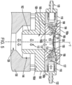
FIGs. 1-6C , anair channel 124 extends within thebody 106 for directing air. As best seen inFIG. 4 , theair channel 124 is formed betweensidewalls body 106 separated by adistance distance sidewalls 134, 136) decreases as theair channel 124 approaches theinner chamber 108, forming a narrowing slot. More particularly, thedistance 138a is greater at an end of theair channel 124 at theair intake 116, and thedistance 138b is less at an end of the air channel near theinner chamber 108. This causes air passing through theair channel 124 to narrow into the shape of a thin curtain (e.g., a sheet or film shape) as the air is directed out of theair channel 124 and into theinner chamber 108 and onto theprobe 102. Forming a thin curtain of air may be particularly helpful in drying theprobe 102 and directing the rinse liquid and waste downward toward thewaste outlet 132, since the narrow curtain results in a greater downward pressure on the waste, as compared to the pressure that would be applied were the air stream not narrowed. Further, to facilitate drying of theentire probe 102, theair channel 124 extends around the entire diameter of theinner chamber 108, providing air from multiple directions, e.g., all around and 360 degrees, around theprobe 102. In some implementations, thesidewalls air channel 124 extend into (seeextended walls FIG. 4 ) theinner chamber 108 and terminate in anarrow circumference 135 around the probe 102 (see e.g.FIG. 5 ). This can reduce the distance the air is required to travel to reach theprobe 102 after leaving theair channel 124. Further, the extended sidewalls 134a, 136a can act a splatter shield, blocking cleaning liquid that splatters off theprobe 102 during rinsing from exiting through theopening 110 of thebody 106. In other implementations, differently shaped channels and/or additional channels may also be used as an alternative to thechannels cleaning device 100. -
Flow arrows 140 inFIG. 3 depict an example path of air through thedevice 100. As shown, air reaches theintake 116, travels downward through theair channel 124, and contacts theprobe 102. The air then passes downwards through theinner chamber 108, towards thelower chamber 128 of thelower body 130. Thelower body 130 is connected to theupper body 106 by any mechanical means (e.g. screws) such that aseparation distance 142 between the lower andupper bodies separation distance 142 provides apath 144 for the air out of the cleaning device cleaning 100, and prevents pressure from building up within the cleaning device 100 (e.g. from excessive air buildup in the lower chamber 128), which could result in misting and splatter during the cleaning process. To help direct theair 140 along thepath 144, thelower body 130 includesinterior sidewalls 146 above thelower chamber 128 and thebody 106 includesexterior sidewalls 148, which define thepath 144, causing thepath 144 to initially slope upwards and away from the central axis y before extending directly upwards and parallel to a central vertical axis "y" of thedevice 100. After extending straight upwards, thepath 144 slopes horizontally away from the central axis y of theprobe 102. Further, since thepath 144 is defined by upwardly slopedwalls 146, thepath 144 can prevent rinse liquid or waste from exiting the through thepath 114. -
Flows arrows 150 inFIG. 5 depict an example path of the rinse liquid through thedevice 100. A pump and liquid reservoir (not shown herein) provide liquid to theliquid intake 118. From theliquid intake 118, the liquid flows through a number of separateliquid channels 126, which can be cylindrically shaped holes through thebody 106, and towards theprobe 102. The liquid approaches theprobe 102 at a vertically downwards angle (FIG. 6A ). The rinse liquid strikes theprobe 102 cleaning sample residue off the outer surface of theprobe 102. The liquid then passes into thelower chamber 128 and exits thedevice 100 through the waste outlet 132 (and thenozzle 133, if included). Notably, inFIGs. 3 and5 , theprobe 102 is omitted for ease of illustration of the air andwater flow - Referring to
FIGs. 6A-6C , thedevice 100 may include a plurality (e.g. three, four, five, or another number) of separateliquid channels 126, all individually connected to theliquid intake 118 for delivering liquid from theliquid intake 118 into theinner chamber 108. InFIGs. 6B-C , the example path of cleaning liquid after exiting thechannels 126 is shown vialiquid 152. The separateliquid channels 126 can be spaced equidistant from one another around the inner circumference 109 (FIG. 6A ) of theinner chamber 108 to cause the rinse liquid 152 to strike the probe 102 (omitted for ease of illustration of the rinse liquid 152) at different sides of the probe, helping cleaning of theentire probe 102. While theprobe 102 is omitted inFIG. 6A , the liquid 152 is shown as forming aring 153 at the center where the liquid 152 would normally strike theprobe 152 from multiple angles. Thechannels 126 can be cylindrically shaped, forming separate tunnels to direct jets ofliquid 152 at theprobe 102. This example arrangement may be effective for cleaning aprobe 102 within thecleaning device 100. However, other shapes and orientations ofliquid channels 126 may be used, such as cuboidal shaped or triangular shapedchannels 126. - Referring again to
FIGs. 1-6C , theair channel 124 is positioned above theliquid channels 126 with along the direction of the central axis y. This arrangement can allow the air to contact theprobe 102 location(s) above the location(s) where the rinse liquid 152 contacts the probe, moving the liquid 152 downward inside thedevice 100 and drying theprobe 102 as the probe is lifted upwards and out of theinner chamber 108. In this arrangement, thetip 158 of theprobe 102 can initially be lowered into theinner chamber 108, with thelower portion 154 of theprobe 102 eventually being positioned below thechannels 126. Thelower portion 154 of theprobe 102, below theliquid channels 126 will be rinsed by the liquid 152 during cleaning. In particular, once theprobe 102 has been lowered into the chamber 108 (e.g. as shown inFIG. 2 ), air and rinse liquid 152 can be provided through thechannels probe 102 can be lifted to rinse and dry thelower area 154 of the probe 102 (andpiercer 104 if included). Further, when theprobe 102 is within thecleaning device 100, an additional rinse line can be connected through the top end 156 (FIG. 2 ) of the probe 102 (theprobe 102 having a tubular structure) to provide rinse liquid to the interior of theprobe 102. The liquid within the interior of theprobe 102 can pass through theprobe 102, exiting from thetip 158 of theprobe 102 and passing to thewaste outlet 132. As theprobe 102 is lifted, the rinse liquid 152 from theliquid channels 126 comes into direct contact with the entirelower area 154 of theprobe 102 to clean the lower area. Similarly, air from theair channel 124 directly contacts theprobe 102 as it is lifted, drying the entirelower area 154 of theprobe 102 just after it is cleaned with the rinseliquid 152. Therefore, after theprobe 102 is seated within thecleaning device 100, theprobe 102 can be cleaned with a simple upward movement of theprobe 102. This avoids the need for any further manipulation of theprobe 102, resulting in a simple cleaning and drying sequence which can be carried out quickly to increase or to maximize throughput of the corresponding analyzer system. - In the example of
FIGs. 1- 6C , theupper body 106 of the cleaning device may be includemembers members 160a-160d can be formed separately and connected after formation, or one or more or the entire members can be formed as an integral part. Atop member 160a is in the shape of a plate which forms theopening 110 andseat 114 for theprobe 102. Theair channel 124 is formed between thetop member 160a and acentral exterior member 160c. For example, the bottom surface of thetop member 160a forms onesidewall 136 of the air channel 124 (FIG. 4 ). The opposingsidewall 134 of theair channel 124 is part of a surface of acentral exterior member 160c (FIG. 4 ). Additionally, theair intake 116, theliquid intake 118, and a beginning 127 of the liquid channels 126 (FIG. 5 ) proximate theintake 118 can be formed in thecentral exterior member 160c. The remainder of eachliquid channel 126 is formed in a centralinterior member 160b that is located between thecentral exterior member 160c and theinner chamber 108. The centralinterior member 160b has an open center, defining the top portion of theinner chamber 108. Alower member 160d located adjacent to themembers upper body 106. An inner opening within thelower member 160d defines the bottom of theinner chamber 108 leading into thelower body 130. Thelower member 160d includes a lowerprotruding end 162 having anouter diameter 163 smaller than an upper inner diameter 165 of the body 130 (FIG. 3 ). This allows thelower end 162 to be contained within thelower body 130. Theexterior sidewalls 148 of thelower end 162 define one side of theair path 144, andinterior sidewalls 146 of thelower body 130 form the opposing side of theair path 144. Thecentral exterior member 160c and centralinterior member 160b each include aflange interior member 160b between thecentral exterior member 160c and thelower member 160d. O-rings 168 are provided betweenadjacent members FIGs. 2-5 ). -
FIGs. 7-8 show another example implementation of aprobe cleaning device 700. Thedevice 700 is configured similarly to thedevice 100 shown inFIGs. 1-6C , except as otherwise shown and described herein. In particularly, thedevice 700 includesair channels 702 for directing air which are constructed or formed similar to theliquid channels 126 described above. Theair channels 702 can include a plurality (e.g. three, four, five, or another number) of separate tunnels, e.g., tube shaped tunnels, which direct air from anair intake 716 into theinner chamber 706 of thedevice 700, as indicated byair flow arrows 704. Theair channels 702 can be spaced, e.g., in equal distance, around the circumference of theinner chamber 706 to dry theprobe 708 from different directions. Theliquid channels 720 can include a plurality (e.g. three, four, five, or another number) of tunnels which are similarly formed and located, below theair channels 702, to provide liquid (e.g. arrows 736) to theprobe 708 for cleaning, asliquid channels 126. Waste liquid exits through thewaste nozzle 740, which includes an outer wall defining an opening, similar towaste nozzle 133, while excess air can exit throughair path 726 similar toair path 144. - The
upper body 710 of thecleaning device 700 includes twomembers Exterior member 712a defines theopening 714 for receiving theprobe 708, theintakes liquid channels Nozzles intakes interior member 712b dispersesair 704 and liquid 736 from thechannels inner chamber 706 to contact theprobe 708. A cylindrical opening in the center of theinner member 712b forms the top of theinner chamber 706. The lower portion of theinner chamber 706 is formed by a cylindrical opening in the bottom portion of theexterior member 712a. The top and bottom of thechamber 706 can have the same shape and size, e.g., the same diameter. The bottom portion of theexterior member 712a also forms a protrudinglower end 722, which defines sidewalls of theair path 726. The exterior andinterior members rings 738 on either side of both the upper andliquid channels exterior member 712a can be rigidly connected to thelower body 724 byrods 742 in theair path 726 while keeping the air path open. -
FIG. 9 shows an exampleprobe cleaning system 900 for use with the example probe cleaning devices described herein. Thesystem 900 includes acleaning device 902, which can include one of thecleaning devices cleaning device 902 has anair nozzle 904 andliquid nozzle 906 which connect thecleaning device 902 to air and liquid lines, respectively. Theair nozzle 904 is fed air by anair system 908, which can include a pump, pressurized air canister, or other device for delivering air via a connected air line. When theair system 908 is turned on, air from theair system 908 passes to theair nozzle 904 and into an air intake of thecleaning device 902 to dry theprobe 910 after theprobe 910 is lowered into thecleaning device 902. - A
degassing module 912 can prepare liquid as cleaning liquid for use within thesystem 900. Degassing can be used for precision fluids, but it should be understood that degassing, and therefore thedegassing module 912, are not required in all circumstances. For example, thedegassing module 912 is not needed when theprobe 902 is cleaned by rinsing with water. A rinsebottle 914 within the degassing module 912 (or separate, if nodegassing module 912 is used) includes a liquid, such as deionized water. Apump 916 transfers liquid from the rinsebottle 914, through acheck valve 915 and to a degasser 918 (if included), which allows excess gas to bleed off as the liquid passes through. Some liquid can be circulated back to the rinsebottle 914 to create a holding loop for precision fluidics, if necessary. However, for cleaning with a water rinse, no recirculation back to the rinsebottle 914 is necessary. The liquid is then sufficient for use as a cleaning liquid. When thedegasser 918 is used, some additional water evaporates and transfers thought the degassing membrane, being pulled in by thevacuum pump 941 to then be ejected to awaste container 940. - The cleaning liquid exits the
degassing module 912 and is split between twoseparate lines pump 924 on thefirst line 920 is operable to direct the cleaning liquid through acheck valve 926 and to theliquid nozzle 906 of thecleaning device 902. Apump 928 on thesecond line 922 is operable to direct cleaning liquid to asyringe pump 932 connected to theprobe 910. When theprobe 910 is placed within thecleaning device 902, thesyringe pump 932 is operable to pump cleaning liquid into the interior of theprobe 910 for cleaning. Avalve 943 on theprobe 910 can be opened to allow cleaning liquid within the interior of theprobe 910 to drain through theprobe tip 934. After cleaning theprobe 910, all cleaning liquid and any waste cleaned off theprobe 910 passes to awaste outlet 936 at the bottom of thecleaning device 902. Awaste line 938 directs the liquid and waste mixture to thewaste container 940 for storage and disposal. It is then ejected from the exit of the vacuum pump and sent to waste. - In general, the
cleaning system 900 can remain connected until a probe is ready to be cleaned. Once the probe is ready, thesyringe pump 932 can be connected to theprobe 910 manually, or automatically via the robotic system of the analyzer. The robotic system of the analyzer can then move theprobe 910 for cleaning, as described herein. -
FIG. 10 shows operations included in an example method for cleaning a probe using a cleaning device, such as thecleaning devices method 1000 relates to cleaning a probe that includes a surrounding piercer within a cleaning device. However, it should be understood that probes without piercers may also be cleaned using the systems and methods described herein. In this example, the method starts, atoperation 1001, after the probe and piercer have been used for sampling and require cleaning. The probe and piercer (or just probe, if no piercer is included) are then lowered through the upper opening of a cleaning device, atoperation 1002. For example, initially, the foot of the probe can be positioned above the top of the cleaning device. A valve on the probe is switched to bypass to allow liquid to flow through the probe (e.g., as shown fromvalve 943 ofFIG. 9 ). The probe is then lowered further such that the foot of the probe is positioned within the seat of the cleaning device. Alternatively, the bypass valve can be switched on after the probe is lowered. The probe and the piercer are on independent motion axes, allowing each to independently extend from the other for cleaning. Therefore, once the foot is within the seat, the probe is extended from the piercer and into the inner chamber (e.g.inner chamber 108 andlower chamber 128 ofFIG. 2 , for example). - At
operation 1004, an interior rinse is performed. A pump connected to a cleaning liquid reservoir can deliver liquid to the interior of the probe for cleaning (e.g., viabypass valve 943 ofFIG. 9 ). The liquid rinses the interior of the probe, passing through the open bypass valve and into the inner chamber of the cleaning device. Next, an exterior rinse is performed atoperation 1006. During the exterior rinse, a cleaning liquid is delivered from a liquid reservoir, e.g., using a pump, to the liquid intake (e.g.,intake 118 ofFIG. 3 ) of the cleaning device, through the liquid channels (e.g.,liquid channels 126 ofFIGs. 5-6C ) and to the exterior of the probe and piercer for cleaning. Waste liquid running off the probe can go through the waste outlet 132 (e.g.FIGs. 2-3 ) to a waste container. In some implementations, theoperations operation 1006 can be performed before theoperation 1004. - At
operation 1008, an air system connected to the air intake is then turned on. Various air systems can be used as part of the system. For example, the air system can include an air pump connected to the air intake of the cleaning device which can be turned on to provide air. Alternatively, a transmission line connected between an air source (e.g. a pressurized air canister) and the air intake may include a valve which can be turned to an open position to allow pressured air to flow through the air intake. The air can be turned on while water rinsing is still in progress to rinse and dry simultaneously. Once the air system is turned on, air passes through the air intake (e.g.,air intake 116 ofFIGs. 2-3 ) into the air channel (e.g. channel 124 ofFIGs. 2-5 ) of the cleaning device to the exterior of the probe to move the cleaning liquid downwards towards the waste outlet. - At
operation 1010, the probe and piercer are then retracted out of the cleaning device and washed during the process of retraction. This can be carried out by first retracting the piercer into the foot. As the piercer is retracted, the lower region of the piercer will come in direct contact with the liquid from the exterior rinse. Further, just after contact with the cleaning liquid, the exterior will be contacted by the air jets or curtains, drying the piercer before the piercer has been completely removed from the cleaning device. The probe can then be lifted to a position just above the air and water channels, cleaning the probe as it is raised. The inner rinse is then turned off, (e.g., by closingbypass valve 943 ofFIG. 9 ), atoperation 1012, stopping the delivery of the inner rinse liquid before the probe has been completely removed from the cleaning device. Once the inner rinse is turned off, the syringe bypass valve can then be closed atoperation 1014. Atoperation 1016, the outer rinse is turned off. The probe and piercer are then removed from the cleaning device, atoperation 1018, and the air system is turned off atoperation 1020. Notably, in some cases, the outer rinse can be turned off (i.e. operation 1016), stopping the delivery of the outer rinse liquid, after removal of the probe and piercer atoperation 1018. The probe and piercer have then been effectively cleaned and dried, and the method ends atoperation 1022. The total time required to complete a cleaning (i.e. to rinse and dry the probe and piercer, if included) is determined on a case by case basis, depending on the carryover risk of materials. Overall, themethod 1000 allows the probe and piercer to be dried quickly by simply lowering the probe and piercer into the cleaning device, and then raising the probe and piercer directly out of the cleaning device, without the need to rotate the probe and piercer or place them in a separate device. - All orientations and arrangements of the components shown herein are used by way of example only. Further, it will be appreciated by those of ordinary skill in the pertinent art that the functions of several elements may, in alternative implementations, be carried out by fewer elements or a single element. Similarly, in some implementations, any functional element may perform fewer, or different, operations than those described with respect to the illustrated implementation. Also, functional elements shown as distinct for purposes of illustration may be incorporated within other functional elements in a particular implementation.
- Like reference numerals are used herein to denote like parts. Further, words denoting orientation such as "upper", "lower", "distal", and "proximate" are merely used to help describe the location of components with respect to one another. For example, an "upper" surface of a part is merely meant to describe a surface that is separate from the "lower" surface of that same part. No words denoting orientation are used to describe an absolute orientation (i.e. where an "upper" part must always at a higher elevation).
- While the subject technology has been described with respect to preferred implementations, those skilled in the art will readily appreciate that various changes and/or modifications can be made to the subject technology.
- Elements of different implementations described may be combined to form other implementations not specifically set forth previously. Elements may be left out of the systems described previously without adversely affecting their operation or the operation of the system in general. Furthermore, various separate elements may be combined into one or more individual elements to perform the functions described in this specification.
Claims (14)
- A cleaning device (100) for cleaning a probe (102), comprising:an upper body (106) defining an inner chamber (108), the upper body (106) comprising an opening (110) proximate an upper end of the cleaning device (100), the opening (110) allowing the probe (102) to enter the inner chamber (108);an air intake (116) connected to at least one air channel (124) formed within the upper body (106), the at least one air channel (124) being configured to allow air from the air intake (116) to flow into the inner chamber (108);a liquid intake (118) connected to at least one liquid channel (126) formed within the upper body (106), the at least one liquid channel being configured to allow liquid from the liquid intake (118) to flow into the inner chamber (108);a waste outlet (132);a lower body (130) mechanically connected to the upper body (106), wherein the lower body (130) is positioned between the upper body (106) and the waste outlet (132), the lower body (130) defining a lower chamber (128) around an axis; andan air path (144) provided by a separation distance between the upper body (106) and the lower body (130) for air to exit the cleaning device.
- The cleaning device (100) of claim 1, wherein the waste outlet (132) is proximate a lower end of the cleaning device (100).
- The cleaning device (100) according to any one of the preceding claims, wherein the at least one air channel (124) is configured such that air flows towards a probe placed in the device (100) at a vertically downward angle towards a tip of the probe, wherein the at least one air channel (124) is in particular positioned vertically above the at least one liquid channel (126).
- The cleaning device (100) according to any one of the preceding claims, wherein the at least one air channel (124) is a single air channel extending around a circumference of the inner chamber (108).
- The cleaning device (100) according to any one of the preceding claims, wherein the at least one air channel (124) is a single air channel and formed by a distance (138a, 138b) between opposing sidewalls (134, 136), the distance including a first distance between the opposing sidewalls (134, 136) at a first end of the air channel at the inner chamber (108), the distance further including a second distance being at a second end of the air channel at the air intake (116), the first distance being less than the second distance, wherein the opposing sidewalls (134, 136) in particular extend into the inner chamber (108).
- The cleaning device (100) according to any one of the preceding claims, wherein:the at least one air channel (124) comprises a plurality of separate air channels, each air channel forming a cylindrical tunnel through the upper body (106) and into the inner chamber (108); andthe at least one liquid channel (126) comprises a plurality of separate liquid channels, each liquid channel forming a cylindrical tunnel through the upper body (106) and into the inner chamber (108).
- The cleaning device (100) of claim 6, wherein the separate air channels are spaced around a circumference of the inner chamber (108).
- The cleaning device (100) of claim 6 or claim 7, wherein the separate liquid channels are spaced around the circumference of the inner chamber (108).
- A method of cleaning a probe (102) using a cleaning device (100) comprising a lower body (130) mechanically connected to an upper body (106) and an air path (144) provided by a separation distance between the upper body (106) and the lower body (130) for air to exit the cleaning device, wherein the lower body (130) is positioned between the upper body (106) and a waste outlet (132), the lower body (130) defining a lower chamber (128) around an axis, the upper body (106) defining an inner chamber (108), the upper body (106) comprising an opening (110) proximate an upper end of the cleaning device (100), the opening (110) allowing the probe (102) to enter the inner chamber (108), wherein an air intake (116) is connected to at least one air channel (124) formed within the upper body (106), the at least one air channel (124) being configured to allow air from the air intake (116) to flow into the inner chamber (108), the method comprising:placing at least a part of the probe (102) into the inner chamber (108) of the cleaning device (100);directing air from the air intake (116) and through the air channel (124) of the cleaning device (100) and towards the probe (102), anddirecting a liquid from a liquid intake (118) through a plurality of liquid channels (126) of the cleaning device (100) and towards the probe (102) at a position vertically below the air channel (124).
- The method of claim 9, wherein the probe (102) is within a piercer (104), further comprising:inserting the probe (102) and piercer (104) through the opening (110) and into the chamber (108); andextending the probe (102) from the piercer (104);delivering a first liquid into the probe (102) such that the first liquid passes through the probe (102) and into a waste outlet (132) proximate a lower end of the cleaning device (100);turning on an air system of the cleaning device (100) to pass air through the air intake (116) and the at least one air channel (124) into the inner chamber (108);delivering a second liquid through the liquid intake (118) and the at least one liquid channel (126) into the inner chamber (108);retracting the probe (102) into the piercer (104);lifting the probe (102) to a position just above the air channel (124) and stopping delivery of the first liquid into the probe (102);lifting the probe (102) and piercer (104) out of the cleaning device (100); andafter lifting the probe (102) and piercer (104), turning off the air system and stopping the delivery of the second liquid into the inner chamber (108).
- The method of claim 9, further comprising;delivering a first liquid into the probe (102) such that the first liquid passes through the probe (102) and into a waste outlet (132) proximate a lower end of the cleaning device (100);turning on an air system of the cleaning device (100) to pass air through the air intake (116) and the at least one air channel (124) into the inner chamber (108);delivering a second liquid through the liquid intake (118) and the at least one liquid channel (126) into the inner chamber (108);stopping delivery of the first liquid into the probe (102);lifting the probe (102) out of the cleaning device (100); andafter lifting the probe (102), turning off the air system and stopping the delivery of the second liquid into the inner chamber (108).
- The method of claim 11, wherein, during the step of passing air through the air intake (116) and the at least one air channel (124) into the inner chamber (108), the air is passed into the inner chamber (108) at a vertically downward angle.
- The method of claim 11 or claim 12, wherein, during the step of passing air through the air intake (116) and the at least one air channel (124) into the inner chamber (108), the air is passed through the at least one air channel (124) in an air stream such that the air stream narrows as it approaches the inner chamber (108).
- The method of claim 9, further comprising:
after placing at least a part of the probe (102) into a chamber (108) of the cleaning device (100):delivering a first liquid into the probe (102) such that the first liquid passes through the probe (102) and into a waste outlet (132) proximate a lower end of the cleaning device (100);turning on an air system of the cleaning device (100) to pass air through the air intake (116) and the at least one air channel (124) into the inner chamber (108);delivering a second liquid through the liquid intake (118) and the at least one liquid channel (126) into the inner chamber (108);stopping delivery of the first liquid into the probe (102);turning off the air system;stopping the delivery of the second liquid into the inner chamber (108); andlifting the probe out of the cleaning device (100).
Applications Claiming Priority (1)
| Application Number | Priority Date | Filing Date | Title |
|---|---|---|---|
| US17/390,343 US11958084B2 (en) | 2021-07-30 | 2021-07-30 | System and method for cleaning an analyzer probe |
Publications (2)
| Publication Number | Publication Date |
|---|---|
| EP4124866A1 EP4124866A1 (en) | 2023-02-01 |
| EP4124866B1 true EP4124866B1 (en) | 2025-01-22 |
Family
ID=82701726
Family Applications (1)
| Application Number | Title | Priority Date | Filing Date |
|---|---|---|---|
| EP22186417.6A Active EP4124866B1 (en) | 2021-07-30 | 2022-07-22 | System and method for cleaning an analyzer probe |
Country Status (3)
| Country | Link |
|---|---|
| US (1) | US11958084B2 (en) |
| EP (1) | EP4124866B1 (en) |
| CN (1) | CN115672845B (en) |
Families Citing this family (3)
| Publication number | Priority date | Publication date | Assignee | Title |
|---|---|---|---|---|
| US20240295425A1 (en) * | 2023-03-02 | 2024-09-05 | Illinois Tool Works Inc. | Injection needle blowoff apparatus and injection testing systems |
| CN116858783B (en) * | 2023-09-04 | 2023-11-14 | 四川格林泰科生物科技有限公司 | Full-automatic blood analyzer |
| CN117161012A (en) * | 2023-09-21 | 2023-12-05 | 卡秋(江苏)生物科技有限公司 | Device for cleaning inner and outer walls of liquid suction needle |
Citations (1)
| Publication number | Priority date | Publication date | Assignee | Title |
|---|---|---|---|---|
| WO2011062982A1 (en) * | 2009-11-20 | 2011-05-26 | Siemens Healthcare Diagnostics Inc. | Apparatus, systems, and methods adapted to rinse and dry clinical analyzer sample probes |
Family Cites Families (10)
| Publication number | Priority date | Publication date | Assignee | Title |
|---|---|---|---|---|
| JPS5848836A (en) | 1981-09-18 | 1983-03-22 | Toa Medical Electronics Co Ltd | Optical type automatic analyzing and measuring device |
| JPS62242858A (en) | 1986-04-15 | 1987-10-23 | Nippon Tectron Co Ltd | Cleaning device for probe |
| JP5449967B2 (en) | 2009-10-05 | 2014-03-19 | 日立アロカメディカル株式会社 | Nozzle cleaning unit |
| CN201815510U (en) * | 2010-09-14 | 2011-05-04 | 浙江鸿森机械有限公司 | Cleaning device |
| JP2013134142A (en) | 2011-12-26 | 2013-07-08 | Hitachi High-Technologies Corp | Automatic analyzer |
| US9829498B2 (en) | 2015-04-22 | 2017-11-28 | Shimadzu Corporation | Sampling device |
| FR3039113B1 (en) * | 2015-07-22 | 2017-07-28 | Valeo Systemes Dessuyage | DEVICE FOR CLEANING A SENSOR FOR A MOTOR VEHICLE |
| EP3438674B1 (en) * | 2017-08-01 | 2022-06-22 | Euroimmun Medizinische Labordiagnostika AG | Method and device for cleaning pippeting tips |
| CN109772790A (en) * | 2019-01-24 | 2019-05-21 | 广州清新环保科技有限公司 | A central air-conditioning cabinet cleaning device |
| DE102020000018A1 (en) * | 2020-01-02 | 2021-07-08 | Jürgen von der Ohe | Method and device for manufacturing a cryogenically-acting blasting agent, as well as method and device for cleaning components with the cryogenically-mechanically acting blasting agent |
-
2021
- 2021-07-30 US US17/390,343 patent/US11958084B2/en active Active
-
2022
- 2022-07-22 EP EP22186417.6A patent/EP4124866B1/en active Active
- 2022-08-01 CN CN202210919804.6A patent/CN115672845B/en active Active
Patent Citations (1)
| Publication number | Priority date | Publication date | Assignee | Title |
|---|---|---|---|---|
| WO2011062982A1 (en) * | 2009-11-20 | 2011-05-26 | Siemens Healthcare Diagnostics Inc. | Apparatus, systems, and methods adapted to rinse and dry clinical analyzer sample probes |
Also Published As
| Publication number | Publication date |
|---|---|
| US20230033049A1 (en) | 2023-02-02 |
| EP4124866A1 (en) | 2023-02-01 |
| CN115672845B (en) | 2025-09-16 |
| CN115672845A (en) | 2023-02-03 |
| US11958084B2 (en) | 2024-04-16 |
Similar Documents
| Publication | Publication Date | Title |
|---|---|---|
| EP4124866A1 (en) | System and method for cleaning an analyzer probe | |
| US10690690B2 (en) | Automatic analyser and method | |
| KR101562139B1 (en) | Substrate processing apparatus and substrate processing method | |
| CN102630190B (en) | Be suitable for equipment, the system and method for flushing and dry clinical analysers sample probe | |
| US5186192A (en) | Apparatus for cleaning silicon wafer | |
| CN104903729B (en) | Automatic analysing apparatus | |
| CN104024868A (en) | Automatic analysis device | |
| JPH06222065A (en) | Device and method for cleaning fluid probe | |
| KR101210295B1 (en) | Apparatus for analyzing substrate contamination and method for analyzing wafer contamination using the same | |
| CN109070148B (en) | Probe cleaning station for analytical instruments | |
| JPS62242858A (en) | Cleaning device for probe | |
| US20240359201A1 (en) | Dispenser device, centrifuge comprising such a dispenser device, and method for cleaning dispenser nozzles | |
| CN102610488A (en) | Liquid processing apparatus and liquid processing method | |
| US20190049477A1 (en) | Automatic analyzer and cleaning method | |
| KR102485609B1 (en) | Apparatus for automatic sampling | |
| JP5954114B2 (en) | Sampling device | |
| CN212060287U (en) | Automatic liquid distribution system | |
| US20090032065A1 (en) | Syringe wash station for analytical applications | |
| US12360132B2 (en) | Automatic analyzer | |
| US9829498B2 (en) | Sampling device | |
| JP4385935B2 (en) | Automatic sample injection device | |
| KR102598307B1 (en) | Coupler with Integrated Dip Tube and Coupling System for Drum Container Including the Same | |
| US12174210B2 (en) | Automated analyzer and cleaning method | |
| CN120883061A (en) | Probe Cleaning System and Method | |
| HK1170980B (en) | Apparatus, systems, and methods adapted to rinse and dry clinical analyzer sample probes |
Legal Events
| Date | Code | Title | Description |
|---|---|---|---|
| PUAI | Public reference made under article 153(3) epc to a published international application that has entered the european phase |
Free format text: ORIGINAL CODE: 0009012 |
|
| STAA | Information on the status of an ep patent application or granted ep patent |
Free format text: STATUS: THE APPLICATION HAS BEEN PUBLISHED |
|
| AK | Designated contracting states |
Kind code of ref document: A1 Designated state(s): AL AT BE BG CH CY CZ DE DK EE ES FI FR GB GR HR HU IE IS IT LI LT LU LV MC MK MT NL NO PL PT RO RS SE SI SK SM TR |
|
| STAA | Information on the status of an ep patent application or granted ep patent |
Free format text: STATUS: REQUEST FOR EXAMINATION WAS MADE |
|
| 17P | Request for examination filed |
Effective date: 20230728 |
|
| RBV | Designated contracting states (corrected) |
Designated state(s): AL AT BE BG CH CY CZ DE DK EE ES FI FR GB GR HR HU IE IS IT LI LT LU LV MC MK MT NL NO PL PT RO RS SE SI SK SM TR |
|
| GRAP | Despatch of communication of intention to grant a patent |
Free format text: ORIGINAL CODE: EPIDOSNIGR1 |
|
| STAA | Information on the status of an ep patent application or granted ep patent |
Free format text: STATUS: GRANT OF PATENT IS INTENDED |
|
| INTG | Intention to grant announced |
Effective date: 20240911 |
|
| GRAS | Grant fee paid |
Free format text: ORIGINAL CODE: EPIDOSNIGR3 |
|
| GRAA | (expected) grant |
Free format text: ORIGINAL CODE: 0009210 |
|
| STAA | Information on the status of an ep patent application or granted ep patent |
Free format text: STATUS: THE PATENT HAS BEEN GRANTED |
|
| AK | Designated contracting states |
Kind code of ref document: B1 Designated state(s): AL AT BE BG CH CY CZ DE DK EE ES FI FR GB GR HR HU IE IS IT LI LT LU LV MC MK MT NL NO PL PT RO RS SE SI SK SM TR |
|
| REG | Reference to a national code |
Ref country code: GB Ref legal event code: FG4D |
|
| REG | Reference to a national code |
Ref country code: CH Ref legal event code: EP |
|
| REG | Reference to a national code |
Ref country code: IE Ref legal event code: FG4D |
|
| REG | Reference to a national code |
Ref country code: DE Ref legal event code: R096 Ref document number: 602022009746 Country of ref document: DE |
|
| REG | Reference to a national code |
Ref country code: NL Ref legal event code: MP Effective date: 20250122 |
|
| PG25 | Lapsed in a contracting state [announced via postgrant information from national office to epo] |
Ref country code: NL Free format text: LAPSE BECAUSE OF FAILURE TO SUBMIT A TRANSLATION OF THE DESCRIPTION OR TO PAY THE FEE WITHIN THE PRESCRIBED TIME-LIMIT Effective date: 20250122 |
|
| PG25 | Lapsed in a contracting state [announced via postgrant information from national office to epo] |
Ref country code: RS Free format text: LAPSE BECAUSE OF FAILURE TO SUBMIT A TRANSLATION OF THE DESCRIPTION OR TO PAY THE FEE WITHIN THE PRESCRIBED TIME-LIMIT Effective date: 20250422 |
|
| PG25 | Lapsed in a contracting state [announced via postgrant information from national office to epo] |
Ref country code: FI Free format text: LAPSE BECAUSE OF FAILURE TO SUBMIT A TRANSLATION OF THE DESCRIPTION OR TO PAY THE FEE WITHIN THE PRESCRIBED TIME-LIMIT Effective date: 20250122 |
|
| PG25 | Lapsed in a contracting state [announced via postgrant information from national office to epo] |
Ref country code: PL Free format text: LAPSE BECAUSE OF FAILURE TO SUBMIT A TRANSLATION OF THE DESCRIPTION OR TO PAY THE FEE WITHIN THE PRESCRIBED TIME-LIMIT Effective date: 20250122 |
|
| PG25 | Lapsed in a contracting state [announced via postgrant information from national office to epo] |
Ref country code: ES Free format text: LAPSE BECAUSE OF FAILURE TO SUBMIT A TRANSLATION OF THE DESCRIPTION OR TO PAY THE FEE WITHIN THE PRESCRIBED TIME-LIMIT Effective date: 20250122 |
|
| REG | Reference to a national code |
Ref country code: LT Ref legal event code: MG9D |
|
| PG25 | Lapsed in a contracting state [announced via postgrant information from national office to epo] |
Ref country code: IS Free format text: LAPSE BECAUSE OF FAILURE TO SUBMIT A TRANSLATION OF THE DESCRIPTION OR TO PAY THE FEE WITHIN THE PRESCRIBED TIME-LIMIT Effective date: 20250522 Ref country code: NO Free format text: LAPSE BECAUSE OF FAILURE TO SUBMIT A TRANSLATION OF THE DESCRIPTION OR TO PAY THE FEE WITHIN THE PRESCRIBED TIME-LIMIT Effective date: 20250422 |
|
| REG | Reference to a national code |
Ref country code: AT Ref legal event code: MK05 Ref document number: 1761838 Country of ref document: AT Kind code of ref document: T Effective date: 20250122 |
|
| PG25 | Lapsed in a contracting state [announced via postgrant information from national office to epo] |
Ref country code: HR Free format text: LAPSE BECAUSE OF FAILURE TO SUBMIT A TRANSLATION OF THE DESCRIPTION OR TO PAY THE FEE WITHIN THE PRESCRIBED TIME-LIMIT Effective date: 20250122 |
|
| PG25 | Lapsed in a contracting state [announced via postgrant information from national office to epo] |
Ref country code: PT Free format text: LAPSE BECAUSE OF FAILURE TO SUBMIT A TRANSLATION OF THE DESCRIPTION OR TO PAY THE FEE WITHIN THE PRESCRIBED TIME-LIMIT Effective date: 20250522 Ref country code: LV Free format text: LAPSE BECAUSE OF FAILURE TO SUBMIT A TRANSLATION OF THE DESCRIPTION OR TO PAY THE FEE WITHIN THE PRESCRIBED TIME-LIMIT Effective date: 20250122 |
|
| PG25 | Lapsed in a contracting state [announced via postgrant information from national office to epo] |
Ref country code: BG Free format text: LAPSE BECAUSE OF FAILURE TO SUBMIT A TRANSLATION OF THE DESCRIPTION OR TO PAY THE FEE WITHIN THE PRESCRIBED TIME-LIMIT Effective date: 20250122 Ref country code: GR Free format text: LAPSE BECAUSE OF FAILURE TO SUBMIT A TRANSLATION OF THE DESCRIPTION OR TO PAY THE FEE WITHIN THE PRESCRIBED TIME-LIMIT Effective date: 20250423 |
|
| PG25 | Lapsed in a contracting state [announced via postgrant information from national office to epo] |
Ref country code: AT Free format text: LAPSE BECAUSE OF FAILURE TO SUBMIT A TRANSLATION OF THE DESCRIPTION OR TO PAY THE FEE WITHIN THE PRESCRIBED TIME-LIMIT Effective date: 20250122 |
|
| PG25 | Lapsed in a contracting state [announced via postgrant information from national office to epo] |
Ref country code: SE Free format text: LAPSE BECAUSE OF FAILURE TO SUBMIT A TRANSLATION OF THE DESCRIPTION OR TO PAY THE FEE WITHIN THE PRESCRIBED TIME-LIMIT Effective date: 20250122 |
|
| PG25 | Lapsed in a contracting state [announced via postgrant information from national office to epo] |
Ref country code: SM Free format text: LAPSE BECAUSE OF FAILURE TO SUBMIT A TRANSLATION OF THE DESCRIPTION OR TO PAY THE FEE WITHIN THE PRESCRIBED TIME-LIMIT Effective date: 20250122 |
|
| PG25 | Lapsed in a contracting state [announced via postgrant information from national office to epo] |
Ref country code: DK Free format text: LAPSE BECAUSE OF FAILURE TO SUBMIT A TRANSLATION OF THE DESCRIPTION OR TO PAY THE FEE WITHIN THE PRESCRIBED TIME-LIMIT Effective date: 20250122 |
|
| PGFP | Annual fee paid to national office [announced via postgrant information from national office to epo] |
Ref country code: DE Payment date: 20250729 Year of fee payment: 4 |
|
| PGFP | Annual fee paid to national office [announced via postgrant information from national office to epo] |
Ref country code: IT Payment date: 20250731 Year of fee payment: 4 |
|
| PGFP | Annual fee paid to national office [announced via postgrant information from national office to epo] |
Ref country code: FR Payment date: 20250725 Year of fee payment: 4 |
|
| PGFP | Annual fee paid to national office [announced via postgrant information from national office to epo] |
Ref country code: CH Payment date: 20250801 Year of fee payment: 4 |
|
| PG25 | Lapsed in a contracting state [announced via postgrant information from national office to epo] |
Ref country code: EE Free format text: LAPSE BECAUSE OF FAILURE TO SUBMIT A TRANSLATION OF THE DESCRIPTION OR TO PAY THE FEE WITHIN THE PRESCRIBED TIME-LIMIT Effective date: 20250122 Ref country code: CZ Free format text: LAPSE BECAUSE OF FAILURE TO SUBMIT A TRANSLATION OF THE DESCRIPTION OR TO PAY THE FEE WITHIN THE PRESCRIBED TIME-LIMIT Effective date: 20250122 |
|
| REG | Reference to a national code |
Ref country code: DE Ref legal event code: R097 Ref document number: 602022009746 Country of ref document: DE |
|
| PG25 | Lapsed in a contracting state [announced via postgrant information from national office to epo] |
Ref country code: RO Free format text: LAPSE BECAUSE OF FAILURE TO SUBMIT A TRANSLATION OF THE DESCRIPTION OR TO PAY THE FEE WITHIN THE PRESCRIBED TIME-LIMIT Effective date: 20250122 |
|
| PG25 | Lapsed in a contracting state [announced via postgrant information from national office to epo] |
Ref country code: SK Free format text: LAPSE BECAUSE OF FAILURE TO SUBMIT A TRANSLATION OF THE DESCRIPTION OR TO PAY THE FEE WITHIN THE PRESCRIBED TIME-LIMIT Effective date: 20250122 |
|
| PLBE | No opposition filed within time limit |
Free format text: ORIGINAL CODE: 0009261 |
|
| STAA | Information on the status of an ep patent application or granted ep patent |
Free format text: STATUS: NO OPPOSITION FILED WITHIN TIME LIMIT |
|
| 26N | No opposition filed |
Effective date: 20251023 |
|
| PG25 | Lapsed in a contracting state [announced via postgrant information from national office to epo] |
Ref country code: LU Free format text: LAPSE BECAUSE OF NON-PAYMENT OF DUE FEES Effective date: 20250722 |
|
| REG | Reference to a national code |
Ref country code: BE Ref legal event code: MM Effective date: 20250731 |
|
| PG25 | Lapsed in a contracting state [announced via postgrant information from national office to epo] |
Ref country code: BE Free format text: LAPSE BECAUSE OF NON-PAYMENT OF DUE FEES Effective date: 20250731 |