EP4124820A1 - Mess- und datenintegrationssystem zur herstellung einer schusswaffe - Google Patents
Mess- und datenintegrationssystem zur herstellung einer schusswaffe Download PDFInfo
- Publication number
- EP4124820A1 EP4124820A1 EP20908927.5A EP20908927A EP4124820A1 EP 4124820 A1 EP4124820 A1 EP 4124820A1 EP 20908927 A EP20908927 A EP 20908927A EP 4124820 A1 EP4124820 A1 EP 4124820A1
- Authority
- EP
- European Patent Office
- Prior art keywords
- sensors
- firearm
- time
- projectile
- microprocessor
- Prior art date
- Legal status (The legal status is an assumption and is not a legal conclusion. Google has not performed a legal analysis and makes no representation as to the accuracy of the status listed.)
- Withdrawn
Links
- 238000005259 measurement Methods 0.000 title claims abstract description 34
- 230000010354 integration Effects 0.000 title 1
- 238000001514 detection method Methods 0.000 claims abstract description 15
- 238000004891 communication Methods 0.000 claims abstract description 11
- 230000006870 function Effects 0.000 claims description 6
- 238000007667 floating Methods 0.000 claims description 5
- 230000008878 coupling Effects 0.000 claims description 4
- 238000010168 coupling process Methods 0.000 claims description 4
- 238000005859 coupling reaction Methods 0.000 claims description 4
- 238000005070 sampling Methods 0.000 claims description 3
- 230000005355 Hall effect Effects 0.000 claims description 2
- 230000000295 complement effect Effects 0.000 claims description 2
- 230000005294 ferromagnetic effect Effects 0.000 claims description 2
- 239000004065 semiconductor Substances 0.000 claims description 2
- 230000004913 activation Effects 0.000 claims 1
- 238000012937 correction Methods 0.000 abstract description 15
- 230000005540 biological transmission Effects 0.000 abstract description 2
- 238000010586 diagram Methods 0.000 description 7
- 238000010304 firing Methods 0.000 description 7
- 238000010276 construction Methods 0.000 description 6
- 239000004417 polycarbonate Substances 0.000 description 5
- 230000008901 benefit Effects 0.000 description 4
- 230000005484 gravity Effects 0.000 description 4
- RLLPVAHGXHCWKJ-IEBWSBKVSA-N (3-phenoxyphenyl)methyl (1s,3s)-3-(2,2-dichloroethenyl)-2,2-dimethylcyclopropane-1-carboxylate Chemical compound CC1(C)[C@H](C=C(Cl)Cl)[C@@H]1C(=O)OCC1=CC=CC(OC=2C=CC=CC=2)=C1 RLLPVAHGXHCWKJ-IEBWSBKVSA-N 0.000 description 2
- 241001444201 Falco tinnunculus Species 0.000 description 2
- 230000003750 conditioning effect Effects 0.000 description 2
- 230000005291 magnetic effect Effects 0.000 description 2
- 239000004429 Calibre Substances 0.000 description 1
- 229910000831 Steel Inorganic materials 0.000 description 1
- 230000001133 acceleration Effects 0.000 description 1
- 238000004458 analytical method Methods 0.000 description 1
- 230000002238 attenuated effect Effects 0.000 description 1
- 239000000919 ceramic Substances 0.000 description 1
- 230000008859 change Effects 0.000 description 1
- 238000009826 distribution Methods 0.000 description 1
- 238000007688 edging Methods 0.000 description 1
- 230000007613 environmental effect Effects 0.000 description 1
- 230000002452 interceptive effect Effects 0.000 description 1
- 238000004519 manufacturing process Methods 0.000 description 1
- 239000000463 material Substances 0.000 description 1
- 239000002184 metal Substances 0.000 description 1
- 238000000034 method Methods 0.000 description 1
- 230000003287 optical effect Effects 0.000 description 1
- 230000002093 peripheral effect Effects 0.000 description 1
- 239000000843 powder Substances 0.000 description 1
- 230000008569 process Effects 0.000 description 1
- 239000003380 propellant Substances 0.000 description 1
- 238000009738 saturating Methods 0.000 description 1
- 230000000087 stabilizing effect Effects 0.000 description 1
- 238000007619 statistical method Methods 0.000 description 1
- 239000010959 steel Substances 0.000 description 1
- 238000003860 storage Methods 0.000 description 1
- 238000003466 welding Methods 0.000 description 1
- 238000004804 winding Methods 0.000 description 1
Images


Classifications
-
- F—MECHANICAL ENGINEERING; LIGHTING; HEATING; WEAPONS; BLASTING
- F41—WEAPONS
- F41G—WEAPON SIGHTS; AIMING
- F41G3/00—Aiming or laying means
- F41G3/14—Indirect aiming means
- F41G3/142—Indirect aiming means based on observation of a first shoot; using a simulated shoot
-
- F—MECHANICAL ENGINEERING; LIGHTING; HEATING; WEAPONS; BLASTING
- F41—WEAPONS
- F41A—FUNCTIONAL FEATURES OR DETAILS COMMON TO BOTH SMALLARMS AND ORDNANCE, e.g. CANNONS; MOUNTINGS FOR SMALLARMS OR ORDNANCE
- F41A21/00—Barrels; Gun tubes; Muzzle attachments; Barrel mounting means
- F41A21/32—Muzzle attachments or glands
-
- F—MECHANICAL ENGINEERING; LIGHTING; HEATING; WEAPONS; BLASTING
- F41—WEAPONS
- F41A—FUNCTIONAL FEATURES OR DETAILS COMMON TO BOTH SMALLARMS AND ORDNANCE, e.g. CANNONS; MOUNTINGS FOR SMALLARMS OR ORDNANCE
- F41A33/00—Adaptations for training; Gun simulators
-
- F—MECHANICAL ENGINEERING; LIGHTING; HEATING; WEAPONS; BLASTING
- F41—WEAPONS
- F41G—WEAPON SIGHTS; AIMING
- F41G3/00—Aiming or laying means
- F41G3/06—Aiming or laying means with rangefinder
-
- F—MECHANICAL ENGINEERING; LIGHTING; HEATING; WEAPONS; BLASTING
- F41—WEAPONS
- F41G—WEAPON SIGHTS; AIMING
- F41G3/00—Aiming or laying means
- F41G3/08—Aiming or laying means with means for compensating for speed, direction, temperature, pressure, or humidity of the atmosphere
-
- F—MECHANICAL ENGINEERING; LIGHTING; HEATING; WEAPONS; BLASTING
- F41—WEAPONS
- F41G—WEAPON SIGHTS; AIMING
- F41G3/00—Aiming or laying means
- F41G3/12—Aiming or laying means with means for compensating for muzzle velocity or powder temperature with means for compensating for gun vibrations
-
- F—MECHANICAL ENGINEERING; LIGHTING; HEATING; WEAPONS; BLASTING
- F41—WEAPONS
- F41A—FUNCTIONAL FEATURES OR DETAILS COMMON TO BOTH SMALLARMS AND ORDNANCE, e.g. CANNONS; MOUNTINGS FOR SMALLARMS OR ORDNANCE
- F41A21/00—Barrels; Gun tubes; Muzzle attachments; Barrel mounting means
- F41A21/32—Muzzle attachments or glands
- F41A21/325—Mountings for muzzle attachments
Definitions
- the present invention finds its field of application in a device capable of measuring the aerodynamic, atmospheric, tilt, time-of-flight variables and solving the equations making use of said variables predicting the trajectory of a following round fired by a firearm.
- this device is preferably used to solve the shooting equations of all types of long barrel weapons, such as firearms, shoulder weapons, support weapons, rifles, submachine guns, short handguns or any type of weapon that uses ballistic concepts in general.
- US patent 9,574,843 issued to the firm MAGNETOSPEED LLC teaches how to detect the deviation of the projectile issuing from a portable weapon (rifle).
- This patent shows how linking the muzzle of the weapon with a trajectory correction device consisting of a tubular piece (20) inside which a ballistic chronograph (21) is located (See Fig. 2 of this patent US 9,574,843 ) and a control circuit (22) with one or more windings (24) arranged at the outlet of this tubular piece.
- the velocity of the projectile obtained through the ballistic chronograph 2 is sent to the control circuit (22) wherein the appropriate impulse to impart to the projectile (25) is calculated.
- the pulse power supply (23) then discharges an appropriate amount of energy to the steering coils (24) whose magnetic fields impart a small amount of corrective kinetic energy to the projectile (25) as it passes through the steering coils (24) (with approximately a 10 ⁇ s to 30 ⁇ s time window) by adjusting the paths energizing one or more drive coils (24).
- the projectile velocity sensors (25) of the ballistic chronograph (21) are very close to the mouth of gun's barrel and practically the first sensor is very close to the second.
- no information is provided regarding the impact zone, trying a priori to correct the trajectory based on anemometric data fed to the control circuit.
- a sensor module (110) and a controller (116) are arranged at the mouth of the gun's barrel, but in an open configuration, that is, without the use of a tubular piece through which the speed of the projectile is measured.
- the sensor module (110) is made up of a pair of sensor coils (106, 108). On each of the sensor coils (106, 108) sequential voltages are produced which are transmitted to the controller (116) determining the speed of the projectile (104).
- An attenuated voltage is applied to a processor (300) containing an analogic comparator (340) to compare the voltage at a sensor signal jack and the threshold voltage (320). The voltage waves and their zero crossings are compared to determine the corrections to be imparted to the projectile by the magnetic field produced by the coils.
- the known in the art shooting solution devices are independent devices each one of them only reflecting a single data; as a consequence they fail to correct or predict point-of-impact (target) corrections, and these individual components cannot work together as a single device providing a ballistic programme providing point-of-impact fire correction or ballistic engine.
- Known trajectory correction devices do not have a programme or dedicated backup software enabling comprehensive shooting solutions.
- ballistic Doppler devices capable of following the trajectory of the projectile up to a distance of 500-700 meters and mainly applied to artillery shooting solutions are known on the market, but apart from its high cost, they cannot be applied in a practical and costs contained way to measure the deviation of the ballistic trajectory of small calibre firearm such as a rifle, while at the same time provide shooting solutions at a distance of up to 5,000 meters. Such result up to date is impossible to achieve with the traditional means known in the art.
- the object of the present invention is an integrated system capable of measuring variables and gathering data and parameters to achieve the firing solution, that is, to calculate the corrections to the firearm's aiming system to ensure the impact on the target of as subsequent round, measuring data obtained through a first round impact on a target, which includes in integral association:
- FIREARMS INSTRUMENTING SYSTEM INTEGRATING DISTINCT MEASUREMENTS THAT INFLUENCES THE BALISTIC TRAJECTORY AND ITS CORRESPONDING DATA RETRIEVAL characterized in that it includes in combination the following interlinked subsystems:
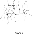
- Block diagram of Figure 1 depicts one of the possible schematic diagrams leading to the desired result as per this instant patent.
- figure reference (1) indicates a tubular piece, such as for example a flame arrester suppressor tube or compensator, linked to the end or muzzle of the barrel (2) of the weapon.
- connection of the tubular piece (1) to the gun barrel mouth (2) can be achieved basically in two ways.
- the first involves a fixed connection of the tubular part (1) to said barrel mouth (2) by means of complementary helical threads, sliders, clamps or magnets.
- two sensors (3, 4) are placed aligned along the trajectory of the projectile and separated or distanced the one from the other.
- an inclinometer (5) with two axes -x-, -z- is located.
- the second modality for linking the aforementioned tubular part (1) to the weapon is illustrated in Figure 5 .
- the barrel of the weapon (2) is observed wherein the tubular component (2) is not directly linked to the barrel mouth.
- the coupling end of (1) conveniently has a recess (24) into which the end of (2) is inserted, without being coupled.
- the tubular part (1) has at least one extension (25) for connection with, for example, a portion of a bipod (26) or another structure fixed to the weapon.
- This second fixing modality does not involve connecting the tubular piece directly with the gun's barrel, but rather it leaves same "floating", without its own natural resonance frequency interfering with the gun barrel resonance frequency.
- the barrel does not have any contact with the tubular structure carrying said sensors, hence the tubular structure can be open or closed, integrated with a flame suppressor, compensator, muzzle brake or suppressor.
- the signal (7) representative of the speed of the projectile and the signals -x-, -z- emitted by the inclinometer (5) enter a block (6) representing one of the many possible converter signal conditioning circuits A/D.
- the principle of measuring the speed of the projectile (8) (See Figure 2 ) at the muzzle is based on measuring the time it takes for the projectile to travel a known distance (D) (See Figure 6 ) between the two sensors (3, 4).
- the distance (D) preferably has a magnitude range between 70mm to 150mm.
- These sensors can have different operating principles, for example, by Hall effect, by reluctance variation, by ferro-magnetic effect, by induced currents, etc.
- the amplitude of the signal (7) generated by the two sensors is proportional to the height "H" measured between the bore line (9) and the active area of the sensor, so that both sensors (3, 4) must be at a height (H) such that its signal has the highest amplitude without saturating the limiting diode (10) (See Fig. 7 ) of the signal conditioning module (6).
- the passage of the projectile (8) over the active surface of a sensor (3, 4) is detected when the voltage generated between its two electrodes, expressed in volts, exceeds a threshold voltage (13) (See Figure Fig.8 ).
- the detector is the subsystem (6), enlarged in Figure 7 , and called “analogic comparator” and it presents a logic state change when the voltage at the sensor output exceeds the threshold.
- the threshold voltage is established by the low-pass filter (11) and the PWM pulse train (12) entering into (11).
- variable measurements starts with the detection of the projectile (8) in the sensor (3), interrupting its "Supervision” mode performed by the micro-processor (14) changing its state to "Measurement” mode.
- the microprocessor (14) stores in a memory a first time T1, obtained through its high-precision internal clock, and waits for the projectile (8) to be detected by the following sensor (4).
- the detection of the passage of the projectile through sensor (4) causes the micro-processor (14) to store a second time T2 in the memory exciting from the "Measurement” mode and entering into a "Transmission” mode.
- times T1 and T2 values are recorded in precision of millionths of a second.
- the timing diagram is shown at Figure 6 .
- the microprocessor (14) transmits the recorded information of both time values T1 and T2 to the software under Windows ® , Linux ® , OS or other known platforms environments through a wired or wireless interface.
- the system software which is preferably working under said Windows ® , Linux ® , OS or other environment, performs the quotient between the known distance D and the time difference T1-T2, taking advantage of the arithmetic capabilities in floating point processor running Windows ® , Linux ® , OS or others.
- the sensor calibration subsystem is of primary importance for the purposes of the present invention.
- the signal generated by the sensors is a function of the height H between the line (9) of the barrel bore and the said sensors active base (See Fig. 6 ).
- both sensors (3, 4) Due to imperfections in the coupling of the sensors (3, 4) to the weapon, it may happen that the sensors could be placed at different heights. If this height H Is found, the sensors will detect the passage of the projectile with different amplitudes, resulting in the error in the time measurement values as shown in Figure 8 . For the purposes of the present invention, it is mandatory that both sensors (3, 4) generate signs of equal amplitude detection in order to minimize the error in time measurement.
- An algorithm routine in the microprocessor (14) generates a 256 8-bit vector samples allowing to establishing two very important aspects in the accuracy of the meter: one of them is the absolute amplitude of the signal generated by the sensors and the other, measures the relative amplitude between both sensors.
- the same routine is in charge of sending the 256 data vector of to the application. Corrections in the coupling devices of the meter to the barrel or external stabilizing structures such as bipods, tripods, monopods, allows increasing the amplitude of the signal and equalize the amplitudes between the sensors in order to minimize the error in the time measurement.
- the purpose of the sensor calibration subsystem is to minimize the measurement error by correcting the height of the two sensors so that both read the same amplitude value. It works in conjunction with the "Sensor Calibration" subsystem, providing a graphical representation of the voltage as a function of the time of the signal in both sensors according to Figure 8 . In this figure, in the upper representation the time differential "d" is observed due to the variation of amplitudes between one sensor and the other, and in the lower Figure 8 the times correction when the amplitudes of both sensors are equal.
- the impact detection and time-of-flight measurement subsystem consists of two modules linked by RF in the free-use band of 2.4GHz or 433MHz.
- a module called Receiver Module (15) receives a message from a module called Impact Detection Transmitter Module (16) when it detects the impact of a projectile on the target (17).
- Impact detection is preferably, but not mandatory, by means of a piezoelectric ceramic fixed to the metal surface of the target. This sensor is located in the centre of gravity of the target so that the detection distance with said target is as short as possible.
- the measurement principle is based on the difference in speed between the projectile or bullet and the electromagnetic waves that make up the RF radio frequency, with the ratio of the speed of light to the speed of the bullet being 300,000 times.
- the detection signal travels from the transmitter module (16) to the receiver module (15) at the speed of Hertz waves, which is approximately 300,000 km/s.
- the meter detects the passage of a projectile over the sensor (3). At that moment, it starts a stopwatch with 125ns resolution (1/8,000,000 s). The projectile or bullet travels from the weapon (2) firing towards the target (17) (remote) at a typical speed of 1 km/s.
- the receiver module (15) is waiting for the transmitter module (16) to notify the detection of the impact of the projectile on the target (17).
- the receiver module (15) receives the message from the transmitter module (16) and stops the stopwatch which saves the time of flight magnitude, and by subtracting the fixed and measurable fractions of time, which are those associated with the time it takes for the sound from the impact zone on the target's material (17) until reaching the piezoelectric sensor (5km/s on steel, 5 times faster than the bullet).
- the chronometer gives the microprocessor (14) the value of the time of flight so that it sends it to the application under Windows, Linus, OS or other environments through the wired or wireless interface.
- the receiver module (15) is controlled by the microprocessor (14).
- the inclinometer subsystem (5) with its two axes -x-, -z- provides other variables that must be controlled to ensure a precise and predictable shot.
- the system incorporates an inclinometer (5) with two axes, -x-, -z- belonging to a MEMS (Micro Electro Mechanical System).
- MEMS Micro Electro Mechanical System
- the integrated semiconductor is linked to the printed circuit board housing the main electronics. The welding process of the MEMS to the plate ensures the total horizontality of the inclinometer with respect to the barrel bore.
- the -x- axis measures the inclination and the -z- axis the edging.
- the analogic magnitudes are converted to data by the analogic to digital converter contained in the micro-processor as shown in the block diagram of Fig. 1 . They are sent to the software under, for instance, Windows environment through the USB interface.
- the angle values are sent by the hardware unit at regular time intervals.
- the microprocessor subsystem (14) provides data manage, the use of all the resources usage and with a clock frequency calibrated at 20 MHz.
- the internal modules of communication send the data collected by wired or wireless interface. B to the application under Windows environment.
- the meteorological bases (18) and the Wi-Fi cameras (19) send their data to the Windows environment (20), and from which the data is sent to the cloud storage (21), or to the reporting printer (22) or to a remote desktop (23), or any combination of such or any other known peripherals.
- the system of the present invention incorporates a subsystem to communicate with the meteorological bases of the Kestrel, GeoTek, or similar type or of own manufacture, taking advantage of the BlueTooth communication contained in the tubular structure.
- the integrated system for the instrumentation of firearms of the invention needs to know the meteorological variables in order to allow the integrated ballistic engine to solve the trajectory equation.
- the system connects via Bluetooth or WiFi communication from the PC with the meteorological bases that have been arranged in the path of the projectile.
- the number of bases can be variable according to the amount of data the motor can handle and the distance from the target or the PC running the application.
- the meteorological bases measures the following variables: relative humidity, atmospheric pressure, temperature, magnitude and direction of the wind. These last two magnitudes are generally measured by the vane-anemometer assembly, which can be mechanical, 2D ultrasonic, or 3D ultrasonic.
- the well-known meteorological base provided under the Trademark Kestrel model 4500 is consulted by bluetooth delivers all the meteorological variables in a single data vector.
- the system of the present invention links its hardware with its software part by means of a wired or wireless interface link.
- the Windows, Linux, OS or other operating system detects the integrated system for the instrumentation of firearms of the invention and assigns it a virtual port, leaving it operative until the application under Windows environment, Linux, OS or others take control of the port.
- the system software comprises two very different codes, the first one is the microprocessor resident programme, written in a compatible language, very compact and efficient, in charge of detecting the sensors, carrying out the muzzle velocity measurement, measuring and converting the data delivered by the two-axis inclinometer, managing all impact detection and flight time measurement, from which the ballistic coefficient is derived, and perform sensor's calibration.
- the user interface presents in a single page the information necessary to analyse the performance of the shot in real time. On this main screen it is observed the muzzle velocity, all the statistical analysis of the shots, the angles of inclination and if the system is linked to a ballistic motor, it also gives the shooting solution in terms of the correction to be made to the aiming device coupled to the firearm (e.g., a scope) to ensure the impact of the projectile on the target.
- the aiming device coupled to the firearm (e.g., a scope) to ensure the impact of the projectile on the target.
- the application under Windows environment runs using the "Cores” and “Threads” of the processor to optimize the attention of the resources and the operations in floating point. Take advantage of the HD resolution of the screen to display the greatest amount of information in a useful and orderly way.
- the application also takes advantage of all the connectivity resources offered by the PC that runs it, the WiFi connection, BlueTooth, the Ethernet port, the infrared port and others, to connect cameras, rangefinders, GPS's, etc.
- This table gathers the statistical information of the variable measured with the system, providing the maximum, minimum, and average values and, above all, the standard variation, known as SD. All statistical values are recalculated for each shot, taking muzzle velocity as the main variable.
- the curve of velocity probability density is the velocity probability distribution curve, known as the Gaussian probability density and offer an immediate estimate of the performance of the rifle/ammunition set. It allows inferring the area probability density of impact.
- the system of the invention has an integrated ballistic motor, which can be summarized on the screen according to Figure 10, and by "ballistic motor” it is being understood as the set of equations to which variables such as: projectile speed, ballistic coefficient of the projectile, the atmospheric date, the distance to the target, the inclination, data those linked to the weapon, etc. will result in the "Shooting Solution”, as the prevailing data and final result of this invention, which is applied by means of the necessary corrections to the elevation and drift that must be given to the aiming system, whether they are optical, orthoptic, electronic, mechanical or of any kind, so that the following shot is accurate and precise on target.
- the interface with the ballistic motor is a vector of measured and stored data. Each time a shot is recorded, the system delivers the data vector to the ballistic engine to calculate the new shot solution. The vector in turn is stored with date and time in the non-volatile memory of the PC or sent to a cloud service to be later analysed.
- Non-volatile memory resources contained in the PC running under Windows, Linux, OS or other environment are used.
Landscapes
- Engineering & Computer Science (AREA)
- General Engineering & Computer Science (AREA)
- Aiming, Guidance, Guns With A Light Source, Armor, Camouflage, And Targets (AREA)
Applications Claiming Priority (1)
| Application Number | Priority Date | Filing Date | Title |
|---|---|---|---|
| PCT/IB2020/050037 WO2021136974A1 (es) | 2020-01-03 | 2020-01-03 | Sistema integrador de mediciones y datos para instrumentar un arma de fuego |
Publications (1)
| Publication Number | Publication Date |
|---|---|
| EP4124820A1 true EP4124820A1 (de) | 2023-02-01 |
Family
ID=76685960
Family Applications (1)
| Application Number | Title | Priority Date | Filing Date |
|---|---|---|---|
| EP20908927.5A Withdrawn EP4124820A1 (de) | 2020-01-03 | 2020-01-03 | Mess- und datenintegrationssystem zur herstellung einer schusswaffe |
Country Status (3)
| Country | Link |
|---|---|
| US (1) | US11898822B2 (de) |
| EP (1) | EP4124820A1 (de) |
| WO (1) | WO2021136974A1 (de) |
Families Citing this family (6)
| Publication number | Priority date | Publication date | Assignee | Title |
|---|---|---|---|---|
| US11898822B2 (en) * | 2020-01-03 | 2024-02-13 | Carlos Maria ORTEGA | Firearms instrumenting system integrating distinct measurements that influences the ballistic trajectory and its corresponding data retrieval |
| IL290443B2 (en) * | 2022-02-08 | 2025-02-01 | Smart Shooter Ltd | Systems and methods for restricting weapons to less lethal fire |
| US20240019229A1 (en) * | 2022-07-18 | 2024-01-18 | Michael Robert Christensen | Attachable Anemometer for Firearm |
| CN115307680A (zh) * | 2022-08-08 | 2022-11-08 | 南京理工大学 | 一种微型射击影响参数自动测量系统 |
| FR3154174B1 (fr) * | 2023-10-17 | 2025-10-31 | Ertc Tech | Un bouchon de tir intelligent |
| US12352533B1 (en) | 2024-04-30 | 2025-07-08 | Optex Systems, Inc. | Next shot compensation system for weapons |
Family Cites Families (8)
| Publication number | Priority date | Publication date | Assignee | Title |
|---|---|---|---|---|
| US20030082502A1 (en) * | 2001-10-29 | 2003-05-01 | Stender H. Robert | Digital target spotting system |
| US9709593B1 (en) * | 2011-09-28 | 2017-07-18 | Magnetospeed Llc | Apparatus for measuring velocities of projectiles launched from firearms |
| JP6032910B2 (ja) | 2012-03-22 | 2016-11-30 | 株式会社日立国際電気 | 発射弾数計測装置 |
| US9127910B2 (en) * | 2012-07-09 | 2015-09-08 | Torrey Pines Logic, Inc. | Crosswind speed measurement by optical measurement of scintillation |
| US9010002B2 (en) * | 2013-02-01 | 2015-04-21 | Liviu Popa-Simil | Method and accessory device to improve performances of ballistic throwers |
| US9574843B2 (en) * | 2014-02-27 | 2017-02-21 | Magnetospeed Llc | Apparatus for correcting trajectories of projectiles launched from firearms |
| US20160069643A1 (en) * | 2014-09-06 | 2016-03-10 | Philip Lyren | Weapon Targeting System |
| US11898822B2 (en) * | 2020-01-03 | 2024-02-13 | Carlos Maria ORTEGA | Firearms instrumenting system integrating distinct measurements that influences the ballistic trajectory and its corresponding data retrieval |
-
2020
- 2020-01-03 US US17/758,187 patent/US11898822B2/en active Active
- 2020-01-03 WO PCT/IB2020/050037 patent/WO2021136974A1/es not_active Ceased
- 2020-01-03 EP EP20908927.5A patent/EP4124820A1/de not_active Withdrawn
Also Published As
| Publication number | Publication date |
|---|---|
| US20230058539A1 (en) | 2023-02-23 |
| WO2021136974A1 (es) | 2021-07-08 |
| US11898822B2 (en) | 2024-02-13 |
Similar Documents
| Publication | Publication Date | Title |
|---|---|---|
| US11898822B2 (en) | Firearms instrumenting system integrating distinct measurements that influences the ballistic trajectory and its corresponding data retrieval | |
| US8172139B1 (en) | Ballistic ranging methods and systems for inclined shooting | |
| KR102756232B1 (ko) | 풍향 포착을 구비하는 시야 광학체 및 이를 이용하는 방법 | |
| US8757487B2 (en) | Optoelectronic digital apparatus for assisting an operator in determining the shooting attitude to be given to a hand-held grenade launcher so as to strike a moving target, and respective operation method | |
| EP2781875A2 (de) | Präzisionszielsystem für eine Waffe | |
| CN101512282A (zh) | 用于倾斜射击的弹道测距方法及系统 | |
| US9777992B2 (en) | Embedded cant indicator for rifles | |
| CN110162735B (zh) | 一种基于激光测距望远镜的弹道轨迹计算方法及系统 | |
| US20160258973A1 (en) | System for predicting exterior ballistics | |
| EP4500104A1 (de) | Benutzerschnittstelle für eine betrachtungsoptik mit windrichtungserfassung | |
| US5359920A (en) | Munition impact point indicator and automatic gun aimpoint correction system | |
| ITTV20100099A1 (it) | Apparecchio optoelettronico per assistere un operatore nella determinazione dell'assetto di tiro da impartire ad un lanciagranate portatile per colpire un target, e relativo metodo di funzionamento | |
| US20170350914A1 (en) | System and method for long-range ballistic calculation | |
| US12352533B1 (en) | Next shot compensation system for weapons | |
| RU2676301C1 (ru) | Способ стрельбы зенитными снарядами | |
| Hongxiao et al. | Research on the muzzle vibration displacement test method of large-caliber rifled gun based trinocular vision | |
| Liistro | External ballistics: projectile speed measurement techniques and possible applications | |
| CN115808105A (zh) | 基于连续多点的风速测量的弹道校准方法 | |
| CN107782333A (zh) | 卧式弹着点被动声定位装置的测前调试装置及调试方法 | |
| Beckman | The Elements of Firing Table Construction | |
| TR201800535A2 (tr) | Görerek atış yönlendirme sistemi |
Legal Events
| Date | Code | Title | Description |
|---|---|---|---|
| STAA | Information on the status of an ep patent application or granted ep patent |
Free format text: STATUS: THE INTERNATIONAL PUBLICATION HAS BEEN MADE |
|
| PUAI | Public reference made under article 153(3) epc to a published international application that has entered the european phase |
Free format text: ORIGINAL CODE: 0009012 |
|
| STAA | Information on the status of an ep patent application or granted ep patent |
Free format text: STATUS: REQUEST FOR EXAMINATION WAS MADE |
|
| 17P | Request for examination filed |
Effective date: 20220803 |
|
| AK | Designated contracting states |
Kind code of ref document: A1 Designated state(s): AL AT BE BG CH CY CZ DE DK EE ES FI FR GB GR HR HU IE IS IT LI LT LU LV MC MK MT NL NO PL PT RO RS SE SI SK SM TR |
|
| STAA | Information on the status of an ep patent application or granted ep patent |
Free format text: STATUS: THE APPLICATION IS DEEMED TO BE WITHDRAWN |
|
| 18D | Application deemed to be withdrawn |
Effective date: 20230801 |