EP4124739B1 - Blendenpaket für kompressor-entlüftungsventil - Google Patents
Blendenpaket für kompressor-entlüftungsventil Download PDFInfo
- Publication number
- EP4124739B1 EP4124739B1 EP22188162.6A EP22188162A EP4124739B1 EP 4124739 B1 EP4124739 B1 EP 4124739B1 EP 22188162 A EP22188162 A EP 22188162A EP 4124739 B1 EP4124739 B1 EP 4124739B1
- Authority
- EP
- European Patent Office
- Prior art keywords
- diffusion chamber
- orifice
- bleed valve
- passage
- pack
- Prior art date
- Legal status (The legal status is an assumption and is not a legal conclusion. Google has not performed a legal analysis and makes no representation as to the accuracy of the status listed.)
- Active
Links
Images


Classifications
-
- F—MECHANICAL ENGINEERING; LIGHTING; HEATING; WEAPONS; BLASTING
- F04—POSITIVE - DISPLACEMENT MACHINES FOR LIQUIDS; PUMPS FOR LIQUIDS OR ELASTIC FLUIDS
- F04D—NON-POSITIVE-DISPLACEMENT PUMPS
- F04D25/00—Pumping installations or systems
- F04D25/02—Units comprising pumps and their driving means
- F04D25/04—Units comprising pumps and their driving means the pump being fluid-driven
-
- F—MECHANICAL ENGINEERING; LIGHTING; HEATING; WEAPONS; BLASTING
- F02—COMBUSTION ENGINES; HOT-GAS OR COMBUSTION-PRODUCT ENGINE PLANTS
- F02C—GAS-TURBINE PLANTS; AIR INTAKES FOR JET-PROPULSION PLANTS; CONTROLLING FUEL SUPPLY IN AIR-BREATHING JET-PROPULSION PLANTS
- F02C6/00—Plural gas-turbine plants; Combinations of gas-turbine plants with other apparatus; Adaptations of gas-turbine plants for special use
- F02C6/04—Gas-turbine plants providing heated or pressurised working fluid for other apparatus, e.g. without mechanical power output
- F02C6/06—Gas-turbine plants providing heated or pressurised working fluid for other apparatus, e.g. without mechanical power output providing compressed gas
- F02C6/08—Gas-turbine plants providing heated or pressurised working fluid for other apparatus, e.g. without mechanical power output providing compressed gas the gas being bled from the gas-turbine compressor
-
- F—MECHANICAL ENGINEERING; LIGHTING; HEATING; WEAPONS; BLASTING
- F02—COMBUSTION ENGINES; HOT-GAS OR COMBUSTION-PRODUCT ENGINE PLANTS
- F02C—GAS-TURBINE PLANTS; AIR INTAKES FOR JET-PROPULSION PLANTS; CONTROLLING FUEL SUPPLY IN AIR-BREATHING JET-PROPULSION PLANTS
- F02C9/00—Controlling gas-turbine plants; Controlling fuel supply in air- breathing jet-propulsion plants
- F02C9/16—Control of working fluid flow
- F02C9/18—Control of working fluid flow by bleeding, bypassing or acting on variable working fluid interconnections between turbines or compressors or their stages
-
- F—MECHANICAL ENGINEERING; LIGHTING; HEATING; WEAPONS; BLASTING
- F04—POSITIVE - DISPLACEMENT MACHINES FOR LIQUIDS; PUMPS FOR LIQUIDS OR ELASTIC FLUIDS
- F04D—NON-POSITIVE-DISPLACEMENT PUMPS
- F04D27/00—Control, e.g. regulation, of pumps, pumping installations or pumping systems specially adapted for elastic fluids
- F04D27/02—Surge control
- F04D27/0207—Surge control by bleeding, bypassing or recycling fluids
- F04D27/0215—Arrangements therefor, e.g. bleed or by-pass valves
-
- F—MECHANICAL ENGINEERING; LIGHTING; HEATING; WEAPONS; BLASTING
- F04—POSITIVE - DISPLACEMENT MACHINES FOR LIQUIDS; PUMPS FOR LIQUIDS OR ELASTIC FLUIDS
- F04D—NON-POSITIVE-DISPLACEMENT PUMPS
- F04D27/00—Control, e.g. regulation, of pumps, pumping installations or pumping systems specially adapted for elastic fluids
- F04D27/02—Surge control
- F04D27/0207—Surge control by bleeding, bypassing or recycling fluids
- F04D27/023—Details or means for fluid extraction
-
- B—PERFORMING OPERATIONS; TRANSPORTING
- B01—PHYSICAL OR CHEMICAL PROCESSES OR APPARATUS IN GENERAL
- B01D—SEPARATION
- B01D45/00—Separating dispersed particles from gases or vapours by gravity, inertia, or centrifugal forces
- B01D45/04—Separating dispersed particles from gases or vapours by gravity, inertia, or centrifugal forces by utilising inertia
-
- F—MECHANICAL ENGINEERING; LIGHTING; HEATING; WEAPONS; BLASTING
- F05—INDEXING SCHEMES RELATING TO ENGINES OR PUMPS IN VARIOUS SUBCLASSES OF CLASSES F01-F04
- F05D—INDEXING SCHEME FOR ASPECTS RELATING TO NON-POSITIVE-DISPLACEMENT MACHINES OR ENGINES, GAS-TURBINES OR JET-PROPULSION PLANTS
- F05D2220/00—Application
- F05D2220/30—Application in turbines
- F05D2220/32—Application in turbines in gas turbines
- F05D2220/324—Application in turbines in gas turbines to drive unshrouded, low solidity propeller
-
- F—MECHANICAL ENGINEERING; LIGHTING; HEATING; WEAPONS; BLASTING
- F05—INDEXING SCHEMES RELATING TO ENGINES OR PUMPS IN VARIOUS SUBCLASSES OF CLASSES F01-F04
- F05D—INDEXING SCHEME FOR ASPECTS RELATING TO NON-POSITIVE-DISPLACEMENT MACHINES OR ENGINES, GAS-TURBINES OR JET-PROPULSION PLANTS
- F05D2260/00—Function
- F05D2260/60—Fluid transfer
- F05D2260/605—Venting into the ambient atmosphere or the like
-
- F—MECHANICAL ENGINEERING; LIGHTING; HEATING; WEAPONS; BLASTING
- F05—INDEXING SCHEMES RELATING TO ENGINES OR PUMPS IN VARIOUS SUBCLASSES OF CLASSES F01-F04
- F05D—INDEXING SCHEME FOR ASPECTS RELATING TO NON-POSITIVE-DISPLACEMENT MACHINES OR ENGINES, GAS-TURBINES OR JET-PROPULSION PLANTS
- F05D2260/00—Function
- F05D2260/60—Fluid transfer
- F05D2260/607—Preventing clogging or obstruction of flow paths by dirt, dust, or foreign particles
-
- F—MECHANICAL ENGINEERING; LIGHTING; HEATING; WEAPONS; BLASTING
- F05—INDEXING SCHEMES RELATING TO ENGINES OR PUMPS IN VARIOUS SUBCLASSES OF CLASSES F01-F04
- F05D—INDEXING SCHEME FOR ASPECTS RELATING TO NON-POSITIVE-DISPLACEMENT MACHINES OR ENGINES, GAS-TURBINES OR JET-PROPULSION PLANTS
- F05D2270/00—Control
- F05D2270/60—Control system actuates means
- F05D2270/65—Pneumatic actuators
Definitions
- the disclosure relates to gas turbine engines and, more particularly, to an air system for providing pressurized air to a compressor bleed valve.
- pressurized air may be used to control the operation of a pneumatically-operated compressor bleed valve that may be selectively opened and closed to maintain the operability of the gas turbine engine.
- a pneumatically-operated compressor bleed valve that may be selectively opened and closed to maintain the operability of the gas turbine engine.
- some debris could potentially be carried by the pressurized air and the presence of such debris in the pressurized air delivered to the compressor bleed valve may not be desirable.
- US 2009/139191 A1 discloses prior art systems for filtering particles from an airflow.
- US 2010/326090 A1 discloses a prior art air filtration system for a gas turbine engine pneumatic system.
- EP 3 346 109 A1 discloses a prior art inertial particle separator for an engine inlet.
- an orifice pack for delivering pressurized air to a compressor bleed valve as set forth in claim 1.
- a compressor bleed valve arrangement for selectively bleeding air from a compressor as set forth in claim 13.
- venting a portion of the pressurized air upstream of the compressor bleed valve may prevent some of the debris carried by the pressurized air from being delivered to the compressor bleed valve.
- ejecting contaminants from the stream of pressurized air upstream of the compressor bleed valve may promote reliability and consistency in the operation of the compressor bleed valve.
- connection may include both direct connection (in which two elements contact each other) and indirect connection (in which at least one additional element is located between the two elements).
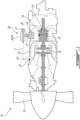
- FIG. 1 illustrates an exemplary gas turbine engine 10 (referred hereinafter as "engine 10"), which may be of a type preferably provided for use in subsonic flight of an aircraft.
- Engine 10 may comprise, in serial flow communication, propeller 12 through which ambient air is propelled, compressor 14 for pressurizing the air, combustor 16 in which the compressed air is mixed with fuel and ignited for generating an annular stream of hot combustion gases, and turbine section 18 including one or more turbines for extracting energy from the combustion gases.
- Compressor 14 of engine 10 may be a multi-stage compressor, and thus may comprise a plurality of axial and/or centrifugal compressor stages.
- Compressor 14, combustor 16 and turbine section 18 may be operatively disposed along gas path 19 of engine 10.
- engine 10 may be a reverse-flow turboprop gas turbine engine.
- FIG. 1 illustrates a turboprop engine, it is understood that the systems and methods described herein may be incorporated into other types of engines including engines of the turbofan and turboshaft type. It is also understood that the systems and methods described herein may be incorporated into aircraft and ground-based gas turbine engine applications.
- Engine 10 may include a system 20 for feeding pressurized air that is used as "muscle air” to control a function of a compressor bleed valve 22 (referred hereinafter as “bleed valve 22") of engine 10.
- Bleed valve 22 may be pneumatically-operated and may be opened to release air from compressor 14 to ambient environment 32. Bleed valve 22 may be opened to relieve pressure in a portion of gas path 19 at a stage of compressor 14.
- Bleed valve 22 may be a poppet valve having a hole, usually round or oval and a tapered plug, usually a disk shape on the end of a shaft. The shaft may guide the plug portion by sliding through a valve guide.
- a pressure differential may be used to seal the valve and, under certain operating conditions, open the valve.
- bleed valve 22 may be similar to the type of air bleed valve disclosed in US patent no. 8,572,985 B2 (titled: AIR FILTRATION SYSTEM FOR GAS TURBINE ENGINE PNEUMATIC SYSTEM) .
- System 20 may receive pressurized air from gas generator casing 23 of engine 10 and may distribute the pressurized air between bleed valve 22 and ambient environment 32 (e.g. atmosphere) as explained below.
- bleed valve 22 may be controlled by forces acting on opposite sides of bleed valve 22 which may relate to the respective air pressures P1, P2 at different locations along gas path 19.
- a spring may be provided to bias bleed valve 22 toward the open or closed position.
- pressure P1 may be taken in gas path 19 at an intermediate stage of compressor 14, and P2 may be taken in gas path 19 downstream of the location of P1.
- pressure P2 may be taken downstream of compressor 14 and upstream of combustor 16 so that pressure P2 may be higher than pressure P1.
- Pressure P2, or another pressure indicative thereof may be acquired via bleed air taken from gas path 19 at the desired location along gas path 19.
- the system 20 comprises an orifice pack 24, 24' configured for delivering "cleaned/decontaminated" bleed air to the bleed valve 22.
- pressure P2 may be taken at a location along gas path 19 providing the highest pressure within engine 10. Changes in the P1/P2 pressure relationship may cause bleed valve 22 to move between the open and closed positions.
- bleed valve 22 may be controlled by P1/P2 to maintain the operability of engine 10. In some situations, bleed valve 22 may, for example, prevent compressor stall at relatively low operating speeds of engine 10.
- FIG. 2 illustrates an exemplary embodiment of the orifice pack 24.
- the orifice pack 24 may be provided in the form of a fitting including a vent for discharging contaminants/particles carried by the pressurized air into the ambient environment 32.
- the orifice pack 24 is a conduit including an inlet 26 for receiving the pressurized (e.g., bleed) air F, a first outlet (e.g. a contaminated air outlet) 28 for releasing a first portion F1 of pressurized air F from conduit, and a second outlet (e.g. a clean air outlet) 30 for releasing a second portion F2 of pressurized air from the conduit.
- the conduit is configured so that a main portion of the pressurized air F is discharged through the first outlet 28 (F1 > F2).
- the first portion F1 is vented into the atmosphere 32 and the second portion F2 is directed to the pneumatically-actuated bleed valve 22.
- the inlet 26 and the first outlet 28 are axially aligned along a central axis of the conduit and the second outlet 30 is disposed axially therebetween and oriented along a direction intersecting the central axis.
- the inlet 26 and the first and second outlets 28, 30 may be sized to provide a desired flow rate and pressure drop across each of the inlet orifice and the outlet orifices. Such sizing may be based on specific operating parameters of engine 10 and the desired operating behaviour of bleed valve 22. As will be seen hereinafter, the inlet 26 and/or the outlets 28, 30 may include replaceable inserts to facilitate the use of orifice packs of similar configurations on different engines.
- the orifice pack 24 is provided in the form of a "tee" having a body 31 including a primary branch defining a diffusion chamber 34 between inlet 26 and the first outlet 28 and a secondary branch branching off at right angles from the primary branch at an axial location of the body 31 generally corresponding to a downstream end of the diffusion chamber 34.
- the secondary branch defines an outlet passage 30' extending through the wall of the diffusion chamber 34 in the primary branch. The secondary branch fluidly connects the diffusion chamber 34 to the second outlet 30, which is, in turn, connected in fluid communication to a control port of the bleed valve 22.
- the diffusion chamber 34 is configured for reducing the velocity and increasing the static pressure of the air passing through the system 20.
- the diffusion chamber 34 may have a cylindrical configuration, including a constant circular cross-sectional area.
- inlet 26 may include an inlet orifice defining a constriction (i.e., narrowing or reduced cross-sectional area of the available flow passage) relative to the diffusion chamber 34.
- the inlet 26 may include an orifice insert 26a adapted to be removably installed in a central inlet bore 26b of body 31.
- the orifice insert 26a may be threadably engaged with an internally threaded portion of the inlet bore 26b.
- the first outlet 28 is provided in the form of a vent detachably mounted to an end of the body 31 axially opposite to inlet 26.
- the vent is a two-piece body including a tapered extension piece 28a and an outlet orifice piece 28b.
- the tapered extension piece 28a improves the orifice pack's ability to eject contamination to provide cleaner air to the bleed valve 22 when fed high pressure air from the gas generator section 23.
- the tapered extension piece 28a defines a tapering passage 28c.
- the outlet orifice piece 28b defines a first outlet passage 28d.
- the tapering passage 28c and the first outlet passage 28d are axially aligned in serial flow communication when the two pieces of the vent are assembled to one another.
- the diffusion chamber 34 and the tapering passage 28c are aligned longitudinally and sequentially along the central axis of the primary branch of the orifice pack 24 when the extension piece 28a is mounted to the body 31.
- the tapering passage 28c converges towards the central axis in an axial direction away from the diffusion chamber 34 (i.e.
- passage 28c tapers in a downstream direction relative to a flow of air through the orifice pack 24) for venting the first portion F1 of the pressurized air F from the diffusion chamber 34.
- the tapering passage 28c helps the contaminants travel to the first outlet passage 28d without bouncing back, thereby improving the orifice pack's ability to eject contaminants carried in the air through the outlet passage 28d of the vent. This reduces the chances of contaminants travelling through the second outlet 30 and into the bleed valve 22.
- the extension piece 28a also moves the outlet orifice of the vent further downstream from the secondary outlet 30 (i.e. the clean air outlet), which may also improve particle separation.
- the diffusion chamber 34 has a diameter (B) and the tapering passage 28c has a length (A) along the central axis.
- a useful range of taper sizes has been determined to be: 1 ⁇ A/B ⁇ 4. However, it is understood that other ranges may be suitable depending on the intended application.
- the tapering passage 28c has a cross-sectional area at an inlet end that is at least equal to that of the diffusion chamber so as to avoid the presence of a flow constriction at the interface D between the diffusion chamber 34 and the downstream tapering passage 28c.
- the relative sizing of the cross-sectional area of the diffusion chamber 34 and the tapering passage 34 is selected to eliminate a protrusion into the gas path that could interfere with the contamination particles travelling towards the outlet passage 28d.
- the taper extension piece 28a is threadably mounted to the body 31.
- the body 31 has a connecting end axially opposite to the inlet 26, the connecting end defining and internally threaded bore 36 around the central axis of the primary branch of the body 31 at the outlet end of the diffusion chamber 34.
- the internally threaded bore 36 has a diameter greater than that of the diffusion chamber 34 to accommodate the extension piece 28a.
- the taper extension piece 28a has a male end 28a' with external threads for threaded engagement with the internally threaded bore 36 of the body 31, thereby allowing the extension piece 28a to be detachably mounted in series with the diffusion chamber 34.
- the internally threaded bore 36 and the male end 28a' of the extension piece 28a are sized so that the male end 28a' of the extension piece 28a does not protrude radially inwardly relative to the diffusion chamber 34.
- the outlet orifice piece 28b has an externally threaded end 28b' threadably engageable with complementary internal threads of a threaded bore 28a" defined at an end of the extension piece 28a opposite to its male end 28a'.
- the interface C between the downstream end of the extension piece 28a and the outlet orifice piece 28b is sized to minimize steps and gaps that could interfere with the flow of contamination particles.
- a minimal step can, however, be intentionally provided between the tapered extension piece 28a and outlet orifice piece 28b to help the entire orifice pack assembly continue to produce the necessary pressure for the bleed valve 22.
- the first outlet passage 28d has a cross-sectional area which is slightly smaller than the cross-sectional area at an outlet end of the tapering passage 28c, thereby providing for a flow constriction at interface C between the tapering passage 28c and the first outlet passage 28d.
- Fig. 3 illustrates another embodiment which essentially differs from the embodiment shown in Fig. 2 in that the vent has a monolithic body.
- the taper extension piece incorporate the secondary orifice feature, thereby reducing the number of parts in the assembly compared to the arrangement described above with reference to Fig. 2 .
- the cross-sectional area of the first outlet passage 28d is equal to the cross-sectional area at the outlet end of the tapering passage 28c.
- the orifice pack 24, 24' channels the high-pressure air through the inlet 26 into the diffusion chamber 34 from which a first portion F1 of the air vents to atmosphere 32 through the tapering passage 28c and the first outlet passage 28d.
- a second portion F2 of the air is tapped from the downstream end of the diffusion chamber 34 just upstream of the tapering passage 28c and fed to the bleed valve 22 via the second outlet 30.
- Any contamination taken from the gas generator case 23 will pass through the orifice pack inlet 26 and the major part will vent to atmosphere 32 through the first outlet 28.
- the tapering passage 28c extending axially in continuity from the diffusion chamber 34 will help the contamination particles carried by the air to flow toward the first outlet passage 28b, thereby reducing the chances of contaminants travelling to the bleed valve 22 via the second outlet 30.
Landscapes
- Engineering & Computer Science (AREA)
- Mechanical Engineering (AREA)
- General Engineering & Computer Science (AREA)
- Chemical & Material Sciences (AREA)
- Combustion & Propulsion (AREA)
- Life Sciences & Earth Sciences (AREA)
- Sustainable Development (AREA)
- Physics & Mathematics (AREA)
- Fluid Mechanics (AREA)
- Lift Valve (AREA)
- Jet Pumps And Other Pumps (AREA)
Claims (14)
- Blendenpaket (24; 24') zum Zuführen von komprimierter Luft an ein Kompressor-Entlüftungsventil (22), wobei das Blendenpaket (24; 24') Folgendes umfasst:einen Körper (31), der eine Diffusionskammer (34) definiert, die sich entlang einer Mittelachse erstreckt, wobei die Diffusionskammer (34) einen Einlass (26) aufweist, der mit einer Quelle von komprimierter Luft fluidverbindbar ist;einen Luftdurchlass (28), der entfernbar an dem Körper (31) montiert ist, wobei der Luftdurchlass (28) einen sich verjüngenden Kanal (28c) aufweist, wobei die Diffusionskammer (34) und der sich verjüngende Kanal (28c) in Längsrichtung und nacheinander entlang der Mittelachse ausgerichtet sind, wenn der Luftdurchlass (28) am Körper (31) montiert ist, wobei der sich verjüngende Kanal (28c) in axialer Richtung weg von der Diffusionskammer (34) zu einem ersten Auslasskanal (28d) hin konvergiert, um einen ersten Teil (F1) der komprimierten Luft aus der Diffusionskammer (34) abzulassen; undeinen zweiten Auslasskanal (30'), der von der Diffusionskammer (34) an einer axialen Stelle zwischen dem Einlass (26) und dem sich verjüngenden Kanal (28c) abzweigt, wobei der zweite Auslasskanal (30') mit dem Kompressor-Entlüftungsventil (22) fluidverbindbar ist, um einen zweiten Teil (F2) der komprimierten Luft von der Diffusionskammer (34) zu dem Kompressor-Entlüftungsventil (22) zu leiten;dadurch gekennzeichnet, dass der sich verjüngende Kanal (28c) an seinem Einlassende eine Querschnittsfläche aufweist, die mindestens gleich der der Diffusionskammer (34) ist, um so das Vorhandensein einer Strömungsverengung an einer Schnittstelle (D) zwischen der Diffusionskammer (34) und dem sich verjüngenden Kanal (28c) zu vermeiden.
- Blendenpaket (24; 24') nach Anspruch 1, wobei die Diffusionskammer (34) einen Durchmesser (B) aufweist, wobei der sich verjüngende Kanal (28c) eine Länge (A) entlang der Mittelachse aufweist und wobei 1 ≤ A/B ≤ 4.
- Blendenpaket (24; 24') nach Anspruch 1 oder 2, wobei der Luftdurchlass (28) ein Gewindeende (28a') aufweist, das mit dem Körper (31) in Gewindeeingriff steht.
- Blendenpaket (24) nach Anspruch 3, wobei der Körper (31) ein Verbindungsende axial gegenüber dem Einlass (26) der Diffusionskammer (34) aufweist, wobei das Verbindungsende eine Innengewindebohrung (36) um die Mittelachse definiert, wobei die Innengewindebohrung (36) einen größeren Durchmesser als die Diffusionskammer (34) aufweist, und wobei das Gewindeende (28a') des Luftdurchlasses ein Außengewinde zum Gewindeeingriff mit der Innengewindebohrung (36) des Körpers (31) aufweist.
- Blendenpaket (24; 24') nach Anspruch 4, wobei die Innengewindebohrung (36) und das Gewindeende (28a') des Luftdurchlasses (28) so bemessen sind, dass das Gewindeende (28a') des Luftdurchlasses (28) nicht radial nach innen relativ zu der Diffusionskammer (34) vorsteht.
- Blendenpaket (24; 24') nach einem der Ansprüche 1 bis 5, wobei der erste Auslasskanal (28d) eine Querschnittsfläche aufweist, die kleiner ist als eine Querschnittsfläche an einem Auslassende des sich verjüngenden Kanals (28c), um so eine Strömungsverengung an einer Schnittstelle zwischen dem sich verjüngenden Kanal (28c) und dem ersten Auslasskanal (28d) zu definieren.
- Blendenpaket (24) nach einem der Ansprüche 1 bis 6, wobei der Luftdurchlass (28) einen zweistückigen Körper aufweist, der ein erstes und ein zweites abnehmbares Stück (28a, 28b) beinhaltet, wobei der sich verjüngende Kanal (28c) und der erste Auslasskanal (28d) jeweils in dem ersten und dem zweiten abnehmbaren Stück (28a, 28b) definiert sind.
- Blendenpaket (24) nach Anspruch 7, wobei das zweite abnehmbare Stück (28b) ein Außengewinde zum Gewindeeingriff mit einem entsprechenden Innengewinde aufweist, das an dem ersten abnehmbaren Stück (28a) bereitgestellt ist.
- Blendenpaket (24') nach einem der Ansprüche 1 bis 6, wobei der Luftdurchlass (28) einen monolithischen Körper aufweist, wobei der sich verjüngende Kanal (28c) und der erste Auslasskanal (28d) sich in Längsrichtung durchgehend axial durch den monolithischen Körper erstrecken.
- Blendenpaket (24; 24') nach einem der Ansprüche 1 bis 9, wobei der zweite Auslasskanal (30') axial benachbart zu dem sich verjüngenden Kanal (28c) an einem stromabwärtigen Ende der Diffusionskammer (34) positioniert ist.
- Blendenpaket (24; 24') nach Anspruch 10, wobei der zweite Auslasskanal (30') in einer Abzweigung definiert ist, die sich integral von dem Körper (31) erstreckt.
- Blendenpaket (24) nach einem der Ansprüche 1 bis 11, wobei der Einlass (26) einen primären Blendeneinsatz (26a) umfasst, der entfernbar in einer in dem Körper (31) definierten Aufnahmebohrung (26b) montiert ist, wobei der primäre Blendeneinsatz (26a) eine erste Verengung definiert.
- Kompressor-Entlüftungsventilanordnung zum selektiven Abblasen von Luft aus einem Kompressor (14), wobei die Kompressor-Entlüftungsventilanordnung Folgendes umfasst:ein pneumatisch betätigbares Kompressor-Entlüftungsventil (22), das einen Steueranschluss aufweist; unddas Blendenpaket (24; 24') nach einem der Ansprüche 1 bis 12, wobei das Blendenpaket (24; 24') mit dem Steueranschluss des pneumatisch betätigbaren Kompressor-Entlüftungsventils (22) fluidverbunden ist,wobei der zweite Auslasskanal (30') mit dem Steueranschluss des pneumatisch betätigbaren Kompressor-Entlüftungsventils (22) fluidverbunden ist.
- Gasturbinentriebwerk (10), umfassend:einen Kompressor (14) zum Komprimieren von Luft;eine Brennkammer (16), in der die komprimierte Luft mit Kraftstoff vermischt und gezündet wird, zum Erzeugen eines Stroms von Verbrennungsgas;eine Turbine (18) zum Extrahieren von Energie aus dem Verbrennungsgas, wobei der Kompressor (14), die Brennkammer (16) und die Turbine (18) betriebsmäßig entlang eines Gaswegs (19) des Gasturbinentriebwerks (10) angeordnet sind;eine pneumatisch betätigbare Kompressor-Entlüftungsventilanordnung nach Anspruch 13 zum Abblasen von komprimierter Luft aus dem Kompressor (14).
Applications Claiming Priority (1)
| Application Number | Priority Date | Filing Date | Title |
|---|---|---|---|
| US17/389,450 US11852073B2 (en) | 2021-07-30 | 2021-07-30 | Orifice pack for compressor bleed valve |
Publications (2)
| Publication Number | Publication Date |
|---|---|
| EP4124739A1 EP4124739A1 (de) | 2023-02-01 |
| EP4124739B1 true EP4124739B1 (de) | 2025-06-11 |
Family
ID=83049897
Family Applications (1)
| Application Number | Title | Priority Date | Filing Date |
|---|---|---|---|
| EP22188162.6A Active EP4124739B1 (de) | 2021-07-30 | 2022-08-01 | Blendenpaket für kompressor-entlüftungsventil |
Country Status (3)
| Country | Link |
|---|---|
| US (1) | US11852073B2 (de) |
| EP (1) | EP4124739B1 (de) |
| CA (1) | CA3168429A1 (de) |
Families Citing this family (3)
| Publication number | Priority date | Publication date | Assignee | Title |
|---|---|---|---|---|
| US11821363B1 (en) * | 2022-05-06 | 2023-11-21 | Pratt & Whitney Canada Corp. | Apparatus for removing particulate matter from bleed gas and gas turbine engine including same |
| US20250172095A1 (en) * | 2023-11-29 | 2025-05-29 | General Electric Company | Turbomachine with axial thrust management |
| US20250257689A1 (en) * | 2024-02-08 | 2025-08-14 | Pratt & Whitney Canada Corp. | Bleed-off assembly intake device for an aircraft propulsion system |
Family Cites Families (33)
| Publication number | Priority date | Publication date | Assignee | Title |
|---|---|---|---|---|
| USRE16842E (en) * | 1928-01-03 | Jvrancis h | ||
| US408787A (en) * | 1889-08-13 | Joseph s | ||
| US2047568A (en) * | 1935-07-08 | 1936-07-14 | Int Precipitation Co | Method and apparatus for separating suspended particles from gases |
| US4469497A (en) * | 1982-02-04 | 1984-09-04 | Linhardt & Associates, Inc. | Axisymmetrical separator for separating particulate matter from a fluid carrying medium |
| US4592765A (en) * | 1985-01-15 | 1986-06-03 | Pratt & Whitney Canada Inc. | Inertial separator |
| US5549721A (en) * | 1994-12-02 | 1996-08-27 | Shchipachev; Viktor | Cell for gas cleaning |
| RU2109971C1 (ru) | 1995-07-06 | 1998-04-27 | Открытое акционерное общество "Рыбинские моторы" | Устройство для управления воздушным стартером |
| US5799593A (en) * | 1996-06-17 | 1998-09-01 | Mcdermott Technology, Inc. | Drainable discharge pan for impact type particle separator |
| JP2000104547A (ja) | 1998-09-28 | 2000-04-11 | Nissan Diesel Motor Co Ltd | 内燃機関の冷却装置 |
| US6238451B1 (en) * | 1999-01-08 | 2001-05-29 | Fantom Technologies Inc. | Vacuum cleaner |
| PT102392A (pt) * | 1999-12-13 | 2000-11-30 | Romualdo Luis Ribera Salcedo | Ciclones de recirculacao para despoeiramento e lavagem de gases |
| US6692553B2 (en) * | 2001-10-10 | 2004-02-17 | Environmental Monitoring Systems, Inc. | Particle collection apparatus and method |
| FR2889565B1 (fr) | 2005-08-03 | 2012-05-18 | Snecma | Compresseur a prelevement d'air centripete |
| US7841186B2 (en) | 2007-01-31 | 2010-11-30 | Power Systems Mfg., Llc | Inlet bleed heat and power augmentation for a gas turbine engine |
| US10286407B2 (en) | 2007-11-29 | 2019-05-14 | General Electric Company | Inertial separator |
| US7837753B2 (en) * | 2007-11-30 | 2010-11-23 | Honeywell International Inc. | Systems for filtering particles from an airflow |
| US8572985B2 (en) * | 2009-06-26 | 2013-11-05 | Pratt & Whitney Canada Corp. | Air filtration system for gas turbine engine pneumatic system |
| US8695352B2 (en) | 2012-07-12 | 2014-04-15 | Solar Turbines Inc. | Baffle assembly for bleed air system of gas turbine engine |
| JP6021540B2 (ja) * | 2012-09-12 | 2016-11-09 | 三菱日立パワーシステムズ株式会社 | 捕集装置及びこれを備えるガスタービンプラント |
| US20140298788A1 (en) | 2013-04-08 | 2014-10-09 | United Technologies Corporation | Gas turbine engine including pneumatic actuator system |
| US20140346379A1 (en) | 2013-05-23 | 2014-11-27 | Hamilton Sundstrand Corporation | Backflow prevention valve |
| US20150096641A1 (en) * | 2013-10-04 | 2015-04-09 | Pratt & Whitney Canada Corp. | Flow regulating apparatus |
| FR3027973B1 (fr) | 2014-10-29 | 2020-02-14 | Safran Aircraft Engines | Carter de turbomachine, comprenant un dispositif de guidage de l'air en rotation dans le carter |
| US10245540B2 (en) | 2017-01-09 | 2019-04-02 | Pratt & Whitney Canada Corp. | Inertial particle separator for engine inlet |
| US10512876B2 (en) | 2017-02-13 | 2019-12-24 | Hamilton Sundstrand Corporation | Air filter for bleed valve assembly |
| EP4194676A1 (de) | 2017-05-25 | 2023-06-14 | Ge Avio S.r.l. | Steuerung eines verdichters eines turbinenmotors |
| US11078841B2 (en) | 2018-04-09 | 2021-08-03 | The Boeing Company | Bleed air systems for use with aircraft and related methods |
| US10781710B2 (en) | 2018-07-17 | 2020-09-22 | Raytheon Technologies Corporation | Sealing configuration to reduce air leakage |
| US10626802B2 (en) | 2018-09-21 | 2020-04-21 | United Technologies Corporation | Ducted gas turbine engine stability bleed valve with passive and active shutoff |
| US11346249B2 (en) | 2019-03-05 | 2022-05-31 | Pratt & Whitney Canada Corp. | Gas turbine engine with feed pipe for bearing housing |
| US11008889B2 (en) | 2019-03-18 | 2021-05-18 | General Electric Company | Turbine engine hanger |
| US10824172B1 (en) | 2019-06-20 | 2020-11-03 | Hamilton Sunstrand Corporation | Pneumatic controllers, pneumatically controlled inline valves, and methods of actuating inline valves |
| US11698005B2 (en) | 2020-02-07 | 2023-07-11 | Raytheon Technologies Corporation | Flow diverter for mid-turbine frame cooling air delivery |
-
2021
- 2021-07-30 US US17/389,450 patent/US11852073B2/en active Active
-
2022
- 2022-07-21 CA CA3168429A patent/CA3168429A1/en active Pending
- 2022-08-01 EP EP22188162.6A patent/EP4124739B1/de active Active
Also Published As
| Publication number | Publication date |
|---|---|
| US11852073B2 (en) | 2023-12-26 |
| EP4124739A1 (de) | 2023-02-01 |
| CA3168429A1 (en) | 2023-01-30 |
| US20230029960A1 (en) | 2023-02-02 |
Similar Documents
| Publication | Publication Date | Title |
|---|---|---|
| EP4124739B1 (de) | Blendenpaket für kompressor-entlüftungsventil | |
| US6701715B2 (en) | Variable geometry ejector for a bleed air system using integral ejector exit pressure feedback | |
| US9988936B2 (en) | Shroud assembly for a gas turbine engine | |
| EP3108129B1 (de) | Zwischengehäusestruktur für einen gasturbinenmotorverdichter mit einem integrierten verteiler für klimaregelungssystem und verfahren zur bereitstellung sauberer zapfluft für das klimaregelungssystem | |
| US8657567B2 (en) | Nacelle compartment plenum for bleed air flow delivery system | |
| US7837753B2 (en) | Systems for filtering particles from an airflow | |
| EP3260687A1 (de) | Einlasspartikelabscheidersystem mit vorreinigungsströmungskanal | |
| EP3561265B1 (de) | Gasturbinenmotor mit trägheitspartikelabscheider | |
| EP4155522A1 (de) | Einlassvorrichtung für gasturbinenmotor | |
| US10428664B2 (en) | Nozzle for a gas turbine engine | |
| EP3133265B1 (de) | Vorrichtung und verfahren eines luftpartikelabscheiders in einem gasturbinenmotor | |
| EP4108896B1 (de) | Luftfiltersystem und verfahren für das entlüftungsventil eines verdichters | |
| EP3604140B1 (de) | Lufteinlasssystem für hilfsaggregate | |
| EP3966443B1 (de) | Umkehrbare ablassvorrichtung | |
| EP1845294A2 (de) | Geführtes pneumatisches Schaltventil der zweiten Stufe | |
| EP2812548B1 (de) | Gasturbinenmotor | |
| US20200102886A1 (en) | Customer bleed air pressure loss reduction | |
| EP2904243A1 (de) | Aerodynamische interkompressorauslässe |
Legal Events
| Date | Code | Title | Description |
|---|---|---|---|
| PUAI | Public reference made under article 153(3) epc to a published international application that has entered the european phase |
Free format text: ORIGINAL CODE: 0009012 |
|
| STAA | Information on the status of an ep patent application or granted ep patent |
Free format text: STATUS: THE APPLICATION HAS BEEN PUBLISHED |
|
| AK | Designated contracting states |
Kind code of ref document: A1 Designated state(s): AL AT BE BG CH CY CZ DE DK EE ES FI FR GB GR HR HU IE IS IT LI LT LU LV MC MK MT NL NO PL PT RO RS SE SI SK SM TR |
|
| STAA | Information on the status of an ep patent application or granted ep patent |
Free format text: STATUS: REQUEST FOR EXAMINATION WAS MADE |
|
| 17P | Request for examination filed |
Effective date: 20230801 |
|
| RBV | Designated contracting states (corrected) |
Designated state(s): AL AT BE BG CH CY CZ DE DK EE ES FI FR GB GR HR HU IE IS IT LI LT LU LV MC MK MT NL NO PL PT RO RS SE SI SK SM TR |
|
| GRAP | Despatch of communication of intention to grant a patent |
Free format text: ORIGINAL CODE: EPIDOSNIGR1 |
|
| STAA | Information on the status of an ep patent application or granted ep patent |
Free format text: STATUS: GRANT OF PATENT IS INTENDED |
|
| INTG | Intention to grant announced |
Effective date: 20250103 |
|
| GRAS | Grant fee paid |
Free format text: ORIGINAL CODE: EPIDOSNIGR3 |
|
| GRAA | (expected) grant |
Free format text: ORIGINAL CODE: 0009210 |
|
| STAA | Information on the status of an ep patent application or granted ep patent |
Free format text: STATUS: THE PATENT HAS BEEN GRANTED |
|
| AK | Designated contracting states |
Kind code of ref document: B1 Designated state(s): AL AT BE BG CH CY CZ DE DK EE ES FI FR GB GR HR HU IE IS IT LI LT LU LV MC MK MT NL NO PL PT RO RS SE SI SK SM TR |
|
| REG | Reference to a national code |
Ref country code: GB Ref legal event code: FG4D |
|
| REG | Reference to a national code |
Ref country code: CH Ref legal event code: EP |
|
| REG | Reference to a national code |
Ref country code: DE Ref legal event code: R096 Ref document number: 602022015745 Country of ref document: DE |
|
| REG | Reference to a national code |
Ref country code: IE Ref legal event code: FG4D |
|
| PG25 | Lapsed in a contracting state [announced via postgrant information from national office to epo] |
Ref country code: FI Free format text: LAPSE BECAUSE OF FAILURE TO SUBMIT A TRANSLATION OF THE DESCRIPTION OR TO PAY THE FEE WITHIN THE PRESCRIBED TIME-LIMIT Effective date: 20250611 Ref country code: ES Free format text: LAPSE BECAUSE OF FAILURE TO SUBMIT A TRANSLATION OF THE DESCRIPTION OR TO PAY THE FEE WITHIN THE PRESCRIBED TIME-LIMIT Effective date: 20250611 |
|
| PGFP | Annual fee paid to national office [announced via postgrant information from national office to epo] |
Ref country code: DE Payment date: 20250724 Year of fee payment: 4 |
|
| REG | Reference to a national code |
Ref country code: LT Ref legal event code: MG9D |
|
| PG25 | Lapsed in a contracting state [announced via postgrant information from national office to epo] |
Ref country code: GR Free format text: LAPSE BECAUSE OF FAILURE TO SUBMIT A TRANSLATION OF THE DESCRIPTION OR TO PAY THE FEE WITHIN THE PRESCRIBED TIME-LIMIT Effective date: 20250912 Ref country code: NO Free format text: LAPSE BECAUSE OF FAILURE TO SUBMIT A TRANSLATION OF THE DESCRIPTION OR TO PAY THE FEE WITHIN THE PRESCRIBED TIME-LIMIT Effective date: 20250911 |
|
| REG | Reference to a national code |
Ref country code: NL Ref legal event code: MP Effective date: 20250611 |
|
| PG25 | Lapsed in a contracting state [announced via postgrant information from national office to epo] |
Ref country code: BG Free format text: LAPSE BECAUSE OF FAILURE TO SUBMIT A TRANSLATION OF THE DESCRIPTION OR TO PAY THE FEE WITHIN THE PRESCRIBED TIME-LIMIT Effective date: 20250611 |
|
| PG25 | Lapsed in a contracting state [announced via postgrant information from national office to epo] |
Ref country code: HR Free format text: LAPSE BECAUSE OF FAILURE TO SUBMIT A TRANSLATION OF THE DESCRIPTION OR TO PAY THE FEE WITHIN THE PRESCRIBED TIME-LIMIT Effective date: 20250611 |
|
| PGFP | Annual fee paid to national office [announced via postgrant information from national office to epo] |
Ref country code: AT Payment date: 20251020 Year of fee payment: 4 Ref country code: FR Payment date: 20250725 Year of fee payment: 4 |
|
| PG25 | Lapsed in a contracting state [announced via postgrant information from national office to epo] |
Ref country code: RS Free format text: LAPSE BECAUSE OF FAILURE TO SUBMIT A TRANSLATION OF THE DESCRIPTION OR TO PAY THE FEE WITHIN THE PRESCRIBED TIME-LIMIT Effective date: 20250911 |
|
| PG25 | Lapsed in a contracting state [announced via postgrant information from national office to epo] |
Ref country code: LV Free format text: LAPSE BECAUSE OF FAILURE TO SUBMIT A TRANSLATION OF THE DESCRIPTION OR TO PAY THE FEE WITHIN THE PRESCRIBED TIME-LIMIT Effective date: 20250611 |
|
| PG25 | Lapsed in a contracting state [announced via postgrant information from national office to epo] |
Ref country code: NL Free format text: LAPSE BECAUSE OF FAILURE TO SUBMIT A TRANSLATION OF THE DESCRIPTION OR TO PAY THE FEE WITHIN THE PRESCRIBED TIME-LIMIT Effective date: 20250611 |
|
| PG25 | Lapsed in a contracting state [announced via postgrant information from national office to epo] |
Ref country code: PT Free format text: LAPSE BECAUSE OF FAILURE TO SUBMIT A TRANSLATION OF THE DESCRIPTION OR TO PAY THE FEE WITHIN THE PRESCRIBED TIME-LIMIT Effective date: 20251013 |
|
| REG | Reference to a national code |
Ref country code: AT Ref legal event code: MK05 Ref document number: 1802433 Country of ref document: AT Kind code of ref document: T Effective date: 20250611 |
|
| PG25 | Lapsed in a contracting state [announced via postgrant information from national office to epo] |
Ref country code: IS Free format text: LAPSE BECAUSE OF FAILURE TO SUBMIT A TRANSLATION OF THE DESCRIPTION OR TO PAY THE FEE WITHIN THE PRESCRIBED TIME-LIMIT Effective date: 20251011 |
|
| PG25 | Lapsed in a contracting state [announced via postgrant information from national office to epo] |
Ref country code: AT Free format text: LAPSE BECAUSE OF FAILURE TO SUBMIT A TRANSLATION OF THE DESCRIPTION OR TO PAY THE FEE WITHIN THE PRESCRIBED TIME-LIMIT Effective date: 20250611 Ref country code: SM Free format text: LAPSE BECAUSE OF FAILURE TO SUBMIT A TRANSLATION OF THE DESCRIPTION OR TO PAY THE FEE WITHIN THE PRESCRIBED TIME-LIMIT Effective date: 20250611 |
|
| PG25 | Lapsed in a contracting state [announced via postgrant information from national office to epo] |
Ref country code: CZ Free format text: LAPSE BECAUSE OF FAILURE TO SUBMIT A TRANSLATION OF THE DESCRIPTION OR TO PAY THE FEE WITHIN THE PRESCRIBED TIME-LIMIT Effective date: 20250611 |
|
| PG25 | Lapsed in a contracting state [announced via postgrant information from national office to epo] |
Ref country code: PL Free format text: LAPSE BECAUSE OF FAILURE TO SUBMIT A TRANSLATION OF THE DESCRIPTION OR TO PAY THE FEE WITHIN THE PRESCRIBED TIME-LIMIT Effective date: 20250611 |
|
| PG25 | Lapsed in a contracting state [announced via postgrant information from national office to epo] |
Ref country code: EE Free format text: LAPSE BECAUSE OF FAILURE TO SUBMIT A TRANSLATION OF THE DESCRIPTION OR TO PAY THE FEE WITHIN THE PRESCRIBED TIME-LIMIT Effective date: 20250611 |
|
| PG25 | Lapsed in a contracting state [announced via postgrant information from national office to epo] |
Ref country code: SK Free format text: LAPSE BECAUSE OF FAILURE TO SUBMIT A TRANSLATION OF THE DESCRIPTION OR TO PAY THE FEE WITHIN THE PRESCRIBED TIME-LIMIT Effective date: 20250611 |
|
| PG25 | Lapsed in a contracting state [announced via postgrant information from national office to epo] |
Ref country code: RO Free format text: LAPSE BECAUSE OF FAILURE TO SUBMIT A TRANSLATION OF THE DESCRIPTION OR TO PAY THE FEE WITHIN THE PRESCRIBED TIME-LIMIT Effective date: 20250611 |
|
| REG | Reference to a national code |
Ref country code: DE Ref legal event code: R097 Ref document number: 602022015745 Country of ref document: DE |
|
| REG | Reference to a national code |
Ref country code: CH Ref legal event code: H13 Free format text: ST27 STATUS EVENT CODE: U-0-0-H10-H13 (AS PROVIDED BY THE NATIONAL OFFICE) Effective date: 20260324 |
|
| PG25 | Lapsed in a contracting state [announced via postgrant information from national office to epo] |
Ref country code: MC Free format text: LAPSE BECAUSE OF FAILURE TO SUBMIT A TRANSLATION OF THE DESCRIPTION OR TO PAY THE FEE WITHIN THE PRESCRIBED TIME-LIMIT Effective date: 20250611 |
|
| PG25 | Lapsed in a contracting state [announced via postgrant information from national office to epo] |
Ref country code: DK Free format text: LAPSE BECAUSE OF FAILURE TO SUBMIT A TRANSLATION OF THE DESCRIPTION OR TO PAY THE FEE WITHIN THE PRESCRIBED TIME-LIMIT Effective date: 20250611 |
|
| PG25 | Lapsed in a contracting state [announced via postgrant information from national office to epo] |
Ref country code: LU Free format text: LAPSE BECAUSE OF NON-PAYMENT OF DUE FEES Effective date: 20250801 Ref country code: IT Free format text: LAPSE BECAUSE OF FAILURE TO SUBMIT A TRANSLATION OF THE DESCRIPTION OR TO PAY THE FEE WITHIN THE PRESCRIBED TIME-LIMIT Effective date: 20250611 |
|
| PLBE | No opposition filed within time limit |
Free format text: ORIGINAL CODE: 0009261 |
|
| STAA | Information on the status of an ep patent application or granted ep patent |
Free format text: STATUS: NO OPPOSITION FILED WITHIN TIME LIMIT |
|
| PG25 | Lapsed in a contracting state [announced via postgrant information from national office to epo] |
Ref country code: CH Free format text: LAPSE BECAUSE OF NON-PAYMENT OF DUE FEES Effective date: 20250831 |
|
| REG | Reference to a national code |
Ref country code: CH Ref legal event code: L10 Free format text: ST27 STATUS EVENT CODE: U-0-0-L10-L00 (AS PROVIDED BY THE NATIONAL OFFICE) Effective date: 20260423 |