EP4124733A1 - Two-cycle engine - Google Patents
Two-cycle engine Download PDFInfo
- Publication number
- EP4124733A1 EP4124733A1 EP22187623.8A EP22187623A EP4124733A1 EP 4124733 A1 EP4124733 A1 EP 4124733A1 EP 22187623 A EP22187623 A EP 22187623A EP 4124733 A1 EP4124733 A1 EP 4124733A1
- Authority
- EP
- European Patent Office
- Prior art keywords
- cylinder
- scavenging
- passage
- communication passage
- port
- Prior art date
- Legal status (The legal status is an assumption and is not a legal conclusion. Google has not performed a legal analysis and makes no representation as to the accuracy of the status listed.)
- Granted
Links
- 230000002000 scavenging effect Effects 0.000 claims abstract description 179
- 238000002485 combustion reaction Methods 0.000 claims abstract description 54
- 239000007789 gas Substances 0.000 description 61
- 239000000203 mixture Substances 0.000 description 52
- 239000004215 Carbon black (E152) Substances 0.000 description 7
- 229930195733 hydrocarbon Natural products 0.000 description 7
- 150000002430 hydrocarbons Chemical class 0.000 description 7
- 238000000034 method Methods 0.000 description 7
- 230000008569 process Effects 0.000 description 7
- 239000000567 combustion gas Substances 0.000 description 5
- 238000000889 atomisation Methods 0.000 description 3
- 238000007906 compression Methods 0.000 description 3
- 239000000446 fuel Substances 0.000 description 3
- 230000004044 response Effects 0.000 description 3
- 230000007246 mechanism Effects 0.000 description 1
- 238000012986 modification Methods 0.000 description 1
- 230000004048 modification Effects 0.000 description 1
- 230000003584 silencer Effects 0.000 description 1
- 230000007480 spreading Effects 0.000 description 1
- 239000002699 waste material Substances 0.000 description 1
Images


Classifications
-
- F—MECHANICAL ENGINEERING; LIGHTING; HEATING; WEAPONS; BLASTING
- F02—COMBUSTION ENGINES; HOT-GAS OR COMBUSTION-PRODUCT ENGINE PLANTS
- F02B—INTERNAL-COMBUSTION PISTON ENGINES; COMBUSTION ENGINES IN GENERAL
- F02B25/00—Engines characterised by using fresh charge for scavenging cylinders
- F02B25/14—Engines characterised by using fresh charge for scavenging cylinders using reverse-flow scavenging, e.g. with both outlet and inlet ports arranged near bottom of piston stroke
- F02B25/16—Engines characterised by using fresh charge for scavenging cylinders using reverse-flow scavenging, e.g. with both outlet and inlet ports arranged near bottom of piston stroke the charge flowing upward essentially along cylinder wall opposite the inlet ports
-
- F—MECHANICAL ENGINEERING; LIGHTING; HEATING; WEAPONS; BLASTING
- F02—COMBUSTION ENGINES; HOT-GAS OR COMBUSTION-PRODUCT ENGINE PLANTS
- F02F—CYLINDERS, PISTONS OR CASINGS, FOR COMBUSTION ENGINES; ARRANGEMENTS OF SEALINGS IN COMBUSTION ENGINES
- F02F1/00—Cylinders; Cylinder heads
- F02F1/18—Other cylinders
- F02F1/22—Other cylinders characterised by having ports in cylinder wall for scavenging or charging
-
- F—MECHANICAL ENGINEERING; LIGHTING; HEATING; WEAPONS; BLASTING
- F02—COMBUSTION ENGINES; HOT-GAS OR COMBUSTION-PRODUCT ENGINE PLANTS
- F02B—INTERNAL-COMBUSTION PISTON ENGINES; COMBUSTION ENGINES IN GENERAL
- F02B25/00—Engines characterised by using fresh charge for scavenging cylinders
- F02B25/14—Engines characterised by using fresh charge for scavenging cylinders using reverse-flow scavenging, e.g. with both outlet and inlet ports arranged near bottom of piston stroke
-
- F—MECHANICAL ENGINEERING; LIGHTING; HEATING; WEAPONS; BLASTING
- F02—COMBUSTION ENGINES; HOT-GAS OR COMBUSTION-PRODUCT ENGINE PLANTS
- F02B—INTERNAL-COMBUSTION PISTON ENGINES; COMBUSTION ENGINES IN GENERAL
- F02B25/00—Engines characterised by using fresh charge for scavenging cylinders
- F02B25/20—Means for reducing the mixing of charge and combustion residues or for preventing escape of fresh charge through outlet ports not provided for in, or of interest apart from, subgroups F02B25/02 - F02B25/18
- F02B25/24—Inlet or outlet openings being timed asymmetrically relative to bottom dead-centre
-
- F—MECHANICAL ENGINEERING; LIGHTING; HEATING; WEAPONS; BLASTING
- F02—COMBUSTION ENGINES; HOT-GAS OR COMBUSTION-PRODUCT ENGINE PLANTS
- F02B—INTERNAL-COMBUSTION PISTON ENGINES; COMBUSTION ENGINES IN GENERAL
- F02B33/00—Engines characterised by provision of pumps for charging or scavenging
- F02B33/02—Engines with reciprocating-piston pumps; Engines with crankcase pumps
- F02B33/04—Engines with reciprocating-piston pumps; Engines with crankcase pumps with simple crankcase pumps, i.e. with the rear face of a non-stepped working piston acting as sole pumping member in co-operation with the crankcase
-
- F—MECHANICAL ENGINEERING; LIGHTING; HEATING; WEAPONS; BLASTING
- F02—COMBUSTION ENGINES; HOT-GAS OR COMBUSTION-PRODUCT ENGINE PLANTS
- F02F—CYLINDERS, PISTONS OR CASINGS, FOR COMBUSTION ENGINES; ARRANGEMENTS OF SEALINGS IN COMBUSTION ENGINES
- F02F7/00—Casings, e.g. crankcases or frames
- F02F7/0021—Construction
- F02F7/0036—Casings for two-stroke engines with scavenging conduits
-
- F—MECHANICAL ENGINEERING; LIGHTING; HEATING; WEAPONS; BLASTING
- F02—COMBUSTION ENGINES; HOT-GAS OR COMBUSTION-PRODUCT ENGINE PLANTS
- F02B—INTERNAL-COMBUSTION PISTON ENGINES; COMBUSTION ENGINES IN GENERAL
- F02B75/00—Other engines
- F02B75/02—Engines characterised by their cycles, e.g. six-stroke
- F02B2075/022—Engines characterised by their cycles, e.g. six-stroke having less than six strokes per cycle
- F02B2075/025—Engines characterised by their cycles, e.g. six-stroke having less than six strokes per cycle two
-
- Y—GENERAL TAGGING OF NEW TECHNOLOGICAL DEVELOPMENTS; GENERAL TAGGING OF CROSS-SECTIONAL TECHNOLOGIES SPANNING OVER SEVERAL SECTIONS OF THE IPC; TECHNICAL SUBJECTS COVERED BY FORMER USPC CROSS-REFERENCE ART COLLECTIONS [XRACs] AND DIGESTS
- Y02—TECHNOLOGIES OR APPLICATIONS FOR MITIGATION OR ADAPTATION AGAINST CLIMATE CHANGE
- Y02T—CLIMATE CHANGE MITIGATION TECHNOLOGIES RELATED TO TRANSPORTATION
- Y02T10/00—Road transport of goods or passengers
- Y02T10/10—Internal combustion engine [ICE] based vehicles
- Y02T10/12—Improving ICE efficiencies
Definitions
- the present invention relates to a two-cycle engine, i.e., a two-stroke internal combustion engine (hereinafter referred to as a "two-stroke engine"), used on a portable power working machine.
- a two-cycle engine i.e., a two-stroke internal combustion engine (hereinafter referred to as a "two-stroke engine")
- a cylinder block of a two-stroke engine used on a portable power working machine such as chainsaws, brush cutters, and blowers
- an intake passage leading to a crank chamber an exhaust passage leading to a combustion chamber of an upper portion of the cylinder, and a scavenging passage communicating between the crank chamber and the combustion chamber.
- an air-fuel mixture gas (hereinafter referred to as a "mixture gas”) flows into the crank chamber through the intake passage. Then, the mixture gas flows into the combustion chamber through the scavenging passage, and the mixture gas is combusted in the combustion chamber, and by an expansion power of the mixture gas when combusted in the combustion chamber, a piston is reciprocated in the cylinder (for example, see JP 2009-002311 A ).
- a scavenging port of the scavenging passage is opened to the upper portion of the cylinder, and the mixture gas in the crank chamber flows into the combustion chamber through the scavenging passage (scavenging process).
- the present invention has been developed to solve the above-described problem, and an object of the invention is to provide a two-stroke engine that enables the unburned gas contained in the exhaust gas to be reduced, and the scavenging efficiency and the combustion efficiency to be improved.
- the present invention provides a two-stroke engine comprising: a cylinder block formed with a cylinder and a crank chamber; and a piston slidably mounted in the cylinder.
- the cylinder block includes: an exhaust passage leading to a combustion chamber in the cylinder through an exhaust port opened to an inner circumferential surface of the cylinder; a scavenging port opened to the inner circumferential surface of the cylinder; a communication passage extending from the scavenging port in a radial direction of the cylinder; and a scavenging passage extending in an axial direction of the cylinder, communicating with the crank chamber, and having an opening portion formed in a bottom surface of the communication passage.
- a ceiling surface of the communication passage is inclined toward a cylinder head with increasing distance from a scavenging passage side thereof toward the scavenging port. Further, a bottom surface of the communication passage is inclined toward the crank chamber with increasing distance from a scavenging passage side thereof toward the scavenging port.
- the communication passage between the scavenging passage and the scavenging port is expanded in the axial direction of the cylinder with increasing distance from a scavenging passage side thereof toward the scavenging port.
- the mixture gas compressed in the scavenging passage is expanded to a large extent in the communication passage and jetted from the scavenging port into the combustion chamber, so that the mixture gas can be dispersed widely in the combustion chamber. This can improve the scavenging efficiency and the combustion efficiency.
- a scavenging flow (mixture gas) is expanded in the communication passage, atomization of the mixture gas can be promoted and the mixture gas can be guided into the combustion chamber while spreading in the axial direction of the cylinder.
- the two-stroke engine according to the present invention can improve power output and response, while significantly reducing the amount of hydrocarbon (HC) contained in the exhaust gas.
- an engine 1 is a two-stroke engine used for portable power working machines such as chainsaws, brush cutters, and blowers.
- the engine 1 includes a cylinder block 60 formed with a cylinder 61a and a crank chamber 62a, a piston 50 slidably mounted in the cylinder 61a, and a crank shaft 90 arranged in the crank chamber 62a.
- the engine 1 further includes an intake passage 70 leading to the crank chamber 62a, an exhaust passage 80 leading to a combustion chamber 40, and a first scavenging passage 10A and second scavenging passages 10B (see FIG. 5 ) that make the crank chamber 62a and the combustion chamber 40 communicate with each other.
- the first scavenging passage 10A and the second scavenging passage 10B are in communication with the combustion chamber 40, and the mixture gas flows into the combustion chamber 40 through the first scavenging passage 10A and the second scavenging passage 10B.
- the cylinder block 60 is divided into a cylinder head 63, an upper block 61 formed with the cylinder 61a and an upper portion of the crank chamber 62a, and a lower case 62 formed with a lower portion of the crank chamber 62a.
- the upper block 61 and the lower case 62 are assembled one above the other.
- crank journal 91 Formed on the crank shaft 90 are a crank journal 91 rotatably supported on the lower case 62 and a crank web 92 formed on the crank journal 91.
- Bearings 62d are fitted into inner circumferential surfaces of inserting holes 62c formed in sidewall portions 62b of the lower case 62.
- crank journal 91 is inserted into the bearings 62d, and the leading ends of the crank journal protrude outside from the lower case 62.
- crank web 92 is coupled with the piston 50 via a connecting rod 51, and the crank web 92 is configured to rotate around an axis of the crank journal 91 in response to the reciprocation of the piston 50.
- the intake passage 70 is formed on a side portion (a right side portion in FIG. 2 ) of the upper block 61, and one end thereof is opened to a lower portion of the cylinder 61a and the other end thereof is connected to a fuel supply passage (not shown).
- an opening portion 71 of the intake passage 70 that is closer to the cylinder 61a is blocked by a side surface of the piston 50 when the piston 50 is positioned at the bottom dead point, and is opened, as seen in FIG. 2 , to the lower portion of the cylinder 61a communicating with the crank chamber 62a when the piston 50 is positioned at the top dead point.
- the exhaust passage 80 is formed on a side portion (a left side portion in FIG. 2 ) of the upper block 61 at a position opposite to the intake passage 70.
- One end of the exhaust passage 80 is formed with an exhaust port 81 opened to an inner circumferential surface of the cylinder 61a, and the other end thereof is connected to a muffler or silencer (not shown).
- the exhaust port 81 is in communication with the combustion chamber 40 when the piston 50 is positioned at the bottom dead point, and is blocked, as seen in FIG. 2 , by a side surface of the piston 50 when the piston 50 is positioned at the top dead point.
- the first scavenging passage 10A and the second scavenging passage 10B are formed along an axial direction of the cylinder 61a (see FIG. 1 ) at positions lateral to the cylinder 61a (upper lateral and lower lateral in FIG. 5 ) in the upper block 61.
- the first scavenging passage 10A and the second scavenging passage 10B are formed in a pair across the cylinder 61a at positions upper and lower sides in FIG. 5 .
- the first scavenging passage 10A is formed on the upper side in FIG. 5
- the second scavenging passage 10B is formed on the lower side in FIG. 5 .
- two second scavenging passages 10B, 10B are formed in a pair across the cylinder 61a at positions upper and lower sides in FIG. 5 .
- the first scavenging passage 10A communicates with the crank chamber 62a at a lower end portion of the first scavenging passage 10A.
- Formed on an upper end portion of the first scavenging passage 10A is an opening portion 11 that is opened to a bottom surface 31 of a first communication passage 30A to be described later.
- first scavenging passage 10A, the first communication passage 30A, and the first scavenging port 20A are depicted on the cross section of the center position of the cylinder block 60 for the purpose of easily understanding configurations of the first scavenging passage 10A, the first communication passage 30A, and the first scavenging port 20A.
- the second scavenging passage 10B communicates with the crank chamber 62a at a lower end portion of the second scavenging passage 10B (see FIG. 1 ), and an upper end portion of the second scavenging passage 10B has the opening portion 11 formed to be opened to the bottom surface 31 of a second communication passage 30B to be described later.
- the second scavenging passage 10B, the second communication passage 30B, and the second scavenging port 20B are depicted on the cross section of the center position of the cylinder block 60 for the purpose of easily understanding configurations of the second scavenging passage 10B, the second communication passage 30B, and the second scavenging port 20B.
- the first scavenging passage 10A is formed such that an inner surface thereof located at an outer side in the radial direction of the cylinder 61a is straight along the axial direction of the cylinder 61a. Further, the first scavenging passage 10A is formed such that an inner surface located closer to the cylinder 61a at a position 12 closer to the first communication passage 30A (the opening portion 11) is arranged more radially outside of the cylinder 61a than an inner surface located closer to the cylinder 61a at a position 13 closer to the crank chamber 62a.
- the first scavenging passage 10A is formed such that the inner surface located closer to the cylinder 61a at a position 12 closer to the first communication passage 30A has a protrusion formed to protrude farther outward in the radial direction of the cylinder 61a than the inner surface located closer to the cylinder 61a at a position closer to the crank chamber 62a.
- the first scavenging port 20A and the second scavenging port 20B are opening portions each having a rectangular cross-section opened to the inner circumferential surface of the cylinder 61a (see FIG. 4 ).
- the first scavenging port 20A and the second scavenging port 20B that are positioned opposite to each other across the cylinder 61a are formed at positions on both sides of the exhaust port 81 (upper side and lower side in FIG. 5 ) on a side offset from the center position P1 of the cylinder 61a toward the exhaust port 81.
- the first scavenging port 20A is formed on the upper side in FIG. 5
- the second scavenging port 20B is formed on the lower side in FIG. 5 .
- two second scavenging ports 20B, 20B that are positioned opposite to each other across the cylinder 61a are formed at positions on both sides of the exhaust port 81 on a side offset from the center position P1 of the cylinder 61a toward the intake passage 70.
- the first scavenging port 20A and the second scavenging port 20B are opened to the inner circumferential surface of the cylinder 61a at about the same height as that of the exhaust port 81.
- the first scavenging port 20A and the second scavenging port 20B are opened to the upper portion of the cylinder 61a and in communication with the combustion chamber 40 when the piston 50 is positioned at the bottom dead point.
- the first scavenging port 20A and the second scavenging port 20B are blocked by the side surface of the piston 50 when the piston 50 is positioned at the top dead point.
- the first communication passage 30A and the second communication passage 30B are passageways formed in a radial direction of the cylinder 61a.
- the first communication passage 30A and the second communication passage 30B are symmetrically formed at positions upper and lower sides in FIG. 5 across the cylinder 61a.
- the first communication passage 30A is formed on the upper side in FIG. 5
- the second communication passage 30B is formed on the lower side in FIG. 5 .
- two second communication passages 30B, 30B are formed in a pair across the cylinder 61a at positions upper and lower sides in FIG. 5 .
- the first communication passage 30A is a passageway communicating between the opening portion 11 and the first scavenging port 20A.
- a landing portion in the shape of landing is formed between the opening portion 11 and the first scavenging port 20A by the bottom surface 31 of the first communication passage 30A.
- the landing portion serves as a guiding surface for guiding the mixture gas from below (see FIG. 1 ).
- An opening portion 11 of the second scavenging passage 10B is opened in the bottom surface 31 of the second communication passage 30B.
- the second communication passage 30B is a passageway communicating between the opening portion 11 and the second scavenging port 20B.
- a landing portion in the shape of a landing is formed between the opening portion 11 and the second scavenging port 20B by the bottom surface 31 of the second communication passage 30B.
- the landing portion serves as a guiding surface for guiding the mixture gas from below (see FIG. 1 ).
- the first communication passage 30A and the second communication passage 30B are formed from the opening portions 11 formed in the bottom surfaces 31 toward a far side from the exhaust port (hereinafter referred to as a counter-exhaust port side) that is a side opposite to the exhaust port 81 ( i.e., a side closer to the intake passage 70) in the combustion chamber 40 (cylinder 61a).
- a counter-exhaust port side a side opposite to the exhaust port 81 (i.e., a side closer to the intake passage 70) in the combustion chamber 40 (cylinder 61a).
- the mixture gas flowed into the first communication passage 30A from the opening portion 11 of the first scavenging passage 10A is guided toward the counter-exhaust port side by the first communication passage 30A, and jetted (injected) in the combustion chamber 40 in a direction toward the counter-exhaust port side from the first scavenging port 20A.
- the mixture gas flowed into the second communication passage 30B from the opening portion 11 of the second scavenging passage 10B is guided toward the counter-exhaust port side by the second communication passage 30B, and jetted (injected) in the combustion chamber 40 in a direction toward the counter-exhaust port side from the second scavenging port 20B.
- the first communication passage 30A has a rectangular cross-section that is formed with the bottom surface 31, both side surfaces 32, 33, and a ceiling surface 34.
- the side surface 33 located at the counter-exhaust port side is inclined from the outside in the radial direction of the cylinder 61a toward the first scavenging port 20A in the upper block 61 so as to be away from the other side surface 32 located closer to the exhaust port 81.
- the side surface 33 of the first communication passage 30A that is located at the counter-exhaust port side is formed directed toward the far side from the exhaust port (counter-exhaust port side) in the combustion chamber 40 (cylinder 61a).
- the opening width of the first communication passage 30A in a circumferential direction of the cylinder 61a is expanded from the opening portion 11 toward the first scavenging port 20A.
- the ceiling surface 34 of the first communication passage 30A is inclined toward the cylinder head 63 (upper side in FIG. 1 ) with increasing distance from the opening portion 11 toward the first scavenging port 20A.
- the bottom surface 31 of the first communication passage 30A is inclined toward the crank chamber 62a (lower side in FIG. 1 ) with increasing distance from the opening portion 11 toward the first scavenging port 20A.
- the height of the first communication passage 30A (i.e., width of the first communication passage 30A in the axial direction of the cylinder 61a) is gradually increased toward the first scavenging port 20A from a position outside in the radial direction of the cylinder 61a.
- an inclination angle of the bottom surface 31 of the first communication passage 30A toward the crank chamber 62a is set in the range of 70 to 100% of an inclination angle of the ceiling surface 34 of the first communication passage 30A toward the cylinder head 63.
- the maximum height (maximum width) of the first scavenging port 20A in the axial direction of the cylinder 61a is equal to or more than twice the minimum height (minimum width) of the first communication passage 30A in the axial direction of the cylinder 61a.
- a ratio of the minimum height of the first communication passage 30A in the axial direction of the cylinder 61a to the maximum height of the first scavenging port 20A in the axial direction of the cylinder 61a is set in the range of 1:2 to 1:4.
- the opening area of the first scavenging port 20A is equal to or more than four times the minimum cross-sectional area of the first communication passage 30A in the axial direction of the cylinder 61a.
- a ratio of the minimum cross-sectional area of the first communication passage 30A in the axial direction of the cylinder 61a to the opening area of the first scavenging port 20A is set in the range of 1:4 to 1:8.
- the bottom surface 31 of the first communication passage 30A and an inner wall surface of the first scavenging passage 10A in the radial direction of the cylinder 61a are continuous through an arc-shaped curved surface 35. Further, the ceiling surface 34 of the first communication passage 30A and the inner surface of the first scavenging passage 10A are continuous through an arc-shaped curved surface 36.
- the first communication passage 30A is formed in a divergent form in which the cross-sectional area of the passage gradually expands from the opening portion 11 toward the first scavenging port 20A.
- the cross-sectional area of the first communication passage 30A in the axial direction of the cylinder 61a is made larger than the cross-sectional area of the first scavenging passage 10A in the radial direction of the cylinder 61a at a position 12 closer to the first communication passage 30A (opening portion 11).
- the second communication passage 30B has a rectangular cross-section that is formed with the bottom surface 31, both side surfaces 32, 33, and a ceiling surface 34.
- the side surface 33 of the second communication passage 30B that is located at the counter-exhaust port side is also formed directed toward the far side from the exhaust port (counter-exhaust port side) in the combustion chamber 40.
- the ceiling surface 34 of the second communication passage 30B is also inclined toward the cylinder head 63 (upper side in FIG. 1 ) with increasing distance from the opening portion 11 toward the second scavenging port 20B.
- the second communication passage 30B is formed such that the cross-sectional area thereof is made larger with increasing distance from the opening portion 11 toward the second scavenging port 20B.
- the cross-sectional area of the second communication passage 30B in the axial direction of the cylinder 61a is made larger than the cross-sectional area of the second scavenging passage 10B in the radial direction of the cylinder 61a at the opening portion 11.
- the first scavenging port 20A and the second scavenging port 20B are in communication with the combustion chamber 40.
- the mixture gas having been filled in the crank chamber 62a flows into the combustion chamber 40 through the first scavenging passage 10A, the first communication passage 30A, and the first scavenging port 20A.
- the mixture gas having been filled in the crank chamber 62a flows into the combustion chamber 40 through the second scavenging passages 10B, the second communication passages 30B, and the second scavenging ports 20B.
- the ceiling surface 34 of the first communication passage 30A is inclined toward the cylinder head 63 with increasing distance from the first scavenging passage side thereof to the first scavenging port 20A. Further, the bottom surface 31 of the first communication passage 30A is inclined toward the crank chamber 62a with increasing distance from the first scavenging passage side thereof to the first scavenging port 20A.
- the mixture gas compressed in the first scavenging passage 10A is expanded to a large extent in the first communication passage 30A and jetted (injected) from the first scavenging port 20A into the combustion chamber 40.
- the mixture gas is dispersed in the combustion chamber 40 with respect to the axial direction of the cylinder 61a.
- the width of the first communication passage 30A in the axial direction of the cylinder 61a is made constant, atomization of the mixture gas can be promoted upon expansion of the mixture gas and homogeneity of the component of the mixture gas can be improved within the combustion chamber 40. This can stabilize combustion of the mixture gas.
- the inclination angle of the bottom surface 31 of the first communication passage 30A toward the crank chamber 62a is set in the range of 70 to 100% of the inclination angle of the ceiling surface 34 of the first communication passage 30A toward the cylinder head 63 to slightly extend the first communication passage 30A toward the combustion chamber 40, the mixture gas can efficiently flow into the combustion chamber 40. It is particularly preferable that the inclination angle of the bottom surface 31 of the first communication passage 30A toward the crank chamber 62a is set to be 90% of the inclination angle of the ceiling surface 34 of the first communication passage 30A toward the cylinder head 63.
- the opening width of the first communication passage 30A in the circumferential direction of the cylinder 61a is gradually expanded toward the first scavenging port 20A from a position closer to the opening portion 11 of the first scavenging passage 10A.
- the first communication passage 30A is gradually expanded both in the axial direction and the circumferential direction of the cylinder 61a, from a first scavenging passage side toward the first scavenging port 20A.
- the first communication passage 30A is formed in a divergent form in which the cross-sectional area of the passage gradually expands from the opening portion 11 toward the first scavenging port 20A.
- the mixture gas compressed in the first scavenging passage 10A is expanded to a large extent in the first communication passage 30A and jetted (injected) from the first scavenging port 20A into the combustion chamber 40 so that the mixture gas can be dispersed widely in the combustion chamber 40. This can improve the scavenging efficiency and the combustion efficiency.
- the maximum height (maximum width) of the first scavenging port 20A in the axial direction of the cylinder 61a is equal to or more than twice the minimum height (minimum width) of the first communication passage 30A in the axial direction of the cylinder 61a.
- the ratio of the minimum height of the first communication passage 30A in the axial direction of the cylinder 61a to the maximum height of the first scavenging port 20A in the axial direction of the cylinder 61a is set in the range of 1:2 to 1:4.
- the opening area of the first scavenging port 20A is equal to or more than four times the minimum cross-sectional area of the first communication passage 30A in the axial direction of the cylinder 61a.
- the ratio of the minimum cross-sectional area of the first communication passage 30A in the axial direction of the cylinder 61a to the opening area of the first scavenging port 20A is set in the range of 1:4 to 1:8.
- the first scavenging passage 10A is formed such that the inner surface located closer to the cylinder 61a at a position 12 closer to the first communication passage 30A is arranged more radially outside of the cylinder 61a than the inner surface located closer to the cylinder 61a at a position closer to the crank chamber 62a.
- the bottom surface 31 and the ceiling surface 34 of the first communication passage 30A that serve as guiding surfaces for guiding the mixture gas are set to have sufficient lengths thereof, so that the directivity and the atomization-promoting efficiency of the mixture gas can be enhanced.
- the cross-sectional area of the first scavenging passage 10A in the radial direction of the cylinder 61a is smaller at a position 12 closer to the first communication passage 30A than at a position 13 closer to the crank chamber 62a.
- the mixture gas having flowed from the crank chamber 62a into the first scavenging passage 10A is compressed in the first scavenging passage 10A, and then flows into the cylinder 61a while expanding in the first communication passage 30A.
- the mixture gas is once compressed and then expanded to promote the atomization of the mixture gas and the mixture gas has directivity in the axial direction of the cylinder 61a, it is possible to scavenge the inner side of the cylinder 61a equally.
- the mixture gas is introduced equally throughout the entire range of the inner side of the cylinder 61a, the post-combustion gas at the previous combustion cycle is swept out and discharged, and the post-combustion gas is replaced with the mixture gas required for the current combustion cycle without any waste. Therefore, the output and the response of the engine 1 can be significantly improved and the emission of unburned gas can be reduced.
- the cross-sectional area of the first scavenging passage 10A in the radial direction of the cylinder 61a at a position 12 closer to the first communication passage 30A is smaller than the cross-sectional area of the first communication passage 30A in the axial direction of the cylinder 61a.
- the mixture gas flowed from the first scavenging passage 10A into the first communication passage 30A through the opening portion 11 is once compressed in the first scavenging passage 10A, and then expanded in the first communication passage 30A.
- the inner surface of the first scavenging passage 10A and the bottom surface 31 of the first communication passage 30A are continuous through the arc-shaped curved surface 35. Further, the ceiling surface 34 of the first communication passage 30A and the inner surface of the first scavenging passage 10A are continuous through the arc-shaped curved surface 36.
- the side surfaces 33 of the first communication passage 30A and the second communication passage 30B that are located at the counter-exhaust port side are formed directed toward the counter-exhaust port side in the combustion chamber 40.
- the cylinder block 60 of the engine 1 according to this embodiment has a plurality of the scavenging ports 20A, 20B, and the first communication passage 30A is formed, among the plurality of the scavenging ports 20A, 20B, from the first scavenging port 20A disposed closer to the exhaust port 81.
- the engine 1 according to this embodiment can significantly reduce the amount of hydrocarbon (HC) contained in the exhaust gas.
- the engine 1 according to this embodiment can reduce the amount of hydrocarbon contained in the exhaust gas by about 30%.
- the engine 1 is configured such that one communication passage among four communication passages is formed in the shape of the first communication passage 30A.
- the number of first communication passages 30A is not limited.
- all of the four communication passages may be formed as the first communication passage 30A.
- the configuration of the present invention is applied to one scavenging port among adjacent or opposite scavenging ports.
- the directivity of each mixture gas can be maintained while avoiding collision of the mixture gases. This can efficiently improve the scavenging efficiency and the combustion efficiency of the engine 1.
- four scavenging ports are formed.
- the number of scavenging ports is not limited.
- two scavenging ports may be formed one on each side of the exhaust port 81.
Landscapes
- Engineering & Computer Science (AREA)
- Chemical & Material Sciences (AREA)
- Combustion & Propulsion (AREA)
- Mechanical Engineering (AREA)
- General Engineering & Computer Science (AREA)
- Cylinder Crankcases Of Internal Combustion Engines (AREA)
Abstract
Description
- The present invention relates to a two-cycle engine, i.e., a two-stroke internal combustion engine (hereinafter referred to as a "two-stroke engine"), used on a portable power working machine.
- In a cylinder block of a two-stroke engine used on a portable power working machine such as chainsaws, brush cutters, and blowers, there are provided with an intake passage leading to a crank chamber, an exhaust passage leading to a combustion chamber of an upper portion of the cylinder, and a scavenging passage communicating between the crank chamber and the combustion chamber.
- In a two-stroke engine, an air-fuel mixture gas (hereinafter referred to as a "mixture gas") flows into the crank chamber through the intake passage. Then, the mixture gas flows into the combustion chamber through the scavenging passage, and the mixture gas is combusted in the combustion chamber, and by an expansion power of the mixture gas when combusted in the combustion chamber, a piston is reciprocated in the cylinder (for example, see
JP 2009-002311 A - In the above-described two-stroke engine, when the piston descends after the combustion of the mixture gas, an exhaust port of the exhaust passage opens up to the upper portion of the cylinder, and the post-combustion gas in the combustion chamber is exhausted to the exhaust passage (exhaust process).
- When the piston descends further, a scavenging port of the scavenging passage is opened to the upper portion of the cylinder, and the mixture gas in the crank chamber flows into the combustion chamber through the scavenging passage (scavenging process).
- In the scavenging process of the two-stroke engine, because both the exhaust port and the scavenging port are opened to the cylinder, unburned mixture gas flowed into the combustion chamber from the scavenging port is also exhausted to the exhaust port together with the post-combustion gas in the combustion chamber. When the amount of unburned gas contained in the exhaust gas increases, the amount of hydrocarbon (HC) contained in the exhaust gas increases.
- The present invention has been developed to solve the above-described problem, and an object of the invention is to provide a two-stroke engine that enables the unburned gas contained in the exhaust gas to be reduced, and the scavenging efficiency and the combustion efficiency to be improved.
- In order to attain the above-described object, the present invention provides a two-stroke engine comprising: a cylinder block formed with a cylinder and a crank chamber; and a piston slidably mounted in the cylinder. The cylinder block includes: an exhaust passage leading to a combustion chamber in the cylinder through an exhaust port opened to an inner circumferential surface of the cylinder; a scavenging port opened to the inner circumferential surface of the cylinder; a communication passage extending from the scavenging port in a radial direction of the cylinder; and a scavenging passage extending in an axial direction of the cylinder, communicating with the crank chamber, and having an opening portion formed in a bottom surface of the communication passage. A ceiling surface of the communication passage is inclined toward a cylinder head with increasing distance from a scavenging passage side thereof toward the scavenging port. Further, a bottom surface of the communication passage is inclined toward the crank chamber with increasing distance from a scavenging passage side thereof toward the scavenging port.
- According to the two-stroke engine, the communication passage between the scavenging passage and the scavenging port is expanded in the axial direction of the cylinder with increasing distance from a scavenging passage side thereof toward the scavenging port. With this configuration, the mixture gas compressed in the scavenging passage is expanded to a large extent in the communication passage and jetted from the scavenging port into the combustion chamber, so that the mixture gas can be dispersed widely in the combustion chamber. This can improve the scavenging efficiency and the combustion efficiency. Further, since a scavenging flow (mixture gas) is expanded in the communication passage, atomization of the mixture gas can be promoted and the mixture gas can be guided into the combustion chamber while spreading in the axial direction of the cylinder. Because the scavenging flow (mixture gas) flows equally in the combustion chamber, the entire range of the cylinder can be sufficiently replaced with newly supplied mixture gas. Accordingly, the two-stroke engine according to the present invention can improve power output and response, while significantly reducing the amount of hydrocarbon (HC) contained in the exhaust gas.
-
-
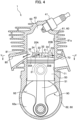
FIG. 1 is a cross-sectional view of an engine according to one embodiment of the present invention, illustrating an intake and compression process viewed from an intake passage. -
FIG. 2 is a cross-sectional side view illustrating the intake and compression process of the engine according to this embodiment. -
FIG. 3 is a cross-sectional view of the engine according to this embodiment, illustrating a scavenging process viewed from the intake passage. -
FIG. 4 is a cross-sectional side view of the engine according to this embodiment, illustrating the scavenging process. -
FIG. 5 is a cross-sectional view of the engine according to this embodiment taken on the line V-V ofFIG. 4 , illustrating the scavenging process. - An embodiment of the present invention will be described in detail below with reference to the drawings as appropriate.
- As seen in
FIG. 1 , anengine 1 according to this embodiment is a two-stroke engine used for portable power working machines such as chainsaws, brush cutters, and blowers. - The configurations of various engine mechanisms in the
engine 1 according to this embodiment are the same as those of known two-stroke engines, and thus the detailed descriptions for other than specific configurations constituting the present invention are omitted. - As seen in
FIG. 2 , theengine 1 includes a cylinder block 60 formed with acylinder 61a and acrank chamber 62a, apiston 50 slidably mounted in thecylinder 61a, and acrank shaft 90 arranged in thecrank chamber 62a. - The
engine 1 further includes anintake passage 70 leading to thecrank chamber 62a, anexhaust passage 80 leading to acombustion chamber 40, and afirst scavenging passage 10A andsecond scavenging passages 10B (seeFIG. 5 ) that make thecrank chamber 62a and thecombustion chamber 40 communicate with each other. - In the above-described
engine 1, when thepiston 50 ascends in thecylinder 61a, inside thecrank chamber 62a is negative pressured, and a mixture gas of fuel and air produced in a carburetor (not shown) fills up thecrank chamber 62a through theintake passage 70. - When the
piston 50 reaches a top dead point, a mixture gas flowed in thecylinder 61a in a scavenging process of a previous combustion cycle is compressed in thecombustion chamber 40. When the mixture gas is ignited by anignition plug 41, thepiston 50 is then pushed downwards by an expansion power of the mixture gas. - When the
piston 50 descends, as seen inFIG. 4 , theexhaust passage 80 is in communication with thecombustion chamber 40, and the post-combustion gas is exhausted to theexhaust passage 80. Further, as seen inFIG. 3 , by the descent of thepiston 50, the mixture gas filled in thecrank chamber 62a is compressed. - When the
piston 50 reaches a bottom dead point, as seen inFIG. 5 , thefirst scavenging passage 10A and thesecond scavenging passage 10B are in communication with thecombustion chamber 40, and the mixture gas flows into thecombustion chamber 40 through thefirst scavenging passage 10A and thesecond scavenging passage 10B. - As seen in
FIG. 3 , thepiston 50 reaching the bottom dead point then ascends again by the torque of thecrank shaft 90, and thus the intake and compression process is repeated. - As seen in
FIG. 1 , the cylinder block 60 is divided into acylinder head 63, an upper block 61 formed with thecylinder 61a and an upper portion of thecrank chamber 62a, and a lower case 62 formed with a lower portion of thecrank chamber 62a. The upper block 61 and the lower case 62 are assembled one above the other. - Formed on the
crank shaft 90 are acrank journal 91 rotatably supported on the lower case 62 and acrank web 92 formed on thecrank journal 91. -
Bearings 62d are fitted into inner circumferential surfaces of insertingholes 62c formed insidewall portions 62b of the lower case 62. - The
crank journal 91 is inserted into thebearings 62d, and the leading ends of the crank journal protrude outside from the lower case 62. - The
crank web 92 is coupled with thepiston 50 via a connectingrod 51, and thecrank web 92 is configured to rotate around an axis of thecrank journal 91 in response to the reciprocation of thepiston 50. - As seen in
FIG. 2 , theintake passage 70 is formed on a side portion (a right side portion inFIG. 2 ) of the upper block 61, and one end thereof is opened to a lower portion of thecylinder 61a and the other end thereof is connected to a fuel supply passage (not shown). - As seen in
FIG. 4 , anopening portion 71 of theintake passage 70 that is closer to thecylinder 61a is blocked by a side surface of thepiston 50 when thepiston 50 is positioned at the bottom dead point, and is opened, as seen inFIG. 2 , to the lower portion of thecylinder 61a communicating with thecrank chamber 62a when thepiston 50 is positioned at the top dead point. - The
exhaust passage 80 is formed on a side portion (a left side portion inFIG. 2 ) of the upper block 61 at a position opposite to theintake passage 70. One end of theexhaust passage 80 is formed with anexhaust port 81 opened to an inner circumferential surface of thecylinder 61a, and the other end thereof is connected to a muffler or silencer (not shown). - As seen in
FIG. 4 , theexhaust port 81 is in communication with thecombustion chamber 40 when thepiston 50 is positioned at the bottom dead point, and is blocked, as seen inFIG. 2 , by a side surface of thepiston 50 when thepiston 50 is positioned at the top dead point. - As seen in
FIG. 5 , thefirst scavenging passage 10A and thesecond scavenging passage 10B are formed along an axial direction of thecylinder 61a (seeFIG. 1 ) at positions lateral to thecylinder 61a (upper lateral and lower lateral inFIG. 5 ) in the upper block 61. - On a side offset from a center position P1 of the
cylinder 61a toward theexhaust port 81, thefirst scavenging passage 10A and thesecond scavenging passage 10B are formed in a pair across thecylinder 61a at positions upper and lower sides inFIG. 5 . - In this embodiment, the
first scavenging passage 10A is formed on the upper side inFIG. 5 , and thesecond scavenging passage 10B is formed on the lower side inFIG. 5 . - Further, on a side offset from the center position P1 of the
cylinder 61a toward theintake passage 70, twosecond scavenging passages cylinder 61a at positions upper and lower sides inFIG. 5 . - As seen in
FIG. 1 , thefirst scavenging passage 10A communicates with thecrank chamber 62a at a lower end portion of thefirst scavenging passage 10A. Formed on an upper end portion of thefirst scavenging passage 10A is anopening portion 11 that is opened to abottom surface 31 of afirst communication passage 30A to be described later. - It should be noted that in
FIGS. 1 and3 , thefirst scavenging passage 10A, thefirst communication passage 30A, and thefirst scavenging port 20A are depicted on the cross section of the center position of the cylinder block 60 for the purpose of easily understanding configurations of thefirst scavenging passage 10A, thefirst communication passage 30A, and thefirst scavenging port 20A. - As seen in
FIG. 1 , similar to thefirst scavenging passage 10A, thesecond scavenging passage 10B communicates with thecrank chamber 62a at a lower end portion of thesecond scavenging passage 10B (seeFIG. 1 ), and an upper end portion of thesecond scavenging passage 10B has theopening portion 11 formed to be opened to thebottom surface 31 of asecond communication passage 30B to be described later. - It should be noted that in
FIGS. 1 and3 , thesecond scavenging passage 10B, thesecond communication passage 30B, and thesecond scavenging port 20B are depicted on the cross section of the center position of the cylinder block 60 for the purpose of easily understanding configurations of thesecond scavenging passage 10B, thesecond communication passage 30B, and thesecond scavenging port 20B. - As seen in
FIG. 1 , thefirst scavenging passage 10A is formed such that an inner surface thereof located at an outer side in the radial direction of thecylinder 61a is straight along the axial direction of thecylinder 61a. Further, thefirst scavenging passage 10A is formed such that an inner surface located closer to thecylinder 61a at aposition 12 closer to thefirst communication passage 30A (the opening portion 11) is arranged more radially outside of thecylinder 61a than an inner surface located closer to thecylinder 61a at aposition 13 closer to thecrank chamber 62a. In other words, thefirst scavenging passage 10A is formed such that the inner surface located closer to thecylinder 61a at aposition 12 closer to thefirst communication passage 30A has a protrusion formed to protrude farther outward in the radial direction of thecylinder 61a than the inner surface located closer to thecylinder 61a at a position closer to thecrank chamber 62a. - This allows the cross-sectional area of the
first scavenging passage 10A in the radial direction of thecylinder 61a to be formed smaller at aposition 12 closer to thefirst communication passage 30A (the opening portion 11) than at aposition 13 closer to thecrank chamber 62a. - The
first scavenging port 20A and thesecond scavenging port 20B are opening portions each having a rectangular cross-section opened to the inner circumferential surface of thecylinder 61a (seeFIG. 4 ). - The
first scavenging port 20A and thesecond scavenging port 20B that are positioned opposite to each other across thecylinder 61a are formed at positions on both sides of the exhaust port 81 (upper side and lower side inFIG. 5 ) on a side offset from the center position P1 of thecylinder 61a toward theexhaust port 81. - In this embodiment, the first scavenging
port 20A is formed on the upper side inFIG. 5 , and thesecond scavenging port 20B is formed on the lower side inFIG. 5 . - Further, two second scavenging
ports cylinder 61a are formed at positions on both sides of theexhaust port 81 on a side offset from the center position P1 of thecylinder 61a toward theintake passage 70. - As seen in
FIG. 4 , the first scavengingport 20A and thesecond scavenging port 20B are opened to the inner circumferential surface of thecylinder 61a at about the same height as that of theexhaust port 81. - Therefore, the first scavenging
port 20A and thesecond scavenging port 20B are opened to the upper portion of thecylinder 61a and in communication with thecombustion chamber 40 when thepiston 50 is positioned at the bottom dead point. - Further, as seen in
FIG. 2 , the first scavengingport 20A and thesecond scavenging port 20B are blocked by the side surface of thepiston 50 when thepiston 50 is positioned at the top dead point. - As seen in
FIG. 5 , thefirst communication passage 30A and thesecond communication passage 30B are passageways formed in a radial direction of thecylinder 61a. - On a side offset from the center position P1 of the
cylinder 61a toward theexhaust port 81, thefirst communication passage 30A and thesecond communication passage 30B are symmetrically formed at positions upper and lower sides inFIG. 5 across thecylinder 61a. In this embodiment, thefirst communication passage 30A is formed on the upper side inFIG. 5 , and thesecond communication passage 30B is formed on the lower side inFIG. 5 . - Further, on a side offset from the center position P1 of the
cylinder 61a toward theintake passage 70, twosecond communication passages cylinder 61a at positions upper and lower sides inFIG. 5 . - An opening
portion 11 of thefirst scavenging passage 10A is opened in thebottom surface 31 of thefirst communication passage 30A. Thefirst communication passage 30A is a passageway communicating between the openingportion 11 and the first scavengingport 20A. A landing portion in the shape of landing is formed between the openingportion 11 and the first scavengingport 20A by thebottom surface 31 of thefirst communication passage 30A. The landing portion serves as a guiding surface for guiding the mixture gas from below (seeFIG. 1 ). - An opening
portion 11 of thesecond scavenging passage 10B is opened in thebottom surface 31 of thesecond communication passage 30B. Thesecond communication passage 30B is a passageway communicating between the openingportion 11 and thesecond scavenging port 20B. A landing portion in the shape of a landing is formed between the openingportion 11 and thesecond scavenging port 20B by thebottom surface 31 of thesecond communication passage 30B. The landing portion serves as a guiding surface for guiding the mixture gas from below (seeFIG. 1 ). - The
first communication passage 30A and thesecond communication passage 30B are formed from the openingportions 11 formed in the bottom surfaces 31 toward a far side from the exhaust port (hereinafter referred to as a counter-exhaust port side) that is a side opposite to the exhaust port 81 (i.e., a side closer to the intake passage 70) in the combustion chamber 40 (cylinder 61a). - Consequently, the mixture gas flowed into the
first communication passage 30A from the openingportion 11 of thefirst scavenging passage 10A is guided toward the counter-exhaust port side by thefirst communication passage 30A, and jetted (injected) in thecombustion chamber 40 in a direction toward the counter-exhaust port side from the first scavengingport 20A. - Similarly, the mixture gas flowed into the
second communication passage 30B from the openingportion 11 of thesecond scavenging passage 10B is guided toward the counter-exhaust port side by thesecond communication passage 30B, and jetted (injected) in thecombustion chamber 40 in a direction toward the counter-exhaust port side from thesecond scavenging port 20B. - As seen in
FIG. 4 , thefirst communication passage 30A has a rectangular cross-section that is formed with thebottom surface 31, both side surfaces 32, 33, and aceiling surface 34. - As seen in
FIG. 5 , among the side surfaces 32, 33 that form thefirst communication passage 30A, theside surface 33 located at the counter-exhaust port side is inclined from the outside in the radial direction of thecylinder 61a toward the first scavengingport 20A in the upper block 61 so as to be away from the other side surface 32 located closer to theexhaust port 81. In other words, theside surface 33 of thefirst communication passage 30A that is located at the counter-exhaust port side is formed directed toward the far side from the exhaust port (counter-exhaust port side) in the combustion chamber 40 (cylinder 61a). - The opening width of the
first communication passage 30A in a circumferential direction of thecylinder 61a is expanded from the openingportion 11 toward the first scavengingport 20A. - As seen in
FIG. 1 , theceiling surface 34 of thefirst communication passage 30A is inclined toward the cylinder head 63 (upper side inFIG. 1 ) with increasing distance from the openingportion 11 toward the first scavengingport 20A. - The
bottom surface 31 of thefirst communication passage 30A is inclined toward thecrank chamber 62a (lower side inFIG. 1 ) with increasing distance from the openingportion 11 toward the first scavengingport 20A. - As described above, the height of the
first communication passage 30A (i.e., width of thefirst communication passage 30A in the axial direction of thecylinder 61a) is gradually increased toward the first scavengingport 20A from a position outside in the radial direction of thecylinder 61a. - It is preferable that an inclination angle of the
bottom surface 31 of thefirst communication passage 30A toward thecrank chamber 62a is set in the range of 70 to 100% of an inclination angle of theceiling surface 34 of thefirst communication passage 30A toward thecylinder head 63. - It is preferable that the maximum height (maximum width) of the first scavenging
port 20A in the axial direction of thecylinder 61a is equal to or more than twice the minimum height (minimum width) of thefirst communication passage 30A in the axial direction of thecylinder 61a. - Further, it is preferable that a ratio of the minimum height of the
first communication passage 30A in the axial direction of thecylinder 61a to the maximum height of the first scavengingport 20A in the axial direction of thecylinder 61a is set in the range of 1:2 to 1:4. - It is preferable that the opening area of the first scavenging
port 20A is equal to or more than four times the minimum cross-sectional area of thefirst communication passage 30A in the axial direction of thecylinder 61a. - It is preferable that a ratio of the minimum cross-sectional area of the
first communication passage 30A in the axial direction of thecylinder 61a to the opening area of the first scavengingport 20A is set in the range of 1:4 to 1:8. - The
bottom surface 31 of thefirst communication passage 30A and an inner wall surface of thefirst scavenging passage 10A in the radial direction of thecylinder 61a (wall surface of thefirst scavenging passage 10A at a position closer to the first communication passage) are continuous through an arc-shapedcurved surface 35. Further, theceiling surface 34 of thefirst communication passage 30A and the inner surface of thefirst scavenging passage 10A are continuous through an arc-shapedcurved surface 36. - The
first communication passage 30A according to this embodiment is formed in a divergent form in which the cross-sectional area of the passage gradually expands from the openingportion 11 toward the first scavengingport 20A. - The cross-sectional area of the
first communication passage 30A in the axial direction of thecylinder 61a is made larger than the cross-sectional area of thefirst scavenging passage 10A in the radial direction of thecylinder 61a at aposition 12 closer to thefirst communication passage 30A (opening portion 11). - Similar to the
first communication passage 30A, as seen inFIG. 4 , thesecond communication passage 30B has a rectangular cross-section that is formed with thebottom surface 31, both side surfaces 32, 33, and aceiling surface 34. - As seen in
FIG. 5 , theside surface 33 of thesecond communication passage 30B that is located at the counter-exhaust port side is also formed directed toward the far side from the exhaust port (counter-exhaust port side) in thecombustion chamber 40. - Further, as seen in
FIG. 1 , theceiling surface 34 of thesecond communication passage 30B is also inclined toward the cylinder head 63 (upper side inFIG. 1 ) with increasing distance from the openingportion 11 toward thesecond scavenging port 20B. - The
second communication passage 30B is formed such that the cross-sectional area thereof is made larger with increasing distance from the openingportion 11 toward thesecond scavenging port 20B. The cross-sectional area of thesecond communication passage 30B in the axial direction of thecylinder 61a is made larger than the cross-sectional area of thesecond scavenging passage 10B in the radial direction of thecylinder 61a at the openingportion 11. - As seen in
FIG. 3 , according to theengine 1 of this embodiment, when thepiston 50 reaches the bottom dead point, the first scavengingport 20A and thesecond scavenging port 20B are in communication with thecombustion chamber 40. - Accordingly, the mixture gas having been filled in the
crank chamber 62a flows into thecombustion chamber 40 through thefirst scavenging passage 10A, thefirst communication passage 30A, and the first scavengingport 20A. - Further, the mixture gas having been filled in the
crank chamber 62a flows into thecombustion chamber 40 through thesecond scavenging passages 10B, thesecond communication passages 30B, and the second scavengingports 20B. - According to the
engine 1 of this embodiment, theceiling surface 34 of thefirst communication passage 30A is inclined toward thecylinder head 63 with increasing distance from the first scavenging passage side thereof to the first scavengingport 20A. Further, thebottom surface 31 of thefirst communication passage 30A is inclined toward thecrank chamber 62a with increasing distance from the first scavenging passage side thereof to the first scavengingport 20A. - With this configuration, the mixture gas compressed in the
first scavenging passage 10A is expanded to a large extent in thefirst communication passage 30A and jetted (injected) from the first scavengingport 20A into thecombustion chamber 40. The mixture gas is dispersed in thecombustion chamber 40 with respect to the axial direction of thecylinder 61a. As compared with the alternative configuration in which the width of thefirst communication passage 30A in the axial direction of thecylinder 61a is made constant, atomization of the mixture gas can be promoted upon expansion of the mixture gas and homogeneity of the component of the mixture gas can be improved within thecombustion chamber 40. This can stabilize combustion of the mixture gas. - Since the inclination angle of the
bottom surface 31 of thefirst communication passage 30A toward thecrank chamber 62a is set in the range of 70 to 100% of the inclination angle of theceiling surface 34 of thefirst communication passage 30A toward thecylinder head 63 to slightly extend thefirst communication passage 30A toward thecombustion chamber 40, the mixture gas can efficiently flow into thecombustion chamber 40. It is particularly preferable that the inclination angle of thebottom surface 31 of thefirst communication passage 30A toward thecrank chamber 62a is set to be 90% of the inclination angle of theceiling surface 34 of thefirst communication passage 30A toward thecylinder head 63. - As seen in
FIG. 5 , the opening width of thefirst communication passage 30A in the circumferential direction of thecylinder 61a is gradually expanded toward the first scavengingport 20A from a position closer to the openingportion 11 of thefirst scavenging passage 10A. - According to the
engine 1 of this embodiment, as seen inFIG. 3 , thefirst communication passage 30A is gradually expanded both in the axial direction and the circumferential direction of thecylinder 61a, from a first scavenging passage side toward the first scavengingport 20A. In other words, thefirst communication passage 30A is formed in a divergent form in which the cross-sectional area of the passage gradually expands from the openingportion 11 toward the first scavengingport 20A. - With this configuration, since the cross-sectional area of the
first communication passage 30A expands in the circumferential direction of thecylinder 61a as well as in the axial direction of thecylinder 61a, the mixture gas compressed in thefirst scavenging passage 10A is expanded to a large extent in thefirst communication passage 30A and jetted (injected) from the first scavengingport 20A into thecombustion chamber 40 so that the mixture gas can be dispersed widely in thecombustion chamber 40. This can improve the scavenging efficiency and the combustion efficiency. - As seen in
FIG. 1 , it is preferable that the maximum height (maximum width) of the first scavengingport 20A in the axial direction of thecylinder 61a is equal to or more than twice the minimum height (minimum width) of thefirst communication passage 30A in the axial direction of thecylinder 61a. - Further, it is more preferable that the ratio of the minimum height of the
first communication passage 30A in the axial direction of thecylinder 61a to the maximum height of the first scavengingport 20A in the axial direction of thecylinder 61a is set in the range of 1:2 to 1:4. - Setting the maximum height of the first scavenging
port 20A and the minimum height of thefirst communication passage 30A in this range makes it possible to efficiently improve the scavenging efficiency and the combustion efficiency. - It is preferable that the opening area of the first scavenging
port 20A is equal to or more than four times the minimum cross-sectional area of thefirst communication passage 30A in the axial direction of thecylinder 61a. - Further, it is preferable that the ratio of the minimum cross-sectional area of the
first communication passage 30A in the axial direction of thecylinder 61a to the opening area of the first scavengingport 20A is set in the range of 1:4 to 1:8. - Setting the minimum cross-sectional area of the
first communication passage 30A and the opening area of the first scavengingport 20A in this range makes it possible to efficiently improve the scavenging efficiency and the combustion efficiency. - According to the
engine 1 of this embodiment, thefirst scavenging passage 10A is formed such that the inner surface located closer to thecylinder 61a at aposition 12 closer to thefirst communication passage 30A is arranged more radially outside of thecylinder 61a than the inner surface located closer to thecylinder 61a at a position closer to the crankchamber 62a. With this configuration, thebottom surface 31 and theceiling surface 34 of thefirst communication passage 30A that serve as guiding surfaces for guiding the mixture gas are set to have sufficient lengths thereof, so that the directivity and the atomization-promoting efficiency of the mixture gas can be enhanced. Further, the cross-sectional area of thefirst scavenging passage 10A in the radial direction of thecylinder 61a is smaller at aposition 12 closer to thefirst communication passage 30A than at aposition 13 closer to the crankchamber 62a. - With this configuration, the mixture gas having flowed from the
crank chamber 62a into thefirst scavenging passage 10A is compressed in thefirst scavenging passage 10A, and then flows into thecylinder 61a while expanding in thefirst communication passage 30A. As described above, since the mixture gas is once compressed and then expanded to promote the atomization of the mixture gas and the mixture gas has directivity in the axial direction of thecylinder 61a, it is possible to scavenge the inner side of thecylinder 61a equally. Accordingly, since the mixture gas is introduced equally throughout the entire range of the inner side of thecylinder 61a, the post-combustion gas at the previous combustion cycle is swept out and discharged, and the post-combustion gas is replaced with the mixture gas required for the current combustion cycle without any waste. Therefore, the output and the response of theengine 1 can be significantly improved and the emission of unburned gas can be reduced. - Further, the cross-sectional area of the
first scavenging passage 10A in the radial direction of thecylinder 61a at aposition 12 closer to thefirst communication passage 30A is smaller than the cross-sectional area of thefirst communication passage 30A in the axial direction of thecylinder 61a. - With this configuration, the mixture gas flowed from the
first scavenging passage 10A into thefirst communication passage 30A through the openingportion 11 is once compressed in thefirst scavenging passage 10A, and then expanded in thefirst communication passage 30A. - Further, according to the
engine 1 of this embodiment, the inner surface of thefirst scavenging passage 10A and thebottom surface 31 of thefirst communication passage 30A are continuous through the arc-shapedcurved surface 35. Further, theceiling surface 34 of thefirst communication passage 30A and the inner surface of thefirst scavenging passage 10A are continuous through the arc-shapedcurved surface 36. - With this configuration, when the mixture gas flows from the
first scavenging passage 10A into thefirst communication passage 30A, the mixture gas can flow smoothly along thecurved surfaces - According to the
engine 1 of this embodiment, as seen inFIG. 5 , the side surfaces 33 of thefirst communication passage 30A and thesecond communication passage 30B that are located at the counter-exhaust port side are formed directed toward the counter-exhaust port side in thecombustion chamber 40. Further, the cylinder block 60 of theengine 1 according to this embodiment has a plurality of the scavengingports first communication passage 30A is formed, among the plurality of the scavengingports port 20A disposed closer to theexhaust port 81. - With this configuration, since the mixture gases flowed from the first scavenging
port 20A and thesecond scavenging port 20B into thecombustion chamber 40 are directed to the counter-exhaust port side, the amount of unburned mixture gas exhausted into theexhaust port 81 can be significantly reduced. - As described above, the
engine 1 according to this embodiment can significantly reduce the amount of hydrocarbon (HC) contained in the exhaust gas. - As compared with a conventional engine having no
first communication passage 30A, it was shown that theengine 1 according to this embodiment can reduce the amount of hydrocarbon contained in the exhaust gas by about 30%. - Although one preferred embodiment of the present invention has been described in detail, it is understood that the present invention is not limited to the above specific embodiment and various changes and modifications may be made where appropriate without departing from the gist and scope of the present invention.
- As seen in
FIG. 5 , theengine 1 according to this embodiment is configured such that one communication passage among four communication passages is formed in the shape of thefirst communication passage 30A. However, the number offirst communication passages 30A is not limited. For example, all of the four communication passages may be formed as thefirst communication passage 30A. - It is preferable that the configuration of the present invention is applied to one scavenging port among adjacent or opposite scavenging ports. With this configuration, since the mixture gases from scavenging ports that are arranged closely to each other flow into the
cylinder 61a with different directivities and at different speeds, the directivity of each mixture gas can be maintained while avoiding collision of the mixture gases. This can efficiently improve the scavenging efficiency and the combustion efficiency of theengine 1. - According to the
engine 1 of this embodiment, four scavenging ports are formed. However, the number of scavenging ports is not limited. For example, two scavenging ports may be formed one on each side of theexhaust port 81.
Claims (12)
- A two-stroke engine (1) comprising:a cylinder block (60) formed with a cylinder (61a) and a crank chamber (62a); anda piston (50) slidably mounted in the cylinder (61a),wherein the cylinder block (60) includes:an exhaust passage (80) leading to a combustion chamber (40) in the cylinder (61a) through an exhaust port (81) opened to an inner circumferential surface of the cylinder (61a);a scavenging port (20A) opened to the inner circumferential surface of the cylinder (61a);a communication passage (30A) extending from the scavenging port (20A) in a radial direction of the cylinder (61a); anda scavenging passage (10A) extending in an axial direction of the cylinder (61a), communicating with the crank chamber (62a), and having an opening portion (11) formed in a bottom surface (31) of the communication passage (30A), whereina ceiling surface (34) of the communication passage (30A) is inclined toward a cylinder head (63) with increasing distance from a scavenging passage side thereof toward the scavenging port (20A), anda bottom surface (31) of the communication passage (30A) is inclined toward the crank chamber (62a) with increasing distance from a scavenging passage side thereof toward the scavenging port (20A).
- The two-stroke engine (1) according to claim 1, wherein
a maximum width of the scavenging port (20A) in the axial direction of the cylinder (61a) is equal to or more than twice a minimum width of the communication passage (30A) in the axial direction of the cylinder (61a). - The two-stroke engine (1) according to claim 1, wherein
a ratio of a minimum width of the communication passage (30A) in the axial direction of the cylinder (61a) to a maximum width of the scavenging port (20A) in the axial direction of the cylinder (61a) is set in the range of 1:2 to 1:4. - The two-stroke engine (1) according to any one of claims 1 to 3, wherein
an opening area of the scavenging port (20A) is equal to or more than four times a minimum cross-sectional area of the communication passage (30A) in the axial direction of the cylinder (61a). - The two-stroke engine (1) according to any one of claims 1 to 4, wherein
a ratio of a minimum cross-sectional area of the communication passage (30A) in the axial direction of the cylinder (61a) to an opening area of the scavenging port (20A) is set in the range of 1:4 to 1:8. - The two-stroke engine (1) according to any one of claims 1 to 5, wherein
an inclination angle of the bottom surface (31) of the communication passage (30A) toward the crank chamber (62a) is set in the range of 70 to 100% of an inclination angle of the ceiling surface (34) of the communication passage (30A) toward the cylinder head (63). - The two-stroke engine (1) according to any one of claims 1 to 6, whereina cross-sectional area of the scavenging passage (10A) in the radial direction of the cylinder (61a) is smaller at a position closer to the communication passage (30A) than at a position closer to the crank chamber (62a), andthe cross-sectional area of the scavenging passage (10A) in the radial direction of the cylinder (61a) at the position closer to the communication passage (30A) is smaller than a cross-sectional area of the communication passage (30A) in the axial direction of the cylinder (61a).
- The two-stroke engine (1) according to claim 7, wherein
the scavenging passage (10A) is formed such that an inner surface located closer to the cylinder (61a) at a position closer to the communication passage (30A) is arranged more radially outside of the cylinder (61a) than an inner surface located closer to the cylinder (61a) at a position closer to the crank chamber (62a). - The two-stroke engine (1) according to any one of claims 1 to 8, wherein
an inner surface of the scavenging passage (10A) and the bottom surface (31) of the communication passage (30A) are continuous through an arc-shaped curved surface (35). - The two-stroke engine (1) according to any one of claims 1 to 9, wherein
a side surface (33) located at a counter-exhaust port side that forms the communication passage (30A) is formed directed toward the counter-exhaust port side in the combustion chamber (40). - The two-stroke engine (1) according to any one of claims 1 to 10, wherein
an opening width of the communication passage (30A) in a circumferential direction of the cylinder (61a) is gradually expanded toward the scavenging port (20A) from a position closer to the opening portion (11) of the scavenging passage (10A). - The two-stroke engine (1) according to any one of claims 1 to 11, whereinthe cylinder block (60) has a plurality of the scavenging ports (20A, 20B) and at least one the communication passage (30A), andthe communication passage (30A) is formed, among the plurality of the scavenging ports (20A, 20B), from one scavenging port (20A) disposed closer to the exhaust port (81).
Applications Claiming Priority (1)
| Application Number | Priority Date | Filing Date | Title |
|---|---|---|---|
| JP2021124482A JP2023019609A (en) | 2021-07-29 | 2021-07-29 | Two-cycle engine |
Publications (2)
| Publication Number | Publication Date |
|---|---|
| EP4124733A1 true EP4124733A1 (en) | 2023-02-01 |
| EP4124733B1 EP4124733B1 (en) | 2024-03-27 |
Family
ID=82781043
Family Applications (1)
| Application Number | Title | Priority Date | Filing Date |
|---|---|---|---|
| EP22187623.8A Active EP4124733B1 (en) | 2021-07-29 | 2022-07-28 | Two-cycle engine |
Country Status (4)
| Country | Link |
|---|---|
| US (1) | US11624337B2 (en) |
| EP (1) | EP4124733B1 (en) |
| JP (1) | JP2023019609A (en) |
| CN (1) | CN115680863A (en) |
Citations (4)
| Publication number | Priority date | Publication date | Assignee | Title |
|---|---|---|---|---|
| JP2000034927A (en) * | 1998-07-17 | 2000-02-02 | Kioritz Corp | 2-cycle internal combustion engine |
| EP1048831A2 (en) * | 1999-04-28 | 2000-11-02 | Mitsubishi Heavy Industries, Ltd. | Two-stroke cycle engine |
| US20010029912A1 (en) * | 1999-02-05 | 2001-10-18 | Franz Laimbock | Two-stroke internal combustion engine with crankcase scavenging |
| JP2009002311A (en) | 2007-06-25 | 2009-01-08 | Ihi Shibaura Machinery Corp | Two-cycle engine |
Family Cites Families (5)
| Publication number | Priority date | Publication date | Assignee | Title |
|---|---|---|---|---|
| US3797467A (en) * | 1972-02-09 | 1974-03-19 | W Tenney | Two cycle engine scavenge ports |
| JP2002276377A (en) * | 2001-03-21 | 2002-09-25 | Kioritz Corp | Two-cycle internal combustion engine |
| JP4028974B2 (en) * | 2001-09-14 | 2008-01-09 | 株式会社共立 | Method for manufacturing cylinder for internal combustion engine |
| JP5381871B2 (en) * | 2010-03-31 | 2014-01-08 | 日立工機株式会社 | Two-cycle engine and engine working machine equipped with the same |
| JP5780888B2 (en) * | 2010-12-13 | 2015-09-16 | 株式会社やまびこ | 2-cycle engine |
-
2021
- 2021-07-29 JP JP2021124482A patent/JP2023019609A/en active Pending
-
2022
- 2022-07-07 US US17/859,151 patent/US11624337B2/en active Active
- 2022-07-19 CN CN202210852179.8A patent/CN115680863A/en active Pending
- 2022-07-28 EP EP22187623.8A patent/EP4124733B1/en active Active
Patent Citations (4)
| Publication number | Priority date | Publication date | Assignee | Title |
|---|---|---|---|---|
| JP2000034927A (en) * | 1998-07-17 | 2000-02-02 | Kioritz Corp | 2-cycle internal combustion engine |
| US20010029912A1 (en) * | 1999-02-05 | 2001-10-18 | Franz Laimbock | Two-stroke internal combustion engine with crankcase scavenging |
| EP1048831A2 (en) * | 1999-04-28 | 2000-11-02 | Mitsubishi Heavy Industries, Ltd. | Two-stroke cycle engine |
| JP2009002311A (en) | 2007-06-25 | 2009-01-08 | Ihi Shibaura Machinery Corp | Two-cycle engine |
Also Published As
| Publication number | Publication date |
|---|---|
| US20230036494A1 (en) | 2023-02-02 |
| EP4124733B1 (en) | 2024-03-27 |
| US11624337B2 (en) | 2023-04-11 |
| JP2023019609A (en) | 2023-02-09 |
| CN115680863A (en) | 2023-02-03 |
Similar Documents
| Publication | Publication Date | Title |
|---|---|---|
| EP2463495B1 (en) | Two-cycle engine | |
| US6367432B1 (en) | Two-stroke cycle internal combustion engine | |
| US6513465B2 (en) | Two-stroke internal combustion engine | |
| US6640755B2 (en) | Two-cycle internal combustion engine | |
| US7243622B2 (en) | Two-stroke internal combustion engine | |
| US7255072B2 (en) | Two-stroke internal combustion engine | |
| JP5370669B2 (en) | 2-cycle engine | |
| US6450135B1 (en) | Two-stroke internal combustion engine | |
| US4236490A (en) | Internal combustion engine | |
| US4352343A (en) | Constructional improvements in a two-stroke opposed piston engine operating with stratified charge | |
| JPH02108815A (en) | Two-cycle/uniflow spark ignition engine | |
| JP4249638B2 (en) | 2-cycle engine | |
| EP4124733B1 (en) | Two-cycle engine | |
| WO2021177010A1 (en) | Two-cycle internal combustion engine and engine work machine | |
| JP3773507B2 (en) | 2-cycle internal combustion engine | |
| JP2000320338A (en) | Two-cycle internal combustion engine | |
| US7100550B2 (en) | Two-stroke engine transfer ports | |
| JP2009002311A (en) | Two-cycle engine | |
| JPH0352981Y2 (en) | ||
| JP2006348785A (en) | Two cycle internal combustion engine | |
| US20050193967A1 (en) | Sas piston channel for optimum air scavenging | |
| EP1556594B1 (en) | Two-stroke engine transfer ports | |
| JP4272001B2 (en) | 2-cycle engine | |
| JP3342483B2 (en) | Two-stroke internal combustion engine | |
| US20120006308A1 (en) | Piston for a Two-Stroke Engine |
Legal Events
| Date | Code | Title | Description |
|---|---|---|---|
| PUAI | Public reference made under article 153(3) epc to a published international application that has entered the european phase |
Free format text: ORIGINAL CODE: 0009012 |
|
| STAA | Information on the status of an ep patent application or granted ep patent |
Free format text: STATUS: THE APPLICATION HAS BEEN PUBLISHED |
|
| AK | Designated contracting states |
Kind code of ref document: A1 Designated state(s): AL AT BE BG CH CY CZ DE DK EE ES FI FR GB GR HR HU IE IS IT LI LT LU LV MC MK MT NL NO PL PT RO RS SE SI SK SM TR |
|
| STAA | Information on the status of an ep patent application or granted ep patent |
Free format text: STATUS: REQUEST FOR EXAMINATION WAS MADE |
|
| 17P | Request for examination filed |
Effective date: 20230512 |
|
| RBV | Designated contracting states (corrected) |
Designated state(s): AL AT BE BG CH CY CZ DE DK EE ES FI FR GB GR HR HU IE IS IT LI LT LU LV MC MK MT NL NO PL PT RO RS SE SI SK SM TR |
|
| GRAP | Despatch of communication of intention to grant a patent |
Free format text: ORIGINAL CODE: EPIDOSNIGR1 |
|
| STAA | Information on the status of an ep patent application or granted ep patent |
Free format text: STATUS: GRANT OF PATENT IS INTENDED |
|
| INTG | Intention to grant announced |
Effective date: 20240117 |
|
| GRAS | Grant fee paid |
Free format text: ORIGINAL CODE: EPIDOSNIGR3 |
|
| GRAA | (expected) grant |
Free format text: ORIGINAL CODE: 0009210 |
|
| STAA | Information on the status of an ep patent application or granted ep patent |
Free format text: STATUS: THE PATENT HAS BEEN GRANTED |
|
| AK | Designated contracting states |
Kind code of ref document: B1 Designated state(s): AL AT BE BG CH CY CZ DE DK EE ES FI FR GB GR HR HU IE IS IT LI LT LU LV MC MK MT NL NO PL PT RO RS SE SI SK SM TR |
|
| REG | Reference to a national code |
Ref country code: GB Ref legal event code: FG4D |
|
| REG | Reference to a national code |
Ref country code: CH Ref legal event code: EP |
|
| REG | Reference to a national code |
Ref country code: DE Ref legal event code: R096 Ref document number: 602022002550 Country of ref document: DE |
|
| REG | Reference to a national code |
Ref country code: IE Ref legal event code: FG4D |
|
| REG | Reference to a national code |
Ref country code: SE Ref legal event code: TRGR |
|
| PG25 | Lapsed in a contracting state [announced via postgrant information from national office to epo] |
Ref country code: LT Free format text: LAPSE BECAUSE OF FAILURE TO SUBMIT A TRANSLATION OF THE DESCRIPTION OR TO PAY THE FEE WITHIN THE PRESCRIBED TIME-LIMIT Effective date: 20240327 |
|
| REG | Reference to a national code |
Ref country code: LT Ref legal event code: MG9D |
|
| PG25 | Lapsed in a contracting state [announced via postgrant information from national office to epo] |
Ref country code: GR Free format text: LAPSE BECAUSE OF FAILURE TO SUBMIT A TRANSLATION OF THE DESCRIPTION OR TO PAY THE FEE WITHIN THE PRESCRIBED TIME-LIMIT Effective date: 20240628 |
|
| PG25 | Lapsed in a contracting state [announced via postgrant information from national office to epo] |
Ref country code: RS Free format text: LAPSE BECAUSE OF FAILURE TO SUBMIT A TRANSLATION OF THE DESCRIPTION OR TO PAY THE FEE WITHIN THE PRESCRIBED TIME-LIMIT Effective date: 20240627 Ref country code: HR Free format text: LAPSE BECAUSE OF FAILURE TO SUBMIT A TRANSLATION OF THE DESCRIPTION OR TO PAY THE FEE WITHIN THE PRESCRIBED TIME-LIMIT Effective date: 20240327 |
|
| PG25 | Lapsed in a contracting state [announced via postgrant information from national office to epo] |
Ref country code: RS Free format text: LAPSE BECAUSE OF FAILURE TO SUBMIT A TRANSLATION OF THE DESCRIPTION OR TO PAY THE FEE WITHIN THE PRESCRIBED TIME-LIMIT Effective date: 20240627 Ref country code: NO Free format text: LAPSE BECAUSE OF FAILURE TO SUBMIT A TRANSLATION OF THE DESCRIPTION OR TO PAY THE FEE WITHIN THE PRESCRIBED TIME-LIMIT Effective date: 20240627 Ref country code: LT Free format text: LAPSE BECAUSE OF FAILURE TO SUBMIT A TRANSLATION OF THE DESCRIPTION OR TO PAY THE FEE WITHIN THE PRESCRIBED TIME-LIMIT Effective date: 20240327 Ref country code: HR Free format text: LAPSE BECAUSE OF FAILURE TO SUBMIT A TRANSLATION OF THE DESCRIPTION OR TO PAY THE FEE WITHIN THE PRESCRIBED TIME-LIMIT Effective date: 20240327 Ref country code: GR Free format text: LAPSE BECAUSE OF FAILURE TO SUBMIT A TRANSLATION OF THE DESCRIPTION OR TO PAY THE FEE WITHIN THE PRESCRIBED TIME-LIMIT Effective date: 20240628 Ref country code: FI Free format text: LAPSE BECAUSE OF FAILURE TO SUBMIT A TRANSLATION OF THE DESCRIPTION OR TO PAY THE FEE WITHIN THE PRESCRIBED TIME-LIMIT Effective date: 20240327 Ref country code: BG Free format text: LAPSE BECAUSE OF FAILURE TO SUBMIT A TRANSLATION OF THE DESCRIPTION OR TO PAY THE FEE WITHIN THE PRESCRIBED TIME-LIMIT Effective date: 20240327 |
|
| REG | Reference to a national code |
Ref country code: NL Ref legal event code: MP Effective date: 20240327 |
|
| PG25 | Lapsed in a contracting state [announced via postgrant information from national office to epo] |
Ref country code: LV Free format text: LAPSE BECAUSE OF FAILURE TO SUBMIT A TRANSLATION OF THE DESCRIPTION OR TO PAY THE FEE WITHIN THE PRESCRIBED TIME-LIMIT Effective date: 20240327 |
|
| PG25 | Lapsed in a contracting state [announced via postgrant information from national office to epo] |
Ref country code: NL Free format text: LAPSE BECAUSE OF FAILURE TO SUBMIT A TRANSLATION OF THE DESCRIPTION OR TO PAY THE FEE WITHIN THE PRESCRIBED TIME-LIMIT Effective date: 20240327 |
|
| REG | Reference to a national code |
Ref country code: AT Ref legal event code: MK05 Ref document number: 1670113 Country of ref document: AT Kind code of ref document: T Effective date: 20240327 |
|
| PG25 | Lapsed in a contracting state [announced via postgrant information from national office to epo] |
Ref country code: NL Free format text: LAPSE BECAUSE OF FAILURE TO SUBMIT A TRANSLATION OF THE DESCRIPTION OR TO PAY THE FEE WITHIN THE PRESCRIBED TIME-LIMIT Effective date: 20240327 |
|
| PG25 | Lapsed in a contracting state [announced via postgrant information from national office to epo] |
Ref country code: IS Free format text: LAPSE BECAUSE OF FAILURE TO SUBMIT A TRANSLATION OF THE DESCRIPTION OR TO PAY THE FEE WITHIN THE PRESCRIBED TIME-LIMIT Effective date: 20240727 |
|
| PGFP | Annual fee paid to national office [announced via postgrant information from national office to epo] |
Ref country code: DE Payment date: 20240719 Year of fee payment: 3 |
|
| PG25 | Lapsed in a contracting state [announced via postgrant information from national office to epo] |
Ref country code: SM Free format text: LAPSE BECAUSE OF FAILURE TO SUBMIT A TRANSLATION OF THE DESCRIPTION OR TO PAY THE FEE WITHIN THE PRESCRIBED TIME-LIMIT Effective date: 20240327 Ref country code: PT Free format text: LAPSE BECAUSE OF FAILURE TO SUBMIT A TRANSLATION OF THE DESCRIPTION OR TO PAY THE FEE WITHIN THE PRESCRIBED TIME-LIMIT Effective date: 20240729 |
|
| PGFP | Annual fee paid to national office [announced via postgrant information from national office to epo] |
Ref country code: FR Payment date: 20240730 Year of fee payment: 3 |
|
| PG25 | Lapsed in a contracting state [announced via postgrant information from national office to epo] |
Ref country code: ES Free format text: LAPSE BECAUSE OF FAILURE TO SUBMIT A TRANSLATION OF THE DESCRIPTION OR TO PAY THE FEE WITHIN THE PRESCRIBED TIME-LIMIT Effective date: 20240327 |
|
| PG25 | Lapsed in a contracting state [announced via postgrant information from national office to epo] |
Ref country code: CZ Free format text: LAPSE BECAUSE OF FAILURE TO SUBMIT A TRANSLATION OF THE DESCRIPTION OR TO PAY THE FEE WITHIN THE PRESCRIBED TIME-LIMIT Effective date: 20240327 Ref country code: EE Free format text: LAPSE BECAUSE OF FAILURE TO SUBMIT A TRANSLATION OF THE DESCRIPTION OR TO PAY THE FEE WITHIN THE PRESCRIBED TIME-LIMIT Effective date: 20240327 |
|
| PG25 | Lapsed in a contracting state [announced via postgrant information from national office to epo] |
Ref country code: AT Free format text: LAPSE BECAUSE OF FAILURE TO SUBMIT A TRANSLATION OF THE DESCRIPTION OR TO PAY THE FEE WITHIN THE PRESCRIBED TIME-LIMIT Effective date: 20240327 |
|
| PG25 | Lapsed in a contracting state [announced via postgrant information from national office to epo] |
Ref country code: PL Free format text: LAPSE BECAUSE OF FAILURE TO SUBMIT A TRANSLATION OF THE DESCRIPTION OR TO PAY THE FEE WITHIN THE PRESCRIBED TIME-LIMIT Effective date: 20240327 |
|
| PG25 | Lapsed in a contracting state [announced via postgrant information from national office to epo] |
Ref country code: SK Free format text: LAPSE BECAUSE OF FAILURE TO SUBMIT A TRANSLATION OF THE DESCRIPTION OR TO PAY THE FEE WITHIN THE PRESCRIBED TIME-LIMIT Effective date: 20240327 |
|
| PG25 | Lapsed in a contracting state [announced via postgrant information from national office to epo] |
Ref country code: SM Free format text: LAPSE BECAUSE OF FAILURE TO SUBMIT A TRANSLATION OF THE DESCRIPTION OR TO PAY THE FEE WITHIN THE PRESCRIBED TIME-LIMIT Effective date: 20240327 Ref country code: SK Free format text: LAPSE BECAUSE OF FAILURE TO SUBMIT A TRANSLATION OF THE DESCRIPTION OR TO PAY THE FEE WITHIN THE PRESCRIBED TIME-LIMIT Effective date: 20240327 Ref country code: RO Free format text: LAPSE BECAUSE OF FAILURE TO SUBMIT A TRANSLATION OF THE DESCRIPTION OR TO PAY THE FEE WITHIN THE PRESCRIBED TIME-LIMIT Effective date: 20240327 Ref country code: PT Free format text: LAPSE BECAUSE OF FAILURE TO SUBMIT A TRANSLATION OF THE DESCRIPTION OR TO PAY THE FEE WITHIN THE PRESCRIBED TIME-LIMIT Effective date: 20240729 Ref country code: PL Free format text: LAPSE BECAUSE OF FAILURE TO SUBMIT A TRANSLATION OF THE DESCRIPTION OR TO PAY THE FEE WITHIN THE PRESCRIBED TIME-LIMIT Effective date: 20240327 Ref country code: IS Free format text: LAPSE BECAUSE OF FAILURE TO SUBMIT A TRANSLATION OF THE DESCRIPTION OR TO PAY THE FEE WITHIN THE PRESCRIBED TIME-LIMIT Effective date: 20240727 Ref country code: ES Free format text: LAPSE BECAUSE OF FAILURE TO SUBMIT A TRANSLATION OF THE DESCRIPTION OR TO PAY THE FEE WITHIN THE PRESCRIBED TIME-LIMIT Effective date: 20240327 Ref country code: EE Free format text: LAPSE BECAUSE OF FAILURE TO SUBMIT A TRANSLATION OF THE DESCRIPTION OR TO PAY THE FEE WITHIN THE PRESCRIBED TIME-LIMIT Effective date: 20240327 Ref country code: CZ Free format text: LAPSE BECAUSE OF FAILURE TO SUBMIT A TRANSLATION OF THE DESCRIPTION OR TO PAY THE FEE WITHIN THE PRESCRIBED TIME-LIMIT Effective date: 20240327 Ref country code: AT Free format text: LAPSE BECAUSE OF FAILURE TO SUBMIT A TRANSLATION OF THE DESCRIPTION OR TO PAY THE FEE WITHIN THE PRESCRIBED TIME-LIMIT Effective date: 20240327 |
|
| PGFP | Annual fee paid to national office [announced via postgrant information from national office to epo] |
Ref country code: IT Payment date: 20240731 Year of fee payment: 3 Ref country code: SE Payment date: 20240719 Year of fee payment: 3 |