EP4124728A1 - Ölwanne mit einer ölheizvorrichtung - Google Patents
Ölwanne mit einer ölheizvorrichtung Download PDFInfo
- Publication number
- EP4124728A1 EP4124728A1 EP22186539.7A EP22186539A EP4124728A1 EP 4124728 A1 EP4124728 A1 EP 4124728A1 EP 22186539 A EP22186539 A EP 22186539A EP 4124728 A1 EP4124728 A1 EP 4124728A1
- Authority
- EP
- European Patent Office
- Prior art keywords
- oil
- oil sump
- heating element
- temperature
- flow
- Prior art date
- Legal status (The legal status is an assumption and is not a legal conclusion. Google has not performed a legal analysis and makes no representation as to the accuracy of the status listed.)
- Withdrawn
Links
- 238000010438 heat treatment Methods 0.000 title claims abstract description 82
- 239000003921 oil Substances 0.000 claims abstract description 203
- 239000000839 emulsion Substances 0.000 claims abstract description 36
- 238000005461 lubrication Methods 0.000 claims abstract description 12
- 230000001052 transient effect Effects 0.000 claims abstract description 6
- 239000010687 lubricating oil Substances 0.000 claims abstract description 3
- 238000007639 printing Methods 0.000 claims description 8
- OKTJSMMVPCPJKN-UHFFFAOYSA-N Carbon Chemical compound [C] OKTJSMMVPCPJKN-UHFFFAOYSA-N 0.000 claims description 7
- 239000013528 metallic particle Substances 0.000 claims description 5
- 239000000049 pigment Substances 0.000 claims description 5
- RYGMFSIKBFXOCR-UHFFFAOYSA-N Copper Chemical compound [Cu] RYGMFSIKBFXOCR-UHFFFAOYSA-N 0.000 claims description 4
- GWEVSGVZZGPLCZ-UHFFFAOYSA-N Titan oxide Chemical compound O=[Ti]=O GWEVSGVZZGPLCZ-UHFFFAOYSA-N 0.000 claims description 3
- AYJRCSIUFZENHW-DEQYMQKBSA-L barium(2+);oxomethanediolate Chemical compound [Ba+2].[O-][14C]([O-])=O AYJRCSIUFZENHW-DEQYMQKBSA-L 0.000 claims description 3
- 239000002041 carbon nanotube Substances 0.000 claims description 3
- 229910021393 carbon nanotube Inorganic materials 0.000 claims description 3
- 229910052802 copper Inorganic materials 0.000 claims description 3
- 239000010949 copper Substances 0.000 claims description 3
- 229910021389 graphene Inorganic materials 0.000 claims description 3
- 239000002245 particle Substances 0.000 claims description 3
- 229910052709 silver Inorganic materials 0.000 claims description 3
- 239000004332 silver Substances 0.000 claims description 3
- OGIDPMRJRNCKJF-UHFFFAOYSA-N titanium oxide Inorganic materials [Ti]=O OGIDPMRJRNCKJF-UHFFFAOYSA-N 0.000 claims description 3
- 239000003292 glue Substances 0.000 claims description 2
- CURLTUGMZLYLDI-UHFFFAOYSA-N Carbon dioxide Chemical compound O=C=O CURLTUGMZLYLDI-UHFFFAOYSA-N 0.000 description 6
- 239000004952 Polyamide Substances 0.000 description 4
- 230000004907 flux Effects 0.000 description 4
- 239000000446 fuel Substances 0.000 description 4
- -1 poly(ethylene terephthalate) Polymers 0.000 description 4
- 229920002647 polyamide Polymers 0.000 description 4
- 229920000139 polyethylene terephthalate Polymers 0.000 description 4
- 239000005020 polyethylene terephthalate Substances 0.000 description 4
- BQCADISMDOOEFD-UHFFFAOYSA-N Silver Chemical compound [Ag] BQCADISMDOOEFD-UHFFFAOYSA-N 0.000 description 3
- 229910002092 carbon dioxide Inorganic materials 0.000 description 3
- 239000001569 carbon dioxide Substances 0.000 description 3
- 229940082150 encore Drugs 0.000 description 3
- 239000007787 solid Substances 0.000 description 3
- XAGFODPZIPBFFR-UHFFFAOYSA-N aluminium Chemical compound [Al] XAGFODPZIPBFFR-UHFFFAOYSA-N 0.000 description 2
- 229910052782 aluminium Inorganic materials 0.000 description 2
- 238000002485 combustion reaction Methods 0.000 description 2
- 230000006870 function Effects 0.000 description 2
- 238000007649 pad printing Methods 0.000 description 2
- 239000002861 polymer material Substances 0.000 description 2
- 238000007650 screen-printing Methods 0.000 description 2
- 239000002966 varnish Substances 0.000 description 2
- BVKZGUZCCUSVTD-UHFFFAOYSA-L Carbonate Chemical compound [O-]C([O-])=O BVKZGUZCCUSVTD-UHFFFAOYSA-L 0.000 description 1
- 235000005921 Cynara humilis Nutrition 0.000 description 1
- 240000002228 Cynara humilis Species 0.000 description 1
- 101150006573 PAN1 gene Proteins 0.000 description 1
- 241000287107 Passer Species 0.000 description 1
- 241000920340 Pion Species 0.000 description 1
- RTAQQCXQSZGOHL-UHFFFAOYSA-N Titanium Chemical compound [Ti] RTAQQCXQSZGOHL-UHFFFAOYSA-N 0.000 description 1
- 238000004026 adhesive bonding Methods 0.000 description 1
- DSAJWYNOEDNPEQ-UHFFFAOYSA-N barium atom Chemical compound [Ba] DSAJWYNOEDNPEQ-UHFFFAOYSA-N 0.000 description 1
- 239000002775 capsule Substances 0.000 description 1
- 238000001816 cooling Methods 0.000 description 1
- 230000007797 corrosion Effects 0.000 description 1
- 238000005260 corrosion Methods 0.000 description 1
- 230000007423 decrease Effects 0.000 description 1
- 230000008021 deposition Effects 0.000 description 1
- 238000010586 diagram Methods 0.000 description 1
- 230000000694 effects Effects 0.000 description 1
- 238000007641 inkjet printing Methods 0.000 description 1
- 239000000463 material Substances 0.000 description 1
- 238000000034 method Methods 0.000 description 1
- 238000012986 modification Methods 0.000 description 1
- 230000004048 modification Effects 0.000 description 1
- 239000002071 nanotube Substances 0.000 description 1
- 239000004033 plastic Substances 0.000 description 1
- 230000001681 protective effect Effects 0.000 description 1
- 229910001285 shape-memory alloy Inorganic materials 0.000 description 1
- 238000006467 substitution reaction Methods 0.000 description 1
- 230000007704 transition Effects 0.000 description 1
- 238000011144 upstream manufacturing Methods 0.000 description 1
Images

Classifications
-
- F—MECHANICAL ENGINEERING; LIGHTING; HEATING; WEAPONS; BLASTING
- F01—MACHINES OR ENGINES IN GENERAL; ENGINE PLANTS IN GENERAL; STEAM ENGINES
- F01M—LUBRICATING OF MACHINES OR ENGINES IN GENERAL; LUBRICATING INTERNAL COMBUSTION ENGINES; CRANKCASE VENTILATING
- F01M11/00—Component parts, details or accessories, not provided for in, or of interest apart from, groups F01M1/00 - F01M9/00
- F01M11/0004—Oilsumps
-
- F—MECHANICAL ENGINEERING; LIGHTING; HEATING; WEAPONS; BLASTING
- F01—MACHINES OR ENGINES IN GENERAL; ENGINE PLANTS IN GENERAL; STEAM ENGINES
- F01M—LUBRICATING OF MACHINES OR ENGINES IN GENERAL; LUBRICATING INTERNAL COMBUSTION ENGINES; CRANKCASE VENTILATING
- F01M5/00—Heating, cooling, or controlling temperature of lubricant; Lubrication means facilitating engine starting
- F01M5/02—Conditioning lubricant for aiding engine starting, e.g. heating
- F01M5/021—Conditioning lubricant for aiding engine starting, e.g. heating by heating
- F01M2005/023—Oil sump with partition for facilitating heating of oil during starting
-
- F—MECHANICAL ENGINEERING; LIGHTING; HEATING; WEAPONS; BLASTING
- F01—MACHINES OR ENGINES IN GENERAL; ENGINE PLANTS IN GENERAL; STEAM ENGINES
- F01M—LUBRICATING OF MACHINES OR ENGINES IN GENERAL; LUBRICATING INTERNAL COMBUSTION ENGINES; CRANKCASE VENTILATING
- F01M11/00—Component parts, details or accessories, not provided for in, or of interest apart from, groups F01M1/00 - F01M9/00
- F01M11/0004—Oilsumps
- F01M2011/0033—Oilsumps with special means for guiding the return of oil into the sump
-
- F—MECHANICAL ENGINEERING; LIGHTING; HEATING; WEAPONS; BLASTING
- F01—MACHINES OR ENGINES IN GENERAL; ENGINE PLANTS IN GENERAL; STEAM ENGINES
- F01M—LUBRICATING OF MACHINES OR ENGINES IN GENERAL; LUBRICATING INTERNAL COMBUSTION ENGINES; CRANKCASE VENTILATING
- F01M11/00—Component parts, details or accessories, not provided for in, or of interest apart from, groups F01M1/00 - F01M9/00
- F01M11/0004—Oilsumps
- F01M2011/0037—Oilsumps with different oil compartments
- F01M2011/0045—Oilsumps with different oil compartments for controlling the oil temperature
-
- F—MECHANICAL ENGINEERING; LIGHTING; HEATING; WEAPONS; BLASTING
- F01—MACHINES OR ENGINES IN GENERAL; ENGINE PLANTS IN GENERAL; STEAM ENGINES
- F01M—LUBRICATING OF MACHINES OR ENGINES IN GENERAL; LUBRICATING INTERNAL COMBUSTION ENGINES; CRANKCASE VENTILATING
- F01M11/00—Component parts, details or accessories, not provided for in, or of interest apart from, groups F01M1/00 - F01M9/00
- F01M11/0004—Oilsumps
- F01M2011/005—Oilsumps with special anti-turbulence means, e.g. anti-foaming means or intermediate plates
Definitions
- the present invention relates to an oil sump intended to be fixed under the engine block of an internal combustion engine.
- the main function of an oil pan is to contain the oil needed to lubricate an engine and to dissipate some of the heat generated by the engine.
- an oil sump comprises a shell which is fixed under the engine block.
- the oil present in the crankcase is sucked up by an oil pump and is propelled towards the various engine parts to be lubricated (for example, the camshafts, the valve stems, the crankshaft bearings, the piston/cylinder, piston/connecting rod, crankshaft/connecting rod, etc. interfaces), then the oil returns to the crankcase by natural runoff or by channeled return depending on the case.
- an oil pump for example, the camshafts, the valve stems, the crankshaft bearings, the piston/cylinder, piston/connecting rod, crankshaft/connecting rod, etc. interfaces
- the casing receives in its interior volume a strainer making it possible to stop the solid matter such as filings produced by the components of the engine contained in the oil before they reach the suction port of the pump, and a so-called plate anti-emulsion, whose role is to prevent or limit the movement of the oil in the crankcase, in particular on the free surface of the oil.
- the oil is heated by the engine parts and is cooled in the oil sump, when it mixes with the oil present in said sump.
- the engine components When starting the engine, the engine components are at ambient temperature. During the transitional phase of temperature rise towards the optimum operating temperature, the engine does not operate optimally and in particular the fuel consumption turns out to be significantly higher; this is due to the fact that the combustion does not take place at the optimum temperature.
- a research path aims to reduce the duration of the transitional phase of starting so that the engine reaches its optimum operating temperature as quickly as possible.
- the object of the present invention is to provide an oil sump which makes it possible to reduce the heating time of the oil of the lubrication circuit of the engine and therefore to reduce the fuel consumption when starting the engine as well as the carbon dioxide emissions.
- the invention relates to an oil sump comprising a lower shell intended to contain the lubricating oil of an engine block, in which an oil flow, called aspirated oil flow, is sucked via a suction tube to supply a lubrication circuit and an oil flow, called the returning oil flow, which falls into the oil sump.
- the oil pan includes an anti-emulsion plate disposed in the oil pan and orientation means making it possible to direct at least part of the flow of oil returning towards a zone located at the mouth of the suction tube during a transient period during which the oil has a temperature lower than an optimum temperature of functioning.
- the oil pan further includes a heater adapted to supply thermal energy to said at least a portion of the returning oil flow, said heater including at least one positive temperature coefficient heater.
- the invention provides an oil sump which makes it possible to cause the flow of oil returning to the sump (that is to say an oil flow which, in contact with the engine components that it has lubricated, is at a temperature which is higher than the temperature of the oil stored in the crankcase which is for its part at a temperature substantially equal to the ambient temperature) a short path by bringing the flow of oil returning directly to the mouth of the oil pump suction tube.
- the flow of oil returning to the sump is directly sucked up by the oil pump without having dissipated the heat which it carries in the mass of oil in the sump.
- the invention establishes a bypass of the returning oil flow to conserve the heat it contains and to directly use the returning oil flow to supply the lubrication circuit.
- the flow of oil drawn in mainly comes from the flow of oil returning from the lubrication circuit. Upon contact with engine parts, the returning oil flow rises in temperature.
- the flow of oil sucked in during the transient period mainly contains oil heated by the engine components, which accelerates the rise in temperature of the oil sucked in to its optimum operating temperature.
- the reuse in a closed loop, during the transient period, of the oil flow returning to the sucked oil flow makes it possible to accelerate the rise in temperature of the sucked oil by avoiding cooling caused by the mixing of the oil flow returning to the oil stored in the lower hull.
- the invention provides an oil sump which makes it possible to reduce the heating time of the oil of the engine lubrication circuit.
- the engine reaches its optimum operating temperature more quickly and therefore reduces the excess fuel consumption during the engine start-up phase as well as reducing carbon dioxide emissions.
- the invention also makes it possible to increase the temperature of the returning oil flow by means of a heating device integrated in the oil sump.
- the heater is configured to heat the returning oil stream before it is reinjected into the engine.
- the oil sump thus configured will further reduce the time of heats the oil in the engine's lubrication circuit and therefore reduces fuel consumption when starting the engine as well as carbon dioxide emissions.
- a heating device comprising a heating element with a positive temperature coefficient will also make it possible to prevent the oil in the lubrication circuit from exceeding the optimum operating temperature of the engine.
- the heating element with a positive temperature coefficient having a threshold temperature beyond which its resistance increases exponentially it will then be possible to choose a heating element with a positive temperature coefficient whose threshold temperature is substantially equal to optimum engine operating temperature.
- the resistance of the heating element will increase in such a way that it will greatly reduce, or even completely cancel the thermal energy supplied by the heating element, thereby stopping the increase in oil temperature.
- Self-regulation of the temperature of the oil flow returning will therefore be easily obtained by means of this heating element with a positive temperature coefficient, without the need to use temperature sensors to control the temperature of the oil returning from the engine in the oil pan.
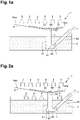
- the invention relates to an oil sump 1 intended to be fixed to an engine block.
- the oil sump 1 comprises in particular a lower shell 2, a suction tube 44 connected at one of its ends to an oil pump and which opens at its second end into the lower shell 2, an anti-emulsion plate 8 fixed on the lower shell 2 and orientation means which allow to direct a flow of oil returning.
- a strainer is positioned at the mouth of the suction tube 44 to stop solid matter such as filings produced by the engine components contained in the oil.
- the lower shell 2 is adapted to contain oil. It is open on its upper face. It may be made of polymer material or aluminum.
- the anti-emulsion plate 8 is intended to cover the upper opening of the lower shell 2.
- the anti-emulsion plate 8 may be made of polymer material or aluminum.
- An opening 87 is formed in the anti-emulsion plate 8.
- the internal walls 84a, 84b of the anti-emulsion plate 8 are inclined on either side of the opening 87 so that the opening 87 defines a low point for the anti-emulsion plate 8.
- the opening 87 is closed off by a bimetallic shutter 88 to cause it to pass from its on position to its off position.
- the bimetallic shutter 88 is movable between an open position, shown in the picture 1a , in which the opening 87 is through for oil and a closed position, represented on the figure 2a , in which the bimetallic shutter 88 closes the opening 87.
- the bimetallic shutter 88 is configured to pass into the closed position when the oil circulating on the anti-emulsion plate 8 reaches or exceeds an optimum operating temperature of the engine which is usually between 30°C and 50°C.
- the orientation means comprise a branch tube 41.
- the branch tube 41 opens at a first end into the opening 87 of the anti-emulsion plate 8 and at a second end at the mouth of the suction tube 44.
- the branch tube 41 and the suction tube 44 open into a box 45.
- the box 45 has an opening 42 allowing the oil stored in the lower shell 2 to be sucked up.
- the oil sump 1 also comprises a heating device 10 intended to heat the oil circulating on the anti-emulsion plate 8.
- this heating device 10 is formed by one or more heating elements with a temperature coefficient positive, the threshold temperature of which is substantially equal to the optimum operating temperature of the engine. This or these heating elements 10 at least partially cover the internal walls 84a, 84b of the anti-emulsion plate 8 so that the oil flowing in the direction of the opening 87 along the internal walls 84a, 84b is heated by heating elements 10.
- the bimetallic shutter 88 When the engine is started, the bimetallic shutter 88 is in the open position because the oil has not yet reached its optimum temperature. Returning oil flow II flows predominantly through opening 87. Returning oil flow II flowing through opening 87 passes through branch tube 41 and flows to the mouth of the tube suction 44 where it is sucked and becomes the sucked oil stream I.
- the aspirated flow of oil I which passes through the suction tube 44 mainly contains oil coming directly from the engine having already heated in contact with the engine elements, but also in contact with the heating device 10.
- the bimetallic shutter 88 switches to the closed position and the heating device 10 ceases to heat the flow of returning oil II.
- all the returning oil flow II flows into the lower hull 2 through other outlets (not shown) of the anti-emulsion plate 8 which are located at a higher level with respect to the opening 87
- the aspirated flow of oil I then comes from the lower shell 2 and passes through the opening 42 of the box 45 to cross the suction tube 44.
- the active orientation means allowing the orientation of the returning oil flow II consist of a bimetallic shutter 88 arranged at the level of the opening 87.
- these active orientation means may be supplemented or replaced by bimetallic shutters arranged at the level of the other outlet orifices (mentioned above) of the anti-emulsion plate 8. These bimetallic shutters will be movable between a closed position in which they will close said outlet ports and an open position in which oil can flow through said outlet ports. These shutters will be configured to switch to the open position when the oil reaches or exceeds the optimum operating temperature for the engine.
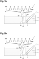
- the oil sump 1 comprises in particular a lower shell 2, a suction tube 44 connected at one of its ends to an oil pump and which opens at its second end into the lower shell 2, an anti-emulsion plate 8 fixed on the lower shell 2 and orientation means which allow to direct a flow of oil returning.
- a strainer is positioned at the mouth of the suction tube 44 to stop solid matter such as filings produced by the engine components contained in the oil.
- This second embodiment differs from that represented on the figures 1a and 2a by the fact that the opening 87 is not closed by a bimetallic shutter and by the fact that the branch tube 41 is provided with an opening 89 communicating the interior of the branch tube 41 with the lower shell 2
- a bimetallic shutter 88 is arranged at the level of opening 89.
- This bimetallic shutter 88 is movable between a closed position, represented on the figure 1b , in which the bimetallic shutter 88 closes the opening 89, and an open position, represented on the figure 2b , in which the opening 89 is through for oil.
- the bimetallic shutter 88 is configured to switch to the open position when the oil circulating in the bypass tube reaches or exceeds an optimum engine operating temperature which is usually between 30°C and 50°C.
- the bimetallic shutter 88 When the engine is started, the bimetallic shutter 88 is in the closed position because the oil has not yet reached its optimum temperature. Returning oil flow II flows predominantly through opening 87, then along bypass tube 41. Returning oil flow II circulating in bypass tube 41 then flows to the mouth of the suction tube 44 where it is sucked and becomes the sucked oil stream I.
- the aspirated flow of oil I which passes through the suction tube 44 mainly contains oil coming directly from the engine having already heated in contact with the engine elements, but also in contact with the heating device 10.
- the bimetallic shutter 88 switches to the open position and the heating device 10 ceases to heat the flow of returning oil II.
- all the returning oil flow II flows into the lower hull 2 through the opening 89 of the bypass tube 41.
- the sucked oil flow I then comes from the lower hull 2 and passes through the opening 42 of the housing 45 to pass through the suction tube 44.
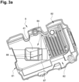
- This anti-emulsion plate 8 has in particular a collection portion 81.
- the collection portion 81 has two flanges 82.
- the fixing of the anti-emulsion plate 8 to the lower shell 2 can for example be carried out with bolts or rivets.
- the collection portion 81 comprises a bottom wall 84 offset in the direction of the bottom of the lower shell 2 with respect to the flanges 82.
- An oil passage opening 87 is made in the bottom wall 84. This opening 87 communicates with a branch tube 41 disposed under the anti-emulsion plate 8.
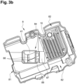
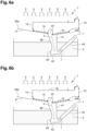
- the branch tube 41 is provided with several openings 89 (as shown in the figure 3b ).
- these openings 89 are closed off by a bimetal shutter 88 whereas, in the position represented on the figure 3b , these openings 89 are conductive, the bimetal shutter 88 having undergone a deformation under the effect of the hot oil circulating inside the bypass tube 41 and whose temperature is greater than a threshold temperature usually between 30 °C and 50°C
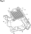
- a heating device 10 consisting of a substantially flat heating element is fixed to the bottom wall 84 so as to cover it almost entirely, leaving however the opening 87 visible.
- the fixing of the heating element 10 on the bottom wall 84 can be effected by riveting by means of centering pins 86 fitting into fixing holes 13 of the heating element 10.
- this heating element 10 may also be glued to the bottom wall 84 or printed directly on the latter, for example by a printing technique chosen from screen printing, pad printing or jet printing. ink.
- This heating element 10 may in particular be covered with a protective varnish to prevent corrosion linked to the environment (oil and oil vapor) in which this heating element will be immersed or its damage during transport or handling of this casing. .
- This varnish may be made from poly(ethylene terephthalate) (PET) or polyamide (PA).
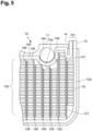
- This heating element 10 is formed of a flexible and electrically insulating base support 11, for example made of plastic material, in particular based on poly(ethylene terephthalate) (PET ) or polyamide (PA), on which two conductive tracks 12, 14 have been deposited, namely a so-called “negative” conductive track 12 and a so-called “positive” conductive track 14.
- PET poly(ethylene terephthalate)
- PA polyamide
- the deposition can in particular be carried out by printing a conductive ink, the conductive ink comprising metallic particles, such as silver or copper particles.
- Each conductive track 12, 14 is formed of a main track, respectively 120, 140, and of a plurality of secondary tracks, respectively 121-126 and 141-146, extending parallel from each conductive track 12, 14.
- Each secondary track 121-126 of negative conductive track 12 is parallel and adjacent to a secondary track 141-146 of positive conductive track 14.
- Each pair of mutually adjacent secondary tracks of the negative and positive conductive tracks (e.g. the pair of secondary 124-143 on the picture 3 ) is connected by means of a plurality of resistive strips 15.
- Each resistive strip 15 advantageously consists at least partially of an ink with a positive temperature coefficient, the ink being able to be printed on the base support 10 by screen printing, pad printing or inkjet printing.
- the positive temperature coefficient ink may for example comprise a pigment chosen from barium carbonate, titanium oxide, carbon nanotubes or graphene.
- This type of pigment in fact gives the ink an electrical resistance which increases exponentially with the temperature when the temperature to which the ink is subjected exceeds a threshold temperature. In practice, this threshold temperature is between 50°C and 150°C.
- the heating element 10 is in the form of a flexible printed circuit whose negative and positive conductive tracks 12, 14 extend from an end zone 101 to a heating zone 102 formed mainly by the secondary tracks 121-126, 141-146 connected by conductive strips 15.
- Each conductive track 12, 14 will be supplied with electric current via an electrical connection terminal (not shown), respectively negative and positive, electrically connected to the conductive tracks 12, 14 at the level of the end zone 101 and intended to be electrically connected to a source of electric power.
- a source of electric power connected to terminals + and - causes an electric current i to pass in conductive tracks 12 and 14 through resistor R formed by heating device 10.
- the resistance R of the heater 10 increases due to the characteristics of the positive temperature coefficient heating element and, therefore, the heat P transmitted by the device heating device 10 decreases inversely proportionally: self-regulation of the heating power delivered by the heating device 10 is thus achieved.
- the bimetallic shutter 88 switches to the open position to close the bypass tube 41 and the flow of oil II, which was previously redirected to flow d
- the sucked oil I now flows directly into the lower shell 2, bypassing the bypass tube 41.
- switch means 16 are provided between the electric power source and the heating device 10. These switch means 16 are intended to control the supply of electric current i to the heating device 10 depending on oil flow temperature II.
- these switch means consist of a bimetallic shutter 16 movable between an open position, as shown on the figure 6a , in which the heater 10 is not electrically connected to the source of electrical power and a closed position in which the heater 10 is electrically connected to the source of electrical power, thus resulting in a substantially identical operating diagram to that shown on the figure 6a .
- the bimetallic shutter 16 will advantageously be configured to switch to the open position when the temperature of the oil flow II reaches or exceeds the optimum operating temperature of the engine.
- these switch means 16 may consist of an electric switch capable of passing from an open state to a closed state under the control of a control unit, said control unit being capable of controlling the electrical switch according to a temperature value measured by a temperature sensor which will be in contact with the flow of oil II flowing along the anti-emulsion plate 8.
- the heating device 10 is arranged inside the suction tube 44 downstream of the housing 45
- the heating device 10 it will also be possible to arrange the heating device 10 inside the branch tube 41 upstream of the box 45 or in the box 45 itself.
- this heating device 10 consists, before its attachment to the internal periphery of the suction tube 44, of a flexible U-shaped flat support, having two lateral branches 12, 14 defined by the negative and positive conductive tracks and by a heating zone 102 between the side branches 12, 14, said heating zone 102 being formed by a plurality of resistive strips 15 each formed by printing an ink with a positive temperature coefficient, the negative and positive conductive tracks being electrically connected by means of said resistive strips 15. Due to its flexibility, the heating device 10 can roll up on itself so as to bring the side branches 12, 14 closer together, the heating zone 102 then having a substantially cylindrical shape, as represented on the figure 7 , which will facilitate its attachment to the inner periphery of the suction tube 44. This attachment may in particular take place by gluing, riveting or clipping.
Landscapes
- Engineering & Computer Science (AREA)
- Mechanical Engineering (AREA)
- General Engineering & Computer Science (AREA)
- Lubrication Of Internal Combustion Engines (AREA)
- Lubrication Details And Ventilation Of Internal Combustion Engines (AREA)
Applications Claiming Priority (1)
| Application Number | Priority Date | Filing Date | Title |
|---|---|---|---|
| FR2108104A FR3125556B1 (fr) | 2021-07-26 | 2021-07-26 | Carter d'huile comprenant un dispositif de chauffage d'huile |
Publications (1)
| Publication Number | Publication Date |
|---|---|
| EP4124728A1 true EP4124728A1 (de) | 2023-02-01 |
Family
ID=77411959
Family Applications (1)
| Application Number | Title | Priority Date | Filing Date |
|---|---|---|---|
| EP22186539.7A Withdrawn EP4124728A1 (de) | 2021-07-26 | 2022-07-22 | Ölwanne mit einer ölheizvorrichtung |
Country Status (2)
| Country | Link |
|---|---|
| EP (1) | EP4124728A1 (de) |
| FR (1) | FR3125556B1 (de) |
Citations (7)
| Publication number | Priority date | Publication date | Assignee | Title |
|---|---|---|---|---|
| US20090277416A1 (en) * | 2008-05-09 | 2009-11-12 | Toyota Boshoku Kabushiki Kaisha | Diluting fuel-in-oil separating apparatus of internal combustion engine |
| US20120006622A1 (en) * | 2009-03-19 | 2012-01-12 | Ino8 Pty Ltd. | Method and apparatus for oiling rotating or oscillating components |
| DE102012020282A1 (de) * | 2012-10-17 | 2014-04-17 | Daimler Ag | Schmiermittelbehältnis für ein Aggregat eines Kraftwagens |
| US20140353230A1 (en) * | 2013-06-03 | 2014-12-04 | Mann+Hummel Gmbh | Filter with heating medium and filter element of a filter |
| DE102013013309A1 (de) * | 2013-08-12 | 2015-02-12 | Mann + Hummel Gmbh | Behältnis für Fluid mit einer Heizeinrichtung |
| DE102016216359A1 (de) * | 2016-08-30 | 2018-03-01 | Bayerische Motoren Werke Aktiengesellschaft | Antriebseinrichtung für ein Kraftfahrzeug |
| FR3057610A1 (fr) * | 2016-10-18 | 2018-04-20 | Mecaplast France | Carter d'huile |
-
2021
- 2021-07-26 FR FR2108104A patent/FR3125556B1/fr active Active
-
2022
- 2022-07-22 EP EP22186539.7A patent/EP4124728A1/de not_active Withdrawn
Patent Citations (7)
| Publication number | Priority date | Publication date | Assignee | Title |
|---|---|---|---|---|
| US20090277416A1 (en) * | 2008-05-09 | 2009-11-12 | Toyota Boshoku Kabushiki Kaisha | Diluting fuel-in-oil separating apparatus of internal combustion engine |
| US20120006622A1 (en) * | 2009-03-19 | 2012-01-12 | Ino8 Pty Ltd. | Method and apparatus for oiling rotating or oscillating components |
| DE102012020282A1 (de) * | 2012-10-17 | 2014-04-17 | Daimler Ag | Schmiermittelbehältnis für ein Aggregat eines Kraftwagens |
| US20140353230A1 (en) * | 2013-06-03 | 2014-12-04 | Mann+Hummel Gmbh | Filter with heating medium and filter element of a filter |
| DE102013013309A1 (de) * | 2013-08-12 | 2015-02-12 | Mann + Hummel Gmbh | Behältnis für Fluid mit einer Heizeinrichtung |
| DE102016216359A1 (de) * | 2016-08-30 | 2018-03-01 | Bayerische Motoren Werke Aktiengesellschaft | Antriebseinrichtung für ein Kraftfahrzeug |
| FR3057610A1 (fr) * | 2016-10-18 | 2018-04-20 | Mecaplast France | Carter d'huile |
Also Published As
| Publication number | Publication date |
|---|---|
| FR3125556A1 (fr) | 2023-01-27 |
| FR3125556B1 (fr) | 2024-03-29 |
Similar Documents
| Publication | Publication Date | Title |
|---|---|---|
| EP3080523B1 (de) | Elektrische vorrichtung zur thermischen konditionierung der flüssigkeit für ein kraftfahrzeug und entsprechende heiz- und/oder lüftungsvorrichtung | |
| FR3057610B1 (fr) | Carter d'huile | |
| EP3471978B1 (de) | Kühlmittelkreislauf für fahrzeug | |
| FR2800125A1 (fr) | Dispositif de distribution et de regulation d'un liquide de refroidissement dans un circuit de refroidissement d'un moteur a combustion interne et son procede | |
| WO2008145461A1 (fr) | Module pour un circuit de refroidissement d'un moteur de vehicule automobile | |
| WO1984000578A1 (fr) | Dispositif de refroidissement d'un moteur a combustion interne | |
| EP2901088B1 (de) | Vorrichtung zur thermischen flüssigkeitskonditionierung für ein kraftfahrzeug sowie entsprechende heiz- und/oder klimaanlagenvorrichtung | |
| EP0567402A1 (de) | Vorrichtung für die Heizung und Lüftung des Innenraums von Motorfahrzeugen mit geringer Wärmeabgabe des Motors | |
| EP0292531A1 (de) | Elektrischer konvektionsheizer mit zwei arbeitsgängen | |
| EP3223581B1 (de) | Scheibenwischer für fahrzeug | |
| EP1438499A1 (de) | Brennstoffeinspritzsystem mit rückführung für dieselmotoren | |
| EP4124728A1 (de) | Ölwanne mit einer ölheizvorrichtung | |
| WO2005094965A1 (fr) | Systeme de filtration de liquide comprenant des moyens de chauffage de liquide | |
| EP3861419B1 (de) | Thermostatisches ventil und fahrzeug mit diesem ventil | |
| EP4186149B1 (de) | Elektromotor und antriebssystem zur wärmeübertragung | |
| FR3105709A1 (fr) | Dispositif de régulation thermique | |
| EP2892743B1 (de) | Vorrichtung zur elektrischen erwärmung einer flüssigkeit für ein kraftfahrzeug und zugehöriger heizkreislauf sowie heiz-und/oder klimaanlage | |
| FR2717961A1 (fr) | Machine électrique et démarreur de véhicule automobile comportant des moyens de protection contre la surchauffe. | |
| EP3849833B1 (de) | Wärmetransferflüssigkeitskreislauf | |
| FR2851315A1 (fr) | Vanne de regulation d'un fluide equipee d'un dispositif de chauffage | |
| WO2022268581A1 (fr) | Dispositif de régulation thermique d'au moins un composant électrique et/ou électronique | |
| FR3008032A1 (fr) | Dispositif de conditionnement thermique de fluide pour vehicule automobile et appareil de chauffage et/ou de climatisation correspondant | |
| FR3085438A1 (fr) | Embouchure d'ejection d'un gaz chaud a travers une paroi de moteur d'aeronef | |
| FR2878316A1 (fr) | Dispositif de chauffage electrique, notamment pour appareil de chauffage, de ventilation et/ou de climatisation de vehicule | |
| FR2556414A1 (fr) | Moteur a combustion interne avec assistance au demarrage |
Legal Events
| Date | Code | Title | Description |
|---|---|---|---|
| PUAI | Public reference made under article 153(3) epc to a published international application that has entered the european phase |
Free format text: ORIGINAL CODE: 0009012 |
|
| STAA | Information on the status of an ep patent application or granted ep patent |
Free format text: STATUS: THE APPLICATION HAS BEEN PUBLISHED |
|
| AK | Designated contracting states |
Kind code of ref document: A1 Designated state(s): AL AT BE BG CH CY CZ DE DK EE ES FI FR GB GR HR HU IE IS IT LI LT LU LV MC MK MT NL NO PL PT RO RS SE SI SK SM TR |
|
| P01 | Opt-out of the competence of the unified patent court (upc) registered |
Effective date: 20230526 |
|
| STAA | Information on the status of an ep patent application or granted ep patent |
Free format text: STATUS: THE APPLICATION IS DEEMED TO BE WITHDRAWN |
|
| 18D | Application deemed to be withdrawn |
Effective date: 20230802 |