EP4124574B1 - Mehrmotorsystem und leistungsübertragung zwischen seinen motoren - Google Patents
Mehrmotorsystem und leistungsübertragung zwischen seinen motoren Download PDFInfo
- Publication number
- EP4124574B1 EP4124574B1 EP22186942.3A EP22186942A EP4124574B1 EP 4124574 B1 EP4124574 B1 EP 4124574B1 EP 22186942 A EP22186942 A EP 22186942A EP 4124574 B1 EP4124574 B1 EP 4124574B1
- Authority
- EP
- European Patent Office
- Prior art keywords
- engine
- core shaft
- shaft
- gearbox
- power
- Prior art date
- Legal status (The legal status is an assumption and is not a legal conclusion. Google has not performed a legal analysis and makes no representation as to the accuracy of the status listed.)
- Active
Links
Images


Classifications
-
- B—PERFORMING OPERATIONS; TRANSPORTING
- B64—AIRCRAFT; AVIATION; COSMONAUTICS
- B64D—EQUIPMENT FOR FITTING IN OR TO AIRCRAFT; FLIGHT SUITS; PARACHUTES; ARRANGEMENT OR MOUNTING OF POWER PLANTS OR PROPULSION TRANSMISSIONS IN AIRCRAFT
- B64D35/00—Transmitting power from power plants to propellers or rotors; Arrangements of transmissions
- B64D35/02—Transmitting power from power plants to propellers or rotors; Arrangements of transmissions specially adapted for specific power plants
- B64D35/021—Transmitting power from power plants to propellers or rotors; Arrangements of transmissions specially adapted for specific power plants for electric power plants
- B64D35/022—Transmitting power from power plants to propellers or rotors; Arrangements of transmissions specially adapted for specific power plants for electric power plants of hybrid-electric type
- B64D35/024—Transmitting power from power plants to propellers or rotors; Arrangements of transmissions specially adapted for specific power plants for electric power plants of hybrid-electric type of series type
-
- B—PERFORMING OPERATIONS; TRANSPORTING
- B64—AIRCRAFT; AVIATION; COSMONAUTICS
- B64C—AEROPLANES; HELICOPTERS
- B64C27/00—Rotorcraft; Rotors peculiar thereto
- B64C27/04—Helicopters
- B64C27/12—Rotor drives
-
- B—PERFORMING OPERATIONS; TRANSPORTING
- B64—AIRCRAFT; AVIATION; COSMONAUTICS
- B64D—EQUIPMENT FOR FITTING IN OR TO AIRCRAFT; FLIGHT SUITS; PARACHUTES; ARRANGEMENT OR MOUNTING OF POWER PLANTS OR PROPULSION TRANSMISSIONS IN AIRCRAFT
- B64D27/00—Arrangement or mounting of power plants in aircraft; Aircraft characterised by the type or position of power plants
- B64D27/02—Aircraft characterised by the type or position of power plants
- B64D27/10—Aircraft characterised by the type or position of power plants of gas-turbine type
- B64D27/14—Aircraft characterised by the type or position of power plants of gas-turbine type within, or attached to, fuselages
-
- B—PERFORMING OPERATIONS; TRANSPORTING
- B64—AIRCRAFT; AVIATION; COSMONAUTICS
- B64D—EQUIPMENT FOR FITTING IN OR TO AIRCRAFT; FLIGHT SUITS; PARACHUTES; ARRANGEMENT OR MOUNTING OF POWER PLANTS OR PROPULSION TRANSMISSIONS IN AIRCRAFT
- B64D33/00—Arrangement in aircraft of power plant parts or auxiliaries not otherwise provided for
-
- F—MECHANICAL ENGINEERING; LIGHTING; HEATING; WEAPONS; BLASTING
- F01—MACHINES OR ENGINES IN GENERAL; ENGINE PLANTS IN GENERAL; STEAM ENGINES
- F01D—NON-POSITIVE DISPLACEMENT MACHINES OR ENGINES, e.g. STEAM TURBINES
- F01D13/00—Combinations of two or more machines or engines
- F01D13/003—Combinations of two or more machines or engines with at least two independent shafts, i.e. cross-compound
-
- F—MECHANICAL ENGINEERING; LIGHTING; HEATING; WEAPONS; BLASTING
- F01—MACHINES OR ENGINES IN GENERAL; ENGINE PLANTS IN GENERAL; STEAM ENGINES
- F01D—NON-POSITIVE DISPLACEMENT MACHINES OR ENGINES, e.g. STEAM TURBINES
- F01D15/00—Adaptations of machines or engines for special use; Combinations of engines with devices driven thereby
- F01D15/10—Adaptations for driving, or combinations with, electric generators
-
- F—MECHANICAL ENGINEERING; LIGHTING; HEATING; WEAPONS; BLASTING
- F02—COMBUSTION ENGINES; HOT-GAS OR COMBUSTION-PRODUCT ENGINE PLANTS
- F02C—GAS-TURBINE PLANTS; AIR INTAKES FOR JET-PROPULSION PLANTS; CONTROLLING FUEL SUPPLY IN AIR-BREATHING JET-PROPULSION PLANTS
- F02C3/00—Gas-turbine plants characterised by the use of combustion products as the working fluid
- F02C3/04—Gas-turbine plants characterised by the use of combustion products as the working fluid having a turbine driving a compressor
- F02C3/107—Gas-turbine plants characterised by the use of combustion products as the working fluid having a turbine driving a compressor with two or more rotors connected by power transmission
-
- F—MECHANICAL ENGINEERING; LIGHTING; HEATING; WEAPONS; BLASTING
- F02—COMBUSTION ENGINES; HOT-GAS OR COMBUSTION-PRODUCT ENGINE PLANTS
- F02C—GAS-TURBINE PLANTS; AIR INTAKES FOR JET-PROPULSION PLANTS; CONTROLLING FUEL SUPPLY IN AIR-BREATHING JET-PROPULSION PLANTS
- F02C6/00—Plural gas-turbine plants; Combinations of gas-turbine plants with other apparatus; Adaptations of gas-turbine plants for special use
- F02C6/02—Plural gas-turbine plants having a common power output
-
- F—MECHANICAL ENGINEERING; LIGHTING; HEATING; WEAPONS; BLASTING
- F02—COMBUSTION ENGINES; HOT-GAS OR COMBUSTION-PRODUCT ENGINE PLANTS
- F02C—GAS-TURBINE PLANTS; AIR INTAKES FOR JET-PROPULSION PLANTS; CONTROLLING FUEL SUPPLY IN AIR-BREATHING JET-PROPULSION PLANTS
- F02C7/00—Features, components parts, details or accessories, not provided for in, or of interest apart form groups F02C1/00 - F02C6/00; Air intakes for jet-propulsion plants
- F02C7/32—Arrangement, mounting, or driving, of auxiliaries
-
- F—MECHANICAL ENGINEERING; LIGHTING; HEATING; WEAPONS; BLASTING
- F02—COMBUSTION ENGINES; HOT-GAS OR COMBUSTION-PRODUCT ENGINE PLANTS
- F02C—GAS-TURBINE PLANTS; AIR INTAKES FOR JET-PROPULSION PLANTS; CONTROLLING FUEL SUPPLY IN AIR-BREATHING JET-PROPULSION PLANTS
- F02C7/00—Features, components parts, details or accessories, not provided for in, or of interest apart form groups F02C1/00 - F02C6/00; Air intakes for jet-propulsion plants
- F02C7/36—Power transmission arrangements between the different shafts of the gas turbine plant, or between the gas-turbine plant and the power user
-
- B—PERFORMING OPERATIONS; TRANSPORTING
- B64—AIRCRAFT; AVIATION; COSMONAUTICS
- B64C—AEROPLANES; HELICOPTERS
- B64C27/00—Rotorcraft; Rotors peculiar thereto
- B64C27/04—Helicopters
- B64C27/12—Rotor drives
- B64C27/14—Direct drive between power plant and rotor hub
-
- F—MECHANICAL ENGINEERING; LIGHTING; HEATING; WEAPONS; BLASTING
- F05—INDEXING SCHEMES RELATING TO ENGINES OR PUMPS IN VARIOUS SUBCLASSES OF CLASSES F01-F04
- F05D—INDEXING SCHEME FOR ASPECTS RELATING TO NON-POSITIVE-DISPLACEMENT MACHINES OR ENGINES, GAS-TURBINES OR JET-PROPULSION PLANTS
- F05D2220/00—Application
- F05D2220/30—Application in turbines
- F05D2220/32—Application in turbines in gas turbines
- F05D2220/329—Application in turbines in gas turbines in helicopters
-
- F—MECHANICAL ENGINEERING; LIGHTING; HEATING; WEAPONS; BLASTING
- F05—INDEXING SCHEMES RELATING TO ENGINES OR PUMPS IN VARIOUS SUBCLASSES OF CLASSES F01-F04
- F05D—INDEXING SCHEME FOR ASPECTS RELATING TO NON-POSITIVE-DISPLACEMENT MACHINES OR ENGINES, GAS-TURBINES OR JET-PROPULSION PLANTS
- F05D2220/00—Application
- F05D2220/70—Application in combination with
- F05D2220/76—Application in combination with an electrical generator
-
- F—MECHANICAL ENGINEERING; LIGHTING; HEATING; WEAPONS; BLASTING
- F05—INDEXING SCHEMES RELATING TO ENGINES OR PUMPS IN VARIOUS SUBCLASSES OF CLASSES F01-F04
- F05D—INDEXING SCHEME FOR ASPECTS RELATING TO NON-POSITIVE-DISPLACEMENT MACHINES OR ENGINES, GAS-TURBINES OR JET-PROPULSION PLANTS
- F05D2240/00—Components
- F05D2240/60—Shafts
-
- F—MECHANICAL ENGINEERING; LIGHTING; HEATING; WEAPONS; BLASTING
- F05—INDEXING SCHEMES RELATING TO ENGINES OR PUMPS IN VARIOUS SUBCLASSES OF CLASSES F01-F04
- F05D—INDEXING SCHEME FOR ASPECTS RELATING TO NON-POSITIVE-DISPLACEMENT MACHINES OR ENGINES, GAS-TURBINES OR JET-PROPULSION PLANTS
- F05D2260/00—Function
- F05D2260/40—Transmission of power
- F05D2260/402—Transmission of power through friction drives
- F05D2260/4023—Transmission of power through friction drives through a friction clutch
-
- F—MECHANICAL ENGINEERING; LIGHTING; HEATING; WEAPONS; BLASTING
- F05—INDEXING SCHEMES RELATING TO ENGINES OR PUMPS IN VARIOUS SUBCLASSES OF CLASSES F01-F04
- F05D—INDEXING SCHEME FOR ASPECTS RELATING TO NON-POSITIVE-DISPLACEMENT MACHINES OR ENGINES, GAS-TURBINES OR JET-PROPULSION PLANTS
- F05D2260/00—Function
- F05D2260/40—Transmission of power
- F05D2260/403—Transmission of power through the shape of the drive components
- F05D2260/4031—Transmission of power through the shape of the drive components as in toothed gearing
Definitions
- the disclosure relates generally to multi-engine systems for aircrafts and methods of controlling such systems.
- Multi-engine aircrafts such as helicopters are often provided with two or more turboshaft gas turbine engines connected to a main rotor via a common gearbox, and each of the engines is typically capable of providing power greater than what is required for cruising using both/all engines.
- both engines typically operate at similar power output levels (e.g. each engine provides 50% of the total power output).
- Attempts have however been made to operate the engines asymmetrically, that is, operating one engine at a higher power than the other. Doing so can provide overall better fuel efficiency.
- the engine operating at lower power needs to be able to rapidly speed back up, when called upon. While such systems are suitable for their intended purposes, improvements are desirable.
- a prior art multi-engine system for an aircraft having the features of the preamble of claim 1, is disclosed in EP 2963247 A2 . Further prior art multi-engine systems are disclosed in EP 2602458 A1 and US 2015/322864 A1 .
- the multi-engine system defined above and described herein may also include one or more of the following features, in whole or in part, and in any combination.
- the transmission path further comprises an electrical connection between the first electric machine operable as a generator and the second electric machine operable as an electric motor to transmit electrical power generated by the first electric machine to the second electric machine to drive the second core shaft.
- the first electric machine is drivingly engaged by the first core shaft.
- the first set of VGVs 36A upstream of the LP compressor 12 may be mechanically decoupled from the second set of VGVs 36B upstream of the HP compressor 14 and downstream of the LP compressor 12, having no mechanical link between the two sets of VGVs to permit independent operation of the respective stages.
- the VGVs 36 may be operatively controlled by the controller(s) 29 described above, to be operated independently of each other. Indeed, the turboshaft engine 10 is also controlled using controller(s) 29 described above, to carry out the methods described in this document.
- the term "independently" in respects of the VGVs 36 means that the position of one set of the VGV vanes (e.g. 36A) may be set without effecting any change to a position of the other set of the VGV vanes (e.g. 36B), and vice versa.
- Independent control of the VGVs 36 may allow the spools 26, 28 to be operated to reduce or eliminate or reduce aerodynamic coupling between the spools 26, 28. This may permit the spools 26, 28 to be operated at a wider range of speeds than may otherwise be possible.
- the independent control of the VGVs 36 may allow the spools 26, 28 to be operated at constant speed over a wider operating range, such as from a "standby" speed to a "cruise" power speed, or a higher speed.
- independent control of the VGVs 36 may allow the spools 26, 28 to run at speeds close to maximum power.
- independent control of the VGVs 36 may also allow one of the spools 26, 28 to run at high speed while the other one run at low speed.
- the speed of the engine 10 is controlled, at least in part, by the delivery of a desired fuel flow rate (e.g., a rate of change of a fuel flow) to the engine, with a lower fuel flow rate causing the turboshaft engine 10 to operate at a lower output speed than a higher fuel flow rate.
- a desired fuel flow rate e.g., a rate of change of a fuel flow
- the control of the VGVs 36 may provide for improved stability of engine operation. This may be so even where the VGVs 36 is operated at an extreme end of their ranges, such as in the "closed down" position (e.g. at a position of +80 degrees in one embodiment described herein).
- This control of the VGVs 36 may facilitate the ability of the turboshaft engine 10 to operate at a very low power setting, such as may be associated with a "standby" mode as described further below herein, wherein the compressor of an engine operating in standby mode is operating in a very low flow and/or low pressure ratio regime.
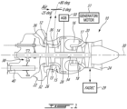
- the multi-engine system 42 includes two or more engines 10A, 10B.
- the two engines 10A, 10B drive a common load via a reduction gearbox 46 and an output shaft 60.
- Clutches 61, 62 may be used to selectively engage and disengage output shafts 48, 40A, 40B of the engines 10A, 10B to the reduction gearbox 46.
- these engines 10A, 10B will be turboshaft engines such as the turboshaft engine 10 described above with reference to Fig. 1 . They may alternatively be any suitable gas turbine engines.
- the engines 10A, 10B of the system 42 may be operated asymmetrically, with one engine operated in a high-power "active” mode and the other engine operated in a lower-power "standby” mode. Doing so may provide fuel saving opportunities to the aircraft, however there may be other suitable reasons why the engines are desired to be operated asymmetrically.
- This operation management may therefore be referred to as an "asymmetric mode” or an “asymmetric operating regime", wherein one of the two engines is operated in a low-power "standby mode" while the other engine is operated in a high-power "active” mode.
- the multi-engine system 42 may be used in an aircraft, such as a helicopter , but also has applications in suitable marine and/or industrial applications or other ground operations.
- the multi-engine system 42 driving a helicopter (H) may be operated in this asymmetric manner, in which a first of the turboshaft engines (say, 10A) may be operated at high power in an active mode and the second of the turboshaft engines, for instance the engine 10B in this example, may be operated in a low-power standby mode.
- the first turboshaft engine 10A may be controlled by the controller(s) 29 to run at full (or near-full) power conditions in the active mode, to supply substantially all or all of a required power and/or speed demand of the common load 44.
- an asymmetric operating regime of the engines may be achieved through the one or more controller's 29 differential control of fuel flow to the engines, as described in US 2020/0049025 A1 .
- Low fuel flow may also include zero fuel flow in some examples.
- the controller 29 may operate one engine, for instance the engine 10B, of the multiengine system 42 in a standby mode at a power substantially lower than a rated cruise power level of the engine, and in some embodiments at zero output power and in other embodiments less than 10% output power relative to a reference power (provided at a reference fuel flow).
- the controller(s) 29 may control the standby engine to operate at a power in a range of 0% to 1% of a rated full-power of the standby engine (i.e. the power output of the second engine to the common gearbox remains between 0% to 1% of a rated full-power of the second engine when the second engine is operating in the standby mode).
- asymmetric mode is applicable to more than two engines, whereby at least one of the multiple engines is operated in a low-power standby mode while the remaining engines are operated in the active mode to supply all or substantially all of a required power and/or speed demand of a common load.
- the first turboshaft engine (say 10A) may operate in the active mode while the other turboshaft engine, such as the engine 10B, may operate in the standby mode, as described above.
- the second turboshaft engine 10B may be required to provide more power relative to the low power conditions of the standby mode, and possibly return immediately to a high- or full-power condition. This may occur, for example, in an emergency condition of the multi-engine system 42 powering the helicopter, wherein the "active" engine loses power the power recovery from the lower power to the high power may take some time. Even absent an emergency, it will be desirable to repower the standby engine to exit the asymmetric mode.
- the current disclosure describes systems and methods for coupling the two engines 10A, 10B independently of a reduction gearbox 46 used to drive the main rotor 44. This may provide fuel savings and may reduce recovery time of the low-power engine from the stand-by or low-power mode to the high-power mode.
- the first engine 10A includes a first AGB 50A and a first motor/generator 51A.
- the first motor/generator 51A is drivingly engaged to the HP shaft 34 of the first engine 10A via the first AGB 50A.
- the first motor/generator 51A may alternatively be drivingly engaged to the LP shaft 32 of the first engine 10A via the first AGB 50A.
- the second engine 10B includes a second AGB 50B and a second motor/generator 51B.
- the second motor/generator 51B is drivingly engaged to the HP shaft 34 of the second engine 10B via the second AGB 50B.
- the second motor/generator 51B may alternatively be drivingly engaged to the LP shaft 32 of the second engine 10B via the second AGB 50B.
- each of the engines 10A, 10B has its HP shaft 34 rotating independently from its LP shaft 32.
- the first engine 10A may be operated in a normal or high-power mode whereas the second engine 10B may be operated in idle or a low-power mode. At some point, it may be required to operable both of the engines 10A, 10B in the high-power mode for driving the main rotor 44. This may be required, for instance, if a sudden acceleration is required.
- the multi-engine system 42 shown in Fig. 2 has a transmission path between the first engine 10A and the second engine 10B that is independent from the reduction gearbox 46 that combines rotational inputs of the LP shafts 32 of the two engines 10A, 10B to drive the main rotor 44 or any other common load.
- the transmission path may be used to allow the first engine 10A to transfer energy to the second engine 10B to help accelerating the second engine 10B to operate it in the high-power mode. This may be done by transmitting a torque from the first engine 10A to the second engine 10B and optionally by transmitting electrical power from the first engine 10A to the second engine 10B.
- the transmission path includes a torque-transfer connection between the HP shaft 34 of the second engine 10B and either one of the HP shaft 34 (connection shown with a solid line in Fig. 2 ) of the first engine 10A and the LP shaft 32 (connection shown with a dashed line in Fig. 2 ) of the first engine 10A.
- one or more of the LP shaft 32 and the HP shaft 34 of the first engine 10A may drive the HP shaft 34 of the second engine 10B.
- the torque-transfer connection is therefore a transfer of torque from a shaft of the first engine 10A to the HP shaft 34 of the second engine 10B to spool up rotation of the second engine 10B for faster response time.
- a coupling gearbox 52 is used to drivingly engage the shafts. More detail about this coupling gearbox 52 are provided below.
- the transmission path may additionally include an electrical connection (dashed line) between the first motor/generator 51A of the first engine 10A, which is operated as a generator, to the second motor/generator 51B of the second engine 10B, which is then operated as an electric motor.
- the first and second motor/generator 51A, 51B may be operatively connected to the controller 29, which may calibrate how much power is being transmitted between the first and second motor/generators 51A, 51B to minimize fuel consumption of the second engine 10B when it is being operated in the low-power mode.
- the coupling gearbox 52 includes a first load path P1 and a second load path P2 being independent from one another such that a rotational input may be transmitted from the first input/output 52A to the second input/output 52B solely via the first load path P1 and that a rotational input may be transmitted from the second input/output 52B to the first input/output 52A solely via the second load path P2.
- the first and second load paths P1, P2 are parallel and independent from one another.
- the sixth gear 55F has a greater diameter than the fourth gear 55D and a greater diameter than the fifth gear 55E.
- the second gear 55B is meshed with a seventh gear 55G having a greater diameter than the second gear 55B.
- the seventh gear 55G is coaxial with an eighth gear 55H having a smaller diameter than the seventh gear 55G.
- the eighth gear 55H is meshed with the third gear 55C.
- the eighth gear 55H has a smaller diameter than the third gear 55C.
- the first load path P1 extends from the first gear 55A to the third gear 55C via the second gear 55B, the seventh gear 55G meshed with the second gear 55B, and the eighth gear 55H meshed with the third gear 55C.
- the second load path P2 extends from the third gear 55C to the first gear 55A via the fourth gear 55D, the sixth gear 55F meshed with the fourth gear 55D, and the fifth gear 55E meshed with the first gear 55A.
- the first load path P1 includes a first one-way clutch 56A disposed between the seventh gear 55G and the eighth gear 55h.
- the first one-way clutch 56A allows torque transfer from the first gear 55A to the third gear 55C by permitting a torque transfer from the seventh gear 55G to the eighth gear 55H.
- the first one-way clutch 56A does not allow torque transfer from the third gear 55C to the first gear 55A via the seventh gear 55G and the eighth gear 55H.
- the second load path P2 includes a second one-way clutch 56B disposed between the fifth gear 55E and the sixth gear 55F.
- the second one-way clutch 56B allows torque transfer from the third gear 55C to the first gear 55A by permitting a torque transfer from the sixth gear 55F to the fifth gear 55E.
- the second one-way clutch 56B does not allow torque transfer from the first gear 55A to the third gear 55C via the fifth gear 55E and the sixth gear 55F.
- the one-way clutches may be sprag clutches or any other suitable devices that allow torque transfer in a single direction.
- first one-way clutch 56A may be located between the first input/output 52A and the first gear 55A.
- the second one-way clutch 56B may be located between the second input/output 52B and the third gear 55C.
- the one-way clutches 56A, 56B could be located at gears 55A and 55C instead of gears 55F and 55G. This may allow running the gears 55E, 55F, 55F and 55G at lower speed when the load path is not passing through them.
- These alternate locations of the first and second one-way clutches 56A, 56B are shown in dashed lines in Fig. 4 with reference numerals 56A' and 56B'.
- the coupling gearbox 52 may be considered as a bi-direction de-multiplication gearbox since it may allow the permutation of which of the two engines 10A, 10B is being operated as the high-power engine. This may ensure that both of the engines 10A, 10B wear at a common rate by being either the high or the low power engine alternatively, from flight to flight.
- This coupling gearbox 52 may ensure that the HP shaft 34 of either engine is rotating at a speed at least equal or greater than a given reduction ratio of the speed of the other engine. That reduction ratio is determined based on the required engine recovery time, which may depend of the engine architecture.
- the one-way clutches 56A, 56B may ensure the torque is only able to transfer from the high power engine to the low power engine, when this latter would have tend normally to operate (with the amount of fuel flow provided, or in absence of fuel flow) at a HP shaft speed lower than the high power HP spool time the reduction ratio.
- a fuel flow provided to the low-power engine may be zero.
- the low-power engine may not consume fuel at all when operated in the low-power mode because its HP shaft 34 is driven by the high-power engine.
- the coupling gearbox 52 may be used to create a speed ratio between the HP shafts 34 of the two engines 10A, 10B.
- the first engine 10A which is operated in the high-power mode, may be run at 100% while the second engine 10B operated in the low-power mode may be run at 50% speed. This may allow to even further reduce the amount of fuel required to keep the low power engine running or completely cut the fuel flow and maintain the engine ready for a fast emergency start-up.
- the electrical power fed to the second engine 10B may be used to reduce a fuel consumption of the second engine 10B required to keep the second engine 10B running.
- the fuel flow to the second engine 10B may be cut and the electrical power may be used to maintain a given rotational speed of the HP shaft 34 of the second engine 10B for fast emergency start-up.
- the required amount of electrical energy may be harvested from the first engine 10A, which is operated in the high-power mode, and/or fed into the second engine 10B, and a control system (e.g., controller 29) may be used to stop/start/balance this electrical energy transfer in the manner most likely to reduce fuel consumption for the low power engine and/or limit power penalties for the high power engine.
- a control system e.g., controller 29
- the low-power engine may use a bypass flow path to avoid the air from flowing through the LP compressor 12.
- the VGVs may be used to seal the main gas path to force the air through the bypass flow path.
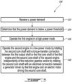
- the method 500 includes receiving a power demand at 502; determining that the power demand is below a power threshold at 504; operating the first engine 10A in a high-power mode at 506; and operating the second engine 10B in a low-power mode by rotating the HP shaft 34 of the second engine 10B with a torque-transfer connection between the LP shaft 32 or the HP shaft 34 of the first engine 10A and the HP shaft 34 of the second engine 10B independently of the reduction gearbox 46 and optionally by rotating the HP shaft 34 of the second engine 10B with an electrical connection between the first motor/generator 51A operated as a generator driven by the first engine 10A and the second motor/generator 51B operated as an electric motor driving the HP shaft 34 of the second engine 10B at 508.
- the HP shaft 34 of the second engine 10B may be rotated at a different rotational speed than the HP shaft 34 of the first engine 10A.
- the clutch 53 may be engaged to drivingly engage the LP or HP shafts 32, 34 of the first engine 10A to the HP shaft 34 of the second engine 10B through the clutch 53.
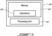
- the controller 29 may be implemented with one or more computing devices 600.
- the controller 29 can be implemented as part of a full-authority digital engine controls (FADEC) or other similar device, including electronic engine control (EEC), engine control unit (ECU), electronic propeller control, propeller control unit, and the like.
- FADEC full-authority digital engine controls
- EEC electronic engine control
- ECU engine control unit
- propeller control propeller control unit
- the controller 29 is implemented as a Flight Data Acquisition Storage and Transmission system, such as a FAST TM system.
- the controller 29 may be implemented in part in the FAST TM system and in part in the EEC. Other embodiments may also apply.
- the computing device 600 comprises a processing unit 602 and a memory 604 which has stored therein computer-executable instructions 606.
- the processing unit 602 may comprise any suitable devices configured to implement the method 500 such that instructions 606, when executed by the computing device 600 or other programmable apparatus, may cause the functions/acts/steps performed as part of the method 500 as described herein to be executed.
- the processing unit 602 may comprise, for example, any type of general-purpose microprocessor or microcontroller, a digital signal processing (DSP) processor, a central processing unit (CPU), an integrated circuit, a field programmable gate array (FPGA), a reconfigurable processor, other suitably programmed or programmable logic circuits, or any combination thereof.
- DSP digital signal processing
- CPU central processing unit
- FPGA field programmable gate array
- reconfigurable processor other suitably programmed or programmable logic circuits, or any combination thereof.
- the memory 604 may comprise any suitable known or other machine-readable storage medium.
- the memory 604 may comprise non-transitory computer readable storage medium, for example, but not limited to, an electronic, magnetic, optical, electromagnetic, infrared, or semiconductor system, apparatus, or device, or any suitable combination of the foregoing.
- the memory 604 may include a suitable combination of any type of computer memory that is located either internally or externally to device, for example random-access memory (RAM), read-only memory (ROM), compact disc read-only memory (CDROM), electro-optical memory, magneto-optical memory, erasable programmable read-only memory (EPROM), and electrically-erasable programmable read-only memory (EEPROM), Ferroelectric RAM (FRAM) or the like.
- Memory 604 may comprise any storage means (e.g., devices) suitable for retrievably storing machine-readable instructions 606 executable by processing unit 602.
- the methods and systems for operating the multi-engine system described herein may be implemented in a high level procedural or object oriented programming or scripting language, or a combination thereof, to communicate with or assist in the operation of a computer system, for example the computing device 600.
- the methods and systems for operating the multi-engine system may be implemented in assembly or machine language.
- the language may be a compiled or interpreted language.
- Program code for implementing the methods and systems for operating the multi-engine system may be stored on a storage media or a device, for example a ROM, a magnetic disk, an optical disc, a flash drive, or any other suitable storage media or device.
- the program code may be readable by a general or special-purpose programmable computer for configuring and operating the computer when the storage media or device is read by the computer to perform the procedures described herein.
- Embodiments of the methods and systems for operating the multi-engine system may also be considered to be implemented by way of a non-transitory computer-readable storage medium having a computer program stored thereon.
- the computer program may comprise computer-readable instructions which cause a computer, or more specifically the processing unit 602 of the computing device 600, to operate in a specific and predefined manner to perform the functions described herein, for example those described in the method 500.
- Computer-executable instructions may be in many forms, including program modules, executed by one or more computers or other devices.
- program modules include routines, programs, objects, components, data structures, etc., that perform particular tasks or implement particular abstract data types.
- functionality of the program modules may be combined or distributed as desired in various embodiments.
- the embodiments described herein are implemented by physical computer hardware, including computing devices, servers, receivers, transmitters, processors, memory, displays, and networks.
- the embodiments described herein provide useful physical machines and particularly configured computer hardware arrangements.
- the embodiments described herein are directed to electronic machines and methods implemented by electronic machines adapted for processing and transforming electromagnetic signals which represent various types of information.
- the embodiments described herein pervasively and integrally relate to machines, and their uses; and the embodiments described herein have no meaning or practical applicability outside their use with computer hardware, machines, and various hardware components. Substituting the physical hardware particularly configured to implement various acts for non-physical hardware, using mental steps for example, may substantially affect the way the embodiments work.
- connection or “coupled to” may include both direct coupling (in which two elements that are coupled to each other contact each other) and indirect coupling (in which at least one additional element is located between the two elements).
Landscapes
- Engineering & Computer Science (AREA)
- Mechanical Engineering (AREA)
- Chemical & Material Sciences (AREA)
- Combustion & Propulsion (AREA)
- General Engineering & Computer Science (AREA)
- Aviation & Aerospace Engineering (AREA)
- Hybrid Electric Vehicles (AREA)
- Supercharger (AREA)
- Output Control And Ontrol Of Special Type Engine (AREA)
Claims (14)
- Mehrmotorsystem (42) für ein Luftfahrzeug, umfassend:einen ersten Motor (10A), der eine erste Ausgangswelle (32) und eine erste Kernwelle (34) aufweist;einen zweiten Motor (10), der eine zweite Ausgangswelle (32) und eine zweite Kernwelle (34) aufweist;ein Untersetzungsgetriebe (46), das zum Antreiben einer gemeinsamen Last (44) mit der ersten Ausgangswelle (32) und mit der zweiten Ausgangswelle (32) in Antriebseingriff steht; undeinen Übertragungspfad zwischen dem ersten Motor (10A) und dem zweiten Motor (10B), wobei der Übertragungspfad unabhängig von dem Untersetzungsgetriebe (48) ist, wobei der Übertragungspfad eine Drehmomentübertragungsverbindung zwischen der zweiten Kernwelle (34) und der ersten Kernwelle (34) oder der ersten Ausgangswelle (32) über ein Kupplungsgetriebe (52) ist,dadurch gekennzeichnet, dass:der erste Motor (10A) eine erste elektrische Maschine (51A) aufweist, die als Generator betreibbar ist, wobei die erste elektrische Maschine (51A) mit der ersten Ausgangswelle (32) oder der ersten Kernwelle (34) in Antriebseingriff steht;der zweite Motor (10) eine zweite elektrische Maschine (51B) aufweist, die als Elektromotor betreibbar ist, wobei die zweite elektrische Maschine (51B) mit der zweiten Kernwelle (34) in Antriebseingriff steht; unddas Kupplungsgetriebe (52) einen ersten Lastpfad (P1) und einen zweiten Lastpfad (P2) aufweist, wobei der zweite Lastpfad (P2) unabhängig von dem ersten Lastpfad (P1) ist, und das Kupplungsgetriebe (52) umkehrbar ist, sodass die erste Kernwelle (34) und/oder die erste Ausgangswelle (32) die zweite Kernwelle (34) über den ersten Lastpfad (P1) antreibt und die zweite Kernwelle (34) die erste Kernwelle (34) über den zweiten Lastpfad (P2) antreibt.
- Mehrmotorsystem nach Anspruch 1, wobei der Übertragungspfad ferner eine elektrische Verbindung zwischen der als Generator betreibbaren ersten elektrischen Maschine (51A) und der als Elektromotor betreibbaren zweiten elektrischen Maschine (51B) umfasst, um von der ersten elektrischen Maschine (51A) erzeugte elektrische Leistung zum Antreiben der zweiten Kernwelle (34) an die zweite elektrische Maschine (51B) zu übertragen.
- Mehrmotorsystem nach Anspruch 1 oder 2, wobei die erste elektrische Maschine (51A) mit der ersten Kernwelle (34) in Antriebseingriff steht.
- Mehrmotorsystem nach einem der vorhergehenden Ansprüche, wobei die Drehmomentübertragungsverbindung zwischen der zweiten Kernwelle (34) und der ersten Kernwelle (34) über das Kupplungsgetriebe (52) besteht.
- Mehrmotorsystem nach einem der vorhergehenden Ansprüche, wobei die erste Kernwelle (34) über ein erstes Hilfsgetriebe (50A) mit der ersten elektrischen Maschine (51A) in Antriebseingriff steht und die zweite Kernwelle (34) über ein zweites Hilfsgetriebe (50B) mit der zweiten elektrischen Maschine (51B) in Antriebseingriff steht.
- Mehrmotorsystem nach Anspruch 5, wobei die Drehmomentübertragungsverbindung zwischen dem ersten Hilfsgetriebe (50A) und dem zweiten Hilfsgetriebe (50B) über das Kupplungsgetriebe (52) besteht.
- Mehrmotorsystem nach einem der vorhergehenden Ansprüche, wobei der erste Lastpfad (P1) eine erste Freilaufkupplung (56A) und der zweite Lastpfad (P2) eine zweite Freilaufkupplung (56B) beinhaltet.
- Mehrmotorsystem nach einem der vorhergehenden Ansprüche, umfassend eine Kupplung (53) zwischen der zweiten Kernwelle (34) und der ersten Kernwelle (34) oder der ersten Ausgangswelle (32), wobei die Kupplung (53) in einer eingerückten und ausgerückten Konfiguration zum selektiven Einrücken bzw. Ausrücken der Drehmomentübertragungsverbindung betreibbar ist.
- Verfahren zum Betreiben eines Mehrmotorsystems (42) für ein Luftfahrzeug, das einen ersten Motor (10A) und einen zweiten Motor (10B) aufweist, wobei der erste Motor (10A) eine erste Ausgangswelle (32) und eine erste Kernwelle (34) aufweist, der zweite Motor (10B) eine zweite Ausgangswelle (32) und eine zweite Kernwelle (34) aufweist, wobei die erste Ausgangswelle (32) und die zweite Ausgangswelle (32) über ein Untersetzungsgetriebe (46) mit einer gemeinsamen Last (44) in Antriebseingriff stehen, wobei das Verfahren Folgendes umfasst:Empfangen einer Leistungsanforderung;Bestimmen, dass der Leistungsbedarf unter einem Leistungsschwellenwert liegt;Betreiben des ersten Motors (10A) in einem Hochleistungsmodus; undBetreiben des zweiten Motors (10B) in einem Niedrigleistungsmodus durch Drehen der zweiten Kernwelle (34) mit einer Drehmomentübertragungsverbindung zwischen der ersten Ausgangswelle (32) oder der ersten Kernwelle (34) des ersten Motors (10A) und der zweiten Kernwelle (34) des zweiten Motors (10B) über ein Kupplungsgetriebe (52) unabhängig von dem Untersetzungsgetriebe (46),dadurch gekennzeichnet, dass:
das Kupplungsgetriebe (52) einen ersten Lastpfad (P1) und einen zweiten Lastpfad (P2) aufweist, wobei der zweite Lastpfad (P2) unabhängig von dem ersten Lastpfad (P1) ist, und das Kupplungsgetriebe (52) umkehrbar ist, sodass die erste Kernwelle (34) und/oder die erste Ausgangswelle (32) die zweite Kernwelle (34) über den ersten Lastpfad (P1) antreibt und die zweite Kernwelle (34) die erste Kernwelle (34) über den zweiten Lastpfad (P2) antreibt. - Verfahren nach Anspruch 9, wobei das Betreiben des zweiten Motors (10B) in dem Niedrigleistungsmodus Drehen der zweiten Kernwelle (34) mit einer elektrischen Verbindung zwischen einem von dem ersten Motor (10A) angetriebenen Generator (51A) und einem die zweite Kernwelle (34) antreibenden Elektromotor (51B) beinhaltet.
- Verfahren nach Anspruch 10, wobei das Drehen der zweiten Kernwelle (34) mit der elektrischen Verbindung Antriebseingreifen des Generators (51A) in die erste Ausgangswelle (32) oder die erste Kernwelle (34) über ein erstes Hilfsgetriebe (50A) und Antriebseingreifen der zweiten Kernwelle (34) in den Elektromotor (51B) über ein zweites Hilfsgetriebe (50B) beinhaltet.
- Verfahren nach Anspruch 9, 10 oder 11, wobei das Drehen der zweiten Kernwelle (34) mit der Drehmomentübertragungsverbindung Antriebseingreifen der ersten Ausgangswelle (32) oder der ersten Kernwelle (34) in die zweite Kernwelle (34) über ein erstes oder das erste Hilfsgetriebe (50A) und über ein zweites oder das zweite mit dem ersten Hilfsgetriebe (50A) über das Kupplungsgetriebe (52) in Antriebseingriff stehende(s) Hilfsgetriebe (50B) beinhaltet.
- Verfahren nach einem der Ansprüche 9 bis 12, ferner umfassend Antreiben der zweiten Kernwelle (34) mit einer anderen Drehzahl als die der ersten Kernwelle (34).
- Verfahren nach einem der Ansprüche 9 bis 13, ferner umfassend Einrücken einer Kupplung (53) aus einer ausgerückten Konfiguration in eine eingerückte Konfiguration zum Antriebseingreifen der ersten Ausgangswelle (32) oder der ersten Kernwelle (34) durch die Kupplung (53) in die zweite Kernwelle (34).
Applications Claiming Priority (1)
| Application Number | Priority Date | Filing Date | Title |
|---|---|---|---|
| US17/390,205 US11905888B2 (en) | 2021-07-30 | 2021-07-30 | Multi-engine system and power transfer between engines thereof |
Publications (2)
| Publication Number | Publication Date |
|---|---|
| EP4124574A1 EP4124574A1 (de) | 2023-02-01 |
| EP4124574B1 true EP4124574B1 (de) | 2025-03-12 |
Family
ID=82742950
Family Applications (1)
| Application Number | Title | Priority Date | Filing Date |
|---|---|---|---|
| EP22186942.3A Active EP4124574B1 (de) | 2021-07-30 | 2022-07-26 | Mehrmotorsystem und leistungsübertragung zwischen seinen motoren |
Country Status (4)
| Country | Link |
|---|---|
| US (1) | US11905888B2 (de) |
| EP (1) | EP4124574B1 (de) |
| CA (1) | CA3168061A1 (de) |
| PL (1) | PL4124574T3 (de) |
Families Citing this family (1)
| Publication number | Priority date | Publication date | Assignee | Title |
|---|---|---|---|---|
| FR3153598B1 (fr) * | 2023-10-02 | 2025-10-03 | Safran Helicopter Engines | Système de propulsion d’un aéronef, aeronef et helicoptere comportant un tel système de propulsion et procede de commande d’un système de propulsion |
Family Cites Families (19)
| Publication number | Priority date | Publication date | Assignee | Title |
|---|---|---|---|---|
| US2723531A (en) | 1947-07-21 | 1955-11-15 | Solar Aircraft Co | Auxiliary power supply device for aircraft and constant speed drive mechanism therefor |
| GB1389403A (en) * | 1971-06-01 | 1975-04-03 | Westland Aircraft Ltd | Helicopter power transmission systems |
| US4270408A (en) | 1978-10-13 | 1981-06-02 | General Motors Corporation | Gear drive for gas turbine engine |
| JP3029976B2 (ja) * | 1995-01-27 | 2000-04-10 | 株式会社コミュータヘリコプタ先進技術研究所 | ヘリコプタの動力伝達装置 |
| US6488469B1 (en) | 2000-10-06 | 2002-12-03 | Pratt & Whitney Canada Corp. | Mixed flow and centrifugal compressor for gas turbine engine |
| US7296767B2 (en) * | 2005-05-31 | 2007-11-20 | Sikorsky Aircraft Corporation | Variable speed transmission for a rotary wing aircraft |
| US8169100B2 (en) * | 2008-01-30 | 2012-05-01 | Pratt & Whitney Canada Corp. | Torque transmission for an aircraft engine |
| US9267438B2 (en) * | 2011-10-11 | 2016-02-23 | Pratt & Whitney Canada Corp. | Starting of aircraft engine |
| US9429077B2 (en) * | 2011-12-06 | 2016-08-30 | Pratt & Whitney Canada Corp. | Multiple turboshaft engine control method and system for helicopters |
| US8939399B2 (en) * | 2012-07-31 | 2015-01-27 | Textron Innovations Inc. | System and method of augmenting power in a rotorcraft |
| US10850863B2 (en) | 2014-03-04 | 2020-12-01 | Pratt & Whitney Canada Corp. | System and method for operating a multi-engine aircraft in an auxiliary power unit mode |
| US10066547B2 (en) * | 2014-07-01 | 2018-09-04 | United Technologies Corporation | Combined two engine cycle with at least one recuperated cycle engine for rotor drive |
| WO2016049030A1 (en) * | 2014-09-23 | 2016-03-31 | Sikorsky Aircraft Corporation | Hybrid contingency power drive system |
| WO2016168340A1 (en) * | 2015-04-15 | 2016-10-20 | Sikorsky Aircraft Corporation | Systems and methods for starting an engine |
| US10400858B2 (en) | 2016-06-09 | 2019-09-03 | Pratt & Whitney Canada Corp. | Reduction gearbox for aircraft engine |
| US11415044B2 (en) * | 2018-06-19 | 2022-08-16 | Raytheon Technologies Corporation | Multi-engine architecture with linkages to multiple spools |
| EP4339440A3 (de) | 2018-08-08 | 2024-05-22 | Pratt & Whitney Canada Corp. | Mehrmotorsystem und verfahren |
| US11663863B2 (en) | 2019-06-07 | 2023-05-30 | Pratt & Whitney Canada Corp. | Methods and systems for operating a rotorcraft |
| US11104430B2 (en) * | 2019-09-27 | 2021-08-31 | Textron Innovations Inc. | Multimode powertrains for multi engine rotorcraft |
-
2021
- 2021-07-30 US US17/390,205 patent/US11905888B2/en active Active
-
2022
- 2022-07-15 CA CA3168061A patent/CA3168061A1/en active Pending
- 2022-07-26 PL PL22186942.3T patent/PL4124574T3/pl unknown
- 2022-07-26 EP EP22186942.3A patent/EP4124574B1/de active Active
Also Published As
| Publication number | Publication date |
|---|---|
| US11905888B2 (en) | 2024-02-20 |
| CA3168061A1 (en) | 2023-01-30 |
| EP4124574A1 (de) | 2023-02-01 |
| US20230034946A1 (en) | 2023-02-02 |
| PL4124574T3 (pl) | 2025-06-02 |
Similar Documents
| Publication | Publication Date | Title |
|---|---|---|
| US12098644B2 (en) | Turboshaft gas turbine engine | |
| EP3693583B1 (de) | System und verfahren zum betrieb von motoren eines flugzeugs in einem asymmetrischen betriebsmodus | |
| US11725597B2 (en) | System and method for exiting an asymmetric engine operating regime | |
| US20230096526A1 (en) | Aircraft power plant with a transmission to drive an electrical machine | |
| EP4124574B1 (de) | Mehrmotorsystem und leistungsübertragung zwischen seinen motoren | |
| EP3978739A1 (de) | Verfahren und system zur steuerung eines motors bei niedriger leistung | |
| EP3770406B1 (de) | Kraftstoffzuführsystem und -verfahren | |
| EP3770404B1 (de) | Kraftstoffzuführsystem und -verfahren | |
| EP4130451B1 (de) | Schneller motorneustart für ein mehrmotoriges system und verfahren | |
| EP4123149A1 (de) | Gasturbinenmotor mit niederdruckverdichter-bypass | |
| EP3770405B1 (de) | Kraftstoffzuführsystem und -verfahren | |
| EP4123125A2 (de) | Abdichtung verstellbarer leitschaufeln |
Legal Events
| Date | Code | Title | Description |
|---|---|---|---|
| PUAI | Public reference made under article 153(3) epc to a published international application that has entered the european phase |
Free format text: ORIGINAL CODE: 0009012 |
|
| STAA | Information on the status of an ep patent application or granted ep patent |
Free format text: STATUS: THE APPLICATION HAS BEEN PUBLISHED |
|
| AK | Designated contracting states |
Kind code of ref document: A1 Designated state(s): AL AT BE BG CH CY CZ DE DK EE ES FI FR GB GR HR HU IE IS IT LI LT LU LV MC MK MT NL NO PL PT RO RS SE SI SK SM TR |
|
| STAA | Information on the status of an ep patent application or granted ep patent |
Free format text: STATUS: REQUEST FOR EXAMINATION WAS MADE |
|
| 17P | Request for examination filed |
Effective date: 20230801 |
|
| RBV | Designated contracting states (corrected) |
Designated state(s): AL AT BE BG CH CY CZ DE DK EE ES FI FR GB GR HR HU IE IS IT LI LT LU LV MC MK MT NL NO PL PT RO RS SE SI SK SM TR |
|
| GRAP | Despatch of communication of intention to grant a patent |
Free format text: ORIGINAL CODE: EPIDOSNIGR1 |
|
| STAA | Information on the status of an ep patent application or granted ep patent |
Free format text: STATUS: GRANT OF PATENT IS INTENDED |
|
| RIC1 | Information provided on ipc code assigned before grant |
Ipc: B64C 27/14 20060101ALN20240911BHEP Ipc: F02C 7/36 20060101ALI20240911BHEP Ipc: F02C 6/02 20060101ALI20240911BHEP Ipc: F02C 3/107 20060101ALI20240911BHEP Ipc: F01D 13/00 20060101ALI20240911BHEP Ipc: B64D 35/08 20060101ALI20240911BHEP Ipc: B64D 33/00 20060101ALI20240911BHEP Ipc: B64D 27/14 20060101AFI20240911BHEP |
|
| INTG | Intention to grant announced |
Effective date: 20241004 |
|
| GRAS | Grant fee paid |
Free format text: ORIGINAL CODE: EPIDOSNIGR3 |
|
| GRAA | (expected) grant |
Free format text: ORIGINAL CODE: 0009210 |
|
| STAA | Information on the status of an ep patent application or granted ep patent |
Free format text: STATUS: THE PATENT HAS BEEN GRANTED |
|
| AK | Designated contracting states |
Kind code of ref document: B1 Designated state(s): AL AT BE BG CH CY CZ DE DK EE ES FI FR GB GR HR HU IE IS IT LI LT LU LV MC MK MT NL NO PL PT RO RS SE SI SK SM TR |
|
| REG | Reference to a national code |
Ref country code: GB Ref legal event code: FG4D |
|
| REG | Reference to a national code |
Ref country code: CH Ref legal event code: EP |
|
| REG | Reference to a national code |
Ref country code: DE Ref legal event code: R096 Ref document number: 602022011634 Country of ref document: DE |
|
| REG | Reference to a national code |
Ref country code: IE Ref legal event code: FG4D |
|
| PG25 | Lapsed in a contracting state [announced via postgrant information from national office to epo] |
Ref country code: RS Free format text: LAPSE BECAUSE OF FAILURE TO SUBMIT A TRANSLATION OF THE DESCRIPTION OR TO PAY THE FEE WITHIN THE PRESCRIBED TIME-LIMIT Effective date: 20250612 |
|
| PG25 | Lapsed in a contracting state [announced via postgrant information from national office to epo] |
Ref country code: FI Free format text: LAPSE BECAUSE OF FAILURE TO SUBMIT A TRANSLATION OF THE DESCRIPTION OR TO PAY THE FEE WITHIN THE PRESCRIBED TIME-LIMIT Effective date: 20250312 |
|
| PGFP | Annual fee paid to national office [announced via postgrant information from national office to epo] |
Ref country code: PL Payment date: 20250625 Year of fee payment: 4 |
|
| PG25 | Lapsed in a contracting state [announced via postgrant information from national office to epo] |
Ref country code: ES Free format text: LAPSE BECAUSE OF FAILURE TO SUBMIT A TRANSLATION OF THE DESCRIPTION OR TO PAY THE FEE WITHIN THE PRESCRIBED TIME-LIMIT Effective date: 20250312 |
|
| REG | Reference to a national code |
Ref country code: LT Ref legal event code: MG9D |
|
| PG25 | Lapsed in a contracting state [announced via postgrant information from national office to epo] |
Ref country code: NO Free format text: LAPSE BECAUSE OF FAILURE TO SUBMIT A TRANSLATION OF THE DESCRIPTION OR TO PAY THE FEE WITHIN THE PRESCRIBED TIME-LIMIT Effective date: 20250612 |
|
| PG25 | Lapsed in a contracting state [announced via postgrant information from national office to epo] |
Ref country code: HR Free format text: LAPSE BECAUSE OF FAILURE TO SUBMIT A TRANSLATION OF THE DESCRIPTION OR TO PAY THE FEE WITHIN THE PRESCRIBED TIME-LIMIT Effective date: 20250312 |
|
| REG | Reference to a national code |
Ref country code: NL Ref legal event code: MP Effective date: 20250312 |
|
| PG25 | Lapsed in a contracting state [announced via postgrant information from national office to epo] |
Ref country code: LV Free format text: LAPSE BECAUSE OF FAILURE TO SUBMIT A TRANSLATION OF THE DESCRIPTION OR TO PAY THE FEE WITHIN THE PRESCRIBED TIME-LIMIT Effective date: 20250312 |
|
| PGFP | Annual fee paid to national office [announced via postgrant information from national office to epo] |
Ref country code: FR Payment date: 20250620 Year of fee payment: 4 |
|
| PG25 | Lapsed in a contracting state [announced via postgrant information from national office to epo] |
Ref country code: GR Free format text: LAPSE BECAUSE OF FAILURE TO SUBMIT A TRANSLATION OF THE DESCRIPTION OR TO PAY THE FEE WITHIN THE PRESCRIBED TIME-LIMIT Effective date: 20250613 Ref country code: BG Free format text: LAPSE BECAUSE OF FAILURE TO SUBMIT A TRANSLATION OF THE DESCRIPTION OR TO PAY THE FEE WITHIN THE PRESCRIBED TIME-LIMIT Effective date: 20250312 |
|
| REG | Reference to a national code |
Ref country code: AT Ref legal event code: MK05 Ref document number: 1774853 Country of ref document: AT Kind code of ref document: T Effective date: 20250312 |
|
| PG25 | Lapsed in a contracting state [announced via postgrant information from national office to epo] |
Ref country code: NL Free format text: LAPSE BECAUSE OF FAILURE TO SUBMIT A TRANSLATION OF THE DESCRIPTION OR TO PAY THE FEE WITHIN THE PRESCRIBED TIME-LIMIT Effective date: 20250312 |
|
| PG25 | Lapsed in a contracting state [announced via postgrant information from national office to epo] |
Ref country code: SE Free format text: LAPSE BECAUSE OF FAILURE TO SUBMIT A TRANSLATION OF THE DESCRIPTION OR TO PAY THE FEE WITHIN THE PRESCRIBED TIME-LIMIT Effective date: 20250312 |
|
| PG25 | Lapsed in a contracting state [announced via postgrant information from national office to epo] |
Ref country code: SM Free format text: LAPSE BECAUSE OF FAILURE TO SUBMIT A TRANSLATION OF THE DESCRIPTION OR TO PAY THE FEE WITHIN THE PRESCRIBED TIME-LIMIT Effective date: 20250312 |
|
| PG25 | Lapsed in a contracting state [announced via postgrant information from national office to epo] |
Ref country code: PT Free format text: LAPSE BECAUSE OF FAILURE TO SUBMIT A TRANSLATION OF THE DESCRIPTION OR TO PAY THE FEE WITHIN THE PRESCRIBED TIME-LIMIT Effective date: 20250714 |
|
| PGFP | Annual fee paid to national office [announced via postgrant information from national office to epo] |
Ref country code: DE Payment date: 20250620 Year of fee payment: 4 |
|
| PG25 | Lapsed in a contracting state [announced via postgrant information from national office to epo] |
Ref country code: IT Free format text: LAPSE BECAUSE OF FAILURE TO SUBMIT A TRANSLATION OF THE DESCRIPTION OR TO PAY THE FEE WITHIN THE PRESCRIBED TIME-LIMIT Effective date: 20250312 |
|
| PG25 | Lapsed in a contracting state [announced via postgrant information from national office to epo] |
Ref country code: AT Free format text: LAPSE BECAUSE OF FAILURE TO SUBMIT A TRANSLATION OF THE DESCRIPTION OR TO PAY THE FEE WITHIN THE PRESCRIBED TIME-LIMIT Effective date: 20250312 |
|
| PG25 | Lapsed in a contracting state [announced via postgrant information from national office to epo] |
Ref country code: EE Free format text: LAPSE BECAUSE OF FAILURE TO SUBMIT A TRANSLATION OF THE DESCRIPTION OR TO PAY THE FEE WITHIN THE PRESCRIBED TIME-LIMIT Effective date: 20250312 |
|
| PGFP | Annual fee paid to national office [announced via postgrant information from national office to epo] |
Ref country code: CZ Payment date: 20250701 Year of fee payment: 4 |
|
| PG25 | Lapsed in a contracting state [announced via postgrant information from national office to epo] |
Ref country code: RO Free format text: LAPSE BECAUSE OF FAILURE TO SUBMIT A TRANSLATION OF THE DESCRIPTION OR TO PAY THE FEE WITHIN THE PRESCRIBED TIME-LIMIT Effective date: 20250312 |
|
| PG25 | Lapsed in a contracting state [announced via postgrant information from national office to epo] |
Ref country code: SK Free format text: LAPSE BECAUSE OF FAILURE TO SUBMIT A TRANSLATION OF THE DESCRIPTION OR TO PAY THE FEE WITHIN THE PRESCRIBED TIME-LIMIT Effective date: 20250312 |
|
| PG25 | Lapsed in a contracting state [announced via postgrant information from national office to epo] |
Ref country code: IS Free format text: LAPSE BECAUSE OF FAILURE TO SUBMIT A TRANSLATION OF THE DESCRIPTION OR TO PAY THE FEE WITHIN THE PRESCRIBED TIME-LIMIT Effective date: 20250712 |