EP4124185A1 - Waterproof structure for communication apparatus, communication unit, and work machine - Google Patents
Waterproof structure for communication apparatus, communication unit, and work machine Download PDFInfo
- Publication number
- EP4124185A1 EP4124185A1 EP21772325.3A EP21772325A EP4124185A1 EP 4124185 A1 EP4124185 A1 EP 4124185A1 EP 21772325 A EP21772325 A EP 21772325A EP 4124185 A1 EP4124185 A1 EP 4124185A1
- Authority
- EP
- European Patent Office
- Prior art keywords
- communication device
- air hole
- communication
- section
- attached
- Prior art date
- Legal status (The legal status is an assumption and is not a legal conclusion. Google has not performed a legal analysis and makes no representation as to the accuracy of the status listed.)
- Pending
Links
Images









Classifications
-
- H—ELECTRICITY
- H04—ELECTRIC COMMUNICATION TECHNIQUE
- H04B—TRANSMISSION
- H04B1/00—Details of transmission systems, not covered by a single one of groups H04B3/00 - H04B13/00; Details of transmission systems not characterised by the medium used for transmission
- H04B1/38—Transceivers, i.e. devices in which transmitter and receiver form a structural unit and in which at least one part is used for functions of transmitting and receiving
- H04B1/3822—Transceivers, i.e. devices in which transmitter and receiver form a structural unit and in which at least one part is used for functions of transmitting and receiving specially adapted for use in vehicles
-
- E—FIXED CONSTRUCTIONS
- E02—HYDRAULIC ENGINEERING; FOUNDATIONS; SOIL SHIFTING
- E02F—DREDGING; SOIL-SHIFTING
- E02F3/00—Dredgers; Soil-shifting machines
- E02F3/04—Dredgers; Soil-shifting machines mechanically-driven
- E02F3/28—Dredgers; Soil-shifting machines mechanically-driven with digging tools mounted on a dipper- or bucket-arm, i.e. there is either one arm or a pair of arms, e.g. dippers, buckets
- E02F3/30—Dredgers; Soil-shifting machines mechanically-driven with digging tools mounted on a dipper- or bucket-arm, i.e. there is either one arm or a pair of arms, e.g. dippers, buckets with a dipper-arm pivoted on a cantilever beam, i.e. boom
- E02F3/32—Dredgers; Soil-shifting machines mechanically-driven with digging tools mounted on a dipper- or bucket-arm, i.e. there is either one arm or a pair of arms, e.g. dippers, buckets with a dipper-arm pivoted on a cantilever beam, i.e. boom working downwardly and towards the machine, e.g. with backhoes
- E02F3/325—Backhoes of the miniature type
-
- E—FIXED CONSTRUCTIONS
- E02—HYDRAULIC ENGINEERING; FOUNDATIONS; SOIL SHIFTING
- E02F—DREDGING; SOIL-SHIFTING
- E02F9/00—Component parts of dredgers or soil-shifting machines, not restricted to one of the kinds covered by groups E02F3/00 - E02F7/00
- E02F9/08—Superstructures; Supports for superstructures
- E02F9/0858—Arrangement of component parts installed on superstructures not otherwise provided for, e.g. electric components, fenders, air-conditioning units
-
- E—FIXED CONSTRUCTIONS
- E02—HYDRAULIC ENGINEERING; FOUNDATIONS; SOIL SHIFTING
- E02F—DREDGING; SOIL-SHIFTING
- E02F9/00—Component parts of dredgers or soil-shifting machines, not restricted to one of the kinds covered by groups E02F3/00 - E02F7/00
- E02F9/08—Superstructures; Supports for superstructures
- E02F9/0858—Arrangement of component parts installed on superstructures not otherwise provided for, e.g. electric components, fenders, air-conditioning units
- E02F9/0883—Tanks, e.g. oil tank, urea tank, fuel tank
-
- E—FIXED CONSTRUCTIONS
- E02—HYDRAULIC ENGINEERING; FOUNDATIONS; SOIL SHIFTING
- E02F—DREDGING; SOIL-SHIFTING
- E02F9/00—Component parts of dredgers or soil-shifting machines, not restricted to one of the kinds covered by groups E02F3/00 - E02F7/00
- E02F9/16—Cabins, platforms, or the like, for drivers
- E02F9/163—Structures to protect drivers, e.g. cabins, doors for cabins; Falling object protection structure [FOPS]; Roll over protection structure [ROPS]
-
- E—FIXED CONSTRUCTIONS
- E02—HYDRAULIC ENGINEERING; FOUNDATIONS; SOIL SHIFTING
- E02F—DREDGING; SOIL-SHIFTING
- E02F9/00—Component parts of dredgers or soil-shifting machines, not restricted to one of the kinds covered by groups E02F3/00 - E02F7/00
- E02F9/26—Indicating devices
- E02F9/264—Sensors and their calibration for indicating the position of the work tool
-
- H—ELECTRICITY
- H04—ELECTRIC COMMUNICATION TECHNIQUE
- H04B—TRANSMISSION
- H04B1/00—Details of transmission systems, not covered by a single one of groups H04B3/00 - H04B13/00; Details of transmission systems not characterised by the medium used for transmission
- H04B1/02—Transmitters
- H04B1/03—Constructional details, e.g. casings, housings
-
- H—ELECTRICITY
- H05—ELECTRIC TECHNIQUES NOT OTHERWISE PROVIDED FOR
- H05K—PRINTED CIRCUITS; CASINGS OR CONSTRUCTIONAL DETAILS OF ELECTRIC APPARATUS; MANUFACTURE OF ASSEMBLAGES OF ELECTRICAL COMPONENTS
- H05K5/00—Casings, cabinets or drawers for electric apparatus
- H05K5/02—Details
- H05K5/0213—Venting apertures; Constructional details thereof
- H05K5/0214—Venting apertures; Constructional details thereof with means preventing penetration of rain water or dust
-
- E—FIXED CONSTRUCTIONS
- E02—HYDRAULIC ENGINEERING; FOUNDATIONS; SOIL SHIFTING
- E02F—DREDGING; SOIL-SHIFTING
- E02F9/00—Component parts of dredgers or soil-shifting machines, not restricted to one of the kinds covered by groups E02F3/00 - E02F7/00
- E02F9/20—Drives; Control devices
- E02F9/2004—Control mechanisms, e.g. control levers
-
- H—ELECTRICITY
- H04—ELECTRIC COMMUNICATION TECHNIQUE
- H04B—TRANSMISSION
- H04B1/00—Details of transmission systems, not covered by a single one of groups H04B3/00 - H04B13/00; Details of transmission systems not characterised by the medium used for transmission
- H04B1/38—Transceivers, i.e. devices in which transmitter and receiver form a structural unit and in which at least one part is used for functions of transmitting and receiving
- H04B2001/3894—Waterproofing of transmission device
Definitions
- the present invention relates to a waterproof structure for a communication device, a communication unit, and a working machine.
- Patent Literature 1 discloses a working machine equipped with a communication network system.
- the communication network system disclosed in Patent Literature 1 includes a communication device (wireless terminal for a working machine) provided on a working machine.
- the communication device transmits information relating to the working machine to an information collection terminal.
- the working machine disclosed in Patent Literature 1 includes an information processor (first controller) which receives and processes information relating to the working machine, and a communication device (wireless terminal for a working machine) which receives data from the information processor.
- the communication device transmits information relating to the working machine to an information collection terminal.
- Patent Literature 1 Japanese Unexamined Patent Application Publication No. 2013-16118
- a casing which houses an electronic substrate has a hole for air escape (air hole) to prevent the occurrence of the pressure difference between the outside and the inside of the casing.
- the air hole in the casing may lead to water ingress through the air hole, depending on the place where the communication device is.
- the communication device needs to be waterproofed to prevent water ingress through the air hole.
- the communication device and the information processor need to be capable of being attached to the machine body in a suitable manner and arranged in a suitable manner.
- An object of the present invention is to provide a waterproof structure to prevent water ingress through an air hole in a casing of a communication device.
- Another object of the present invention is to provide a communication unit and a working machine in each of which a communication device and an information processor can be attached and arranged in a suitable manner.
- a waterproof structure for a communication device is a waterproof structure for a communication device including a casing that houses an electronic substrate and has an air hole, the waterproof structure including a plate member facing the casing and attached to the casing such that the plate member covers the air hole, and a sealing member interposed between the plate member and the casing to prevent ingress of water into the air hole through a gap between the plate member and the casing.
- the sealing member is in the form of a plate.
- the sealing member includes a groove portion, one of opposite ends of the groove portion in a longitudinal direction being in communication with the air hole.
- the groove portion includes, at the other of the opposite ends thereof in the longitudinal direction, an open portion with an opening facing downward.
- the groove portion includes a horizontal groove portion including opposite ends one of which is in communication with the air hole and extending in a horizontal direction from the air hole, and a vertical groove portion extending downward from the other of the opposite ends of the horizontal groove portion and including the open portion at a lower end thereof.
- the sealing member includes a first section located lower than the air hole, a second section located higher than the air hole, a third section located on one of opposite sides of the air hole in the horizontal direction and connecting the first section and the second section, a fourth section extending downward from an end of the first section on the other of the opposite sides of the air hole in the horizontal direction, and a fifth section extending downward from an end of the second section on the other of the opposite sides of the air hole in the horizontal direction.
- the horizontal groove portion is defined by the first section, the second section, and the third section.
- the vertical groove portion is defined by the fourth section and the fifth section.
- the groove portion is a groove elongated vertically, the groove portion including an upper end portion in communication with the air hole, extending downward from the air hole, and including the open portion at a lower end thereof.
- the sealing member includes a first portion located on one of opposite sides of the air hole in a horizontal direction, a second portion located on the other of the opposite sides of the air hole in the horizontal direction, and a third portion located higher than the air hole and connecting the first portion and the second portion.
- the groove portion is defined by the first portion, the second portion, and the third portion.
- the communication device includes a communication antenna contained in the casing in the vicinity of the air hole.
- the plate member has a cutout in a portion corresponding to the communication antenna.
- the sealing member includes a section lying between the air hole and the cutout.
- the waterproof structure further includes a cover to cover an opposite surface of the casing from a surface facing the plate member, the casing being housed in a space defined by the plate member and the cover.
- the communication device receives data from an information processor and includes a communication antenna to transmit data.
- the communication device and the information processor are attached to a mounting bracket such that the information processor is located on the same side of the communication device as a reverse surface of the communication device and is out of alignment with the communication antenna, the mounting bracket being a bracket for attachment of the communication device and the information processor to an object.
- a communication unit includes an information processor, a communication device to receive data from the information processor, the communication device including a communication antenna to transmit data, and a mounting bracket for attachment of the communication device and the information processor to an object, wherein the communication device and the information processor are attached to the mounting bracket such that the information processor is located on the same side of the communication device as a reverse surface of the communication device and is out of alignment with the communication antenna.
- the communication unit is configured such that the mounting bracket includes a plate member attached to the reverse surface of the communication device, the plate member has a cutout formed by cutting a portion corresponding to the communication antenna, and the information processor is located on an opposite surface of the plate member from a surface facing the reverse surface of the communication device and is out of alignment with the cutout.
- the communication unit is configured such that the communication device includes an electronic substrate including an obverse surface to which the communication antenna is attached, a casing housing the electronic substrate such that the obverse surface of the electronic substrate and an obverse surface of the communication device face in the same direction, and a positioning antenna to receive one or more satellite signals from one or more positioning satellites, the positioning antenna being attached to the obverse surface of the electronic substrate.
- a working machine includes a machine body to which any of the communication units is attached, wherein the communication device is positioned with an obverse surface thereof facing outward from the machine body.
- the working machine further includes a cabin provided on the machine body and including a glass surface.
- the communication device is located inside the cabin such that the obverse surface of the communication device faces toward the glass surface.
- the working machine further includes an operator's seat, and a console located on one side of the operator's seat.
- the communication device is located forward of the console.
- the mounting bracket is attached to the console.
- the console includes a meter at a front portion thereof.
- the communication device is located diagonally forward and downward of the meter.
- the working machine further includes a support bracket located on an opposite side of the console from the operator's seat and supporting a controller of the working machine.
- the mounting bracket is attached to the support bracket.
- the working machine further includes a tank located inside the cabin, and a tank stay supporting the tank.
- the mounting bracket includes a first bracket member to which the information processor and the communication device are attached and which is attached to the tank stay, and a second bracket member located on an opposite side of the first bracket member from the tank stay, having one of opposite ends attached to the first bracket member, and having the other of the opposite ends attached to a wall portion of the cabin.
- the plate member and the sealing member prevent water ingress into the casing through the air hole.
- the communication device containing the communication antenna(s) and the information processor can be attached to the mounting bracket to form a single unit and then mounted on an object.
- the communication device and the information processor can therefore be attached in a suitable manner.
- the information processor is attached to the mounting bracket such that the information processor is located on the same side of the communication device as the reverse surface thereof, the communication device and the information processor can be arranged in a compact manner.
- the information processor is attached to the mounting bracket such that the information processor is located on the same side of the communication device as the reverse surface thereof and that the information processor is out of alignment with the communication antenna(s), it is possible to eliminate or reduce the likelihood that the information processor interferes with the directivity performance of the communication antenna(s) contained in the communication device.
- FIGS. 1 to 14 illustrate a first embodiment.
- FIG. 1 is a perspective view of an overall configuration of a working machine 1 according to the present embodiment.
- a backhoe which is a revolving working machine, is illustrated as an example of the working machine 1.
- the working machine 1 includes a machine body (swiveling base) 2, a traveling device 3, and a front working device (working device) 4.
- the machine body 2 is provided with a cabin 5.
- the direction of arrow A1 is referred to as a forward direction
- the direction of arrow A2 is referred to as a rearward direction
- the direction of arrow K1 is referred to as a front-rear direction
- the direction of arrow B1 is referred to as the leftward direction
- the direction of arrow B2 is referred to as a rightward direction
- the direction of arrow K2 is referred to as a machine body width direction.
- the machine body width direction K2 is a horizontal direction orthogonal to the front-rear direction.
- a direction rightward or leftward from the widthwise center of the machine body 2 is referred to as a machine body width outward direction.
- the opposite direction of the machine body width outward direction is referred to as a machine body width inward direction.
- the traveling device 3 is a crawler traveling device including a first crawler travel unit 3A provided on one of the opposite sides of the machine body 2 in the machine body width direction K2 (provided on the left side of the machine body 2), and a second crawler travel unit 3B provided on the other of the opposite sides of the machine body 2 in the machine body width direction K2 (provided on the right side of the machine body 2).
- the traveling device 3 supports the machine body 2 such that the machine body 2 is allowed to travel.
- the machine body 2 is supported on the traveling device 3 such that the machine body 2 is rotatable about the vertical axis (axis extending in the up-and-down direction).
- a blade implement 7 is attached to a front portion of the traveling device 3.
- the front working device 4 is located on a front portion of the machine body 2 in front of the cabin 5.
- the front working device 4 is supported on a swing bracket 10 such that the front working device 4 is swingable up and down.
- the swing bracket 10 is supported on a support bracket 11 such that the swing bracket 10 is rotatable about the vertical axis.
- the support bracket 11 is fixed to the machine body 2 and projects forward from the machine body 2.
- the front working device 4 includes a boom 12, an arm 13, and a working tool (bucket) 14.
- the boom 12 has its proximal portion pivotably supported on an upper portion of the swing bracket 10.
- the arm 13 has its proximal portion pivotably supported on a distal portion of the boom 12.
- the working tool 14 is pivotably supported on a distal portion of the arm 13.
- the front working device 4 also includes a boom cylinder 19 to drive the boom 12, an arm cylinder 20 to drive the arm 13, and a working tool cylinder 21 to drive the working tool 14.
- the boom cylinder 19, the arm cylinder 20, and the working tool cylinder 21 are each formed of a hydraulic cylinder.
- the cabin 5 includes a front window 22 on its front surface, an entrance/exit door 23 in a front portion of its left surface, a side window 24 in a rear portion of the left surface, and a roof 25 on its top surface.
- the front window 22 includes a glass (front glass) 32 fitted within a window frame 26 defining a window opening 30 to close the window opening 30.
- the front glass 32 includes an upper pane 38 provided in an upper portion of the window opening 30, a lower pane 39 provided in a lower portion of the window opening 30, and a sealing part 40 which achieves sealing between the upper pane 38 and the lower pane 39.
- the entrance/exit door 23 includes glass panes (door glass) 28 in upper and lower portions of a door frame 27.
- the side window 24 is provided rearward of the entrance/exit door 23, specifically, the side window 24 is provided rearward of an upper portion of the entrance/exit door 23.
- the side window 24 includes a glass (side glass) 33 fitted within a window frame 31 defining a window opening 29 to close the window opening 29.
- the cabin 5 includes a rear window on its rear surface, and a side window (right side window) on its right surface.
- the rear window and the right side window also include a glass fitted within a window frame defining a window opening to close the window opening.
- the glasses on the forward, rear, left, and right surfaces of the cabin 5 are transparent to light.
- FIG. 2 illustrates an operator section 41 including an operator's seat 6 for an operator (driver) to be seated.
- the operator section 41 is located within the interior of the cabin 5 (inside the cabin 5).
- the operator section 41 includes a floor 42 attached to the machine body 2.
- the operator section 41 includes a seat base 43 for attachment of the operator's seat 6, and the seat base 43 is attached to the floor 42.
- the operator's seat 6 includes a seat 6A to support the bottom of the operator and a backrest 6B to support the back of the operator.
- the operator seated on the operator's seat 6 faces in the forward direction A1.
- the operator section 41 includes a left console 44L, a right console 44R, a left manual operator 45L, and a right manual operator 45R.
- the console 44L is located leftward of the operator's seat 6, and the console 44R is located rightward of the operator's seat 6.
- the console 44L includes an unloading lever 46 and the manual operator 45L.
- the unloading lever 46 is swingable upward from the position as illustrated in FIG. 2 . When the unloading lever 46 is in an upward swung position, hydraulic fluid is not allowed to be supplied to hydraulic device(s).
- the console 44R includes switches, the manual operator 45R, and a blade lever 47 for operation of the blade implement 7.
- the manual operator 45L and the manual operator 45R can each be used to operate two objects.
- the manual operator 45L can be used to cause the machine body 2 to rotate and to cause the arm 13 to swing.
- the manual operator 45R can be used to cause the boom 12 to swing and to cause the working tool 14 to swing.
- the operator section 41 includes two traveling levers 48L and 48R located forward of the operator's seat 6.
- the two traveling levers 48L and 48R are arranged along the machine body width direction K2.
- the left traveling lever 48L can be used to operate the first crawler travel unit 3A
- the right traveling lever 48R can be used to operate the second crawler travel unit 3B.
- An SP pedal 49 is located leftward of the traveling levers 48L and 48R
- a swing pedal 50 is located rightward of the traveling levers 48L and 48R.
- the SP pedal 49 is an operation member for operation of a working tool equipped with a hydraulic actuator.
- the swing pedal 50 is an operation member for operation of a hydraulic cylinder to cause the swing bracket 10 to swing.
- the console 44R includes, in a front portion thereof, a meter 51 extending such that the meter 51 is inclined upward in the forward direction.
- the meter 51 includes a meter cover 51A and a display portion (including a liquid crystal screen and/or the like) 51B provided on the back surface of the meter cover 51A.
- the meter cover 51A has, in an upper portion thereof, an air outlet 52 through which conditioned air from an air conditioner is discharged.
- the display portion 51B is oriented toward the operator seated on the operator's seat 6.
- the display portion 51B is capable of displaying, for example, basic information about the working machine 1, images of a surrounding area of the working machine 1, information for use in making various settings on the working machine 1, and/or the like.
- the console 44R includes a console frame 53 supporting the switches, the manual operator 45R, the blade lever 47, a console cover 54, and the meter 51 of the console 44R.
- the console frame 53 is attached to the seat base 43. Accordingly, the console frame 53 (console 44R) is fixed to the machine body 2 via the seat base 43 and the floor 42.
- the console frame 53 includes a rear frame 55 constituting a rear portion and a front frame 56 constituting a front portion.
- the front frame 56 includes a main frame 56A and a meter frame 56B attached to a front portion of the main frame 56A.
- the meter frame 56B has attached thereto the meter cover 51A and the display portion 51B.
- an air duct 57 for circulation of conditioned air is located forward of the meter 51.
- the air duct 57 extends from the main body of an air conditioner provided inside the seat base 43 to the front surface of the meter 51.
- the air duct 57 has the air outlet 57A through which conditioned air is discharged.
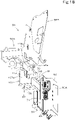
- the operator section 41 includes a communication unit 58.
- the communication unit 58 is located at or near an outer periphery of the operator section 41.
- the communication unit 58 is provided inside the cabin 5 at a front-right portion of the machine body 2 (operator section 41).
- the communication unit 58 is a unit including an information processing unit (IPU) 59, a direct communication unit (DCU) 60, and a mounting bracket 61 for attachment of the IPU 59 and the DCU 60 to a portion on the machine body 2 side.
- IPU information processing unit
- DCU direct communication unit
- mounting bracket 61 for attachment of the IPU 59 and the DCU 60 to a portion on the machine body 2 side.
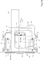
- the IPU 59 is an "information processor" which temporarily stores information relating to the working machine 1 and performs predetermined processing (for example, compression). As illustrated in FIG. 7 , the IPU 59 is connected to a communication port 62 of an in-vehicle communication network (not illustrated) via a wire harness 64, and transmits and receives information relating to the working machine 1 through the communication network.
- the in-vehicle communication network is a controller area network (CAN), FlexRay, and/or the like on the working machine 1.
- the IPU 59 is connected to the DCU 60 via the wire harness 64, and transmits data to the DCU 60.
- the DCU 60 is a "communication device" which exchanges data with external device(s) (not illustrated).
- the DCU 60 receives data from the IPU 59.
- the DCU 60 transmits, to a server, the data received from the IPU 59 and data such as position information.
- the server is, for example, a server located at a manufacturer of the working machine 1, a server located at a dealer which sells the working machine 1 and provides maintenance services for the working machine 1, and/or the like.
- the IPU 59 and the DCU 60 are connected to a power supply port 63 via the wire harness 64, and are supplied with power from the power supply port 63.
- the communication port 62 and the power supply port 63 are located in the operator section 41.
- the DCU 60 is located at or near the outer periphery of the operator section 41 such that an obverse surface 60A thereof faces outward from the machine body 2 (faces in an outward direction from the machine body).
- the DCU 60 is positioned such that the obverse surface 60A thereof faces forward.
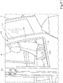
- the DCU 60 and the IPU 59 are located forward of the console 44R. Specifically, the DCU 60 and the IPU 59 are located diagonally forward and downward of the meter 51 and the air duct 57. Since the DCU 60 and the IPU 59 are located diagonally forward and downward of the meter 51 and the air duct 57, it is possible to eliminate or reduce the likelihood that the DCU 60 and the IPU 59 will interfere with the operator's view. As illustrated in FIGS. 6 and 8 , the DCU 60 is located inside the cabin 5 such that the obverse surface 60A thereof faces toward a glass surface of the cabin 5.
- the DCU 60 is located inside the cabin 5 such that the obverse surface 60A thereof faces toward the lower pane 39 of the front window 22.
- the DCU 60 is located inside the cabin 5 near the lower pane 39 such that the obverse surface 60A thereof faces forward and that the DCU 60 protrudes in the machine body width inward direction from the right edge of the window opening 30 of the front window 22 (see FIG. 8 ).
- the DCU 60 is substantially in the form of a rectangular parallelepiped with the obverse surface 60A thereof substantially in the form of a rectangle, and is positioned upright such that the longitudinal direction of the rectangular parallelepiped matches the up-and-down direction.
- the DCU 60 is located above the floor 42 of the operator section 41 with a space therebetween, and, as illustrated in FIG. 6 , is positioned such that the DCU 60 is inclined forward in the machine body width inward direction (leftward direction).
- the swing pedal 50 is provided on a front-right portion of the floor 42. The DCU 60 is located near the swing pedal 50. Since the DCU 60 is located above the floor 42 with a space therebetween and is diagonally positioned, the DCU 60 is prevented from interfering with the movement of the operator's foot to operate the swing pedal 50.
- the IPU 59 is located on the same side of the DCU 60 as the reverse surface of the DCU 60, i.e., located on the opposite side of the DCU 60 from the side where the obverse surface 60A is located (located rearward of the DCU 60 in the first embodiment).
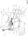
- the mounting bracket 61 includes a first bracket member 66, a second bracket member 67, and a third bracket member 68.
- the DCU 60 and the IPU 59 are attached to the first bracket member 66.
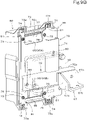
- the first bracket member 66 includes a first device mount 69 for attachment of the DCU 60 and a second device mount 78 for attachment of the IPU 59.
- the first device mount 69 is, for example, a plate member formed of a metal plate.
- the first device mount 69 is hereinafter referred to as a plate member.
- the plate member 69 is attached to the reverse surface of the DCU 60.
- the DCU 60 includes a casing 72 and a cover 73 which covers the casing 72 on the obverse surface 60A side.
- the plate member 69 includes a plurality of cover attachment portions 74.
- the plurality of cover attachment portions 74 are located at the upper left, upper right, lower left, and lower right portions of the plate member 69.
- the cover attachment portions 74 have attached thereto attachment pieces 73a at four corners of the cover 73 with bolts 75 and/or the like (see FIG. 11 ).
- the plate member 69 includes a plurality of casing attachment portions 76.
- the casing attachment portions 76 are located at the upper left, upper right, lower left, and lower right portions of the plate member 69.
- Attachment recessed portions 72a at four corners of the casing 72 are attached to the casing attachment portions 76 with bolts 79 and/or the like.
- Spacer members 77 provided in the attachment recessed portions 72a are fixed to surfaces of the respective casing attachment portions 76 of the plate member 69 that face in the same direction as the obverse surface 60A.
- the plate member 69 is attached to the attachment recessed portions 72a via the spacer members 77.
- the second device mount 78 includes a first member 70 and a second member 71.
- the first member 70 and the second member 71 are each formed of channel steel.
- the first member 70 is positioned sideways (extends in a horizontal direction) such that its open side faces the plate member 69 (faces forward), and is fixed to a lower portion of the reverse surface of the plate member 69.
- the first member 70 includes a projecting portion 70a which projects rightward from the plate member 69.
- the second member 71 is positioned upright (extends in the up-and-down direction) such that its open side faces the plate member 69 (faces forward), and is fixed to an upper right portion of the reverse surface of the plate member 69.
- the second member 71 has its lower end fixed to the first member 70.
- the IPU 59 is attached a left portion of the first member 70 and an intermediate portion of the second member 71 with fastener(s) such as bolts(s).
- the left portion of the first member 70 and the intermediate portion of the second member 71 (to which the IPU 59 is attached) constitute an attachment portion (first attachment portion) 80 for attachment of the IPU 59.
- the cover attachment portions 74 and the casing attachment portions 76 constitute an attachment portion (second attachment portion) 81 for attachment of the DCU 60. That is, the mounting bracket 61 includes the first attachment portion 80 for attachment of the IPU 59 and the second attachment portion 81 for attachment of the DCU 60.
- the second bracket member 67 includes a first wall 67a attached to the projecting portion 70a of the first member 70, a second wall 67b extending rearward from a lower end of the first wall 67a, and a third wall 67c extending upward from a left end of the second wall 67b and fixed to the first wall 67a.
- the third bracket member 68 projects rearward from the second bracket member 67, and has its rear portion located on one side (on the right side) of the front frame 56.
- the third bracket member 68 includes a main member 68A, a rest member 68B, and a reinforcing member 82.
- the main member 68A includes a bottom wall portion 68a, a first side wall portion 68b, a second side wall portion 68c, and an upward-extending wall 68d.
- the bottom wall portion 68a has its front portion fixed to the second wall 67b of the second bracket member 67 with bolt(s).
- the bottom wall portion 68a projects rearward from the second wall 67b.
- the bottom wall portion 68a is attached to a cover member 86A of a support bracket 86 (described later) with bolt(s) 87.
- the first side wall portion 68b extends upward from a left edge of a rear portion of the bottom wall portion 68a.
- the first side wall portion 68b is fixed to attachment portion(s) 83 of the main frame 56A of the front frame 56 with bolt(s) 84 (see FIG. 6 ).
- the second side wall portion 68c extends upward from a right edge of the bottom wall portion 68a.
- the upward-extending wall 68d extends upward from an intermediate portion of the left edge of the bottom wall portion 68a in the front-rear direction K1.
- the rest member 68B is formed of a plate member, is fixed to a lower surface of the bottom wall portion 68a, and is placed on the cover member 86A.
- the reinforcing member 82 includes a first reinforcing plate 82A, a second reinforcing plate 82B, and a third reinforcing plate 82C.
- the first reinforcing plate 82A extends in the front-rear direction K1 from a front portion to an intermediate portion of the bottom wall portion 68a in the front-rear direction K1 and also extends upward from an upper surface of the bottom wall portion 68a.
- the second reinforcing plate 82B is fixed to a rear end of the first reinforcing plate 82A and bridges the gap between the upward-extending wall 68d and the second side wall portion 68c.
- the third reinforcing plate 82C connects the first side wall portion 68b and the second side wall portion 68c.
- the support bracket 86 to support a controller 85 (for example, an engine electric control unit (engine ECU) to control the prime mover) of the working machine 1 is located below the bottom wall portion 68a.
- the support bracket 86 is located on the opposite side of the console 44R from the operator's seat 6. In the present embodiment, the support bracket 86 is located rightward of the console 44R.
- the support bracket 86 includes the cover member 86A which covers the controller 85 and which is for attachment of the controller 85, a stay member 86B fixed to the cover member 86A, a support member 86C to support the stay member 86B, and a base member 86D fixed to a lower end of the support member 86C.
- the cover member 86A has, fixed thereto with bolt(s), a rear portion of the bottom wall portion 68a (see FIG. 4 ).
- the stay member 86B is fixed to an attachment portion 88 of the main frame 56A of the front frame 56 with bolt(s).
- the base member 86D is attached to the machine body 2. That is, the support bracket 86 is attached to the machine body 2.
- the first side wall portion 68b constitutes an attachment portion (third attachment portion) 89 for attachment of the mounting bracket 61 to the console 44R.
- the rear portion of the bottom wall portion 68a constitutes an attachment portion (fourth attachment portion) 90 for attachment of the mounting bracket 61 to the support bracket 86. That is, the mounting bracket 61 includes the third attachment portion 89 attached to the console 44R and the fourth attachment portion 90 attached to the support bracket 86. In other words, the mounting bracket 61 is attached to a portion on the machine body 2 side.
- the mounting bracket 61 is configured to be attached to the console 44R and the support bracket 86, and therefore the communication unit 58 (a unit including the DCU 60, the IPU 59, and the mounting bracket 61) can be attached as an add-on to the working machine 1 including the console 44R and the support bracket 86. Furthermore, because it is possible to mount, on the machine body 2, the communication unit 58 which is an assembly of the DCU 60 and the IPU 59 attached on the mounting bracket 61, it is possible to easily do the work of attaching the communication unit 58 (the DCU 60 and the IPU 59).
- the DCU 60 and the IPU 59 are provided on the machine body 2 such that the IPU 59 is located on the same side of the DCU 60 as the reverse surface of the DCU 60, making it possible to arrange the DCU 60 and the IPU 59 in a compact manner.
- the following description discusses a structure of the DCU 60 and a waterproof structure in detail.
- the DCU 60 includes an electronic substrate 91 housed in the casing 72.
- the casing 72 is substantially in the form of a rectangular parallelepiped, and is divided in two parts one of which is on the obverse surface 60A side and the other of which is on the DCU's reverse surface side.
- the electronic substrate 91 has one or more communication antennas (3G antennas) 92 and a positioning antenna (GPS antenna) 93 on its obverse surface for attachment of electronic components.
- the electronic substrate 91 is housed in the casing 72 such that its obverse surface and the obverse surface 60A of the DCU 60 face in the same direction.
- the communication antennas 92 communicate with a server, and are located on an upper portion and a lower portion of the electronic substrate 91.
- the communication antennas 92 are contained in the DCU 60.
- the communication antennas 92 were attached to the working machine 1 separately from the main body of the DCU 60, disconnection of the harness connecting the main body of the DCU 60 and the communication antennas 92 would prevent a notification from being sent to an external device (such as a server) in case of theft of the DCU 60.
- an external device such as a server
- the communication antennas 92 contained in the DCU 60 it is possible to keep communication possible even during unlawful acts such as stealing of the DCU 60 (such as the act of detaching the DCU 60), and thus possible to send a notification to a certain recipient.
- the positioning antenna 93 receives one or more satellite signals from one or more positioning satellites.
- the positioning antenna 93 is located on a lower right portion of the electronic substrate 91.
- the working machine 1 detects the position thereof (measured position information including latitude and longitude) based on the satellite signals received by the positioning antenna 93 using a positioning system.
- the working machine 1 uses a well-known Global Positioning System (GPS) which is an example of Global Navigation Satellite Systems (GNSS) (for example, uses RTK-GPS suitable for positioning mobile objects) to determine the position and heading of the working machine 1.
- GPS Global Positioning System
- GNSS Global Navigation Satellite Systems
- the working machine 1 communicates with a base station (reference station) located at a known position, and the base station transmits, to the working machine 1, positioning data (correction information) obtained by receiving radio waves from the positioning satellites.
- the working machine 1 detects the position thereof (latitude, longitude) based on positioning data obtained by receiving radio waves from the positioning satellites and the positioning data received from the base station.
- the DCU 60 receives and transmits position information.
- a connector 94 for connection of the wire harness 64 is provided on an upper right portion of the DCU 60.
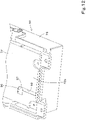
- the cover 73 is made of resin, and includes an obverse wall 73b covering the obverse surface 60A side of the casing 72, an upper wall 73c covering an upper surface of the casing 72, a lower wall 73d covering a lower surface of the casing 72, a first side wall 73e covering a side surface (left surface) of the casing 72, and a second side wall 73f covering the opposite side surface (right surface) of the casing 72.
- the cover 73 covers the opposite surface of the casing 72 from the surface facing the plate member 69.
- the plate member 69 covers a reverse surface (one surface) 72b of the casing 72 defining the reverse side of the DCU 60.
- the cover 73 and the plate member 69 together house the casing 72.
- the plate member 69 has cutouts 95 obtained by cutting portions corresponding to the communication antennas 92.
- the plate member 69 has a cutout 95A corresponding to a communication antenna 92A in an upper portion thereof and has a cutout 95B corresponding to a communication antenna 92B in a lower portion thereof.
- the communication antennas 92 have higher sensitivity in the thickness direction of the electronic substrate 91.
- the cover 73 is made of resin and the plate member 69 has cutouts in portions corresponding to the communication antennas 92, making it possible to avoid interference with the radio wave directivity of the communication antennas 92.
- the IPU 59 is located on the opposite surface of the plate member 69 from the surface facing the reverse surface 72b of the casing 72 such that the IPU 59 is out of alignment with the cutouts 95. That is, the IPU 59 is located on the same side of the DCU 60 as the reverse surface of the DCU 60 such that the DCU 60 is out of alignment with the communication antennas 92. This prevents the interference of the IPU 59 with the radio wave directivity of the communication antennas 92.
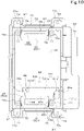
- the reverse surface 72b of the casing 72 defining the reverse side of the DCU 60 has a hole 96 for air escape (air hole) to eliminate the pressure difference between the outside and the inside of the casing 72.
- the air hole 96 is in a lower left portion of the reverse surface 72b of the casing 72 that is the surface in which the air hole 96 is formed.
- a coating sheet 97 to close the air hole 96 from the inside of the casing 72 is attached to the portion of the casing 72 that has the air hole 96.
- the coating sheet 97 has the property of allowing passage of air but preventing passage of water. The coating sheet 97 prevents water ingress into the casing 72 via the air hole 96.
- the plate member 69 faces the reverse surface 72b of the casing 72 having the air hole 96, and covers the air hole 96.
- the plate member 69 is capable of preventing car washing water or the like from directly hitting the air hole 96 from behind (from a direction normal to the reverse surface 72b of the casing 72).
- the reverse surface 72b of the casing 72 has a groove 98 extending downward from the air hole 96.
- One of opposite end portions of the groove 98 in a longitudinal direction (upper end) is in communication with the air hole 96, and the other of the opposite end portions of the groove 98 in the longitudinal direction (lower end) has an opening facing downward.
- the communication unit 58 includes a sealing member 99 interposed between the plate member 69 and the reverse surface 72b of the casing 72.
- the sealing member 99 is a member to seal up the air hole 96, and is interposed between the plate member 69 and the reverse surface 72b of the casing 72 to prevent water ingress into the casing 72 through the air hole 96.
- the sealing member 99 includes an adhesive sheet 99A to bond the sealing member 99 to the plate member 69, and a sealing body 99B which abuts on the reverse surface 72b of the casing 72.
- the sealing body 99B is made of an elastic material such as expanded rubber with closed cells.
- the sealing member 99 is in the form of a plate in contact with the plate member 69 and the reverse surface 72b of the casing 72. This makes it possible to place the sealing member 99 in a narrow space between the plate member 69 and the reverse surface 72b of the casing 72, and possible to improve reliability (stability) of sealing.
- the plate member 69 abuts on an abutment surface 100 of the cover 73 and on the spacer members 77 such that a certain gap forms between the plate member 69 and the reverse surface 72b of the casing 72. With this, the plate member 69, when attached to the DCU 60, squeezes the sealing member 99 (sealing body 99B) to an appropriate extent.
- portions of the surface of the plate member 69 and the reverse surface 72b of the casing 72 that abut on the sealing member 99 may be flat or have an uneven profile.
- the shape of the sealing member 99 need only be a shape that achieves waterproofness when the sealing member 99 is interposed between the plate member 69 and the reverse surface 72b of the casing 72.
- the surface(s) of the sealing member 99 that abut(s) on the plate member 69 and/or the reverse surface 72b of the casing 72 may be flat or have an uneven profile conforming to that of the plate member 69 and/or the reverse surface 72b of the casing 72.
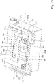
- the sealing member 99 has a groove portion 101 passing through the sealing member 99 in the thickness direction.
- One of the opposite ends of the groove portion 101 in the longitudinal direction is closed, and the other of the opposite ends of the groove portion 101 is open.
- the groove portion 101 includes a closed portion 101a at the one of the opposite ends, and an open portion 101b at the other of the opposite ends.
- the open portion 101b has an opening facing downward.
- the groove portion 101 includes a horizontal groove portion 101c and a vertical groove portion 101d.
- the horizontal groove portion 101c includes the closed portion 101a at one end thereof, this end is in communication with the air hole 96, and the horizontal groove portion 101c extends horizontally (in a horizontal direction) from the air hole 96.
- the vertical groove portion 101d extends downward from the opposite end of the horizontal groove portion 101c.
- the vertical groove portion 101d includes the open portion 101b at the lower end thereof.
- the groove portion 101 allows escape of droplets (drainage of water) resulting from condensation and/or water that has entered the air hole 96 for some reasons.
- the groove portion 101 also allows the air hole 96 to communicate with the outside environment, making it possible to achieve air exchange through the air hole 96.
- the sealing member 99 includes a first section 99a, a second section 99b, a third section 99c, a fourth section 99d, and a fifth section 99e.
- the first section 99a is located lower than the air hole 96.
- the second section 99b is located higher than the air hole 96.
- the first section 99a and the second section 99b each extend horizontally (rightward) from the air hole 96.
- the third section 99c is located on one of the opposite sides (left side) of the air hole 96 in the horizontal direction, and connects the first section 99a and the second section 99b.
- the fourth section 99d extends downward from the end (right end) of the first section 99a on the other of the opposite sides of the air hole 96 in the horizontal direction.
- the fifth section 99e extends downward from the end (right end) of the second section 99b on the other of the opposite sides of the air hole 96 in the horizontal direction. Lower ends of the fourth section 99d and the fifth section 99e are not connected together.
- the gap between the first section 99a and the second section 99b is the horizontal groove portion 101c. That is, the horizontal groove portion 101c is defined by the first section 99a, the second section 99b, and the third section 99c.
- the gap between the fourth section 99d and the fifth section 99e is the vertical groove portion 101d. That is, the vertical groove portion 101d is defined by the fourth section 99d and the fifth section 99e.
- the first section 99a extends from one of opposite ends of the cutout 95B to the other of the opposite ends of the cutout 95B, and lies between the air hole 96 and the cutout 95B. That is, the sealing member 99 includes a section lying between the air hole 96 and the cutout 95B.
- the first section 99a prevents water ingress into the air hole 96 via the cutout 95. That is, even when the air hole 96 is present near the cutout 95B (communication antenna 92), it is possible to appropriately prevent water ingress into the air hole 96.
- the second section 99b prevents water ingress into the air hole 96 from above.
- the third section 99c prevents water ingress into the air hole 96 from the left.
- the fourth section 99d prevents water ingress into the air hole 96 from the right.
- the working machine 1 in which the DCU 60 and the IPU 59 are provided inside the cabin 5 provided on the machine body 2 is discussed as an example. Note, however, that the working machine 1 may be a working machine 1 in which a canopy instead of the cabin 5 is provided on the machine body 2. Alternatively, the working machine 1 may be a working machine 1 with no cabin 5 or canopy.
- the second embodiment shows an example in which a working machine 1, including a machine body having a four-pillar canopy 106 thereon, includes the communication unit 58. Also in the working machine of the second embodiment, the communication unit 58 is located in a front-right portion of the operator section 41.
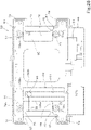
- the DCU 60 and the IPU 59 are located diagonally forward and downward of the console 44R (meter 51) similarly to the first embodiment, but the DCU 60 is located with the obverse surface 60A thereof facing in a machine body width outward direction (rightward) and, as illustrated in FIG. 16 , the IPU 59 is located on the left side of the DCU 60, i.e., located on the same side of the DCU 60 as the reverse surface of the DCU 60.
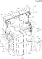
- the mounting bracket includes a first bracket member 66 for attachment of the DCU 60 and the IPU 59 and a second bracket member 67 for attachment to the console 44R.
- the first bracket member 66 includes a first device mount (plate member) 69 and a second device mount 78.
- the plate member 69 has the DCU 60 attached thereto.
- the second device mount 78 has the IPU 59 attached thereto.
- the second device mount 78 includes a first member 70 and a second member 71.
- the first member 70 and the second member 71 are each formed of channel steel.
- the first member 70 extends in the front-rear direction K1 such that its open side faces the plate member 69 (faces rightward), and is fixed to an upper portion of the left surface of the plate member 69.
- the first member 70 includes a projecting portion 70a which is a rear portion thereof, and the projecting portion 70a projects rearward from the plate member 69.
- the second member 71 is positioned upright such that its open side faces the plate member 69 (faces rightward).
- the second member 71 is located below the first member 70 and fixed to a rear portion of the plate member 69.
- the IPU 59 is attached to a front portion of the first member 70 and a lower portion of the second member 71 with fastener(s) such as bolt(s).
- the front portion of the first member 70 and the lower portion of the second member 71 constitute a first attachment portion 80 for attachment of the IPU 59.
- the second bracket member 67 includes an attachment member 107, a lower plate member 108, a reinforcing plate 109, and a connecting plate 110.
- the attachment member 107 includes a front wall 107a, a rear wall 107b located rearward of the front wall 107a with a space therebetween, and a side wall 107c which connects left edges of the front wall 107a and the rear wall 107b.
- the front wall 107a and the rear wall 107b are fixed to the left surface of the projecting portion 70a of the first member 70.
- the lower plate member 108 is fixed to a lower surface of the attachment member 107 and connects the front wall 107a and the rear wall 107b.
- the lower plate member 108 is also fixed to the left surface of the projecting portion 70a of the first member 70.
- the reinforcing plate 109 connects the front wall 107a and the projecting portion 70a.
- the connecting plate 110 connects together an intermediate portion of the front wall 107a in the up-and-down direction and an intermediate portion of the rear wall 107b in the up-and-down direction.
- the front frame 56 includes an attachment stay 111.
- the attachment stay 111 includes a first stay plate 112 and a second stay plate 113.
- the first stay plate 112 includes an upper wall 112a fixed to a base plate 56a of the front frame 56 and an extension wall 112b which extends downward from a left edge of the upper wall 112a.
- the second stay plate 113 has an upper portion 113a fixed to a left surface of the extension wall 112b of the first stay plate 112 and has a lower portion 113b located on a right surface of the side wall 107c of the attachment member 107.
- the side wall 107c of the attachment member 107 is attached to the lower portion 113b of the second stay plate 113 with fastener(s) 114 including bolt(s) and nut(s).
- a reinforcing plate 115 is fixed to a right surface of the second stay plate 113.
- the reinforcing plate 115 has an upper edge thereof fixed to a lower edge of the first stay plate 112.
- the side wall 107c of the second bracket member 67 constitutes a third attachment portion 89 for attachment of the mounting bracket 61 to the console 44R.
- the arrangement of the communication unit 58 (DCU 60, IPU 59) in the second embodiment may be applied to a working machine 1 with a cabin.
- glass is provided rightward of the DCU 60, and the DCU 60 is positioned such that the DCU 60 faces toward the glass.
- the communication unit 58 is located diagonally leftward and rearward of the operator's seat 6 inside the cabin 5 near the inner surface of the side window 24.
- the DCU 60 is located higher than a lower edge of the window frame 31 of the side window 24.
- the DCU 60 is positioned such that the obverse surface 60A thereof faces leftward (faces in the machine body outward direction).
- the DCU 60 is positioned such that the obverse surface 60A thereof faces toward the side glass 33.
- the DCU 60 is positioned sideways with the connector 94 pointing downward such that the longitudinal direction of its rectangular parallelepiped matches a horizontal direction (in the example in FIG.
- the communication antennas 92 are located at front and rear portions of the DCU 60.
- the positioning antenna 93 is located at a lower rear portion of the DCU 60.
- the air hole 96 is located at an upper rear portion of the DCU 60.
- the sealing member 99 is in the form of a rectangle elongated in the up-and-down direction.
- the groove portion 101 extends in the up-and-down direction, and is in the form of a vertically elongated groove including opposite ends in the longitudinal direction one of which is a closed upper end and the other of which is an open lower end.
- the groove portion 101 includes the upper end in communication with the air hole 96, extends downward from the air hole 96, and includes the open portion 101b at the lower end.
- the groove portion 101 is defined by a first portion 102a, a second portion 102b, and a third portion 102c of the sealing member 99.
- the first portion 102a is located on one of opposite sides of the air hole 96 in a horizontal direction (located rearward of the air hole 96).
- the second portion 102b is located on the other of the opposite sides of the air hole 96 in the horizontal direction (located forward of the air hole 96).
- the third portion 102c is located higher than the air hole 96 and connects the first portion 102a and the second portion 102b.
- the first section 102a lies between the air hole 96 and the cutout 95B.
- the mounting bracket 61 for attachment of the DCU 60 and the IPU 59 includes a first bracket member 66 and a second bracket member 67.
- the first bracket member 66 includes a first device mount (plate member) 69 for attachment of the DCU 60, a second device mount 78 for attachment of the IPU 59, and a bracket attachment member 116.
- the second device mount 78 includes a first member 70 and a second member 71 which are each formed of channel steel and fixed to a right surface of the plate member 69.
- the first member 70 extends in the up-and-down direction with its open side facing the plate member 69 (facing leftward), and is fixed to an intermediate portion of the plate member 69 in the front-rear direction K1.
- the second member 71 extends in the front-rear direction K1 with its open side facing the plate member 69 (facing leftward). The second member 71 is located forward of the first member 70 and is fixed to a lower portion of the plate member 69.
- the IPU 59 is fixed to a lower portion of the first member 70 and a front portion of the second member 71 with bolts.
- the lower portion of the first member 70 and the front portion of the second member 71 constitute a first attachment portion 80 for attachment of the IPU 59.
- the bracket attachment member 116 is formed of channel steel, has its open side facing the plate member 69 (facing leftward), and extends in the front-rear direction K1.
- the bracket attachment member 116 is located rearward of the first member 70 and is fixed to a lower portion of the plate member 69.
- the bracket attachment member 116 has its rear portion projecting rearward from the plate member 69.
- the rear portion of the bracket attachment member 116 is attached to a tank stay 117.
- the bracket attachment member 116 is welded to the tank stay 117 in the present embodiment, the bracket attachment member 116 may be fixed to the tank stay 117 with bolt(s).
- the tank stay 117 supports a window washer tank (tank) 118 for storage of window washing liquid.
- the window washer tank 118 is located inside the cabin 5.
- the window washer tank (tank) 118 is located rearward of the DCU 60.
- the tank stay 117 includes an attachment stay 119, a support stay 120, and a reinforcing plate 121.
- the attachment stay 119 includes a main wall 119a and a bent wall 119b which extends forward from an upper edge of the main wall 119a.
- the main wall 119a is attached to a wall portion (first wall portion) 122 at the rear of the cabin 5 with bolt(s) (see FIG. 23 ).
- the attachment stay 119 has, fixed to a front surface of its left portion, a rear portion of the bracket attachment member 116.
- the support stay 120 is fixed to a front surface of a right portion of the attachment stay 119.
- the reinforcing plate 121 is fixed to a front surface of the main wall 119a and is fixed to the bracket attachment member 116 and the attachment stay 119.
- the window washer tank 118 includes an attachment part 123 fixed to a rear surface of the tank.
- the attachment part 123 is fixed to the support stay 120 with bolt(s).
- the second bracket member 67 is located on the opposite side of the first bracket member 66 from the tank stay. Specifically, the second bracket member 67 is located forward of the IPU 59.
- the second bracket member 67 has one of its opposite ends attached to the first bracket member 66 and has the other of the opposite ends attached to a wall portion (second wall portion) 124 of the cabin 5.
- the second wall portion 124 is located rearward of a lower portion of the entrance/exit door 23 of the cabin 5.
- the second wall portion 124 is, for example, a door lock cover which covers a door locking mechanism to lock the entrance/exit door 23.
- the second bracket member 67 is described in detail. As illustrated in FIGS. 23 , 26 , 27 , and 28 , the second bracket member 67 includes a first element 126 and a second element 127.
- the first element 126 is formed of a rod, and has an upper portion 126a thereof fixed to a front portion of the second member 71 with bolt(s).
- the first element 126 includes the upper portion 126a extending downward from a front portion of the second member 71, an intermediate portion 126b inclined forward in the downward direction from the upper portion 126a, and a lower portion 126c extending downward from the intermediate portion 126b.
- the second element 127 is fixed to the lower portion 126c of the first element 126.
- the second element 127 is attached to the second wall portion 124 with bolt(s).
- one end of the mounting bracket 61 is attached to the tank stay 117 and the opposite end of the mounting bracket 61 is attached to the second wall portion 124, making it possible to attach the communication unit 58 (a unit including the DCU 60, the IPU 59, and the mounting bracket 61) as an add-on to the working machine 1. Furthermore, since the one end of the mounting bracket 61 is supported on the tank stay 117 (first wall portion 122) and the opposite end of the mounting bracket 61 is supported on the second wall portion 124, the mounting bracket 61 is supported at opposite ends thereof and capable of firmly supporting the DCU 60 and the IPU 59. Even when the mounting bracket 61 is attached to the tank stay 117, the tank stay 117 is capable of firmly supporting the window washer tank 118.
- the location (arrangement) of the communication unit 58 is not limited to those described in the foregoing embodiments.
- the DCU 60 may be located rearward of the backrest 6B of the operator's seat 6 such that the obverse surface 60A thereof faces rearward.
- the DCU 60 is located inside the cabin 5 such that the obverse surface 60A thereof faces a glass (rear glass) which closes the window opening of the rear window.
- the DCU 60 may be located rearward of the operator's seat 6 such that the obverse surface 60A thereof faces diagonally rearward.
- the mounting bracket 61 may be attached to a connecting rod which connects a left rear pillar and a right rear pillar, a handrail located on one side of the operator's seat, and/or the like.
- the mounting bracket 61 may be attached to a support frame which is attached to the machine body such that the support frame straddles the prime mover (engine) on a rear portion of the machine body 2.
- the mounting bracket 61 is attached to member(s) (the console 44R, the support bracket 86, and/or the cabin 5) provided on the machine body 2 in the foregoing embodiments, the mounting bracket 61 may be attached directly to the machine body 2.
- a communication unit 58 as described above includes an information processor (IPU 59), a communication device (DCU 60) to receive data from the information processor 59, the communication device (DCU 60) including a communication antenna 92 to transmit data, and a mounting bracket 61 for attachment of the communication device 60 and the information processor 59 to an object (machine body 2), wherein the communication device 60 and the information processor 59 are attached to the mounting bracket 61 such that the information processor 59 is located on the same side of the communication device 60 as a reverse surface of the communication device 60 and is out of alignment with the communication antenna 92.
- IPU 59 information processor
- DCU 60 communication device to receive data from the information processor 59
- the communication device (DCU 60) including a communication antenna 92 to transmit data
- a mounting bracket 61 for attachment of the communication device 60 and the information processor 59 to an object (machine body 2), wherein the communication device 60 and the information processor 59 are attached to the mounting bracket 61 such that the information processor 59 is located on the same side of the
- the communication device 60 containing the communication antenna(s) 92 and the information processor 59 can be attached to the mounting bracket 61 to form a single unit and then mounted on an object (machine body 2).
- the communication device 60 and the information processor 59 can therefore be attached in a suitable manner.
- the information processor 59 is attached to the mounting bracket 61 such that the information processor 59 is located on the same side of the communication device 60 as the reverse surface thereof, the communication device 60 and the information processor 59 can be arranged in a compact manner.
- the information processor 59 is attached to the mounting bracket 61 such that the information processor 59 is located on the same side of the communication device 60 as the reverse surface thereof and that the information processor 59 is out of alignment with the communication antenna(s) 92, it is possible to eliminate or reduce the likelihood that the information processor 59 interferes with the directivity performance of the communication antenna(s) 92 contained in the communication device 60.
- the mounting bracket 61 includes a plate member 69 attached to the reverse surface of the communication device 60.
- the plate member 69 has a cutout 95 formed by cutting a portion corresponding to the communication antenna 92.
- the information processor 59 is located on an opposite surface of the plate member 69 from a surface facing the reverse surface of the communication device 60 and is out of alignment with the cutout 95.
- the configuration makes it possible to ensure the communication performance of the communication device 60 containing communication antenna(s) 92.
- the communication device 60 includes an electronic substrate 91 including an obverse surface to which the communication antenna 92 is attached, a casing 72 housing the electronic substrate 91 such that the obverse surface of the electronic substrate 91 and an obverse surface of the communication device 60 face in the same direction, and a positioning antenna 93 to receive one or more satellite signals from one or more positioning satellites, the positioning antenna 93 being attached to the obverse surface of the electronic substrate 91.
- the configuration makes it possible to ensure the communication performance of the communication device 60.
- a working machine 1 includes a machine body 2 to which the communication unit 58 is attached, wherein the communication device 60 is positioned with an obverse surface thereof facing outward from the machine body.
- the configuration makes it possible to ensure the communication performance of the communication device 60 containing communication antenna(s) 92.
- the working machine 1 further includes a cabin 5 provided on the machine body 2 and including a glass surface (surface of a front glass 32, side glass 33, or the like).
- the communication device 60 is located inside the cabin 5 such that the obverse surface 60A of the communication device 60 faces toward the glass.
- the configuration makes it possible to ensure the communication performance of the communication device 60 containing communication antenna(s) 92.
- the working machine 1 further includes an operator's seat 6, and a console 44R located on one side of the operator's seat 6.
- the communication device 60 is located forward of the console 44R.
- the mounting bracket 61 is attached to the console 44R.
- the configuration makes it possible to eliminate or reduce the likelihood that the communication device 60 and the information processor 59 interfere with the operator's view.
- the console 44R includes a meter 51 at a front portion thereof.
- the communication device 60 is located diagonally forward and downward of the meter 51.
- the configuration makes it possible to eliminate or reduce the likelihood that the communication device 60 and the information processor 59 interfere with the operator's view.
- the working machine 1 further includes a support bracket 86 located on an opposite side of the console 44R from the operator's seat 6 and supporting a controller 85 of the working machine 1.
- the mounting bracket 61 is attached to the support bracket 86.
- the console 44R and the support bracket 86 can be used to achieve stable attachment of the mounting bracket 61.
- the working machine 1 further includes a tank 118 located inside the cabin 5, and a tank stay 117 supporting the tank 118.
- the mounting bracket 61 includes a first bracket member 66 to which the information processor 59 and the communication device 60 are attached and which is attached to the tank stay 117, and a second bracket member 67 located on an opposite side of the first bracket member 66 from the tank stay, having one of opposite ends attached to the first bracket member 66, and having the other of the opposite ends attached to a wall portion 124 of the cabin 5.
- the communication device 60, the information processor 59, and the tank 118 are supported at opposite ends by the tank stay 117 and the second bracket member 67. This makes it possible to firmly support the communication device 60 and the information processor 59 and firmly support the tank 118.
- the communication device 60 includes an electronic substrate 91 including an obverse surface to which the communication antenna 92 is attached, a casing 72 housing the electronic substrate 91 such that the obverse surface of the electronic substrate 91 and an obverse surface 60A of the communication device 60 face in the same direction, and a positioning antenna 93 to receive one or more satellite signals from one or more positioning satellites, the positioning antenna 93 being attached to the obverse surface of the electronic substrate 91.
- the configuration makes it possible to ensure the communication performance of the communication device 60.
- a waterproof structure for a communication device 60 as described above is a waterproof structure for a communication device (DCU 60), the communication device (DCU 60) including a casing 72 that houses an electronic substrate 91 and has an air hole 96, the waterproof structure including a plate member 69 facing the casing 72 and attached to the casing 72 such that the plate member 69 covers the air hole 96, and a sealing member 99 interposed between the plate member 69 and the casing 72 to prevent ingress of water into the air hole 96 through a gap between the plate member 69 and the casing 72.
- the plate member 69 and the sealing member 99 prevent water ingress into the casing 72 through the air hole 96.
- the sealing member 99 is in the form of a plate.
- the sealing member 99 can be interposed in a compact manner between the plate member 69 and the casing 72, and sealing stability can be improved.
- the sealing member 99 includes a groove portion 101, one of opposite ends of the groove portion 101 in a longitudinal direction being in communication with the air hole 96.
- the groove portion 101 includes, at the other of the opposite ends thereof in the longitudinal direction, an open portion 101b with an opening facing downward.
- the configuration allows water to escape through the air hole 96.
- the groove portion 101 includes a horizontal groove portion 101c including opposite ends one of which is in communication with the air hole 96 and extending in a horizontal direction from the air hole 96, and a vertical groove portion 101d extending downward from the other of the opposite ends of the horizontal groove portion 101c and including the open portion 101b at a lower end thereof.
- the configuration makes it possible to prevent or reduce the ingress of water into the air hole 96 through the groove portion 101.
- the sealing member 99 includes a first section 99a located lower than the air hole 96, a second section 99b located higher than the air hole 96, a third section 99c located on one of opposite sides of the air hole 96 in the horizontal direction and connecting the first section 99a and the second section 99b, a fourth section 99d extending downward from an end of the first section 99a on the other of the opposite sides of the air hole 96 in the horizontal direction, and a fifth section 99e extending downward from an end of the second section 99b on the other of the opposite sides of the air hole 96 in the horizontal direction.
- the horizontal groove portion 101c is defined by the first section 99a, the second section 99b, and the third section 99c.
- the vertical groove portion 101d is defined by the fourth section 99d and the fifth section 99e.
- the configuration makes it possible to achieve a simple configuration of the sealing member 99.
- the groove portion 101 is a groove elongated vertically, the groove portion 101 including an upper end portion in communication with the air hole 96, extending downward from the air hole 96, and including the open portion 101b at a lower end thereof.
- the configuration makes it possible to prevent or reduce the ingress of water into the air hole 96 through the groove portion 101.
- the sealing member 99 includes a first portion 102a located on one of opposite sides of the air hole 96 in a horizontal direction, a second portion 102b located on the other of the opposite sides of the air hole 96 in the horizontal direction, and a third portion 102c located higher than the air hole 96 and connecting the first portion 102a and the second portion 102b.
- the groove portion 101 is defined by the first portion 102a, the second portion 102b, and the third portion 102c.
- the configuration makes it possible to achieve a simple configuration of the sealing member 99.
- the communication device 60 includes a communication antenna 92B contained in the casing 72 in the vicinity of the air hole 96.
- the plate member 69 has a cutout 95B in a portion corresponding to the communication antenna 92B.
- the sealing member 99 includes a section (first section 99a, first portion 102a) lying between the air hole 96 and the cutout 95B.
- the section lying between the air hole 96 and the cutout 95B makes it possible to appropriately prevent water ingress into the air hole 96.
- the waterproof structure further includes a cover 73 to cover an opposite surface of the casing 72 from a surface facing the plate member 69, the casing 72 being housed in a space defined by the plate member 69 and the cover 73.
- the plate member 69 and the cover 73 appropriately prevent water ingress into the casing 72.
Landscapes
- Engineering & Computer Science (AREA)
- Mining & Mineral Resources (AREA)
- Civil Engineering (AREA)
- General Engineering & Computer Science (AREA)
- Structural Engineering (AREA)
- Computer Networks & Wireless Communication (AREA)
- Signal Processing (AREA)
- Microelectronics & Electronic Packaging (AREA)
- Mechanical Engineering (AREA)
- Fittings On The Vehicle Exterior For Carrying Loads, And Devices For Holding Or Mounting Articles (AREA)
Abstract
Description
- The present invention relates to a waterproof structure for a communication device, a communication unit, and a working machine.
-
Patent Literature 1 discloses a working machine equipped with a communication network system. - The communication network system disclosed in
Patent Literature 1 includes a communication device (wireless terminal for a working machine) provided on a working machine. The communication device transmits information relating to the working machine to an information collection terminal. - The working machine disclosed in
Patent Literature 1 includes an information processor (first controller) which receives and processes information relating to the working machine, and a communication device (wireless terminal for a working machine) which receives data from the information processor. The communication device transmits information relating to the working machine to an information collection terminal. - [Patent Literature 1]
Japanese Unexamined Patent Application Publication No. 2013-16118 - In some communication devices, a casing which houses an electronic substrate has a hole for air escape (air hole) to prevent the occurrence of the pressure difference between the outside and the inside of the casing. The air hole in the casing may lead to water ingress through the air hole, depending on the place where the communication device is. In view of this, the communication device needs to be waterproofed to prevent water ingress through the air hole.
- Furthermore, with regard to the working machine, the communication device and the information processor need to be capable of being attached to the machine body in a suitable manner and arranged in a suitable manner.
- An object of the present invention is to provide a waterproof structure to prevent water ingress through an air hole in a casing of a communication device.
- Another object of the present invention is to provide a communication unit and a working machine in each of which a communication device and an information processor can be attached and arranged in a suitable manner.
- A waterproof structure for a communication device according to an aspect of the present invention is a waterproof structure for a communication device including a casing that houses an electronic substrate and has an air hole, the waterproof structure including a plate member facing the casing and attached to the casing such that the plate member covers the air hole, and a sealing member interposed between the plate member and the casing to prevent ingress of water into the air hole through a gap between the plate member and the casing.
- The sealing member is in the form of a plate.
- The sealing member includes a groove portion, one of opposite ends of the groove portion in a longitudinal direction being in communication with the air hole. The groove portion includes, at the other of the opposite ends thereof in the longitudinal direction, an open portion with an opening facing downward.
- The groove portion includes a horizontal groove portion including opposite ends one of which is in communication with the air hole and extending in a horizontal direction from the air hole, and a vertical groove portion extending downward from the other of the opposite ends of the horizontal groove portion and including the open portion at a lower end thereof.
- The sealing member includes a first section located lower than the air hole, a second section located higher than the air hole, a third section located on one of opposite sides of the air hole in the horizontal direction and connecting the first section and the second section, a fourth section extending downward from an end of the first section on the other of the opposite sides of the air hole in the horizontal direction, and a fifth section extending downward from an end of the second section on the other of the opposite sides of the air hole in the horizontal direction. The horizontal groove portion is defined by the first section, the second section, and the third section. The vertical groove portion is defined by the fourth section and the fifth section.
- The groove portion is a groove elongated vertically, the groove portion including an upper end portion in communication with the air hole, extending downward from the air hole, and including the open portion at a lower end thereof.
- The sealing member includes a first portion located on one of opposite sides of the air hole in a horizontal direction, a second portion located on the other of the opposite sides of the air hole in the horizontal direction, and a third portion located higher than the air hole and connecting the first portion and the second portion. The groove portion is defined by the first portion, the second portion, and the third portion.
- The communication device includes a communication antenna contained in the casing in the vicinity of the air hole. The plate member has a cutout in a portion corresponding to the communication antenna. The sealing member includes a section lying between the air hole and the cutout.
- The waterproof structure further includes a cover to cover an opposite surface of the casing from a surface facing the plate member, the casing being housed in a space defined by the plate member and the cover.
- The communication device receives data from an information processor and includes a communication antenna to transmit data. The communication device and the information processor are attached to a mounting bracket such that the information processor is located on the same side of the communication device as a reverse surface of the communication device and is out of alignment with the communication antenna, the mounting bracket being a bracket for attachment of the communication device and the information processor to an object.
- A communication unit according to an aspect of the present invention includes an information processor, a communication device to receive data from the information processor, the communication device including a communication antenna to transmit data, and a mounting bracket for attachment of the communication device and the information processor to an object, wherein the communication device and the information processor are attached to the mounting bracket such that the information processor is located on the same side of the communication device as a reverse surface of the communication device and is out of alignment with the communication antenna.
- The communication unit is configured such that the mounting bracket includes a plate member attached to the reverse surface of the communication device, the plate member has a cutout formed by cutting a portion corresponding to the communication antenna, and the information processor is located on an opposite surface of the plate member from a surface facing the reverse surface of the communication device and is out of alignment with the cutout.
- The communication unit is configured such that the communication device includes an electronic substrate including an obverse surface to which the communication antenna is attached, a casing housing the electronic substrate such that the obverse surface of the electronic substrate and an obverse surface of the communication device face in the same direction, and a positioning antenna to receive one or more satellite signals from one or more positioning satellites, the positioning antenna being attached to the obverse surface of the electronic substrate.
- A working machine according to an aspect of the present invention includes a machine body to which any of the communication units is attached, wherein the communication device is positioned with an obverse surface thereof facing outward from the machine body.
- The working machine further includes a cabin provided on the machine body and including a glass surface. The communication device is located inside the cabin such that the obverse surface of the communication device faces toward the glass surface.
- The working machine further includes an operator's seat, and a console located on one side of the operator's seat. The communication device is located forward of the console. The mounting bracket is attached to the console.
- The console includes a meter at a front portion thereof. The communication device is located diagonally forward and downward of the meter.
- The working machine further includes a support bracket located on an opposite side of the console from the operator's seat and supporting a controller of the working machine. The mounting bracket is attached to the support bracket.
- The working machine further includes a tank located inside the cabin, and a tank stay supporting the tank. The mounting bracket includes a first bracket member to which the information processor and the communication device are attached and which is attached to the tank stay, and a second bracket member located on an opposite side of the first bracket member from the tank stay, having one of opposite ends attached to the first bracket member, and having the other of the opposite ends attached to a wall portion of the cabin.
- With the above-described waterproof structure for a communication device, the plate member and the sealing member prevent water ingress into the casing through the air hole.
- With the above-described communication unit, the communication device containing the communication antenna(s) and the information processor can be attached to the mounting bracket to form a single unit and then mounted on an object. The communication device and the information processor can therefore be attached in a suitable manner. Furthermore, since the information processor is attached to the mounting bracket such that the information processor is located on the same side of the communication device as the reverse surface thereof, the communication device and the information processor can be arranged in a compact manner. Furthermore, since the information processor is attached to the mounting bracket such that the information processor is located on the same side of the communication device as the reverse surface thereof and that the information processor is out of alignment with the communication antenna(s), it is possible to eliminate or reduce the likelihood that the information processor interferes with the directivity performance of the communication antenna(s) contained in the communication device.
-
-
FIG. 1 is a perspective view of a working machine according to a first embodiment. -
FIG. 2 is a perspective view of an operator section. -
FIG. 3 is a side view of a right console. -
FIG. 4 is a top perspective view illustrating how a communication unit is arranged and attached. -
FIG. 5 is a side perspective view illustrating how the communication unit is arranged and attached. -
FIG. 6 is a plan view illustrating how the communication unit is arranged and attached. -
FIG. 7 is a perspective view of a structure to guide a harness of the communication unit. -
FIG. 8 is a front view of a part of a cabin. -
FIG. 9A is a reverse perspective view of the communication unit. -
FIG. 9B is a reverse perspective view of the communication unit. -
FIG. 10 is a reverse view of a communication device. -
FIG. 11 is an exploded perspective view of the communication device and other components. -
FIG. 12 is a bottom perspective view of a lower portion of the communication device. -
FIG. 13 is a bottom perspective view of the lower portion of the communication device and a sealing member. -
FIG. 14 is an obverse view of the communication device. -
FIG. 15 is a side view of a working machine according to a second embodiment. -
FIG. 16 is a perspective view of an operator section. -
FIG. 17 is a top perspective view illustrating how a communication unit is arranged and attached. -
FIG. 18 is a bottom perspective view illustrating how the communication unit is arranged and attached. -
FIG. 19 is a side view illustrating how the communication unit is attached. -
FIG. 20 is a perspective view of a mounting bracket. -
FIG. 21 is a perspective view illustrating how a communication unit is arranged, according to a third embodiment. -
FIG. 22 is a perspective view of a communication device and other components as seen from the obverse side. -
FIG. 23 is a perspective view of the communication unit as seen from the interior of a cabin. -
FIG. 24 is an obverse view of the communication device. -
FIG. 25 is a reverse view of the communication device. -
FIG. 26 is a side perspective view of the communication unit. -
FIG. 27 is a bottom perspective view of the communication unit. -
FIG. 28 is a top perspective view of the communication unit. - The following description discusses an embodiment of the present invention with reference to drawings as appropriate.
-
FIGS. 1 to 14 illustrate a first embodiment. -
FIG. 1 is a perspective view of an overall configuration of a workingmachine 1 according to the present embodiment. In the present embodiment, a backhoe, which is a revolving working machine, is illustrated as an example of the workingmachine 1. - As illustrated in
FIG. 1 , the workingmachine 1 includes a machine body (swiveling base) 2, a travelingdevice 3, and a front working device (working device) 4. Themachine body 2 is provided with acabin 5. - In the present embodiment, as shown in
FIG. 1 , the direction of arrow A1 is referred to as a forward direction, the direction of arrow A2 is referred to as a rearward direction, and the direction of arrow K1 is referred to as a front-rear direction. The direction of arrow B1 is referred to as the leftward direction, the direction of arrow B2 is referred to as a rightward direction, and the direction of arrow K2 is referred to as a machine body width direction. The machine body width direction K2 is a horizontal direction orthogonal to the front-rear direction. - A direction rightward or leftward from the widthwise center of the
machine body 2 is referred to as a machine body width outward direction. The opposite direction of the machine body width outward direction is referred to as a machine body width inward direction. - As illustrated in
FIG. 1 , the travelingdevice 3 is a crawler traveling device including a firstcrawler travel unit 3A provided on one of the opposite sides of themachine body 2 in the machine body width direction K2 (provided on the left side of the machine body 2), and a secondcrawler travel unit 3B provided on the other of the opposite sides of themachine body 2 in the machine body width direction K2 (provided on the right side of the machine body 2). The travelingdevice 3 supports themachine body 2 such that themachine body 2 is allowed to travel. Themachine body 2 is supported on the travelingdevice 3 such that themachine body 2 is rotatable about the vertical axis (axis extending in the up-and-down direction). A blade implement 7 is attached to a front portion of the travelingdevice 3. - As illustrated in
FIG. 1 , thefront working device 4 is located on a front portion of themachine body 2 in front of thecabin 5. Thefront working device 4 is supported on aswing bracket 10 such that thefront working device 4 is swingable up and down. Theswing bracket 10 is supported on asupport bracket 11 such that theswing bracket 10 is rotatable about the vertical axis. Thesupport bracket 11 is fixed to themachine body 2 and projects forward from themachine body 2. - The
front working device 4 includes aboom 12, anarm 13, and a working tool (bucket) 14. Theboom 12 has its proximal portion pivotably supported on an upper portion of theswing bracket 10. Thearm 13 has its proximal portion pivotably supported on a distal portion of theboom 12. The workingtool 14 is pivotably supported on a distal portion of thearm 13. - The
front working device 4 also includes aboom cylinder 19 to drive theboom 12, anarm cylinder 20 to drive thearm 13, and a workingtool cylinder 21 to drive the workingtool 14. Theboom cylinder 19, thearm cylinder 20, and the workingtool cylinder 21 are each formed of a hydraulic cylinder. - As illustrated in
FIG. 1 , thecabin 5 includes afront window 22 on its front surface, an entrance/exit door 23 in a front portion of its left surface, aside window 24 in a rear portion of the left surface, and aroof 25 on its top surface. Thefront window 22 includes a glass (front glass) 32 fitted within awindow frame 26 defining awindow opening 30 to close thewindow opening 30. Thefront glass 32 includes anupper pane 38 provided in an upper portion of thewindow opening 30, alower pane 39 provided in a lower portion of thewindow opening 30, and a sealingpart 40 which achieves sealing between theupper pane 38 and thelower pane 39. The entrance/exit door 23 includes glass panes (door glass) 28 in upper and lower portions of adoor frame 27. Theside window 24 is provided rearward of the entrance/exit door 23, specifically, theside window 24 is provided rearward of an upper portion of the entrance/exit door 23. Theside window 24 includes a glass (side glass) 33 fitted within awindow frame 31 defining awindow opening 29 to close thewindow opening 29. Note that thecabin 5 includes a rear window on its rear surface, and a side window (right side window) on its right surface. The rear window and the right side window also include a glass fitted within a window frame defining a window opening to close the window opening. The glasses on the forward, rear, left, and right surfaces of thecabin 5 are transparent to light. -
FIG. 2 illustrates anoperator section 41 including an operator'sseat 6 for an operator (driver) to be seated. Theoperator section 41 is located within the interior of the cabin 5 (inside the cabin 5). Theoperator section 41 includes afloor 42 attached to themachine body 2. As illustrated inFIG. 3 , theoperator section 41 includes aseat base 43 for attachment of the operator'sseat 6, and theseat base 43 is attached to thefloor 42. As illustrated inFIG. 2 , the operator'sseat 6 includes aseat 6A to support the bottom of the operator and abackrest 6B to support the back of the operator. The operator seated on the operator'sseat 6 faces in the forward direction A1. - As illustrated in
FIG. 2 , theoperator section 41 includes aleft console 44L, aright console 44R, a leftmanual operator 45L, and a rightmanual operator 45R. Theconsole 44L is located leftward of the operator'sseat 6, and theconsole 44R is located rightward of the operator'sseat 6. Theconsole 44L includes an unloadinglever 46 and themanual operator 45L. The unloadinglever 46 is swingable upward from the position as illustrated inFIG. 2 . When the unloadinglever 46 is in an upward swung position, hydraulic fluid is not allowed to be supplied to hydraulic device(s). Theconsole 44R includes switches, themanual operator 45R, and ablade lever 47 for operation of the blade implement 7. Themanual operator 45L and themanual operator 45R can each be used to operate two objects. For example, themanual operator 45L can be used to cause themachine body 2 to rotate and to cause thearm 13 to swing. Themanual operator 45R can be used to cause theboom 12 to swing and to cause the workingtool 14 to swing. - As illustrated in
FIG. 2 , theoperator section 41 includes two travelinglevers seat 6. The two travelinglevers left traveling lever 48L can be used to operate the firstcrawler travel unit 3A, and theright traveling lever 48R can be used to operate the secondcrawler travel unit 3B. AnSP pedal 49 is located leftward of the travelinglevers swing pedal 50 is located rightward of the travelinglevers SP pedal 49 is an operation member for operation of a working tool equipped with a hydraulic actuator. Theswing pedal 50 is an operation member for operation of a hydraulic cylinder to cause theswing bracket 10 to swing. - As illustrated in
FIG. 3 , theconsole 44R includes, in a front portion thereof, ameter 51 extending such that themeter 51 is inclined upward in the forward direction. Themeter 51 includes ameter cover 51A and a display portion (including a liquid crystal screen and/or the like) 51B provided on the back surface of themeter cover 51A. Themeter cover 51A has, in an upper portion thereof, anair outlet 52 through which conditioned air from an air conditioner is discharged. Thedisplay portion 51B is oriented toward the operator seated on the operator'sseat 6. Thedisplay portion 51B is capable of displaying, for example, basic information about the workingmachine 1, images of a surrounding area of the workingmachine 1, information for use in making various settings on the workingmachine 1, and/or the like. - As illustrated in
FIG. 2 , theconsole 44R includes aconsole frame 53 supporting the switches, themanual operator 45R, theblade lever 47, aconsole cover 54, and themeter 51 of theconsole 44R. Theconsole frame 53 is attached to theseat base 43. Accordingly, the console frame 53 (console 44R) is fixed to themachine body 2 via theseat base 43 and thefloor 42. Theconsole frame 53 includes arear frame 55 constituting a rear portion and afront frame 56 constituting a front portion. - As illustrated in
FIGS. 4 ,5 , and6 , thefront frame 56 includes amain frame 56A and ameter frame 56B attached to a front portion of themain frame 56A. Themeter frame 56B has attached thereto themeter cover 51A and thedisplay portion 51B. - As illustrated in
FIG. 3 , anair duct 57 for circulation of conditioned air is located forward of themeter 51. Theair duct 57 extends from the main body of an air conditioner provided inside theseat base 43 to the front surface of themeter 51. Theair duct 57 has theair outlet 57A through which conditioned air is discharged. - As illustrated in
FIG. 2 , theoperator section 41 includes acommunication unit 58. Thecommunication unit 58 is located at or near an outer periphery of theoperator section 41. In the present embodiment, thecommunication unit 58 is provided inside thecabin 5 at a front-right portion of the machine body 2 (operator section 41). - As illustrated in
FIGS. 4 ,5 , and6 , thecommunication unit 58 is a unit including an information processing unit (IPU) 59, a direct communication unit (DCU) 60, and a mountingbracket 61 for attachment of theIPU 59 and theDCU 60 to a portion on themachine body 2 side. - The
IPU 59 is an "information processor" which temporarily stores information relating to the workingmachine 1 and performs predetermined processing (for example, compression). As illustrated inFIG. 7 , theIPU 59 is connected to acommunication port 62 of an in-vehicle communication network (not illustrated) via awire harness 64, and transmits and receives information relating to the workingmachine 1 through the communication network. The in-vehicle communication network is a controller area network (CAN), FlexRay, and/or the like on the workingmachine 1. TheIPU 59 is connected to theDCU 60 via thewire harness 64, and transmits data to theDCU 60. - The
DCU 60 is a "communication device" which exchanges data with external device(s) (not illustrated). TheDCU 60 receives data from theIPU 59. TheDCU 60 transmits, to a server, the data received from theIPU 59 and data such as position information. The server is, for example, a server located at a manufacturer of the workingmachine 1, a server located at a dealer which sells the workingmachine 1 and provides maintenance services for the workingmachine 1, and/or the like. - The
IPU 59 and theDCU 60 are connected to apower supply port 63 via thewire harness 64, and are supplied with power from thepower supply port 63. Thecommunication port 62 and thepower supply port 63 are located in theoperator section 41. - As illustrated in
FIG. 1 , theDCU 60 is located at or near the outer periphery of theoperator section 41 such that anobverse surface 60A thereof faces outward from the machine body 2 (faces in an outward direction from the machine body). In the present embodiment, as illustrated in drawings such asFIG. 6 , theDCU 60 is positioned such that theobverse surface 60A thereof faces forward. - As illustrated in
FIGS. 2 and3 , theDCU 60 and theIPU 59 are located forward of theconsole 44R. Specifically, theDCU 60 and theIPU 59 are located diagonally forward and downward of themeter 51 and theair duct 57. Since theDCU 60 and theIPU 59 are located diagonally forward and downward of themeter 51 and theair duct 57, it is possible to eliminate or reduce the likelihood that theDCU 60 and theIPU 59 will interfere with the operator's view. As illustrated inFIGS. 6 and8 , theDCU 60 is located inside thecabin 5 such that theobverse surface 60A thereof faces toward a glass surface of thecabin 5. Specifically, theDCU 60 is located inside thecabin 5 such that theobverse surface 60A thereof faces toward thelower pane 39 of thefront window 22. In particular, theDCU 60 is located inside thecabin 5 near thelower pane 39 such that theobverse surface 60A thereof faces forward and that theDCU 60 protrudes in the machine body width inward direction from the right edge of thewindow opening 30 of the front window 22 (seeFIG. 8 ). - As illustrated in
FIG. 8 , theDCU 60 is substantially in the form of a rectangular parallelepiped with theobverse surface 60A thereof substantially in the form of a rectangle, and is positioned upright such that the longitudinal direction of the rectangular parallelepiped matches the up-and-down direction. As illustrated inFIG. 2 , theDCU 60 is located above thefloor 42 of theoperator section 41 with a space therebetween, and, as illustrated inFIG. 6 , is positioned such that theDCU 60 is inclined forward in the machine body width inward direction (leftward direction). As illustrated inFIG. 2 , theswing pedal 50 is provided on a front-right portion of thefloor 42. TheDCU 60 is located near theswing pedal 50. Since theDCU 60 is located above thefloor 42 with a space therebetween and is diagonally positioned, theDCU 60 is prevented from interfering with the movement of the operator's foot to operate theswing pedal 50. - As illustrated in
FIGS. 4 ,5 , and6 , theIPU 59 is located on the same side of theDCU 60 as the reverse surface of theDCU 60, i.e., located on the opposite side of theDCU 60 from the side where theobverse surface 60A is located (located rearward of theDCU 60 in the first embodiment). - As illustrated in
FIGS. 4 ,5 , and6 , the mountingbracket 61 includes afirst bracket member 66, asecond bracket member 67, and athird bracket member 68. - As illustrated in
FIG. 9B , theDCU 60 and theIPU 59 are attached to thefirst bracket member 66. Specifically, as illustrated inFIG. 9A , thefirst bracket member 66 includes afirst device mount 69 for attachment of theDCU 60 and asecond device mount 78 for attachment of theIPU 59. - The
first device mount 69 is, for example, a plate member formed of a metal plate. Thefirst device mount 69 is hereinafter referred to as a plate member. Theplate member 69 is attached to the reverse surface of theDCU 60. Specifically, as illustrated inFIGS. 10 and11 , theDCU 60 includes acasing 72 and acover 73 which covers thecasing 72 on theobverse surface 60A side. Theplate member 69 includes a plurality ofcover attachment portions 74. The plurality ofcover attachment portions 74 are located at the upper left, upper right, lower left, and lower right portions of theplate member 69. Thecover attachment portions 74 have attached theretoattachment pieces 73a at four corners of thecover 73 withbolts 75 and/or the like (seeFIG. 11 ). - The
plate member 69 includes a plurality ofcasing attachment portions 76. Thecasing attachment portions 76 are located at the upper left, upper right, lower left, and lower right portions of theplate member 69. Attachment recessedportions 72a at four corners of thecasing 72 are attached to thecasing attachment portions 76 withbolts 79 and/or the like.Spacer members 77 provided in the attachment recessedportions 72a are fixed to surfaces of the respectivecasing attachment portions 76 of theplate member 69 that face in the same direction as theobverse surface 60A. Thus, theplate member 69 is attached to the attachment recessedportions 72a via thespacer members 77. - As illustrated in
FIGS. 9A and9B , thesecond device mount 78 includes afirst member 70 and asecond member 71. Thefirst member 70 and thesecond member 71 are each formed of channel steel. - The
first member 70 is positioned sideways (extends in a horizontal direction) such that its open side faces the plate member 69 (faces forward), and is fixed to a lower portion of the reverse surface of theplate member 69. Thefirst member 70 includes a projectingportion 70a which projects rightward from theplate member 69. Thesecond member 71 is positioned upright (extends in the up-and-down direction) such that its open side faces the plate member 69 (faces forward), and is fixed to an upper right portion of the reverse surface of theplate member 69. Thesecond member 71 has its lower end fixed to thefirst member 70. TheIPU 59 is attached a left portion of thefirst member 70 and an intermediate portion of thesecond member 71 with fastener(s) such as bolts(s). - As illustrated in
FIG. 9B , the left portion of thefirst member 70 and the intermediate portion of the second member 71 (to which theIPU 59 is attached) constitute an attachment portion (first attachment portion) 80 for attachment of theIPU 59. Thecover attachment portions 74 and thecasing attachment portions 76 constitute an attachment portion (second attachment portion) 81 for attachment of theDCU 60. That is, the mountingbracket 61 includes thefirst attachment portion 80 for attachment of theIPU 59 and thesecond attachment portion 81 for attachment of theDCU 60. - As illustrated in
FIGS. 6 and9B , thesecond bracket member 67 includes afirst wall 67a attached to the projectingportion 70a of thefirst member 70, asecond wall 67b extending rearward from a lower end of thefirst wall 67a, and athird wall 67c extending upward from a left end of thesecond wall 67b and fixed to thefirst wall 67a. - As illustrated in
FIGS. 4 ,6 , and9A , thethird bracket member 68 projects rearward from thesecond bracket member 67, and has its rear portion located on one side (on the right side) of thefront frame 56. Thethird bracket member 68 includes amain member 68A, arest member 68B, and a reinforcingmember 82. Themain member 68A includes abottom wall portion 68a, a firstside wall portion 68b, a secondside wall portion 68c, and an upward-extendingwall 68d. Thebottom wall portion 68a has its front portion fixed to thesecond wall 67b of thesecond bracket member 67 with bolt(s). Thebottom wall portion 68a projects rearward from thesecond wall 67b. Thebottom wall portion 68a is attached to acover member 86A of a support bracket 86 (described later) with bolt(s) 87. The firstside wall portion 68b extends upward from a left edge of a rear portion of thebottom wall portion 68a. The firstside wall portion 68b is fixed to attachment portion(s) 83 of themain frame 56A of thefront frame 56 with bolt(s) 84 (seeFIG. 6 ). The secondside wall portion 68c extends upward from a right edge of thebottom wall portion 68a. The upward-extendingwall 68d extends upward from an intermediate portion of the left edge of thebottom wall portion 68a in the front-rear direction K1. - As illustrated in
FIG. 9A , therest member 68B is formed of a plate member, is fixed to a lower surface of thebottom wall portion 68a, and is placed on thecover member 86A. - The reinforcing
member 82 includes a first reinforcingplate 82A, a second reinforcingplate 82B, and a third reinforcingplate 82C. The first reinforcingplate 82A extends in the front-rear direction K1 from a front portion to an intermediate portion of thebottom wall portion 68a in the front-rear direction K1 and also extends upward from an upper surface of thebottom wall portion 68a. The second reinforcingplate 82B is fixed to a rear end of the first reinforcingplate 82A and bridges the gap between the upward-extendingwall 68d and the secondside wall portion 68c. The third reinforcingplate 82C connects the firstside wall portion 68b and the secondside wall portion 68c. - As illustrated in
FIG. 2 , thesupport bracket 86 to support a controller 85 (for example, an engine electric control unit (engine ECU) to control the prime mover) of the workingmachine 1 is located below thebottom wall portion 68a. Thesupport bracket 86 is located on the opposite side of theconsole 44R from the operator'sseat 6. In the present embodiment, thesupport bracket 86 is located rightward of theconsole 44R. - As illustrated in
FIG. 5 , thesupport bracket 86 includes thecover member 86A which covers thecontroller 85 and which is for attachment of thecontroller 85, astay member 86B fixed to thecover member 86A, asupport member 86C to support thestay member 86B, and abase member 86D fixed to a lower end of thesupport member 86C. Thecover member 86A has, fixed thereto with bolt(s), a rear portion of thebottom wall portion 68a (seeFIG. 4 ). Thestay member 86B is fixed to anattachment portion 88 of themain frame 56A of thefront frame 56 with bolt(s). Thebase member 86D is attached to themachine body 2. That is, thesupport bracket 86 is attached to themachine body 2. - The first
side wall portion 68b constitutes an attachment portion (third attachment portion) 89 for attachment of the mountingbracket 61 to theconsole 44R. The rear portion of thebottom wall portion 68a constitutes an attachment portion (fourth attachment portion) 90 for attachment of the mountingbracket 61 to thesupport bracket 86. That is, the mountingbracket 61 includes thethird attachment portion 89 attached to theconsole 44R and thefourth attachment portion 90 attached to thesupport bracket 86. In other words, the mountingbracket 61 is attached to a portion on themachine body 2 side. - In the present embodiment, the mounting
bracket 61 is configured to be attached to theconsole 44R and thesupport bracket 86, and therefore the communication unit 58 (a unit including theDCU 60, theIPU 59, and the mounting bracket 61) can be attached as an add-on to the workingmachine 1 including theconsole 44R and thesupport bracket 86. Furthermore, because it is possible to mount, on themachine body 2, thecommunication unit 58 which is an assembly of theDCU 60 and theIPU 59 attached on the mountingbracket 61, it is possible to easily do the work of attaching the communication unit 58 (theDCU 60 and the IPU 59). TheDCU 60 and theIPU 59 are provided on themachine body 2 such that theIPU 59 is located on the same side of theDCU 60 as the reverse surface of theDCU 60, making it possible to arrange theDCU 60 and theIPU 59 in a compact manner. - The following description discusses a structure of the
DCU 60 and a waterproof structure in detail. - As illustrated in
FIG. 14 , theDCU 60 includes anelectronic substrate 91 housed in thecasing 72. As illustrated inFIG. 11 , thecasing 72 is substantially in the form of a rectangular parallelepiped, and is divided in two parts one of which is on theobverse surface 60A side and the other of which is on the DCU's reverse surface side. As illustrated inFIG. 14 , theelectronic substrate 91 has one or more communication antennas (3G antennas) 92 and a positioning antenna (GPS antenna) 93 on its obverse surface for attachment of electronic components. Theelectronic substrate 91 is housed in thecasing 72 such that its obverse surface and theobverse surface 60A of theDCU 60 face in the same direction. Thecommunication antennas 92 communicate with a server, and are located on an upper portion and a lower portion of theelectronic substrate 91. Thecommunication antennas 92 are contained in theDCU 60. - It is noted that, if the
communication antennas 92 were attached to the workingmachine 1 separately from the main body of theDCU 60, disconnection of the harness connecting the main body of theDCU 60 and thecommunication antennas 92 would prevent a notification from being sent to an external device (such as a server) in case of theft of theDCU 60. However, with thecommunication antennas 92 contained in theDCU 60, it is possible to keep communication possible even during unlawful acts such as stealing of the DCU 60 (such as the act of detaching the DCU 60), and thus possible to send a notification to a certain recipient. - The
positioning antenna 93 receives one or more satellite signals from one or more positioning satellites. Thepositioning antenna 93 is located on a lower right portion of theelectronic substrate 91. The workingmachine 1 detects the position thereof (measured position information including latitude and longitude) based on the satellite signals received by thepositioning antenna 93 using a positioning system. Specifically, the workingmachine 1 uses a well-known Global Positioning System (GPS) which is an example of Global Navigation Satellite Systems (GNSS) (for example, uses RTK-GPS suitable for positioning mobile objects) to determine the position and heading of the workingmachine 1. That is, the workingmachine 1 communicates with a base station (reference station) located at a known position, and the base station transmits, to the workingmachine 1, positioning data (correction information) obtained by receiving radio waves from the positioning satellites. The workingmachine 1 detects the position thereof (latitude, longitude) based on positioning data obtained by receiving radio waves from the positioning satellites and the positioning data received from the base station. TheDCU 60 receives and transmits position information. - As illustrated in
FIGS. 11 and14 , aconnector 94 for connection of thewire harness 64 is provided on an upper right portion of theDCU 60. - As illustrated in
FIG. 11 , thecover 73 is made of resin, and includes anobverse wall 73b covering theobverse surface 60A side of thecasing 72, an upper wall 73c covering an upper surface of thecasing 72, alower wall 73d covering a lower surface of thecasing 72, afirst side wall 73e covering a side surface (left surface) of thecasing 72, and asecond side wall 73f covering the opposite side surface (right surface) of thecasing 72. Thecover 73 covers the opposite surface of thecasing 72 from the surface facing theplate member 69. Theplate member 69 covers a reverse surface (one surface) 72b of thecasing 72 defining the reverse side of theDCU 60. Thus, thecover 73 and theplate member 69 together house thecasing 72. - As illustrated in
FIG. 10 , theplate member 69 hascutouts 95 obtained by cutting portions corresponding to thecommunication antennas 92. Specifically, theplate member 69 has acutout 95A corresponding to acommunication antenna 92A in an upper portion thereof and has acutout 95B corresponding to acommunication antenna 92B in a lower portion thereof. Thecommunication antennas 92 have higher sensitivity in the thickness direction of theelectronic substrate 91. Thecover 73 is made of resin and theplate member 69 has cutouts in portions corresponding to thecommunication antennas 92, making it possible to avoid interference with the radio wave directivity of thecommunication antennas 92. TheIPU 59 is located on the opposite surface of theplate member 69 from the surface facing thereverse surface 72b of thecasing 72 such that theIPU 59 is out of alignment with thecutouts 95. That is, theIPU 59 is located on the same side of theDCU 60 as the reverse surface of theDCU 60 such that theDCU 60 is out of alignment with thecommunication antennas 92. This prevents the interference of theIPU 59 with the radio wave directivity of thecommunication antennas 92. - As illustrated in
FIGS. 10 and11 , thereverse surface 72b of thecasing 72 defining the reverse side of theDCU 60 has ahole 96 for air escape (air hole) to eliminate the pressure difference between the outside and the inside of thecasing 72. Theair hole 96 is in a lower left portion of thereverse surface 72b of thecasing 72 that is the surface in which theair hole 96 is formed. Acoating sheet 97 to close theair hole 96 from the inside of thecasing 72 is attached to the portion of thecasing 72 that has theair hole 96. Thecoating sheet 97 has the property of allowing passage of air but preventing passage of water. Thecoating sheet 97 prevents water ingress into thecasing 72 via theair hole 96. - As illustrated in
FIG. 10 , theplate member 69 faces thereverse surface 72b of thecasing 72 having theair hole 96, and covers theair hole 96. Theplate member 69 is capable of preventing car washing water or the like from directly hitting theair hole 96 from behind (from a direction normal to thereverse surface 72b of the casing 72). - As illustrated in
FIG. 12 , thereverse surface 72b of thecasing 72 has agroove 98 extending downward from theair hole 96. One of opposite end portions of thegroove 98 in a longitudinal direction (upper end) is in communication with theair hole 96, and the other of the opposite end portions of thegroove 98 in the longitudinal direction (lower end) has an opening facing downward. - As illustrated in
FIGS. 10 and11 , thecommunication unit 58 includes a sealingmember 99 interposed between theplate member 69 and thereverse surface 72b of thecasing 72. The sealingmember 99 is a member to seal up theair hole 96, and is interposed between theplate member 69 and thereverse surface 72b of thecasing 72 to prevent water ingress into thecasing 72 through theair hole 96. As illustrated inFIG. 13 , the sealingmember 99 includes anadhesive sheet 99A to bond the sealingmember 99 to theplate member 69, and a sealingbody 99B which abuts on thereverse surface 72b of thecasing 72. The sealingbody 99B is made of an elastic material such as expanded rubber with closed cells. The sealingmember 99 is in the form of a plate in contact with theplate member 69 and thereverse surface 72b of thecasing 72. This makes it possible to place the sealingmember 99 in a narrow space between theplate member 69 and thereverse surface 72b of thecasing 72, and possible to improve reliability (stability) of sealing. Theplate member 69 abuts on anabutment surface 100 of thecover 73 and on thespacer members 77 such that a certain gap forms between theplate member 69 and thereverse surface 72b of thecasing 72. With this, theplate member 69, when attached to theDCU 60, squeezes the sealing member 99 (sealingbody 99B) to an appropriate extent. - Note that portions of the surface of the
plate member 69 and thereverse surface 72b of thecasing 72 that abut on the sealingmember 99 may be flat or have an uneven profile. The shape of the sealingmember 99 need only be a shape that achieves waterproofness when the sealingmember 99 is interposed between theplate member 69 and thereverse surface 72b of thecasing 72. The surface(s) of the sealingmember 99 that abut(s) on theplate member 69 and/or thereverse surface 72b of thecasing 72 may be flat or have an uneven profile conforming to that of theplate member 69 and/or thereverse surface 72b of thecasing 72. - As illustrated in
FIGS. 10 and13 , the sealingmember 99 has agroove portion 101 passing through the sealingmember 99 in the thickness direction. One of the opposite ends of thegroove portion 101 in the longitudinal direction is closed, and the other of the opposite ends of thegroove portion 101 is open. Specifically, thegroove portion 101 includes aclosed portion 101a at the one of the opposite ends, and anopen portion 101b at the other of the opposite ends. When the sealingmember 99 is interposed between theplate member 69 and thereverse surface 72b of thecasing 72, one of opposite sides of thegroove portion 101 in a direction orthogonal to the longitudinal direction is closed with theplate member 69, and the other of the opposite sides of thegroove portion 101 is closed with thereverse surface 72b of thecasing 72. - One of the opposite ends of the
groove portion 101 in the longitudinal direction is in communication with theair hole 96. Theopen portion 101b has an opening facing downward. Thegroove portion 101 includes ahorizontal groove portion 101c and avertical groove portion 101d. Thehorizontal groove portion 101c includes the closedportion 101a at one end thereof, this end is in communication with theair hole 96, and thehorizontal groove portion 101c extends horizontally (in a horizontal direction) from theair hole 96. Thevertical groove portion 101d extends downward from the opposite end of thehorizontal groove portion 101c. Thevertical groove portion 101d includes theopen portion 101b at the lower end thereof. Thegroove portion 101 allows escape of droplets (drainage of water) resulting from condensation and/or water that has entered theair hole 96 for some reasons. Thegroove portion 101 also allows theair hole 96 to communicate with the outside environment, making it possible to achieve air exchange through theair hole 96. - The following more specifically discusses the sealing
member 99. As illustrated inFIGS. 10 and13 , the sealingmember 99 includes afirst section 99a, asecond section 99b, athird section 99c, afourth section 99d, and afifth section 99e. Thefirst section 99a is located lower than theair hole 96. Thesecond section 99b is located higher than theair hole 96. Thefirst section 99a and thesecond section 99b each extend horizontally (rightward) from theair hole 96. Thethird section 99c is located on one of the opposite sides (left side) of theair hole 96 in the horizontal direction, and connects thefirst section 99a and thesecond section 99b. Thefourth section 99d extends downward from the end (right end) of thefirst section 99a on the other of the opposite sides of theair hole 96 in the horizontal direction. Thefifth section 99e extends downward from the end (right end) of thesecond section 99b on the other of the opposite sides of theair hole 96 in the horizontal direction. Lower ends of thefourth section 99d and thefifth section 99e are not connected together. - The gap between the
first section 99a and thesecond section 99b is thehorizontal groove portion 101c. That is, thehorizontal groove portion 101c is defined by thefirst section 99a, thesecond section 99b, and thethird section 99c. The gap between thefourth section 99d and thefifth section 99e is thevertical groove portion 101d. That is, thevertical groove portion 101d is defined by thefourth section 99d and thefifth section 99e. - The
first section 99a extends from one of opposite ends of thecutout 95B to the other of the opposite ends of thecutout 95B, and lies between theair hole 96 and thecutout 95B. That is, the sealingmember 99 includes a section lying between theair hole 96 and thecutout 95B. Thefirst section 99a prevents water ingress into theair hole 96 via thecutout 95. That is, even when theair hole 96 is present near thecutout 95B (communication antenna 92), it is possible to appropriately prevent water ingress into theair hole 96. - The
second section 99b prevents water ingress into theair hole 96 from above. Thethird section 99c prevents water ingress into theair hole 96 from the left. Thefourth section 99d prevents water ingress into theair hole 96 from the right. - In the first embodiment, the working
machine 1 in which theDCU 60 and theIPU 59 are provided inside thecabin 5 provided on themachine body 2 is discussed as an example. Note, however, that the workingmachine 1 may be a workingmachine 1 in which a canopy instead of thecabin 5 is provided on themachine body 2. Alternatively, the workingmachine 1 may be a workingmachine 1 with nocabin 5 or canopy. - The following description discusses a second embodiment with reference to
FIGS. 15 to 19 . - As illustrated in
FIG. 15 , the second embodiment shows an example in which a workingmachine 1, including a machine body having a four-pillar canopy 106 thereon, includes thecommunication unit 58. Also in the working machine of the second embodiment, thecommunication unit 58 is located in a front-right portion of theoperator section 41. In the second embodiment, theDCU 60 and theIPU 59 are located diagonally forward and downward of theconsole 44R (meter 51) similarly to the first embodiment, but theDCU 60 is located with theobverse surface 60A thereof facing in a machine body width outward direction (rightward) and, as illustrated inFIG. 16 , theIPU 59 is located on the left side of theDCU 60, i.e., located on the same side of theDCU 60 as the reverse surface of theDCU 60. - As illustrated in
FIGS. 17 and18 , similar to the first embodiment, also in the second embodiment, the mounting bracket includes afirst bracket member 66 for attachment of theDCU 60 and theIPU 59 and asecond bracket member 67 for attachment to theconsole 44R. Thefirst bracket member 66 includes a first device mount (plate member) 69 and asecond device mount 78. Theplate member 69 has theDCU 60 attached thereto. Thesecond device mount 78 has theIPU 59 attached thereto. Thesecond device mount 78 includes afirst member 70 and asecond member 71. Thefirst member 70 and thesecond member 71 are each formed of channel steel. - As illustrated in
FIG. 19 , thefirst member 70 extends in the front-rear direction K1 such that its open side faces the plate member 69 (faces rightward), and is fixed to an upper portion of the left surface of theplate member 69. Thefirst member 70 includes a projectingportion 70a which is a rear portion thereof, and the projectingportion 70a projects rearward from theplate member 69. Thesecond member 71 is positioned upright such that its open side faces the plate member 69 (faces rightward). Thesecond member 71 is located below thefirst member 70 and fixed to a rear portion of theplate member 69. TheIPU 59 is attached to a front portion of thefirst member 70 and a lower portion of thesecond member 71 with fastener(s) such as bolt(s). The front portion of thefirst member 70 and the lower portion of thesecond member 71 constitute afirst attachment portion 80 for attachment of theIPU 59. - As illustrated in
FIGS. 17 ,18 , and20 , thesecond bracket member 67 includes anattachment member 107, alower plate member 108, a reinforcingplate 109, and a connecting plate 110. Theattachment member 107 includes afront wall 107a, arear wall 107b located rearward of thefront wall 107a with a space therebetween, and aside wall 107c which connects left edges of thefront wall 107a and therear wall 107b. Thefront wall 107a and therear wall 107b are fixed to the left surface of the projectingportion 70a of thefirst member 70. Thelower plate member 108 is fixed to a lower surface of theattachment member 107 and connects thefront wall 107a and therear wall 107b. Thelower plate member 108 is also fixed to the left surface of the projectingportion 70a of thefirst member 70. The reinforcingplate 109 connects thefront wall 107a and the projectingportion 70a. The connecting plate 110 connects together an intermediate portion of thefront wall 107a in the up-and-down direction and an intermediate portion of therear wall 107b in the up-and-down direction. - As illustrated in
FIGS. 17 ,18 , and20 , thefront frame 56 includes anattachment stay 111. The attachment stay 111 includes afirst stay plate 112 and asecond stay plate 113. Thefirst stay plate 112 includes anupper wall 112a fixed to abase plate 56a of thefront frame 56 and anextension wall 112b which extends downward from a left edge of theupper wall 112a. - The
second stay plate 113 has anupper portion 113a fixed to a left surface of theextension wall 112b of thefirst stay plate 112 and has alower portion 113b located on a right surface of theside wall 107c of theattachment member 107. Theside wall 107c of theattachment member 107 is attached to thelower portion 113b of thesecond stay plate 113 with fastener(s) 114 including bolt(s) and nut(s). As illustrated inFIG. 20 , a reinforcingplate 115 is fixed to a right surface of thesecond stay plate 113. The reinforcingplate 115 has an upper edge thereof fixed to a lower edge of thefirst stay plate 112. Theside wall 107c of thesecond bracket member 67 constitutes athird attachment portion 89 for attachment of the mountingbracket 61 to theconsole 44R. - Other configurations are similar to those of the first embodiment, and therefore descriptions thereof are omitted here.
- Note that the arrangement of the communication unit 58 (
DCU 60, IPU 59) in the second embodiment may be applied to a workingmachine 1 with a cabin. In such a case, glass is provided rightward of theDCU 60, and theDCU 60 is positioned such that theDCU 60 faces toward the glass. - The following description discusses a third embodiment with reference to
FIGS. 21 to 28 . - In the third embodiment, as illustrated in
FIGS. 21 and22 , thecommunication unit 58 is located diagonally leftward and rearward of the operator'sseat 6 inside thecabin 5 near the inner surface of theside window 24. TheDCU 60 is located higher than a lower edge of thewindow frame 31 of theside window 24. TheDCU 60 is positioned such that theobverse surface 60A thereof faces leftward (faces in the machine body outward direction). As illustrated inFIG. 23 , theDCU 60 is positioned such that theobverse surface 60A thereof faces toward theside glass 33. In the third embodiment, theDCU 60 is positioned sideways with theconnector 94 pointing downward such that the longitudinal direction of its rectangular parallelepiped matches a horizontal direction (in the example inFIG. 23 , the front-rear direction K1). Thus, in the third embodiment, as illustrated inFIG. 24 , thecommunication antennas 92 are located at front and rear portions of theDCU 60. Thepositioning antenna 93 is located at a lower rear portion of theDCU 60. - As illustrated in
FIG. 25 , theair hole 96 is located at an upper rear portion of theDCU 60. The sealingmember 99 is in the form of a rectangle elongated in the up-and-down direction. Thegroove portion 101 extends in the up-and-down direction, and is in the form of a vertically elongated groove including opposite ends in the longitudinal direction one of which is a closed upper end and the other of which is an open lower end. In other words, thegroove portion 101 includes the upper end in communication with theair hole 96, extends downward from theair hole 96, and includes theopen portion 101b at the lower end. Thegroove portion 101 is defined by afirst portion 102a, asecond portion 102b, and athird portion 102c of the sealingmember 99. Thefirst portion 102a is located on one of opposite sides of theair hole 96 in a horizontal direction (located rearward of the air hole 96). Thesecond portion 102b is located on the other of the opposite sides of theair hole 96 in the horizontal direction (located forward of the air hole 96). Thethird portion 102c is located higher than theair hole 96 and connects thefirst portion 102a and thesecond portion 102b. Thefirst section 102a lies between theair hole 96 and thecutout 95B. - As illustrated in
FIGS. 26 ,27 , and28 , the mountingbracket 61 for attachment of theDCU 60 and theIPU 59 includes afirst bracket member 66 and asecond bracket member 67. Thefirst bracket member 66 includes a first device mount (plate member) 69 for attachment of theDCU 60, asecond device mount 78 for attachment of theIPU 59, and abracket attachment member 116. Thesecond device mount 78 includes afirst member 70 and asecond member 71 which are each formed of channel steel and fixed to a right surface of theplate member 69. Thefirst member 70 extends in the up-and-down direction with its open side facing the plate member 69 (facing leftward), and is fixed to an intermediate portion of theplate member 69 in the front-rear direction K1. Thesecond member 71 extends in the front-rear direction K1 with its open side facing the plate member 69 (facing leftward). Thesecond member 71 is located forward of thefirst member 70 and is fixed to a lower portion of theplate member 69. - As illustrated in
FIG. 26 , theIPU 59 is fixed to a lower portion of thefirst member 70 and a front portion of thesecond member 71 with bolts. The lower portion of thefirst member 70 and the front portion of thesecond member 71 constitute afirst attachment portion 80 for attachment of theIPU 59. - As illustrated in
FIGS. 26 and27 , thebracket attachment member 116 is formed of channel steel, has its open side facing the plate member 69 (facing leftward), and extends in the front-rear direction K1. Thebracket attachment member 116 is located rearward of thefirst member 70 and is fixed to a lower portion of theplate member 69. Thebracket attachment member 116 has its rear portion projecting rearward from theplate member 69. The rear portion of thebracket attachment member 116 is attached to atank stay 117. Although thebracket attachment member 116 is welded to thetank stay 117 in the present embodiment, thebracket attachment member 116 may be fixed to thetank stay 117 with bolt(s). - As illustrated in
FIGS. 26 ,27 , and28 , thetank stay 117 supports a window washer tank (tank) 118 for storage of window washing liquid. Thewindow washer tank 118 is located inside thecabin 5. The window washer tank (tank) 118 is located rearward of theDCU 60. The tank stay 117 includes anattachment stay 119, asupport stay 120, and a reinforcingplate 121. The attachment stay 119 includes amain wall 119a and abent wall 119b which extends forward from an upper edge of themain wall 119a. Themain wall 119a is attached to a wall portion (first wall portion) 122 at the rear of thecabin 5 with bolt(s) (seeFIG. 23 ). The attachment stay 119 has, fixed to a front surface of its left portion, a rear portion of thebracket attachment member 116. Thesupport stay 120 is fixed to a front surface of a right portion of theattachment stay 119. The reinforcingplate 121 is fixed to a front surface of themain wall 119a and is fixed to thebracket attachment member 116 and theattachment stay 119. Thewindow washer tank 118 includes anattachment part 123 fixed to a rear surface of the tank. Theattachment part 123 is fixed to the support stay 120 with bolt(s). - As illustrated in
FIG. 23 , thesecond bracket member 67 is located on the opposite side of thefirst bracket member 66 from the tank stay. Specifically, thesecond bracket member 67 is located forward of theIPU 59. Thesecond bracket member 67 has one of its opposite ends attached to thefirst bracket member 66 and has the other of the opposite ends attached to a wall portion (second wall portion) 124 of thecabin 5. Thesecond wall portion 124 is located rearward of a lower portion of the entrance/exit door 23 of thecabin 5. Specifically, thesecond wall portion 124 is, for example, a door lock cover which covers a door locking mechanism to lock the entrance/exit door 23. - The
second bracket member 67 is described in detail. As illustrated inFIGS. 23 ,26 ,27 , and28 , thesecond bracket member 67 includes afirst element 126 and asecond element 127. Thefirst element 126 is formed of a rod, and has anupper portion 126a thereof fixed to a front portion of thesecond member 71 with bolt(s). Thefirst element 126 includes theupper portion 126a extending downward from a front portion of thesecond member 71, anintermediate portion 126b inclined forward in the downward direction from theupper portion 126a, and alower portion 126c extending downward from theintermediate portion 126b. Thesecond element 127 is fixed to thelower portion 126c of thefirst element 126. Thesecond element 127 is attached to thesecond wall portion 124 with bolt(s). - With regard to the mounting
bracket 61 of the third embodiment, one end of the mountingbracket 61 is attached to thetank stay 117 and the opposite end of the mountingbracket 61 is attached to thesecond wall portion 124, making it possible to attach the communication unit 58 (a unit including theDCU 60, theIPU 59, and the mounting bracket 61) as an add-on to the workingmachine 1. Furthermore, since the one end of the mountingbracket 61 is supported on the tank stay 117 (first wall portion 122) and the opposite end of the mountingbracket 61 is supported on thesecond wall portion 124, the mountingbracket 61 is supported at opposite ends thereof and capable of firmly supporting theDCU 60 and theIPU 59. Even when the mountingbracket 61 is attached to thetank stay 117, thetank stay 117 is capable of firmly supporting thewindow washer tank 118. - Other configurations are similar to those of the first embodiment and the second embodiment, and therefore descriptions thereof are omitted here.
- The location (arrangement) of the communication unit 58 (
DCU 60, IPU 59) is not limited to those described in the foregoing embodiments. For example, theDCU 60 may be located rearward of thebackrest 6B of the operator'sseat 6 such that theobverse surface 60A thereof faces rearward. In such a case, when the workingmachine 1 includes a cabin, theDCU 60 is located inside thecabin 5 such that theobverse surface 60A thereof faces a glass (rear glass) which closes the window opening of the rear window. - The
DCU 60 may be located rearward of the operator'sseat 6 such that theobverse surface 60A thereof faces diagonally rearward. - When the working
machine 1 includes a canopy, the mountingbracket 61 may be attached to a connecting rod which connects a left rear pillar and a right rear pillar, a handrail located on one side of the operator's seat, and/or the like. - The mounting
bracket 61 may be attached to a support frame which is attached to the machine body such that the support frame straddles the prime mover (engine) on a rear portion of themachine body 2. - Although the mounting
bracket 61 is attached to member(s) (theconsole 44R, thesupport bracket 86, and/or the cabin 5) provided on themachine body 2 in the foregoing embodiments, the mountingbracket 61 may be attached directly to themachine body 2. - A
communication unit 58 as described above includes an information processor (IPU 59), a communication device (DCU 60) to receive data from theinformation processor 59, the communication device (DCU 60) including acommunication antenna 92 to transmit data, and a mountingbracket 61 for attachment of thecommunication device 60 and theinformation processor 59 to an object (machine body 2), wherein thecommunication device 60 and theinformation processor 59 are attached to the mountingbracket 61 such that theinformation processor 59 is located on the same side of thecommunication device 60 as a reverse surface of thecommunication device 60 and is out of alignment with thecommunication antenna 92. - With the configuration, the
communication device 60 containing the communication antenna(s) 92 and theinformation processor 59 can be attached to the mountingbracket 61 to form a single unit and then mounted on an object (machine body 2). Thecommunication device 60 and theinformation processor 59 can therefore be attached in a suitable manner. Furthermore, since theinformation processor 59 is attached to the mountingbracket 61 such that theinformation processor 59 is located on the same side of thecommunication device 60 as the reverse surface thereof, thecommunication device 60 and theinformation processor 59 can be arranged in a compact manner. Furthermore, since theinformation processor 59 is attached to the mountingbracket 61 such that theinformation processor 59 is located on the same side of thecommunication device 60 as the reverse surface thereof and that theinformation processor 59 is out of alignment with the communication antenna(s) 92, it is possible to eliminate or reduce the likelihood that theinformation processor 59 interferes with the directivity performance of the communication antenna(s) 92 contained in thecommunication device 60. - The mounting
bracket 61 includes aplate member 69 attached to the reverse surface of thecommunication device 60. Theplate member 69 has acutout 95 formed by cutting a portion corresponding to thecommunication antenna 92. Theinformation processor 59 is located on an opposite surface of theplate member 69 from a surface facing the reverse surface of thecommunication device 60 and is out of alignment with thecutout 95. - The configuration makes it possible to ensure the communication performance of the
communication device 60 containing communication antenna(s) 92. - The
communication device 60 includes anelectronic substrate 91 including an obverse surface to which thecommunication antenna 92 is attached, acasing 72 housing theelectronic substrate 91 such that the obverse surface of theelectronic substrate 91 and an obverse surface of thecommunication device 60 face in the same direction, and apositioning antenna 93 to receive one or more satellite signals from one or more positioning satellites, thepositioning antenna 93 being attached to the obverse surface of theelectronic substrate 91. - The configuration makes it possible to ensure the communication performance of the
communication device 60. - A working
machine 1 includes amachine body 2 to which thecommunication unit 58 is attached, wherein thecommunication device 60 is positioned with an obverse surface thereof facing outward from the machine body. - The configuration makes it possible to ensure the communication performance of the
communication device 60 containing communication antenna(s) 92. - The working
machine 1 further includes acabin 5 provided on themachine body 2 and including a glass surface (surface of afront glass 32,side glass 33, or the like). Thecommunication device 60 is located inside thecabin 5 such that theobverse surface 60A of thecommunication device 60 faces toward the glass. - The configuration makes it possible to ensure the communication performance of the
communication device 60 containing communication antenna(s) 92. - The working
machine 1 further includes an operator'sseat 6, and aconsole 44R located on one side of the operator'sseat 6. Thecommunication device 60 is located forward of theconsole 44R. The mountingbracket 61 is attached to theconsole 44R. - The configuration makes it possible to eliminate or reduce the likelihood that the
communication device 60 and theinformation processor 59 interfere with the operator's view. - The
console 44R includes ameter 51 at a front portion thereof. Thecommunication device 60 is located diagonally forward and downward of themeter 51. - The configuration makes it possible to eliminate or reduce the likelihood that the
communication device 60 and theinformation processor 59 interfere with the operator's view. - The working
machine 1 further includes asupport bracket 86 located on an opposite side of theconsole 44R from the operator'sseat 6 and supporting acontroller 85 of the workingmachine 1. The mountingbracket 61 is attached to thesupport bracket 86. - With the configuration, the
console 44R and thesupport bracket 86 can be used to achieve stable attachment of the mountingbracket 61. - The working
machine 1 further includes atank 118 located inside thecabin 5, and atank stay 117 supporting thetank 118. The mountingbracket 61 includes afirst bracket member 66 to which theinformation processor 59 and thecommunication device 60 are attached and which is attached to thetank stay 117, and asecond bracket member 67 located on an opposite side of thefirst bracket member 66 from the tank stay, having one of opposite ends attached to thefirst bracket member 66, and having the other of the opposite ends attached to awall portion 124 of thecabin 5. - With the configuration, the
communication device 60, theinformation processor 59, and thetank 118 are supported at opposite ends by thetank stay 117 and thesecond bracket member 67. This makes it possible to firmly support thecommunication device 60 and theinformation processor 59 and firmly support thetank 118. - The
communication device 60 includes anelectronic substrate 91 including an obverse surface to which thecommunication antenna 92 is attached, acasing 72 housing theelectronic substrate 91 such that the obverse surface of theelectronic substrate 91 and anobverse surface 60A of thecommunication device 60 face in the same direction, and apositioning antenna 93 to receive one or more satellite signals from one or more positioning satellites, thepositioning antenna 93 being attached to the obverse surface of theelectronic substrate 91. - The configuration makes it possible to ensure the communication performance of the
communication device 60. - A waterproof structure for a
communication device 60 as described above is a waterproof structure for a communication device (DCU 60), the communication device (DCU 60) including acasing 72 that houses anelectronic substrate 91 and has anair hole 96, the waterproof structure including aplate member 69 facing thecasing 72 and attached to thecasing 72 such that theplate member 69 covers theair hole 96, and a sealingmember 99 interposed between theplate member 69 and thecasing 72 to prevent ingress of water into theair hole 96 through a gap between theplate member 69 and thecasing 72. - With the configuration, the
plate member 69 and the sealingmember 99 prevent water ingress into thecasing 72 through theair hole 96. - The sealing
member 99 is in the form of a plate. - With the configuration, the sealing
member 99 can be interposed in a compact manner between theplate member 69 and thecasing 72, and sealing stability can be improved. - The sealing
member 99 includes agroove portion 101, one of opposite ends of thegroove portion 101 in a longitudinal direction being in communication with theair hole 96. Thegroove portion 101 includes, at the other of the opposite ends thereof in the longitudinal direction, anopen portion 101b with an opening facing downward. - The configuration allows water to escape through the
air hole 96. - The
groove portion 101 includes ahorizontal groove portion 101c including opposite ends one of which is in communication with theair hole 96 and extending in a horizontal direction from theair hole 96, and avertical groove portion 101d extending downward from the other of the opposite ends of thehorizontal groove portion 101c and including theopen portion 101b at a lower end thereof. - The configuration makes it possible to prevent or reduce the ingress of water into the
air hole 96 through thegroove portion 101. - The sealing
member 99 includes afirst section 99a located lower than theair hole 96, asecond section 99b located higher than theair hole 96, athird section 99c located on one of opposite sides of theair hole 96 in the horizontal direction and connecting thefirst section 99a and thesecond section 99b, afourth section 99d extending downward from an end of thefirst section 99a on the other of the opposite sides of theair hole 96 in the horizontal direction, and afifth section 99e extending downward from an end of thesecond section 99b on the other of the opposite sides of theair hole 96 in the horizontal direction. Thehorizontal groove portion 101c is defined by thefirst section 99a, thesecond section 99b, and thethird section 99c. Thevertical groove portion 101d is defined by thefourth section 99d and thefifth section 99e. - The configuration makes it possible to achieve a simple configuration of the sealing
member 99. - The
groove portion 101 is a groove elongated vertically, thegroove portion 101 including an upper end portion in communication with theair hole 96, extending downward from theair hole 96, and including theopen portion 101b at a lower end thereof. - The configuration makes it possible to prevent or reduce the ingress of water into the
air hole 96 through thegroove portion 101. - The sealing
member 99 includes afirst portion 102a located on one of opposite sides of theair hole 96 in a horizontal direction, asecond portion 102b located on the other of the opposite sides of theair hole 96 in the horizontal direction, and athird portion 102c located higher than theair hole 96 and connecting thefirst portion 102a and thesecond portion 102b. Thegroove portion 101 is defined by thefirst portion 102a, thesecond portion 102b, and thethird portion 102c. - The configuration makes it possible to achieve a simple configuration of the sealing
member 99. - The
communication device 60 includes acommunication antenna 92B contained in thecasing 72 in the vicinity of theair hole 96. Theplate member 69 has acutout 95B in a portion corresponding to thecommunication antenna 92B. The sealingmember 99 includes a section (first section 99a,first portion 102a) lying between theair hole 96 and thecutout 95B. - With the configuration, even when the
air hole 96 is present near thecutout 95B, the section lying between theair hole 96 and thecutout 95B makes it possible to appropriately prevent water ingress into theair hole 96. - The waterproof structure further includes a
cover 73 to cover an opposite surface of thecasing 72 from a surface facing theplate member 69, thecasing 72 being housed in a space defined by theplate member 69 and thecover 73. - With the configuration, the
plate member 69 and thecover 73 appropriately prevent water ingress into thecasing 72. - While embodiments of the present invention have been described above, it is to be understood that the embodiments disclosed herein are considered as examples in all aspects and are not considered as limitations. The scope of the present invention is to be determined not by the foregoing description but by the claims, and is intended to include all variations and modifications within the scope of the claims and their equivalents.
-
- 2
- Object (machine body)
- 5
- Cabin
- 6
- Operator's seat
- 32
- Glass (front glass)
- 33
- Glass (side glass)
- 44R
- Console
- 51
- Meter
- 59
- Information processor (IPU)
- 60
- Communication device (DCU)
- 60A
- Obverse surface of communication device
- 61
- Mounting bracket
- 66
- First bracket member
- 67
- Second bracket member
- 69
- Plate member
- 72
- Casing
- 73
- Cover
- 85
- Controller
- 86
- Support bracket
- 91
- Electronic substrate
- 92
- Communication antenna
- 92B
- Communication antenna
- 93
- Positioning antenna
- 95
- Cutout
- 95B
- Cutout
- 96
- Air hole
- 99
- Sealing member
- 99a
- First section (section)
- 99b
- Second section
- 99c
- Third section
- 99d
- Fourth section
- 99e
- Fifth section
- 101
- Groove portion
- 101b
- Open portion
- 101c
- Horizontal groove portion
- 101d
- Vertical groove portion
- 102a
- First portion
- 102b
- Second portion
- 102c
- Third portion
- 117
- Tank stay
- 118
- Tank
- 124
- Wall portion
Claims (19)
- A waterproof structure for a communication device, the communication device comprising a casing that houses an electronic substrate and has an air hole, the waterproof structure comprising:a plate member facing the casing and attached to the casing such that the plate member covers the air hole; anda sealing member interposed between the plate member and the casing to prevent ingress of water into the air hole through a gap between the plate member and the casing.
- The waterproof structure according to claim 1, wherein the sealing member is in the form of a plate.
- The waterproof structure according to claim 1 or 2, wherein:the sealing member includes a groove portion, one of opposite ends of the groove portion in a longitudinal direction being in communication with the air hole; andthe groove portion includes, at the other of the opposite ends thereof in the longitudinal direction, an open portion with an opening facing downward.
- The waterproof structure according to claim 3, wherein:
the groove portion includesa horizontal groove portion including opposite ends one of which is in communication with the air hole and extending in a horizontal direction from the air hole, anda vertical groove portion extending downward from the other of the opposite ends of the horizontal groove portion and including the open portion at a lower end thereof. - The waterproof structure according to claim 4, wherein:the sealing member includesa first section located lower than the air hole,a second section located higher than the air hole,a third section located on one of opposite sides of the air hole in the horizontal direction and connecting the first section and the second section,a fourth section extending downward from an end of the first section on the other of the opposite sides of the air hole in the horizontal direction, anda fifth section extending downward from an end of the second section on the other of the opposite sides of the air hole in the horizontal direction;the horizontal groove portion is defined by the first section, the second section, and the third section; andthe vertical groove portion is defined by the fourth section and the fifth section.
- The waterproof structure according to claim 3, wherein the groove portion is a groove elongated vertically, the groove portion including an upper end portion in communication with the air hole, extending downward from the air hole, and including the open portion at a lower end thereof.
- The waterproof structure according to claim 5, wherein:the sealing member includesa first portion located on one of opposite sides of the air hole in a horizontal direction,a second portion located on the other of the opposite sides of the air hole in the horizontal direction, anda third portion located higher than the air hole and connecting the first portion and the second portion; andthe groove portion is defined by the first portion, the second portion, and the third portion.
- The waterproof structure according to any one of claims 1 to 7, wherein:the communication device includes a communication antenna contained in the casing in the vicinity of the air hole;the plate member has a cutout in a portion corresponding to the communication antenna; andthe sealing member includes a section lying between the air hole and the cutout.
- The waterproof structure according to any one of claims 1 to 8, further comprising a cover to cover an opposite surface of the casing from a surface facing the plate member, the casing being housed in a space defined by the plate member and the cover.
- The waterproof structure according to any one of claims 1 to 9, wherein:the communication device receives data from an information processor and includes a communication antenna to transmit data; andthe communication device and the information processor are attached to a mounting bracket such that the information processor is located on the same side of the communication device as a reverse surface of the communication device and is out of alignment with the communication antenna, the mounting bracket being a bracket for attachment of the communication device and the information processor to an object.
- A communication unit comprising:an information processor;a communication device to receive data from the information processor, the communication device including a communication antenna to transmit data; anda mounting bracket for attachment of the communication device and the information processor to an object, whereinthe communication device and the information processor are attached to the mounting bracket such that the information processor is located on the same side of the communication device as a reverse surface of the communication device and is out of alignment with the communication antenna.
- The communication unit according to claim 11, wherein:the mounting bracket includes a plate member attached to the reverse surface of the communication device;the plate member has a cutout formed by cutting a portion corresponding to the communication antenna; andthe information processor is located on an opposite surface of the plate member from a surface facing the reverse surface of the communication device and is out of alignment with the cutout.
- The communication unit according to claim 11 or 12, wherein the communication device includes:an electronic substrate including an obverse surface to which the communication antenna is attached;a casing housing the electronic substrate such that the obverse surface of the electronic substrate and an obverse surface of the communication device face in the same direction; anda positioning antenna to receive one or more satellite signals from one or more positioning satellites, the positioning antenna being attached to the obverse surface of the electronic substrate.
- A working machine comprising a machine body to which the communication unit according to any one of claims 11 to 13 is attached, wherein
the communication device is positioned with an obverse surface thereof facing outward from the machine body. - The working machine according to claim 14, further comprising:a cabin provided on the machine body and including a glass surface, whereinthe communication device is located inside the cabin such that the obverse surface of the communication device faces toward the glass surface.
- The working machine according to claim 14 or 15, further comprising:an operator's seat; anda console located on one side of the operator's seat, whereinthe communication device is located forward of the console, andthe mounting bracket is attached to the console.
- The working machine according to claim 16, wherein:the console includes a meter at a front portion thereof; andthe communication device is located diagonally forward and downward of the meter.
- The working machine according to claim 16 or 17, further comprising:a support bracket located on an opposite side of the console from the operator's seat and supporting a controller of the working machine, whereinthe mounting bracket is attached to the support bracket.
- The working machine according to claim 15, further comprising:a tank located inside the cabin; anda tank stay supporting the tank, whereinthe mounting bracket includesa first bracket member to which the information processor and the communication device are attached and which is attached to the tank stay, anda second bracket member located on an opposite side of the first bracket member from the tank stay, having one of opposite ends attached to the first bracket member, and having the other of the opposite ends attached to a wall portion of the cabin.
Applications Claiming Priority (3)
| Application Number | Priority Date | Filing Date | Title |
|---|---|---|---|
| JP2020049480A JP7387503B2 (en) | 2020-03-19 | 2020-03-19 | Waterproof structure for communication equipment |
| JP2020049481A JP7451250B2 (en) | 2020-03-19 | 2020-03-19 | Communication unit and work equipment |
| PCT/JP2021/011129 WO2021187567A1 (en) | 2020-03-19 | 2021-03-18 | Waterproof structure for communication apparatus, communication unit, and work machine |
Publications (2)
| Publication Number | Publication Date |
|---|---|
| EP4124185A1 true EP4124185A1 (en) | 2023-01-25 |
| EP4124185A4 EP4124185A4 (en) | 2024-07-17 |
Family
ID=77771046
Family Applications (1)
| Application Number | Title | Priority Date | Filing Date |
|---|---|---|---|
| EP21772325.3A Pending EP4124185A4 (en) | 2020-03-19 | 2021-03-18 | Waterproof structure for communication apparatus, communication unit, and work machine |
Country Status (3)
| Country | Link |
|---|---|
| US (1) | US12425061B2 (en) |
| EP (1) | EP4124185A4 (en) |
| WO (1) | WO2021187567A1 (en) |
Families Citing this family (4)
| Publication number | Priority date | Publication date | Assignee | Title |
|---|---|---|---|---|
| US11824252B2 (en) * | 2021-02-08 | 2023-11-21 | Commscope Technologies Llc | Small cell antenna strand mounts and assemblies |
| WO2023190702A1 (en) * | 2022-03-30 | 2023-10-05 | 株式会社クボタ | Work machine |
| JP2025006872A (en) * | 2023-06-30 | 2025-01-17 | 株式会社クボタ | Work equipment |
| US12522154B2 (en) * | 2023-10-30 | 2026-01-13 | Fca Us Llc | Electric control unit (ECU) for a vehicle |
Family Cites Families (12)
| Publication number | Priority date | Publication date | Assignee | Title |
|---|---|---|---|---|
| JP4736903B2 (en) * | 2006-03-31 | 2011-07-27 | 株式会社ジェイテクト | Electronic control unit |
| JP4720769B2 (en) * | 2007-03-30 | 2011-07-13 | サクサ株式会社 | Housing mounting structure |
| JP5536430B2 (en) * | 2009-12-07 | 2014-07-02 | ホーチキ株式会社 | Waterproof equipment |
| JP5677216B2 (en) | 2011-07-06 | 2015-02-25 | 株式会社クボタ | Information collection system for work equipment |
| JP2013065787A (en) * | 2011-09-20 | 2013-04-11 | Hitachi Cable Ltd | Drain structure |
| CN106133336B (en) * | 2014-04-07 | 2018-09-28 | 卡特彼勒环球矿业欧洲有限公司 | Sleeve holder for hydraulic cylinder |
| JP6688993B2 (en) * | 2016-08-23 | 2020-04-28 | アルプスアルパイン株式会社 | Waterproof structure housing |
| EP3537403A4 (en) * | 2016-11-01 | 2020-01-08 | Sumitomo (S.H.I.) Construction Machinery Co., Ltd. | CONSTRUCTION SITE SAFETY MANAGEMENT SYSTEM, MANAGEMENT DEVICE AND SAFETY MANAGEMENT METHOD |
| JP6516786B2 (en) | 2017-04-20 | 2019-05-22 | レノボ・シンガポール・プライベート・リミテッド | Electronics |
| JP6590869B2 (en) * | 2017-06-21 | 2019-10-16 | 矢崎総業株式会社 | Electronic component unit, wire harness, and ventilation part waterproof structure |
| EP3462820B1 (en) * | 2017-09-29 | 2021-08-04 | Hosiden Corporation | Connector box and method of its assembly |
| JP2019145678A (en) * | 2018-02-21 | 2019-08-29 | 三菱電機株式会社 | Casing and power conditioner provided with the same |
-
2021
- 2021-03-18 WO PCT/JP2021/011129 patent/WO2021187567A1/en not_active Ceased
- 2021-03-18 EP EP21772325.3A patent/EP4124185A4/en active Pending
-
2022
- 2022-09-07 US US17/939,476 patent/US12425061B2/en active Active
Also Published As
| Publication number | Publication date |
|---|---|
| US12425061B2 (en) | 2025-09-23 |
| WO2021187567A1 (en) | 2021-09-23 |
| EP4124185A4 (en) | 2024-07-17 |
| US20230024613A1 (en) | 2023-01-26 |
Similar Documents
| Publication | Publication Date | Title |
|---|---|---|
| US12425061B2 (en) | Waterproof structure for communication device, communication unit, and working machine | |
| US9441344B2 (en) | Controller assembly, cab for work machine, and work machine | |
| JP7451250B2 (en) | Communication unit and work equipment | |
| JP7387503B2 (en) | Waterproof structure for communication equipment | |
| US8083019B2 (en) | Upper assembly structure of work machine | |
| WO2019003266A1 (en) | Construction machine | |
| CN103874806A (en) | Cab and construction equipment equipped with cab | |
| US20070145779A1 (en) | Rotatable cab with toe guard | |
| JP2010216154A (en) | Construction machinery | |
| US10583812B2 (en) | Cab of work vehicle and work vehicle | |
| JP7600170B2 (en) | Work Machine | |
| JP4044334B2 (en) | Construction machinery | |
| US20240309608A1 (en) | Construction Machine | |
| EP4502291A1 (en) | Working machine | |
| JP2023148596A (en) | work equipment | |
| JP7559000B2 (en) | Work Machine | |
| JP7567623B2 (en) | Work machine cab | |
| JP4246028B2 (en) | Engine room cover device | |
| JP2002061227A (en) | Bulldozer floor frame and bulldozer ROPS cab provided with the floor frame | |
| US20250003187A1 (en) | Working machine | |
| JP2025171324A (en) | Work machinery | |
| JP2025171325A (en) | Work machine | |
| US20240209594A1 (en) | Work machine | |
| JP2005178554A (en) | Tractor | |
| JP2004268800A (en) | Work vehicle air conditioner |
Legal Events
| Date | Code | Title | Description |
|---|---|---|---|
| STAA | Information on the status of an ep patent application or granted ep patent |
Free format text: STATUS: THE INTERNATIONAL PUBLICATION HAS BEEN MADE |
|
| PUAI | Public reference made under article 153(3) epc to a published international application that has entered the european phase |
Free format text: ORIGINAL CODE: 0009012 |
|
| STAA | Information on the status of an ep patent application or granted ep patent |
Free format text: STATUS: REQUEST FOR EXAMINATION WAS MADE |
|
| 17P | Request for examination filed |
Effective date: 20221013 |
|
| AK | Designated contracting states |
Kind code of ref document: A1 Designated state(s): AL AT BE BG CH CY CZ DE DK EE ES FI FR GB GR HR HU IE IS IT LI LT LU LV MC MK MT NL NO PL PT RO RS SE SI SK SM TR |
|
| DAV | Request for validation of the european patent (deleted) | ||
| DAX | Request for extension of the european patent (deleted) | ||
| RIC1 | Information provided on ipc code assigned before grant |
Ipc: H04B 1/3822 20150101ALI20240321BHEP Ipc: H04B 1/03 20060101ALI20240321BHEP Ipc: E02F 9/00 20060101ALI20240321BHEP Ipc: B60R 16/02 20060101ALI20240321BHEP Ipc: H05K 5/02 20060101AFI20240321BHEP |
|
| A4 | Supplementary search report drawn up and despatched |
Effective date: 20240618 |
|
| RIC1 | Information provided on ipc code assigned before grant |
Ipc: H04B 1/3822 20150101ALI20240612BHEP Ipc: H04B 1/03 20060101ALI20240612BHEP Ipc: E02F 9/00 20060101ALI20240612BHEP Ipc: B60R 16/02 20060101ALI20240612BHEP Ipc: H05K 5/02 20060101AFI20240612BHEP |