EP4124168B1 - Datenübertragungsverfahren, benutzergerät und basisstation - Google Patents
Datenübertragungsverfahren, benutzergerät und basisstation Download PDFInfo
- Publication number
- EP4124168B1 EP4124168B1 EP22181731.5A EP22181731A EP4124168B1 EP 4124168 B1 EP4124168 B1 EP 4124168B1 EP 22181731 A EP22181731 A EP 22181731A EP 4124168 B1 EP4124168 B1 EP 4124168B1
- Authority
- EP
- European Patent Office
- Prior art keywords
- uplink
- relay
- base station
- data
- downlink
- Prior art date
- Legal status (The legal status is an assumption and is not a legal conclusion. Google has not performed a legal analysis and makes no representation as to the accuracy of the status listed.)
- Active
Links
Images


Classifications
-
- H—ELECTRICITY
- H04—ELECTRIC COMMUNICATION TECHNIQUE
- H04W—WIRELESS COMMUNICATION NETWORKS
- H04W72/00—Local resource management
- H04W72/50—Allocation or scheduling criteria for wireless resources
- H04W72/51—Allocation or scheduling criteria for wireless resources based on terminal or device properties
-
- H—ELECTRICITY
- H04—ELECTRIC COMMUNICATION TECHNIQUE
- H04W—WIRELESS COMMUNICATION NETWORKS
- H04W40/00—Communication routing or communication path finding
- H04W40/02—Communication route or path selection, e.g. power-based or shortest path routing
- H04W40/22—Communication route or path selection, e.g. power-based or shortest path routing using selective relaying for reaching a BTS [Base Transceiver Station] or an access point
-
- H—ELECTRICITY
- H04—ELECTRIC COMMUNICATION TECHNIQUE
- H04W—WIRELESS COMMUNICATION NETWORKS
- H04W72/00—Local resource management
- H04W72/20—Control channels or signalling for resource management
- H04W72/21—Control channels or signalling for resource management in the uplink direction of a wireless link, i.e. towards the network
-
- H—ELECTRICITY
- H04—ELECTRIC COMMUNICATION TECHNIQUE
- H04L—TRANSMISSION OF DIGITAL INFORMATION, e.g. TELEGRAPHIC COMMUNICATION
- H04L5/00—Arrangements affording multiple use of the transmission path
- H04L5/003—Arrangements for allocating sub-channels of the transmission path
- H04L5/0048—Allocation of pilot signals, i.e. of signals known to the receiver
- H04L5/005—Allocation of pilot signals, i.e. of signals known to the receiver of common pilots, i.e. pilots destined for multiple users or terminals
-
- H—ELECTRICITY
- H04—ELECTRIC COMMUNICATION TECHNIQUE
- H04W—WIRELESS COMMUNICATION NETWORKS
- H04W40/00—Communication routing or communication path finding
- H04W40/02—Communication route or path selection, e.g. power-based or shortest path routing
- H04W40/12—Communication route or path selection, e.g. power-based or shortest path routing based on transmission quality or channel quality
-
- H—ELECTRICITY
- H04—ELECTRIC COMMUNICATION TECHNIQUE
- H04W—WIRELESS COMMUNICATION NETWORKS
- H04W72/00—Local resource management
- H04W72/04—Wireless resource allocation
- H04W72/044—Wireless resource allocation based on the type of the allocated resource
- H04W72/0446—Resources in time domain, e.g. slots or frames
-
- H—ELECTRICITY
- H04—ELECTRIC COMMUNICATION TECHNIQUE
- H04W—WIRELESS COMMUNICATION NETWORKS
- H04W72/00—Local resource management
- H04W72/20—Control channels or signalling for resource management
- H04W72/23—Control channels or signalling for resource management in the downlink direction of a wireless link, i.e. towards a terminal
-
- H—ELECTRICITY
- H04—ELECTRIC COMMUNICATION TECHNIQUE
- H04W—WIRELESS COMMUNICATION NETWORKS
- H04W88/00—Devices specially adapted for wireless communication networks, e.g. terminals, base stations or access point devices
- H04W88/02—Terminal devices
- H04W88/04—Terminal devices adapted for relaying to or from another terminal or user
Definitions
- the present invention relates to the field of communications technologies, and in particular, to a data transmission method, user equipment, and a base station.
- D2D for short a device-to-device (D2D for short) communication technology is proposed to relieve network load.
- User equipments user equipment, UE for short
- D2D technology D2D technology for short
- a third-party device such as a base station does not need to be used for relaying.
- the base station in coverage of a base station, the base station may separately communicate with UE 1, UE 2, and UE 3 by using a cellular link.
- the UE 1 can directly communicate with the UE 2 or the UE 3 by using a D2D communications link (also referred to as a sidelink SL for short), the UE 2 can directly communicate with the UE 1 or the UE 3 by using the SL, and the UE 3 can communicate with the UE 1 or the UE 2 by using the SL.
- a D2D communications link also referred to as a sidelink SL for short
- the UE 2 can directly communicate with the UE 1 or the UE 3 by using the SL
- the UE 3 can communicate with the UE 1 or the UE 2 by using the SL.
- a communications device is equipped to determine that the communications device (e.g., a UE) is able to establish a relay link with a candidate UE based on at least one of information associated with any preexisting access links with the candidate UE, information associated with any preexisting accessing links within a threshold vicinity of the UE or the candidate UE, or any other UE UL interference, determine that the candidate UE is able to support the relay link based on information associated with preexisting access links for the candidate UE, and perform a link establishment process for the relay link with the candidate UE based on the determinations.
- WO 2010/139217 A1 discloses a method and equipment for transmitting downlink information on a backhaul link.
- the method includes that: an evolved NodeB (eNB) determines the first area on the backhaul link for transmitting downlink information to a Relay Node (RN) and/or a User Equipment (UE) supporting 3GPP R10(801), the first area comprising a Relay Physical Downlink Control Channel (R-PDCCH) area and a Relay Physical Hybrid Automatic Repeat request (HARQ) Indicator Channel (R-PHICH) area; the eNB notifies the RN and/or the UE supporting 3GPP R10 of the resource allocation information about the first area(802); in the first area of the downlink backhaul link, the eNB sends downlink information to the RN and/or the UE supporting 3GPP R10(803).
- RN Relay Node
- UE User Equipment
- the invention solves the problem that, in the Long Term Evolution-Advanced (LTE-A) system, no optimized design scheme has been developed for multiplexing the control area and the data area on the backhaul link, and provides the technical solution of semi-static configuration control area for the downlink signals on the backhaul link.
- US 2013/016649 A1 discloses methods and apparatus related to various considerations for using systems comprising user equipment (UE) relays.
- One method generally includes receiving, at a UE functioning as a relay, data from a first apparatus; and relaying the received data to a second apparatus, wherein the relaying does not involve interpreting or altering security features of the received data.
- Embodiments of the present invention provide a data transmission method, user equipment, and a base station, so as to improve reliability of a network using a D2D technology.
- uplink transmission and downlink transmission are separately performed in different transmission paths, so as to reduce impact of a fault of the UE-relay on a network, and improve network reliability.
- the UE directly receives the downlink data from the base station, and transmits the uplink data by using the UE-realy, and the UE may perform data sending by using relatively small transmit power, so as to reduce power consumption of the UE, and improve an endurance capability of the UE.
- uplink transmission directly performed between the UE and the base station is switched to relaying performed by using the UE-relay, so as to improve uplink transmission quality of the UE.
- an uplink transmission distance of the UE may be less than the coverage of the base station due to limitation of maximum transmit power of the UE. Therefore, uplink transmission directly performed between the UE and the base station is switched to relaying performed by using the UE-relay, so as to increase the uplink transmission distance of the UE.
- a network architecture and a service scenario described in the embodiments of the present invention are intended to describe the technical solutions in the embodiments of the present invention more clearly, but do not constitute a limitation on the technical solutions provided in the embodiments of the present invention.
- a person of ordinary skill in the art may understand that, with evolution of a network architecture and emergence of a new service scenario, the technical solutions provided in the embodiments of the present invention are also applicable to a similar technical problem.
- the embodiments of the present invention are described by using a Long Term Evolution (Long Term Evoluation, LTE for short) network defined in the 3 rd Generation Partnership Project (3 rd Generation Partnership Project, 3GPP for short) as an example.
- 3GPP is a project devoted to developing a wireless communications network.
- the LTE network in the embodiments of the present invention complies with 3GPP standards.
- a person skilled in the art may understand that the solutions in the embodiments of the present invention may be applied to another wireless communications network such as a Universal Mobile Telecommunications System (UMTS for short) network, a 5G network, or a subsequent evolved network.
- UMTS Universal Mobile Telecommunications System
- FIG. 1 shows an example of a communications network using a D2D technology.
- UEs UE 1, UE 2, and UE 3 in coverage of a base station may communicate with the base station, and the UEs may communicate with each other by establishing a D2D link.
- the UE for example, the UE 1
- the UE when the UE (for example, the UE 1) is on a cell edge, quality of communication between the UE and the base station is relatively poor, but quality of communication between the UE 2 or the UE 3 and the base station may be better. Therefore, the UE 2 or the UE 3 may be used as a relay node to relay communication between the UE 1 and the base station, so as to ensure quality of the communication between the UE 1 and the base station.
- User equipment is a terminal device having a communication function, and may include a handheld device, an in-vehicle device, a wearable device, a computation device, another processing device connected to a wireless modem, or the like that has a wireless communication function.
- the user equipment may have different names in different networks, for example, a terminal, a mobile station, a subscriber unit, a station, a cellular phone, a personal digital assistant, a wireless modem, a wireless communications device, a handheld device, a laptop computer, a cordless phone, and a wireless local loop station.
- these devices are abbreviated as user equipment or UE in this application.
- User equipment with a relay function may also be referred to as a user equipment relay (UE-relay for short).
- UE-relay user equipment relay
- FIG. 2 is a schematic structural diagram of user equipment.
- user equipment 100 includes a processor, a memory, a radio frequency circuit, an antenna, and an input/output apparatus.
- the processor is mainly configured to: process a communications protocol and communication data, control the entire user equipment, execute a software program, and process data of the software program.
- the memory is mainly configured to store a software program and data.
- the radio frequency circuit is mainly configured to: convert a baseband signal and a radio frequency signal, and process the radio frequency signal.
- the antenna is mainly configured to receive and send a radio frequency signal in an electromagnetic wave form.
- the input/output apparatus such as a touchscreen, a screen, or a keyboard, is mainly configured to: receive data entered by a user, and output data to the user.
- a person skilled in the art may understand that the structure of the user equipment shown in FIG. 2 is applicable to the UE 1, the UE 2, and the UE 3 in FIG. 1 .
- the processor may read the software program in the storage unit, explain and execute an instruction of the software program, and process the data of the software program.
- the processor When the processor needs to send data in a wireless manner, the processor outputs a baseband signal to the radio frequency circuit after performing baseband processing on the to-be-sent data.
- the radio frequency circuit After performing radio frequency processing on the baseband signal, the radio frequency circuit sends a radio frequency signal in an electromagnetic wave form by using the antenna.
- the radio frequency circuit receives a radio frequency signal by using the antenna, converts the radio frequency signal into a baseband signal, and outputs the baseband signal to the processor.
- the processor converts the baseband signal into data, and processes the data.
- FIG. 2 shows only one memory and only one processor.
- the user equipment may include multiple processors and multiple memories.
- the memory may also be referred to as a storage medium, a storage device, or the like. This is not limited in this embodiment of the present invention.
- the processor may include a baseband processor and a central processing unit.
- the baseband processor is mainly configured to process a communications protocol and communication data
- the central processing unit is mainly configured to: control the entire user equipment, execute a software program, and process data of the software program.
- the processor in FIG. 2 integrates functions of the baseband processor and the central processing unit.
- the baseband processor and the central processing unit may be separate processors, and are interconnected by using a technology such as a bus.
- the user equipment may include multiple baseband processors to adapt to different network standards.
- the user equipment may include multiple central processing units to enhance a processing capability of the user equipment.
- the baseband processor may also be expressed as a baseband processing circuit or a baseband processing chip.
- central processing unit may also be expressed as a central processing circuit or a central processing chip.
- a person skilled in the art may understand that a function of processing the communications protocol and the communication data may be embedded in the processor, or may be stored in the storage unit in a form of a software program.
- the processor executes the software program to implement a baseband processing function.
- the antenna and the radio frequency circuit that have receiving and sending functions may be considered as a transceiver unit of the user equipment, and the processor having a processing function may be considered as a processing unit of the user equipment.
- the user equipment UE 100 includes a transceiver unit 101 and a processing unit 102.
- the transceiver unit may also be referred to as a transceiver, a transceiver machine, a transceiver apparatus, or the like.
- a component that is in the transceiver unit 101 and configured to implement a receiving function may be considered as a receiving unit
- a component that is in the transceiver unit 101 and configured to implement a sending function may be considered as a sending unit.
- the transceiver unit 101 includes the receiving unit and the sending unit.
- the receiving unit may also be referred to as a receiver machine, a receiver, or a receiver circuit
- the sending unit may be referred to as a transmitter machine, a transmitter, or a transmit circuit.
- a base station may also be referred to as a base station device, and is a device deployed in a radio access network to provide a wireless communication function.
- a base station in an LTE network is referred to as an evolved NodeB (eNB or eNodeB for short).
- eNB evolved NodeB
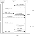
- FIG. 3 is a schematic structural diagram of a base station.
- the base station shown in FIG. 3 may be a distributed base station.
- a distributed base station including an antenna (antennas), a remote radio unit (RRU for short), and a baseband unit (BBU for short) is shown.
- the base station shown in FIG. 3 may be an integrated base station such as a small cell shown on the right of FIG. 3 .
- the base station includes a part 201 and a part 202.
- the part 201 is mainly configured to: receive and send a radio frequency signal, and convert the radio frequency signal and a baseband signal.
- the part 202 is mainly configured to: perform baseband processing, control the base station, and the like.
- the part 201 may be usually referred to as a transceiver unit, a transceiver machine, a transceiver circuit, a transceiver, or the like.
- the part 202 may be usually referred to as a processing unit.
- the part 202 is a control center of the base station.
- the part 201 may include an antenna and a radio frequency unit.
- the radio frequency unit is mainly configured to perform radio frequency processing.
- a component that is in the part 201 and configured to implement a receiving function may be considered as a receiving unit
- a component that is in the part 201 and configured to implement a sending function may be considered as a sending unit. That is, the part 201 includes the receiving unit and the sending unit.
- the receiving unit may also be referred to as a receiver machine, a receiver, or a receiver circuit
- the sending unit may be referred to as a transmitter machine, a transmitter, or a transmit circuit.
- the part 202 may include one or more boards.
- Each board may include a processor and a memory, and the processor is configured to read and execute a program in the memory to implement a baseband processing function and control the base station. If there are multiple boards, the boards may be interconnected to enhance a processing capability.
- functions of the part 202 and the part 201 may be implemented by using the SoC technology, that is, the functions of the part 202 and the part 201 may be implemented by using a functional chip of the base station.
- the functional chip of the base station integrates components such as the processor, the memory, and the antenna.
- a program having related functions of the base station is stored in the memory, and the processor executes the program to implement the related functions of the base station.
- the UE 1 may communicate with the base station by using the UE 2, that is, the UE 1 may exchange both uplink data and downlink data with the base station by using the UE 2. Because quality of a signal between the UE 2 and the base station or between the UE 2 and the UE 1 may be poorer due to movement of the UE 2, or a case such as power off or a fault may occur in a relay process, network reliability may decrease when a relay function is implemented by using the user equipment.
- An embodiment of the present invention provides a data transmission method.
- UE sends uplink data to a base station by using a UE-relay.
- the UE-relay may also be referred to as an uplink UE-relay or an uplink UE-relay. That is, a transmission path of the uplink data of the UE is UE ⁇ (uplink UE-relay) ⁇ BS.
- a sending unit of the UE may be configured to send the uplink data to the base station by using the UE-relay
- a transceiver unit of the base station (or a receiving unit in a transceiver unit of the base station) may be configured to receive the uplink data of the UE by using the UE-relay.
- the UE receives downlink data sent by the base station.
- a receiving unit of the UE may be configured to receive the downlink data sent by the base station, and the transceiver unit of the base station (or a sending unit in the transceiver unit of the base station) may be configured to send the downlink data to the UE.
- the UE may receive, from the base station, the downlink data sent by the base station. That is, a transmission path of the downlink data is BS ⁇ UE, and a transmission path of the uplink data is UE ⁇ (uplink UE-relay)-BS.
- the uplink UE-relay may be any UE having a relay function in the network, for example, the UE 2 or the UE 3.
- the transmission path of the uplink data between the UE and the base station is different from the transmission path of the downlink data between the UE and the base station.
- the UE-relay is used only on a link of the uplink data, so as to reduce impact of the UE-relay on network reliability, and improve reliability of a network using a D2D technology.
- the UE may also receive, by using the UE-relay, the downlink data sent by the base station.
- the UE-relay may also be referred to as a downlink UE-relay or a downlink UE-relay. That is, in this example, a transmission path of the uplink data is UE ⁇ (uplink UE-relay)-BS, and a transmission path of the downlink data is BS ⁇ (downlink UE-relay)-UE.
- the receiving unit of the UE may be configured to receive, by using the UE-relay, the downlink data sent by the base station, and the transceiver unit of the base station (or the sending unit in the transceiver unit of the base station) may be configured to send the downlink data to the downlink UE-relay.
- the UE may still perform uplink transmission and downlink transmission with the base station by using the uplink UE-relay and the downlink UE-relay. That is, a distance of communication between the UE and the base station increases.
- the downlink UE-relay and the uplink UE-relay are acted by different user equipments.
- the uplink UE-relay is another UE other than the UE 2, for example, the UE 3.
- different UE-relays are separately used as the uplink UE-relay and the downlink UE-relay, so as to avoid impact exerted by movement of a single UE-relay or a communication fault on communication between the UE and the base station, and improve reliability of a network using a D2D technology.
- quality of communication between the downlink UE-relay and the base station is better than quality of communication between the UE and the base station.
- quality of service Quality of Service, QoS
- QoS Quality of Service
- a distance between the UE and the uplink UE-relay may be shorter than a distance between the UE and the base station.
- transmit power required for sending the uplink data to the uplink UE-relay by the UE is less than transmit power required for sending the uplink data to the base station by the UE, so as to help reduce power consumption of the UE, and implement power saving.
- the uplink UE-relay may send a downlink reply of the uplink UE-relay to the uplink data, such as an ACK/NACK, to the UE.
- the receiving unit of the UE may be configured to receive the downlink reply.
- a reply may also be expressed as a response.
- the UE may send a reply to the downlink data, such as an ACK/NACK, to the downlink UE-relay.
- the sending unit of the UE may be configured to send the reply to the downlink UE-relay.
- communication between the UE and the user equipment relay may be performed in a unicast or broadcast manner.
- the UE After the UE receives the downlink data sent by the base station, the UE needs to send the reply to the downlink data to the base station on a PUCCH resource allocated by the base station to the UE, so that the base station can learn that the reply is sent by the UE for the downlink data.
- the reply may be understood as one type of the uplink data sent by the UE to the base station.
- the UE may send first indication information to the uplink UE-relay.
- the first indication information is used to indicate a PUCCH resource corresponding to the UE.
- the sending unit of the UE may be configured to send the first indication information.
- the PUCCH resource corresponding to the UE may be expressed as a PUCCH resource allocated to the UE, or a PUCCH resource configured for the UE.
- the uplink UE-relay After receiving the PUCCH resource, the uplink UE-relay sends a reply of the UE to the base station by using the PUCCH resource. After the base station receives the reply on the PUCCH resource, the base station considers that the reply is sent by the UE for the downlink data.
- the first indication information includes may include n CCE and N PUCCH 1 , where n CCE is used to indicate a number of a first control channel element (CCE for short) that is in a physical downlink control channel (PDCCH for short) and that is used to indicate downlink transmission, and N PUCCH 1 is used to indicate a UE-dedicated PUCCH ACK/NACK offset or used to indicate a PUCCH format 1a/1b start offset used for a subframe set K2.
- CCE first control channel element
- PDCCH physical downlink control channel
- Table 1 Mapping of ACK/NACK resource offset field in DCI format 1A/1B/1D/1/2A/2/2B/2C/2D to ⁇ ARO values (Mapping of ACK/NACK resource offset field in DCI format 1A/1B/1D/1/2A/2/2B/2C/2D to ⁇ ARO values) ACK/NACK resource offset field in DCI format 1A/1B/1D/1/2A/2/2B/2C/2D (ACK/NACK resource offset field in DCI format 1A/1B/1D/1/2A/2/2B/2C/2D) ⁇ ARO 0 0 1 -1 2 -2 3 2
- the first indication information may include n ECCE,q , ⁇ ARO , N PUCCH , q e 1 , and n' .
- n ECCE,q , ⁇ ARO , and N PUCCH , q e 1 refer to the foregoing content. Details are not described herein again.
- n' is used to indicate a value of an antenna port used for centralized EPDCCH transmission (for a specific value of n' , refer to Table 2).
- Antenna port to use for localized EPDCCH transmission (Antenna port used for centralized enhanced physical downlink control channel transmission) n' Normal cyclic prefix (Normal cyclic prefix) Extended cyclic prefix (Extended cyclic prefix) Normal subframes, special subframes, and configurations 3, 4, 8 (Normal subframes, special subframes, and configurations 3, 4, and 8) Special subframes, and configurations 1, 2, 6, 7, 9 (Special subframes, and configurations 1, 2, 6, 7, and 9) Any subframe (Any subframe) 0 107 107 107 1 108 109 108 2 109 - - 3 110 - - -
- n CCE , N PUCCH 1 , n ECCE,q , ⁇ ARO , N PUCCH , q e 1 , and n' that are included in the first indication information, refer to content in the chapter 10.1.2.1 in the 3GPP standard: 3GPP TS 36.213 v12.5.0. Details are not described herein.
- n CCE , N PUCCH 1 , n ECCE,q , ⁇ ARO N PUCCH , q e 1 , and n' that are included in the first indication information may be applied to an LTE FDD (frequency division duplex) network.
- the following parameters included in the first indication information may be applied to an LTE TDD (time division duplex) network.
- LTE TDD time division duplex
- the first indication information may include M, m, n CCE , and N PUCCH 1 .
- the first indication information may include n ECCE,q , N PUCCH , q e 1 , m, N ECCE,q,n-k i 1 , and ⁇ ARO.
- the first indication information may include n ECCE,q , N PUCCH , q e 1 , m, n' , ⁇ ARO , and N ECCE,q,n-k i 1 .
- N ECCE,q,n-k i1 that are included in the first indication information and may be applied to the LTE TDD network, refer to content in the chapter 10.1.3.1 in the 3GPP standard: 3GPP TS 36.213 v12.5.0. Details are not described herein.
- the first indication information may further include n PUCCH 2 p ⁇ .
- n PUCCH 2 p ⁇ is used to indicate an index of a CQI allocated to the UE.
- the uplink UE-relay may send, to the base station by using the first indication information, both the reply of the UE to the uplink data and the CQI fed back by the UE.
- the base station may receive the reply (or the reply and the periodic CQI) on the PUCCH resource after a delay of m transmission time intervals (transmission time interval, TTI for short).
- TTI transmission time interval
- the transceiver unit of the base station (or the receiving unit in the transceiver unit of the base station) may be configured to receive the uplink data on the PUCCH resource. Further, the transceiver unit of the base station may receive the uplink data on the PUCCH resource after the delay of m TTIs.
- the m TTIs are greater than or equal to a time required when the user equipment sends the second indication information and the reply to the downlink data to the uplink UE-relay. In this way, a HARQ procedure is less affected.
- the base station After the uplink UE-relay forwards the uplink data of the UE to the base station, the base station sends a reply to the uplink data. Because the uplink data is sent by the uplink UE-relay to the base station, the base station sends the reply on a physical hybrid automatic repeat request indicator channel (PHICH for short) resource corresponding to the uplink UE-relay, so that the uplink UE-relay can receive the reply.
- PHICH physical hybrid automatic repeat request indicator channel
- a person skilled in the art may understand that the PHICH resource corresponding to the uplink UE-relay may be expressed as a PHICH resource allocated to the uplink UE-relay, or a PHICH resource configured for the uplink UE-relay.
- the uplink UE-relay may notify the UE of the PHICH resource corresponding to the uplink UE-relay.
- the UE may receive the reply to the uplink data from the base station according to the PHICH resource.
- the receiving unit of the UE may be configured to receive second indication information from the uplink UE-relay.
- the second indication information is used to indicate the PHICH resource corresponding to the uplink UE-relay.
- the second indication information may include n DMRS and I PRB _ RA lowest _ index , where n DMRS is used to indicate a DMRS offset, and I PRB _ RA lowest _ index is used to indicate a minimum index of a PRB for uplink transmission.
- n DMRS is used to indicate a DMRS offset
- I PRB _ RA lowest _ index is used to indicate a minimum index of a PRB for uplink transmission.
- FIG. 4 With reference to the network shown in FIG. 1 , the method shown in FIG. 4 is further described in a scenario A and a scenario B below.
- the uplink UE-relay is the UE 2
- the user equipment UE 1 sends uplink data to the base station by using the UE 2
- the UE 1 directly receives downlink data from the base station.
- the UE 1 sends uplink data to the UE 2.
- the UE 1 may send the uplink data to the UE 2 in a unicast or broadcast manner.
- the UE 2 sends a reply to the uplink data to the UE 1.
- the reply may be an ACK or a NACK.
- the UE 1 may resend the uplink data to the UE 2.
- the UE 2 sends the uplink data to the base station.
- the UE 2 may send the uplink data to the base station by using a physical uplink shared channel (PUSCH for short) resource configured by the base station for the UE 2.
- PUSCH physical uplink shared channel
- the PUSCH resource may be obtained by the UE 2 by using a scheduling request (SR for short). S505.
- the base station sends a reply to the uplink data.
- the base station sends the reply according to a PHICH resource allocated to the UE 2.
- the reply sent by the base station on the PHICH resource may be received by the UE 2 (refer to S5051), or may be received by the UE 1 (refer to S504 and S5052).
- the UE 2 receives the reply of the base station to the uplink data on a PHICH resource allocated by the base station to the UE 2.
- the UE 2 sends second indication information to the UE 1, where the second indication information is used to indicate the PHICH resource.
- the UE 1 may receive the reply of the base station to the uplink data on the PHICH resource.
- the second indication information refer to the second indication information in FIG. 4 . Details are not described herein again.
- the UE 1 receives the reply of the base station to the uplink data on the PHICH resource allocated by the base station to the UE 2.
- S501 to S505 provide a specific implementation of S402 as an example.
- S506 to S510 provide a specific implementation of S401 as an example.
- the base station sends downlink data to the UE 1.
- the base station sends the downlink data to the UE 1 by using a physical downlink shared channel (PDSCH for short) resource.
- PDSCH physical downlink shared channel
- the UE 1 sends first indication information to the UE 2.
- the first indication information is used to indicate a PUCCH resource corresponding to the UE 1, that is, a PUCCH resource configured for the UE 1.
- a PUCCH resource corresponding to the UE 1 that is, a PUCCH resource configured for the UE 1.
- For the first indication information refer to the first indication information in FIG. 4 . Details are not described herein again.
- the UE 1 sends a reply to the downlink data to the UE 2.
- the UE 1 may further send a periodic CQI to the UE 2.
- a sequence between S507 and S508 is not limited.
- the UE 1 may send the second indication information, the reply to the downlink data, or the periodic CQI to the UE 2 in a broadcast or unicast manner.
- the UE 2 sends a reply to the first indication information, a reply to the downlink data, or a reply to the periodic CQI to the UE 1.
- the UE 2 sends the reply of the UE 1 to the downlink data to the base station.
- the UE 2 sends the reply of the UE 1 to the downlink data to the base station according to the PUCCH resource configured for the UE 1.
- uplink data and downlink data are transmitted in different transmission paths, so as to reduce impact of a user equipment relay on transmission reliability.
- the base station may further contact the user equipment in a downlink, so as to perform subsequent remedies, and improve network reliability.
- the downlink UE-relay is the UE 3, and the uplink UE-realy is the UE 2.
- the UE 1 sends uplink data to the base station by using the UE 2, and receives downlink data from the base station by using the UE 3.
- the UE 1 may be in coverage of the base station or may be outside coverage of the base station.
- the UE 1 sends uplink data by using the UE 2.
- S602 to S605 provide one of specific implementations of S401 as an example.
- the base station sends downlink data to the UE 3.
- the base station sends the downlink data to the UE 3 by using a PDSCH resource in S602.
- the UE 3 sends a reply of the UE 3 to the downlink data to the base station.
- the UE 3 may send the reply to the downlink data to the base station according to a PUCCH resource configured for the UE 3.
- the UE 3 sends the downlink data to the UE 1.
- the UE 3 may send the downlink data to the UE 1 in a broadcast or unicast manner.
- the UE 1 sends a reply of the UE 1 to the downlink data to the UE 3.
- different user equipment relays separately forward the uplink data and the downlink data of the user equipment, so as to reduce impact of a fault of a single user equipment relay on a network, and improve network reliability.
- an embodiment of the present invention further provides user equipment.
- For a structure of the user equipment refer to FIG. 2 .
- an embodiment of the present invention further provides user equipment, and the user equipment is used as a user equipment relay.
- the user equipment For a structure of the user equipment, refer to FIG. 2 .
- a mechanism used by the user equipment to implement an objective of this embodiment of the present invention refer to the UE 2 in the foregoing embodiments. Details are not described herein again.
- an embodiment of the present invention further provides a base station.
- a structure of the base station refer to FIG. 3 .
- a mechanism used by the base station to implement an objective of this embodiment of the present invention refer to the base station in the foregoing embodiments. Details are not described herein again.
- an embodiment of the present invention further provides a data transmission system, so as to implement an objective of this embodiment of the present invention.
- the system may include UE 1 and UE 2, and may further include a base station or UE 3.
- UE 1 and UE 2 may further include a base station or UE 3.
- the various illustrative logical units and circuits described in the embodiments of the present invention may implement or operate the described functions by using a general purpose processor, a digital signal processor, an application-specific integrated circuit (ASIC), a field programmable gate array (FPGA) or another programmable logic apparatus, a discrete gate or transistor logic, a discrete hardware component, or a design of any combination thereof.
- the general purpose processor may be a microprocessor.
- the general purpose processor may be any conventional processor, controller, microcontroller, or state machine.
- the processor may also be implemented by a combination of computing apparatuses such as a digital signal processor and a microprocessor, multiple microprocessors, one or more microprocessors with a digital signal processor core, or any other similar configuration.
- Steps of the methods or algorithms described in the embodiments of the present invention may be directly embedded into hardware, a software unit executed by a processor, or a combination thereof.
- the software unit may be stored in a RAM memory, a flash memory, a ROM memory, an EPROM memory, an EEPROM memory, a register, a hard disk, a removable magnetic disk, a CD-ROM, or a storage medium of any other form in the art.
- the storage medium may connect to a processor, so that the processor may read information from the storage medium and write information to the storage medium.
- the storage medium may be integrated into the processor.
- the processor and the storage medium may be arranged in an ASIC, and the ASIC may be arranged in UE.
- the processor and the storage medium may be arranged in different components of the UE.
- the functions described in the embodiments of the present invention may be implemented by using hardware, software, firmware, or any combination thereof. If being implemented by using the software, these functions may be stored in a computer-readable medium or are transmitted to the computer-readable medium in a form of one or more instructions or code.
- the computer-readable medium includes a computer storage medium and a communications medium that enables a computer program to move from one location to another.
- the storage medium may be an available medium that may be accessed by any general or special computer.
- such a computer-readable medium may include but is not limited to a RAM, a ROM, an EEPROM, a CD-ROM or another optical disc storage, a disk storage or another magnetic storage apparatus, or any other media that may be used to carry or store program code that is in a form of an instruction or a data structure or in a form that can be read by a general or special computer or by a general or special processor.
- any connection may be appropriately defined as a computer-readable medium.
- the software is included in a defined computer-readable medium.
- the disc (disk) and the disk (disc) include a compressed disk, a laser disk, an optical disc, a DVD, a floppy disk, and a Blu-ray disc.
- the disk generally copies data in a magnetic manner, and the disc generally copies data optically in a laser manner.
- the foregoing combination may also be included in the computer-readable medium.
Landscapes
- Engineering & Computer Science (AREA)
- Computer Networks & Wireless Communication (AREA)
- Signal Processing (AREA)
- Mobile Radio Communication Systems (AREA)
Claims (10)
- Datenübertragungsverfahren, umfassend:Senden (S401) von Aufwärtsstreckendaten zu einer Basisstation durch eine Benutzereinrichtung UE durch Verwendung eines Aufwärtsstrecken-Benutzereinrichtungsrelais bzw. Aufwärtsstrecken-UE-Relais;Empfangen (S402) von Abwärtsstreckendaten von der Basisstation durch die UE; gekennzeichnet durchSenden von ersten Angabeinformationen zu dem Aufwärtsstrecken-UE-Relais durch die UE, wobei die ersten Angabeinformationen verwendet werden, um eine der UE entsprechende Aufwärtsstrecken-Übertragungsressource anzugeben, sodass das Aufwärtsstrecken-UE-Relais die Aufwärtsstreckendaten gemäß der Aufwärtsstrecken-Übertragungsressource zu der Basisstation sendet; undEmpfangen von zweiten Angabeinformationen von dem Aufwärtsstrecken-UE-Relais durch die UE, wobei die zweiten Angabeinformationen verwendet werden, um eine dem Aufwärtsstrecken-UE-Relais entsprechende Abwärtsstrecken-Übertragungsressource anzugeben, wobeidie Aufwärtsstrecken-Übertragungsressource eine "Physical Uplink Control Channel"- bzw. PUCCH-Ressource umfasst; unddie ersten Angabeinformationen n CCE und


- Verfahren nach Anspruch 1, ferner umfassend:
Empfangen einer Antwort des Aufwärtsstrecken-UE-Relais auf die Aufwärtsstreckendaten von dem Aufwärtsstrecken-UE-Relais durch die UE. - Verfahren nach Anspruch 2, wobei, wenn die UE die Abwärtsstreckendaten durch Verwendung des Abwärtsstrecken-UE-Relais von der Basisstation empfängt, das Verfahren ferner Folgendes umfasst:
Senden einer Antwort der UE auf die Abwärtsstreckendaten zu dem Abwärtsstrecken-UE-Relais durch die UE. - Datenübertragungsverfahren, umfassend:Empfangen von Aufwärtsstreckendaten einer Benutzereinrichtung UE durch eine Basisstation durch Verwendung eines Aufwärtsstrecken-Benutzereinrichtungsrelais bzw. Aufwärtsstrecken-UE-Relais, dadurch gekennzeichnet, dass die Basisstation die Aufwärtsstreckendaten gemäß einer Aufwärtsstrecken-Übertragungsressource empfängt, die in von der UE zu dem UE-Relais gesendeten ersten Angabeinformationen enthalten ist; undSenden von Abwärtsstreckendaten zu der UE durch die Basisstation, wobei die Aufwärtsstrecken-Übertragungsressource eine "Physical Uplink Control Channel"- bzw. PUCCH-Ressource umfasst; unddie ersten Angabeinformationen n CCE und


- Vorrichtung, wobei die Vorrichtung dafür ausgelegt ist, das Verfahren nach einem der Ansprüche 1 bis 3 auszuführen.
- Vorrichtung, wobei die Vorrichtung dafür ausgelegt ist, das Verfahren nach Anspruch 4 auszuführen.
- Computerlesbares Speicherungsmedium, das eine Anweisung umfasst, die, wenn sie durch eine Computervorrichtung ausgeführt wird, bewirkt, dass die Computervorrichtung das Verfahren nach einem der Ansprüche 1 bis 3 ausführt.
- Computerlesbares Speicherungsmedium, das eine Anweisung umfasst, die, wenn sie durch eine Computervorrichtung ausgeführt wird, bewirkt, dass die Computervorrichtung das Verfahren nach Anspruch 4 ausführt.
- Computerprogrammprodukt, das eine Anweisung umfasst, die, wenn sie durch eine Computervorrichtung ausgeführt wird, bewirkt, dass die Computervorrichtung das Verfahren nach einem der Ansprüche 1 bis 3 ausführt.
- Computerprogrammprodukt, das eine Anweisung umfasst, die, wenn sie durch eine Computervorrichtung ausgeführt wird, bewirkt, dass die Computervorrichtung das Verfahren nach Anspruch 4 ausführt.
Priority Applications (1)
| Application Number | Priority Date | Filing Date | Title |
|---|---|---|---|
| EP22181731.5A EP4124168B1 (de) | 2015-08-12 | 2015-08-12 | Datenübertragungsverfahren, benutzergerät und basisstation |
Applications Claiming Priority (3)
| Application Number | Priority Date | Filing Date | Title |
|---|---|---|---|
| PCT/CN2015/086807 WO2017024569A1 (zh) | 2015-08-12 | 2015-08-12 | 一种数据传输方法、用户设备和基站 |
| EP15900767.3A EP3324679A4 (de) | 2015-08-12 | 2015-08-12 | Datenübertragungsverfahren, benutzergerät und basisstation |
| EP22181731.5A EP4124168B1 (de) | 2015-08-12 | 2015-08-12 | Datenübertragungsverfahren, benutzergerät und basisstation |
Related Parent Applications (1)
| Application Number | Title | Priority Date | Filing Date |
|---|---|---|---|
| EP15900767.3A Division EP3324679A4 (de) | 2015-08-12 | 2015-08-12 | Datenübertragungsverfahren, benutzergerät und basisstation |
Publications (2)
| Publication Number | Publication Date |
|---|---|
| EP4124168A1 EP4124168A1 (de) | 2023-01-25 |
| EP4124168B1 true EP4124168B1 (de) | 2025-05-21 |
Family
ID=57983986
Family Applications (2)
| Application Number | Title | Priority Date | Filing Date |
|---|---|---|---|
| EP22181731.5A Active EP4124168B1 (de) | 2015-08-12 | 2015-08-12 | Datenübertragungsverfahren, benutzergerät und basisstation |
| EP15900767.3A Withdrawn EP3324679A4 (de) | 2015-08-12 | 2015-08-12 | Datenübertragungsverfahren, benutzergerät und basisstation |
Family Applications After (1)
| Application Number | Title | Priority Date | Filing Date |
|---|---|---|---|
| EP15900767.3A Withdrawn EP3324679A4 (de) | 2015-08-12 | 2015-08-12 | Datenübertragungsverfahren, benutzergerät und basisstation |
Country Status (4)
| Country | Link |
|---|---|
| US (1) | US10779284B2 (de) |
| EP (2) | EP4124168B1 (de) |
| CN (2) | CN111741505B (de) |
| WO (1) | WO2017024569A1 (de) |
Families Citing this family (7)
| Publication number | Priority date | Publication date | Assignee | Title |
|---|---|---|---|---|
| GB201520008D0 (en) * | 2015-11-12 | 2015-12-30 | Telensa Ltd | Methods and apparatus for transmitting data in a network |
| JP6910363B2 (ja) * | 2016-09-30 | 2021-07-28 | 京セラ株式会社 | 通信制御方法 |
| KR102491548B1 (ko) | 2017-07-31 | 2023-01-26 | 삼성전자주식회사 | 지시 정보 검출 방법과 장치, 및 전송 중계 방법 및 기기 |
| CN110087340B (zh) * | 2018-01-25 | 2024-04-05 | 北京三星通信技术研究有限公司 | 中继传输的方法及设备 |
| US10419077B1 (en) * | 2018-03-28 | 2019-09-17 | Google Llc | Wireless communication via a mobile relay |
| CN110519022B (zh) * | 2019-08-30 | 2021-06-18 | 北京紫光展锐通信技术有限公司 | 数据传输方法、用户终端及计算机可读存储介质 |
| WO2022246726A1 (en) * | 2021-05-27 | 2022-12-01 | Qualcomm Incorporated | Channel information exchange for user equipment cooperation |
Family Cites Families (27)
| Publication number | Priority date | Publication date | Assignee | Title |
|---|---|---|---|---|
| JP3768992B2 (ja) * | 2001-10-03 | 2006-04-19 | 株式会社エヌ・ティ・ティ・ドコモ | 中継端末、基地局、課金サーバ、通信システム、課金方法、プログラム、コンピュータデータ信号及び記憶媒体 |
| GB0616476D0 (en) * | 2006-08-18 | 2006-09-27 | Fujitsu Ltd | Communication systems |
| KR100975732B1 (ko) * | 2006-08-31 | 2010-08-12 | 삼성전자주식회사 | 통신 시스템에서 자원 할당 정보 전송 방법 및 시스템 |
| US8619663B2 (en) * | 2009-01-22 | 2013-12-31 | Lg Electronics Inc. | Apparatus and method for cooperatively transmitting downlink between base station and relay station |
| US8780784B2 (en) * | 2009-05-29 | 2014-07-15 | Lg Electronics Inc. | Method and apparatus for transmitting control information from relay node on backhaul uplink |
| CN101908955A (zh) * | 2009-06-05 | 2010-12-08 | 大唐移动通信设备有限公司 | 一种回程链路下行信息传输方法及设备 |
| JP5559786B2 (ja) * | 2009-06-25 | 2014-07-23 | 株式会社日立製作所 | 基地局、無線通信システム、無線リソース割り当て方法、ならびに無線通信方法 |
| JP5310354B2 (ja) * | 2009-07-23 | 2013-10-09 | ソニー株式会社 | 基地局、通信システム、移動端末および中継装置 |
| US20110035294A1 (en) * | 2009-08-04 | 2011-02-10 | Authernative, Inc. | Multi-tier transaction processing method and payment system in m- and e- commerce |
| JP2011066874A (ja) * | 2009-08-17 | 2011-03-31 | Sony Corp | 通信システム、通信装置及び通信方法、並びにコンピューター・プログラム |
| US9350508B2 (en) * | 2010-01-18 | 2016-05-24 | Telefonaktiebolaget Lm Ericsson (Publ) | Method and arrangement in a wireless communication network |
| US8934333B2 (en) * | 2010-08-10 | 2015-01-13 | Lg Electronics Inc. | Method and device for transmitting/receiving data in wireless communication system supporting relay node |
| US20130016649A1 (en) * | 2011-07-12 | 2013-01-17 | Qualcomm Incorporated | System design for user equipment relays |
| GB2493784B (en) * | 2011-08-19 | 2016-04-20 | Sca Ipla Holdings Inc | Wireless communications system and method |
| CN103188706A (zh) * | 2011-12-29 | 2013-07-03 | 上海贝尔股份有限公司 | 一种用户终端之间进行协作传输的方法和装置 |
| WO2014014164A1 (en) * | 2012-07-15 | 2014-01-23 | Lg Electronics Inc. | Method and apparatus for subset network coding with multiple antennas by relay node in wireless communication system |
| CN102780993B (zh) * | 2012-08-20 | 2015-04-15 | 哈尔滨工业大学 | Td_lte_a系统中终端d2d协作中继通信实现方法 |
| US9131498B2 (en) | 2012-09-12 | 2015-09-08 | Futurewei Technologies, Inc. | System and method for adaptive transmission time interval (TTI) structure |
| US9019841B2 (en) * | 2012-10-19 | 2015-04-28 | Qualcomm Incorporated | Architecture for relays in LTE using D2D |
| US9072000B2 (en) * | 2012-10-19 | 2015-06-30 | Qualcomm Incorporated | Power efficient relay discovery protocol |
| US9641237B2 (en) * | 2013-01-11 | 2017-05-02 | Centre Of Excellence In Wireless Technology | Indoor personal relay |
| US8873455B2 (en) * | 2013-02-15 | 2014-10-28 | General Dynamics C4 Systems, Inc. | Communication units and methods for relay-assisted uplink communication |
| US9900931B2 (en) * | 2013-05-02 | 2018-02-20 | Qualcomm Incorporated | Method and apparatus for device to device relay selection |
| CN103684715A (zh) * | 2013-09-27 | 2014-03-26 | 北京邮电大学 | 一种基于中继的d2d簇合作重传方法及其实现装置 |
| WO2015093560A1 (ja) * | 2013-12-20 | 2015-06-25 | 京セラ株式会社 | 移動通信システム、無線通信装置、ネットワーク装置、及び無線端末 |
| KR102153587B1 (ko) * | 2014-04-03 | 2020-09-09 | 한국전자통신연구원 | 이종 네트워크에서의 데이터 전송 방법 및 장치 |
| AU2015331962B2 (en) * | 2014-10-15 | 2018-05-10 | Nec Corporation | Radio relay station, radio base station, communication system and communication method |
-
2015
- 2015-08-12 EP EP22181731.5A patent/EP4124168B1/de active Active
- 2015-08-12 EP EP15900767.3A patent/EP3324679A4/de not_active Withdrawn
- 2015-08-12 CN CN202010403872.8A patent/CN111741505B/zh active Active
- 2015-08-12 WO PCT/CN2015/086807 patent/WO2017024569A1/zh not_active Ceased
- 2015-08-12 CN CN201580072970.5A patent/CN107211339B/zh active Active
-
2018
- 2018-02-09 US US15/892,419 patent/US10779284B2/en active Active
Also Published As
| Publication number | Publication date |
|---|---|
| US10779284B2 (en) | 2020-09-15 |
| WO2017024569A1 (zh) | 2017-02-16 |
| CN107211339A (zh) | 2017-09-26 |
| EP3324679A4 (de) | 2018-08-08 |
| EP4124168A1 (de) | 2023-01-25 |
| EP3324679A1 (de) | 2018-05-23 |
| CN111741505B (zh) | 2025-02-21 |
| CN111741505A (zh) | 2020-10-02 |
| US20180167928A1 (en) | 2018-06-14 |
| CN107211339B (zh) | 2020-05-08 |
Similar Documents
| Publication | Publication Date | Title |
|---|---|---|
| EP3961935B1 (de) | Strahlkonfigurationsverfahren, -vorrichtungen, computerlesbare speichermedien und computerprogrammprodukte | |
| EP4124168B1 (de) | Datenübertragungsverfahren, benutzergerät und basisstation | |
| US9521669B2 (en) | HARQ for dynamic change of the TDD UL/DL configuration in LTE TDD systems | |
| EP4193542B1 (de) | System und verfahren zur pucch-verbesserung mit intra-slot-wiederholungen in richtung mehrerer trps | |
| EP3364591B1 (de) | Verfahren und vorrichtung zur übertragung von tdd-systeminformationen | |
| EP3745630B1 (de) | Verfahren und vorrichtung | |
| US20110176461A1 (en) | Determining configuration of subframes in a radio communications system | |
| US11445531B2 (en) | Communication method, communications apparatus, and readable storage medium | |
| US20140198773A1 (en) | Systems and methods for special subframe configuration for carrier aggregation | |
| CN102158325B (zh) | 数据传输方法及装置 | |
| EP2824861B1 (de) | Verfahren zur Handhabung von HARQ-Feedbacks | |
| WO2014007580A1 (ko) | 무선 통신 시스템에서 d2d(device-to-device) 통신을 위한 버퍼 운영 방법 및 이를 위한 장치 | |
| US10454630B2 (en) | Information transmission method, and user equipment and base station | |
| JP2015524187A (ja) | カバレッジを増大させるための方法及び装置 | |
| EP2719239A1 (de) | Neuübertragungen in einem kommunikationssystem mit weitgehend leeren subframes | |
| EP4195832A1 (de) | Verfahren und vorrichtung zur anzeige von ressourcenmultiplexing und relaisknoten | |
| EP3634059B1 (de) | Verfahren und vorrichtung zur übertragung von informationen | |
| WO2017024467A1 (zh) | 无线通信的方法、网络设备和终端设备 | |
| WO2014075320A1 (en) | Method and apparatus |
Legal Events
| Date | Code | Title | Description |
|---|---|---|---|
| PUAI | Public reference made under article 153(3) epc to a published international application that has entered the european phase |
Free format text: ORIGINAL CODE: 0009012 |
|
| STAA | Information on the status of an ep patent application or granted ep patent |
Free format text: STATUS: THE APPLICATION HAS BEEN PUBLISHED |
|
| AC | Divisional application: reference to earlier application |
Ref document number: 3324679 Country of ref document: EP Kind code of ref document: P |
|
| AK | Designated contracting states |
Kind code of ref document: A1 Designated state(s): AL AT BE BG CH CY CZ DE DK EE ES FI FR GB GR HR HU IE IS IT LI LT LU LV MC MK MT NL NO PL PT RO RS SE SI SK SM TR |
|
| STAA | Information on the status of an ep patent application or granted ep patent |
Free format text: STATUS: REQUEST FOR EXAMINATION WAS MADE |
|
| 17P | Request for examination filed |
Effective date: 20230406 |
|
| RBV | Designated contracting states (corrected) |
Designated state(s): AL AT BE BG CH CY CZ DE DK EE ES FI FR GB GR HR HU IE IS IT LI LT LU LV MC MK MT NL NO PL PT RO RS SE SI SK SM TR |
|
| GRAP | Despatch of communication of intention to grant a patent |
Free format text: ORIGINAL CODE: EPIDOSNIGR1 |
|
| STAA | Information on the status of an ep patent application or granted ep patent |
Free format text: STATUS: GRANT OF PATENT IS INTENDED |
|
| RIC1 | Information provided on ipc code assigned before grant |
Ipc: H04W 72/04 20230101ALI20250115BHEP Ipc: H04W 40/22 20090101ALI20250115BHEP Ipc: H04W 88/04 20090101AFI20250115BHEP |
|
| INTG | Intention to grant announced |
Effective date: 20250123 |
|
| GRAS | Grant fee paid |
Free format text: ORIGINAL CODE: EPIDOSNIGR3 |
|
| GRAA | (expected) grant |
Free format text: ORIGINAL CODE: 0009210 |
|
| STAA | Information on the status of an ep patent application or granted ep patent |
Free format text: STATUS: THE PATENT HAS BEEN GRANTED |
|
| AC | Divisional application: reference to earlier application |
Ref document number: 3324679 Country of ref document: EP Kind code of ref document: P |
|
| AK | Designated contracting states |
Kind code of ref document: B1 Designated state(s): AL AT BE BG CH CY CZ DE DK EE ES FI FR GB GR HR HU IE IS IT LI LT LU LV MC MK MT NL NO PL PT RO RS SE SI SK SM TR |
|
| REG | Reference to a national code |
Ref country code: GB Ref legal event code: FG4D |
|
| REG | Reference to a national code |
Ref country code: CH Ref legal event code: EP |
|
| REG | Reference to a national code |
Ref country code: DE Ref legal event code: R096 Ref document number: 602015091730 Country of ref document: DE |
|
| REG | Reference to a national code |
Ref country code: IE Ref legal event code: FG4D |
|
| REG | Reference to a national code |
Ref country code: NL Ref legal event code: MP Effective date: 20250521 |
|
| PG25 | Lapsed in a contracting state [announced via postgrant information from national office to epo] |
Ref country code: PT Free format text: LAPSE BECAUSE OF FAILURE TO SUBMIT A TRANSLATION OF THE DESCRIPTION OR TO PAY THE FEE WITHIN THE PRESCRIBED TIME-LIMIT Effective date: 20250922 Ref country code: ES Free format text: LAPSE BECAUSE OF FAILURE TO SUBMIT A TRANSLATION OF THE DESCRIPTION OR TO PAY THE FEE WITHIN THE PRESCRIBED TIME-LIMIT Effective date: 20250521 Ref country code: FI Free format text: LAPSE BECAUSE OF FAILURE TO SUBMIT A TRANSLATION OF THE DESCRIPTION OR TO PAY THE FEE WITHIN THE PRESCRIBED TIME-LIMIT Effective date: 20250521 |
|
| REG | Reference to a national code |
Ref country code: LT Ref legal event code: MG9D |
|
| PG25 | Lapsed in a contracting state [announced via postgrant information from national office to epo] |
Ref country code: GR Free format text: LAPSE BECAUSE OF FAILURE TO SUBMIT A TRANSLATION OF THE DESCRIPTION OR TO PAY THE FEE WITHIN THE PRESCRIBED TIME-LIMIT Effective date: 20250822 Ref country code: NO Free format text: LAPSE BECAUSE OF FAILURE TO SUBMIT A TRANSLATION OF THE DESCRIPTION OR TO PAY THE FEE WITHIN THE PRESCRIBED TIME-LIMIT Effective date: 20250821 |
|
| PG25 | Lapsed in a contracting state [announced via postgrant information from national office to epo] |
Ref country code: PL Free format text: LAPSE BECAUSE OF FAILURE TO SUBMIT A TRANSLATION OF THE DESCRIPTION OR TO PAY THE FEE WITHIN THE PRESCRIBED TIME-LIMIT Effective date: 20250521 Ref country code: NL Free format text: LAPSE BECAUSE OF FAILURE TO SUBMIT A TRANSLATION OF THE DESCRIPTION OR TO PAY THE FEE WITHIN THE PRESCRIBED TIME-LIMIT Effective date: 20250521 |
|
| PG25 | Lapsed in a contracting state [announced via postgrant information from national office to epo] |
Ref country code: BG Free format text: LAPSE BECAUSE OF FAILURE TO SUBMIT A TRANSLATION OF THE DESCRIPTION OR TO PAY THE FEE WITHIN THE PRESCRIBED TIME-LIMIT Effective date: 20250521 |
|
| PGFP | Annual fee paid to national office [announced via postgrant information from national office to epo] |
Ref country code: GB Payment date: 20250703 Year of fee payment: 11 |
|
| PG25 | Lapsed in a contracting state [announced via postgrant information from national office to epo] |
Ref country code: HR Free format text: LAPSE BECAUSE OF FAILURE TO SUBMIT A TRANSLATION OF THE DESCRIPTION OR TO PAY THE FEE WITHIN THE PRESCRIBED TIME-LIMIT Effective date: 20250521 |
|
| PG25 | Lapsed in a contracting state [announced via postgrant information from national office to epo] |
Ref country code: RS Free format text: LAPSE BECAUSE OF FAILURE TO SUBMIT A TRANSLATION OF THE DESCRIPTION OR TO PAY THE FEE WITHIN THE PRESCRIBED TIME-LIMIT Effective date: 20250821 |
|
| PG25 | Lapsed in a contracting state [announced via postgrant information from national office to epo] |
Ref country code: IS Free format text: LAPSE BECAUSE OF FAILURE TO SUBMIT A TRANSLATION OF THE DESCRIPTION OR TO PAY THE FEE WITHIN THE PRESCRIBED TIME-LIMIT Effective date: 20250921 |
|
| PG25 | Lapsed in a contracting state [announced via postgrant information from national office to epo] |
Ref country code: LV Free format text: LAPSE BECAUSE OF FAILURE TO SUBMIT A TRANSLATION OF THE DESCRIPTION OR TO PAY THE FEE WITHIN THE PRESCRIBED TIME-LIMIT Effective date: 20250521 |
|
| REG | Reference to a national code |
Ref country code: AT Ref legal event code: MK05 Ref document number: 1798014 Country of ref document: AT Kind code of ref document: T Effective date: 20250521 |
|
| PG25 | Lapsed in a contracting state [announced via postgrant information from national office to epo] |
Ref country code: DK Free format text: LAPSE BECAUSE OF FAILURE TO SUBMIT A TRANSLATION OF THE DESCRIPTION OR TO PAY THE FEE WITHIN THE PRESCRIBED TIME-LIMIT Effective date: 20250521 Ref country code: SM Free format text: LAPSE BECAUSE OF FAILURE TO SUBMIT A TRANSLATION OF THE DESCRIPTION OR TO PAY THE FEE WITHIN THE PRESCRIBED TIME-LIMIT Effective date: 20250521 Ref country code: AT Free format text: LAPSE BECAUSE OF FAILURE TO SUBMIT A TRANSLATION OF THE DESCRIPTION OR TO PAY THE FEE WITHIN THE PRESCRIBED TIME-LIMIT Effective date: 20250521 |
|
| PG25 | Lapsed in a contracting state [announced via postgrant information from national office to epo] |
Ref country code: CZ Free format text: LAPSE BECAUSE OF FAILURE TO SUBMIT A TRANSLATION OF THE DESCRIPTION OR TO PAY THE FEE WITHIN THE PRESCRIBED TIME-LIMIT Effective date: 20250521 |
|
| PG25 | Lapsed in a contracting state [announced via postgrant information from national office to epo] |
Ref country code: EE Free format text: LAPSE BECAUSE OF FAILURE TO SUBMIT A TRANSLATION OF THE DESCRIPTION OR TO PAY THE FEE WITHIN THE PRESCRIBED TIME-LIMIT Effective date: 20250521 |
|
| PG25 | Lapsed in a contracting state [announced via postgrant information from national office to epo] |
Ref country code: SK Free format text: LAPSE BECAUSE OF FAILURE TO SUBMIT A TRANSLATION OF THE DESCRIPTION OR TO PAY THE FEE WITHIN THE PRESCRIBED TIME-LIMIT Effective date: 20250521 |
|
| PG25 | Lapsed in a contracting state [announced via postgrant information from national office to epo] |
Ref country code: IT Free format text: LAPSE BECAUSE OF FAILURE TO SUBMIT A TRANSLATION OF THE DESCRIPTION OR TO PAY THE FEE WITHIN THE PRESCRIBED TIME-LIMIT Effective date: 20250521 |
|
| PG25 | Lapsed in a contracting state [announced via postgrant information from national office to epo] |
Ref country code: RO Free format text: LAPSE BECAUSE OF FAILURE TO SUBMIT A TRANSLATION OF THE DESCRIPTION OR TO PAY THE FEE WITHIN THE PRESCRIBED TIME-LIMIT Effective date: 20250521 |
|
| REG | Reference to a national code |
Ref country code: CH Ref legal event code: H13 Free format text: ST27 STATUS EVENT CODE: U-0-0-H10-H13 (AS PROVIDED BY THE NATIONAL OFFICE) Effective date: 20260324 |
|
| PLBE | No opposition filed within time limit |
Free format text: ORIGINAL CODE: 0009261 |
|
| STAA | Information on the status of an ep patent application or granted ep patent |
Free format text: STATUS: NO OPPOSITION FILED WITHIN TIME LIMIT |