EP4123797A1 - Pouch cell cutting apparatus and pouch cell manufacturing method - Google Patents
Pouch cell cutting apparatus and pouch cell manufacturing method Download PDFInfo
- Publication number
- EP4123797A1 EP4123797A1 EP21892168.2A EP21892168A EP4123797A1 EP 4123797 A1 EP4123797 A1 EP 4123797A1 EP 21892168 A EP21892168 A EP 21892168A EP 4123797 A1 EP4123797 A1 EP 4123797A1
- Authority
- EP
- European Patent Office
- Prior art keywords
- cell
- battery cell
- pouch
- cutting
- battery
- Prior art date
- Legal status (The legal status is an assumption and is not a legal conclusion. Google has not performed a legal analysis and makes no representation as to the accuracy of the status listed.)
- Pending
Links
- 238000005520 cutting process Methods 0.000 title claims abstract description 50
- 238000004519 manufacturing process Methods 0.000 title claims description 13
- 238000007789 sealing Methods 0.000 claims abstract description 42
- 210000004027 cell Anatomy 0.000 claims description 150
- 210000005056 cell body Anatomy 0.000 claims description 11
- 239000008151 electrolyte solution Substances 0.000 claims description 3
- 238000000034 method Methods 0.000 description 12
- 239000011347 resin Substances 0.000 description 11
- 229920005989 resin Polymers 0.000 description 11
- 229910052751 metal Inorganic materials 0.000 description 7
- 239000002184 metal Substances 0.000 description 7
- 230000000052 comparative effect Effects 0.000 description 6
- 238000009413 insulation Methods 0.000 description 4
- 239000004743 Polypropylene Substances 0.000 description 3
- 230000000694 effects Effects 0.000 description 3
- -1 polyethylene terephthalate Polymers 0.000 description 3
- 229920001155 polypropylene Polymers 0.000 description 3
- HBBGRARXTFLTSG-UHFFFAOYSA-N Lithium ion Chemical compound [Li+] HBBGRARXTFLTSG-UHFFFAOYSA-N 0.000 description 2
- 229910052782 aluminium Inorganic materials 0.000 description 2
- XAGFODPZIPBFFR-UHFFFAOYSA-N aluminium Chemical compound [Al] XAGFODPZIPBFFR-UHFFFAOYSA-N 0.000 description 2
- 230000008901 benefit Effects 0.000 description 2
- 238000007872 degassing Methods 0.000 description 2
- 238000010438 heat treatment Methods 0.000 description 2
- 229910001416 lithium ion Inorganic materials 0.000 description 2
- 239000000463 material Substances 0.000 description 2
- 230000035515 penetration Effects 0.000 description 2
- 229920000139 polyethylene terephthalate Polymers 0.000 description 2
- 239000005020 polyethylene terephthalate Substances 0.000 description 2
- 238000003825 pressing Methods 0.000 description 2
- 238000011160 research Methods 0.000 description 2
- 230000037303 wrinkles Effects 0.000 description 2
- WHXSMMKQMYFTQS-UHFFFAOYSA-N Lithium Chemical compound [Li] WHXSMMKQMYFTQS-UHFFFAOYSA-N 0.000 description 1
- 239000004677 Nylon Substances 0.000 description 1
- 230000002457 bidirectional effect Effects 0.000 description 1
- 238000011161 development Methods 0.000 description 1
- 238000010292 electrical insulation Methods 0.000 description 1
- 238000005516 engineering process Methods 0.000 description 1
- 238000003912 environmental pollution Methods 0.000 description 1
- 239000002803 fossil fuel Substances 0.000 description 1
- 230000004927 fusion Effects 0.000 description 1
- 230000005484 gravity Effects 0.000 description 1
- WABPQHHGFIMREM-AKLPVKDBSA-N lead-210 Chemical compound [210Pb] WABPQHHGFIMREM-AKLPVKDBSA-N 0.000 description 1
- 229910052744 lithium Inorganic materials 0.000 description 1
- 230000007774 longterm Effects 0.000 description 1
- 238000012986 modification Methods 0.000 description 1
- 230000004048 modification Effects 0.000 description 1
- 229920001778 nylon Polymers 0.000 description 1
- 230000001151 other effect Effects 0.000 description 1
- 238000004806 packaging method and process Methods 0.000 description 1
- 229920000642 polymer Polymers 0.000 description 1
- 238000007665 sagging Methods 0.000 description 1
- 239000000243 solution Substances 0.000 description 1
- 238000003860 storage Methods 0.000 description 1
- 238000012360 testing method Methods 0.000 description 1
Images


Classifications
-
- H—ELECTRICITY
- H01—ELECTRIC ELEMENTS
- H01M—PROCESSES OR MEANS, e.g. BATTERIES, FOR THE DIRECT CONVERSION OF CHEMICAL ENERGY INTO ELECTRICAL ENERGY
- H01M50/00—Constructional details or processes of manufacture of the non-active parts of electrochemical cells other than fuel cells, e.g. hybrid cells
- H01M50/10—Primary casings; Jackets or wrappings
- H01M50/116—Primary casings; Jackets or wrappings characterised by the material
-
- H—ELECTRICITY
- H01—ELECTRIC ELEMENTS
- H01M—PROCESSES OR MEANS, e.g. BATTERIES, FOR THE DIRECT CONVERSION OF CHEMICAL ENERGY INTO ELECTRICAL ENERGY
- H01M10/00—Secondary cells; Manufacture thereof
- H01M10/60—Heating or cooling; Temperature control
- H01M10/64—Heating or cooling; Temperature control characterised by the shape of the cells
- H01M10/647—Prismatic or flat cells, e.g. pouch cells
-
- B—PERFORMING OPERATIONS; TRANSPORTING
- B26—HAND CUTTING TOOLS; CUTTING; SEVERING
- B26F—PERFORATING; PUNCHING; CUTTING-OUT; STAMPING-OUT; SEVERING BY MEANS OTHER THAN CUTTING
- B26F1/00—Perforating; Punching; Cutting-out; Stamping-out; Apparatus therefor
- B26F1/38—Cutting-out; Stamping-out
- B26F1/44—Cutters therefor; Dies therefor
-
- H—ELECTRICITY
- H01—ELECTRIC ELEMENTS
- H01M—PROCESSES OR MEANS, e.g. BATTERIES, FOR THE DIRECT CONVERSION OF CHEMICAL ENERGY INTO ELECTRICAL ENERGY
- H01M10/00—Secondary cells; Manufacture thereof
- H01M10/04—Construction or manufacture in general
-
- H—ELECTRICITY
- H01—ELECTRIC ELEMENTS
- H01M—PROCESSES OR MEANS, e.g. BATTERIES, FOR THE DIRECT CONVERSION OF CHEMICAL ENERGY INTO ELECTRICAL ENERGY
- H01M10/00—Secondary cells; Manufacture thereof
- H01M10/04—Construction or manufacture in general
- H01M10/0404—Machines for assembling batteries
-
- H—ELECTRICITY
- H01—ELECTRIC ELEMENTS
- H01M—PROCESSES OR MEANS, e.g. BATTERIES, FOR THE DIRECT CONVERSION OF CHEMICAL ENERGY INTO ELECTRICAL ENERGY
- H01M50/00—Constructional details or processes of manufacture of the non-active parts of electrochemical cells other than fuel cells, e.g. hybrid cells
- H01M50/10—Primary casings; Jackets or wrappings
- H01M50/102—Primary casings; Jackets or wrappings characterised by their shape or physical structure
- H01M50/105—Pouches or flexible bags
-
- H—ELECTRICITY
- H01—ELECTRIC ELEMENTS
- H01M—PROCESSES OR MEANS, e.g. BATTERIES, FOR THE DIRECT CONVERSION OF CHEMICAL ENERGY INTO ELECTRICAL ENERGY
- H01M50/00—Constructional details or processes of manufacture of the non-active parts of electrochemical cells other than fuel cells, e.g. hybrid cells
- H01M50/20—Mountings; Secondary casings or frames; Racks, modules or packs; Suspension devices; Shock absorbers; Transport or carrying devices; Holders
-
- H—ELECTRICITY
- H01—ELECTRIC ELEMENTS
- H01M—PROCESSES OR MEANS, e.g. BATTERIES, FOR THE DIRECT CONVERSION OF CHEMICAL ENERGY INTO ELECTRICAL ENERGY
- H01M50/00—Constructional details or processes of manufacture of the non-active parts of electrochemical cells other than fuel cells, e.g. hybrid cells
- H01M50/30—Arrangements for facilitating escape of gases
- H01M50/394—Gas-pervious parts or elements
-
- H—ELECTRICITY
- H01—ELECTRIC ELEMENTS
- H01M—PROCESSES OR MEANS, e.g. BATTERIES, FOR THE DIRECT CONVERSION OF CHEMICAL ENERGY INTO ELECTRICAL ENERGY
- H01M50/00—Constructional details or processes of manufacture of the non-active parts of electrochemical cells other than fuel cells, e.g. hybrid cells
- H01M50/60—Arrangements or processes for filling or topping-up with liquids; Arrangements or processes for draining liquids from casings
- H01M50/609—Arrangements or processes for filling with liquid, e.g. electrolytes
- H01M50/627—Filling ports
- H01M50/636—Closing or sealing filling ports, e.g. using lids
-
- B—PERFORMING OPERATIONS; TRANSPORTING
- B26—HAND CUTTING TOOLS; CUTTING; SEVERING
- B26F—PERFORATING; PUNCHING; CUTTING-OUT; STAMPING-OUT; SEVERING BY MEANS OTHER THAN CUTTING
- B26F1/00—Perforating; Punching; Cutting-out; Stamping-out; Apparatus therefor
- B26F1/38—Cutting-out; Stamping-out
- B26F1/40—Cutting-out; Stamping-out using a press, e.g. of the ram type
-
- B—PERFORMING OPERATIONS; TRANSPORTING
- B26—HAND CUTTING TOOLS; CUTTING; SEVERING
- B26F—PERFORATING; PUNCHING; CUTTING-OUT; STAMPING-OUT; SEVERING BY MEANS OTHER THAN CUTTING
- B26F1/00—Perforating; Punching; Cutting-out; Stamping-out; Apparatus therefor
- B26F1/38—Cutting-out; Stamping-out
- B26F1/44—Cutters therefor; Dies therefor
- B26F2001/4472—Cutting edge section features
-
- B—PERFORMING OPERATIONS; TRANSPORTING
- B26—HAND CUTTING TOOLS; CUTTING; SEVERING
- B26F—PERFORATING; PUNCHING; CUTTING-OUT; STAMPING-OUT; SEVERING BY MEANS OTHER THAN CUTTING
- B26F1/00—Perforating; Punching; Cutting-out; Stamping-out; Apparatus therefor
- B26F1/38—Cutting-out; Stamping-out
- B26F1/44—Cutters therefor; Dies therefor
- B26F2001/4481—Cutters therefor; Dies therefor having special lateral or edge outlines or special surface shapes, e.g. apertures
-
- B—PERFORMING OPERATIONS; TRANSPORTING
- B26—HAND CUTTING TOOLS; CUTTING; SEVERING
- B26F—PERFORATING; PUNCHING; CUTTING-OUT; STAMPING-OUT; SEVERING BY MEANS OTHER THAN CUTTING
- B26F1/00—Perforating; Punching; Cutting-out; Stamping-out; Apparatus therefor
- B26F1/38—Cutting-out; Stamping-out
- B26F1/44—Cutters therefor; Dies therefor
- B26F2001/449—Cutters therefor; Dies therefor for shearing, e.g. with adjoining or abutting edges
-
- B—PERFORMING OPERATIONS; TRANSPORTING
- B29—WORKING OF PLASTICS; WORKING OF SUBSTANCES IN A PLASTIC STATE IN GENERAL
- B29C—SHAPING OR JOINING OF PLASTICS; SHAPING OF MATERIAL IN A PLASTIC STATE, NOT OTHERWISE PROVIDED FOR; AFTER-TREATMENT OF THE SHAPED PRODUCTS, e.g. REPAIRING
- B29C2793/00—Shaping techniques involving a cutting or machining operation
- B29C2793/0009—Cutting out
-
- H—ELECTRICITY
- H01—ELECTRIC ELEMENTS
- H01M—PROCESSES OR MEANS, e.g. BATTERIES, FOR THE DIRECT CONVERSION OF CHEMICAL ENERGY INTO ELECTRICAL ENERGY
- H01M2220/00—Batteries for particular applications
- H01M2220/20—Batteries in motive systems, e.g. vehicle, ship, plane
-
- Y—GENERAL TAGGING OF NEW TECHNOLOGICAL DEVELOPMENTS; GENERAL TAGGING OF CROSS-SECTIONAL TECHNOLOGIES SPANNING OVER SEVERAL SECTIONS OF THE IPC; TECHNICAL SUBJECTS COVERED BY FORMER USPC CROSS-REFERENCE ART COLLECTIONS [XRACs] AND DIGESTS
- Y02—TECHNOLOGIES OR APPLICATIONS FOR MITIGATION OR ADAPTATION AGAINST CLIMATE CHANGE
- Y02E—REDUCTION OF GREENHOUSE GAS [GHG] EMISSIONS, RELATED TO ENERGY GENERATION, TRANSMISSION OR DISTRIBUTION
- Y02E60/00—Enabling technologies; Technologies with a potential or indirect contribution to GHG emissions mitigation
- Y02E60/10—Energy storage using batteries
-
- Y—GENERAL TAGGING OF NEW TECHNOLOGICAL DEVELOPMENTS; GENERAL TAGGING OF CROSS-SECTIONAL TECHNOLOGIES SPANNING OVER SEVERAL SECTIONS OF THE IPC; TECHNICAL SUBJECTS COVERED BY FORMER USPC CROSS-REFERENCE ART COLLECTIONS [XRACs] AND DIGESTS
- Y02—TECHNOLOGIES OR APPLICATIONS FOR MITIGATION OR ADAPTATION AGAINST CLIMATE CHANGE
- Y02P—CLIMATE CHANGE MITIGATION TECHNOLOGIES IN THE PRODUCTION OR PROCESSING OF GOODS
- Y02P70/00—Climate change mitigation technologies in the production process for final industrial or consumer products
- Y02P70/50—Manufacturing or production processes characterised by the final manufactured product
Definitions
- the present disclosure relates to a pouch cell cutting apparatus and a pouch cell manufacturing method, and more particularly, to a pouch cell cutting apparatus and a pouch cell manufacturing method in which the process has been simplified.
- the demand for the lithium secondary battery such as a lithium ion battery or a lithium ion polymer battery, which have advantages such as a high energy density, a discharge voltage, an output stability, and the like is high.
- such a secondary battery is classified into a cylindrical battery where an electrode assembly is built into a cylindrical metal can, a prismatic battery where an electrode assembly is built into a prismatic metal can, and a pouch type battery where an electrode assembly is built into a cell case of an aluminum laminate sheet.
- a pouch cell cutting apparatus comprising: a top knife and a bottom knife for cutting a sealing part of a battery cell which includes a cell case and an electrode assembly housed in the cell case, wherein both side parts of the top knife comprise protrusion parts protruding toward recessed parts formed on both side parts of the bottom knife, respectively, and wherein a corner part of the battery cell is cut by the protrusion part.
- a boundary part between the top knife and the bottom knife corresponds to the sealing part of the battery cell, and a cut part of the battery cell is formed at the boundary part, and the corner part and a side surface part of the battery cell may be simultaneously cut in the cutting part.
- a shear angle may be formed in the top knife by the protrusion part, and the corner part of the battery cell may be cut so as to correspond to the shear angle.
- the side surface part of the battery cell corresponds to a portion extending in the longitudinal direction of the battery cell, and an electrode lead protruding from the battery cell may be protruded in the longitudinal direction of the battery cell.
- the battery cell comprises a cell body part where the electrode assembly is located and a gas pocket part connected to the cell body part, and the cut part may comprise a portion where the cell body part and the gas pocket part are connected.
- a pouch cell manufacturing method comprising the steps of: housing an electrode assembly in a cell case, injecting an electrolyte solution through a gas pocket part of the cell case, sealing the cell case to form a sealing part, and cutting the sealing part, wherein the step of cutting the sealing part simultaneously cut a corner part and a side surface part of a battery cell.
- the pouch cell manufacturing method may further comprise fixing the position of the battery cell, before the step of cutting the sealing part.
- the side surface part of the battery cell corresponds to a portion extending in the longitudinal direction of the battery cell, and an electrode lead protruding from the battery cell may be protruded in the longitudinal direction of the battery cell.
- the sealing part may comprise a portion that connects the gas pocket part and a cell body part where the electrode assembly is located.
- the corner part and the side surface part of the battery cell are simultaneously cut, so that the corner part of the battery cell may form an inclination angle with respect to the side surface part of the battery cell.
- the cell, the corner part and the side surface part are cut at the same time without cutting separately, whereby the process can be simplified and the danger of generating scrap or breaking the insulation can be reduced.
- planar when referred to as “planar”, it means when a target portion is viewed from the upper side, and when referred to as “cross-sectional”, it means when a target portion is viewed from the side of a cross section cut vertically.
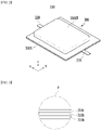
- Fig. 1 is an exploded perspective view illustrating a pouch type battery cell according to an embodiment of the present disclosure.
- Fig. 2 is a perspective view illustrating a state in which the pouch type battery cell of Fig. 1 is assembled.
- Fig. 3 is an enlarged cross-sectional view of the region P of Fig. 1 .
- the pouch type battery cell 100 can be manufactured by housing an electrode assembly 200 inside a cell case 300 and then sealing the cell case.
- the electrode assembly 200 may include a positive electrode, a negative electrode, and a separator disposed between the positive electrode and the negative electrode.
- the electrode assembly 200 may be a stack type electrode assembly, a jelly-roll type electrode assembly, or a stack/folding type electrode assembly.
- Each of the positive electrode and the negative electrode includes an electrode tab 210t, and the electrode leads 210 and 220 each connected to the electrode tab 210t may be exposed to the outside of the cell case 300.
- the electrode leads 210 and 220 can be located respectively in the sealing part 300S in a state of being covered with a lead film 400 so as to secure a sealing property and an insulation property.
- the cell case 300 is composed of a laminate sheet, and may include a resin layer for heat fusion and a metal layer for preventing material penetration.
- the cell case 300 may include an upper case 310 and a lower case 320.
- the upper case 310 may include an inside resin layer 310a for sealing, a metal layer 3 10b for preventing material penetration, and an outside resin layer 3 10c.
- the layer structure concerning the upper case 310 described above may be equally applied even to a lower case 320.
- the lower case 320 may include an inside resin layer, a metal layer and an outside resin layer along a direction away from the electrode assembly 200.
- the outside resin layer 310c and the packaging sheet layer can have excellent tensile strength and weather resistance compared to their thickness and have electrical insulation property in order to protect the pouch type secondary battery from the outside.
- the outside resin layer 310c may include a polyethylene terephthalate (PET) resin or a nylon resin.
- PET polyethylene terephthalate
- the metal layer 310b can prevent air, moisture and the like from flowing into the pouch type battery cell 100.
- the metal layer 310b may include aluminum (Al).
- the inside resin layer 310a can be heat-fused to each other by heat and pressure applied in a state where the electrode assembly 200 is built-in.
- the inside resin layer 310a may include casted polypropylene (CPP) or polypropylene (PP).
- a concave-shaped housing part 300ST on which the electrode assembly 200 can be seated may be formed in each of the upper case 310 and the lower case 320.
- the upper case 310 and the lower case 320 may be respectively provided with sealing parts 300S1 and 300S2 along the outer periphery of the housing part 300ST.
- the sealing part 300S1 of the upper case 310 and the sealing part 300S2 of the lower case 320 can be heat-fused to each other to form the sealing part 300S and seal the cell case 300.
- one side of the upper case and one side of the lower case can be integrally connected to each other, and the remaining three sides can be heat-fused.
- the plurality of positive electrodes and the plurality of negative electrodes included in the electrode assembly 200 may respectively include a positive electrode tab and a negative electrode tab, to which electrode leads 210 and 220 are connected.
- one of the electrode leads 210 and 220 may be a positive electrode lead, and the other may be a negative electrode lead.
- one of the electrode leads 210 and 220 connected to the electrode assembly 200 can protrude from one end part of the cell case 300 and be exposed to the outside of the cell case 300, and the other of the electrode leads 210 and 220 can protrude from the other one end part of the cell case 300 and be exposed to the outside of the cell case 300.
- the structure of the bidirectional electrode leads 210 and 220 has been described, but the electrode leads 210 and 220 can also be protruded in one direction.
- the corner part of the battery cell 100 may have a right-angled shape
- the corner part may have an inclined shape by pouch cell cutting described later.
- Figs. 4 and 5 are views illustrating a pouch cell cutting method according to a comparative example of the present disclosure.
- the side surface part of the battery cell may be folded after degassing during the pouch cell manufacturing process. Before folding the side surface part of the battery cell, the side surface part 350S and the corner part 350C of the battery cell can be cut. According to the comparative example, the side surface part 350S and the corner part 350C of the battery cell can be cut separately.
- the pouch cell cutting method according to the comparative example may include steps of positioning, corner cutting, 1st wing press, side cutting, and 2 nd wing press.
- the positioning step may be the step of properly fixing the position of the battery cell before cutting the battery cell
- the wing press step may be the step of pressing the sealing part of the battery cell with a heating plate.
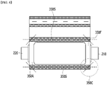
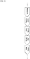
- Figs. 6 and 7 are views illustrating a pouch cell cutting method according to an embodiment of the present disclosure.
- the battery cell according to the present embodiment may be a pouch cell configured such that an electrode assembly is housed in a pouch type cell case.
- the pouch cell manufacturing method includes the steps of: housing an electrode assembly 200 in a cell case 300, injecting an electrolyte solution through a gas pocket part 100GP of the cell case 300, sealing the cell case 300 to form a sealing part 300S, and cutting the sealing part 300S.
- the step of cutting the sealing part 300S can simultaneously cut the corner part 350C and the side surface part 350S of the battery cell 100.
- the sealing part 300S to be cut may include a portion that connects the gas pocket part 100GP and the cell body part 100BP where the electrode assembly 200 is located.
- a cut part 300CP is formed in each of a side surface part 350S of which the battery cell 100 corresponding to the portion for connecting the gas pocket part 100GP and the cell body part 100BP and the side surface part 350S which is located on one side different from the side surface part 350S.
- the corner part 350C and the side surface part 350S of the battery cell 100 can be simultaneously cut in the cut part 300CP.
- the side surface part 350S of the battery cell 100 corresponds to a portion extending in the longitudinal direction of the battery cell 100, and the electrode leads 210 and 220 protruding from the battery cell 100 may be protruded in the longitudinal direction of the battery cell 100.
- the first electrode lead 210 is protruded from the front surface part 350F of the battery cell 100
- the second electrode lead 220 may be protruded from the rear surface part 350R of the battery cell 100.
- the side surface part 350S of the battery cell 100 is a portion connecting the front surface part 350F and the rear surface part 350R of the battery cell 100, and can correspond to the edge extending along the longitudinal direction of the battery cell 100.
- the pouch cell cutting method may include steps of positioning, simultaneous cutting for corner and side, and wing press.
- the positioning step may be the step of properly fixing the position of the battery cell before cutting the battery cell
- the wing press step may be the step of pressing the sealing part of the battery cell with a heating plate.
- the corner part 350C and the side surface part 350S of the battery cell 100 are simultaneously cut, so that the corner part 350C of the battery cell 100 can form an inclination angle with respect to the side surface part 350S of the battery cell 100.
- a spiral roller or the like is used to make the sealing part 300S into a double side folded shape in a subsequent step, wherein it is possible to prevent in advance the problem that the battery cell 100 corresponding to the corner part 350C is sagging.
- the double side folded shape may be a shape formed by folding the sealing part of the cell case at least twice.
- Fig. 8 is a view illustrating a pouch cell cutting apparatus according to another embodiment of the present disclosure.
- the pouch cell cutting apparatus comprises a top knife 500 and a bottom knife 600 for cutting a sealing part 300S of a battery cell 100 which includes a cell case and an electrode assembly housed in the cell case, wherein both side parts of the top knife 500 comprises protrusion parts 500P protruding toward recessed parts 600D formed on both side parts of the bottom knife 600, respectively. Wherein, a corner part 350C of the battery cell 100 is cut by the protrusion part 500P.
- the length of the top knife may be shorter than the length of the bottom knife.
- a boundary part between the top knife 500 and the bottom knife 600 corresponds to the sealing part 300S of the battery cell 100, and a cut part of the battery cell 100 may be formed at the boundary part.
- a corner part 350C and a side surface part 350S of the battery cell 100 may be simultaneously cut in the cutting part.
- a shear angle is formed in the top knife 500 by the protrusion part 500P, and the corner part 350C of the battery cell 100 may be cut so as to correspond to the shear angle.
- pouch type battery cells according to an embodiment of the present disclosure can be gathered to constitute a battery module, and one or more battery modules can be packaged in a pack case to form a battery pack.
- the above-mentioned battery module and battery pack can be applied to various devices.
- a device may be applied to a vehicle means such as an electric bicycle, an electric vehicle, or a hybrid vehicle, but the present disclosure is not limited thereto, and is applicable to various devices that can use a battery module, which also belongs to the scope of the present disclosure.
Landscapes
- Chemical & Material Sciences (AREA)
- Chemical Kinetics & Catalysis (AREA)
- Electrochemistry (AREA)
- General Chemical & Material Sciences (AREA)
- Engineering & Computer Science (AREA)
- Life Sciences & Earth Sciences (AREA)
- Forests & Forestry (AREA)
- Mechanical Engineering (AREA)
- Manufacturing & Machinery (AREA)
- Sealing Battery Cases Or Jackets (AREA)
Abstract
Description
- This application claims the benefit of
Korean Patent Application No. 10-2020-0151199 filed on November 12, 2020 - The present disclosure relates to a pouch cell cutting apparatus and a pouch cell manufacturing method, and more particularly, to a pouch cell cutting apparatus and a pouch cell manufacturing method in which the process has been simplified.
- Recently, as energy source price is increasing due to the depletion of fossil fuels and increasing interest is being paid to environmental pollution, the demand for environmentally-friendly alternative energy sources is bound to play an important role in the future life. Thus, research into techniques for generating various kinds of power, such as nuclear energy, solar energy, wind energy, and tidal power, is underway, and power storage apparatuses for more efficient use of the generated energy are also drawing much attention.
- In particular, as technology development and demands for mobile devices increase, the demand for batteries as energy sources is rapidly increasing. Accordingly, many researches on batteries capable of meeting diverse demands have been conducted.
- Typically, the demand for the lithium secondary battery, such as a lithium ion battery or a lithium ion polymer battery, which have advantages such as a high energy density, a discharge voltage, an output stability, and the like is high.
- Based on the shape of a battery case, such a secondary battery is classified into a cylindrical battery where an electrode assembly is built into a cylindrical metal can, a prismatic battery where an electrode assembly is built into a prismatic metal can, and a pouch type battery where an electrode assembly is built into a cell case of an aluminum laminate sheet.
- In a pouch type secondary battery, a high temperature environment and a large amount of gas generated during a long-term cycle test may cause a vent in the sealing part of the cell case and the electrode lead. For this reason, the safety problem of a secondary battery is emerging. In order to reduce this safety problem, it is necessary to improve the sealing quality of the cell case and the electrode lead.
- It is an object of the present disclosure to provide a pouch cell cutting apparatus and a pouch cell manufacturing method in which the process has been simplified.
- However, the technical problem to be solved by embodiments of the present disclosure is not limited to the above-described problems, and can be variously expanded within the scope of the technical idea included in the present disclosure.
- According to an embodiment of the present disclosure, there is provided a pouch cell cutting apparatus, comprising: a top knife and a bottom knife for cutting a sealing part of a battery cell which includes a cell case and an electrode assembly housed in the cell case, wherein both side parts of the top knife comprise protrusion parts protruding toward recessed parts formed on both side parts of the bottom knife, respectively, and wherein a corner part of the battery cell is cut by the protrusion part.
- A boundary part between the top knife and the bottom knife corresponds to the sealing part of the battery cell, and a cut part of the battery cell is formed at the boundary part, and the corner part and a side surface part of the battery cell may be simultaneously cut in the cutting part.
- A shear angle may be formed in the top knife by the protrusion part, and the corner part of the battery cell may be cut so as to correspond to the shear angle.
- The side surface part of the battery cell corresponds to a portion extending in the longitudinal direction of the battery cell, and an electrode lead protruding from the battery cell may be protruded in the longitudinal direction of the battery cell.
- The battery cell comprises a cell body part where the electrode assembly is located and a gas pocket part connected to the cell body part, and the cut part may comprise a portion where the cell body part and the gas pocket part are connected.
- According to another embodiment of the present disclosure, there is provided a pouch cell manufacturing method, comprising the steps of: housing an electrode assembly in a cell case, injecting an electrolyte solution through a gas pocket part of the cell case, sealing the cell case to form a sealing part, and cutting the sealing part, wherein the step of cutting the sealing part simultaneously cut a corner part and a side surface part of a battery cell.
- The pouch cell manufacturing method may further comprise fixing the position of the battery cell, before the step of cutting the sealing part.
- The side surface part of the battery cell corresponds to a portion extending in the longitudinal direction of the battery cell, and an electrode lead protruding from the battery cell may be protruded in the longitudinal direction of the battery cell.
- The sealing part may comprise a portion that connects the gas pocket part and a cell body part where the electrode assembly is located.
- The corner part and the side surface part of the battery cell are simultaneously cut, so that the corner part of the battery cell may form an inclination angle with respect to the side surface part of the battery cell.
- According to embodiments of the present disclosure, before side-folding the cell after degassing, the cell, the corner part and the side surface part are cut at the same time without cutting separately, whereby the process can be simplified and the danger of generating scrap or breaking the insulation can be reduced.
- The effects of the present disclosure are not limited to the effects mentioned above and additional other effects not described above will be clearly understood from the description of the appended claims by those skilled in the art.
-
-
Fig. 1 is an exploded perspective view illustrating a pouch type battery cell according to an embodiment of the present disclosure; -
Fig. 2 is a perspective view illustrating a state in which the pouch type battery cell ofFig. 1 is assembled; -
Fig. 3 is an enlarged cross-sectional view of the region P ofFig. 1 ; -
Figs. 4 and5 are views illustrating a pouch cell cutting method according to a comparative example of the present disclosure; -
Figs. 6 and7 are views illustrating a pouch cell cutting method according to an embodiment of the present disclosure; and -
Fig. 8 is a view illustrating a pouch cell cutting apparatus according to another embodiment of the present disclosure. - Hereinafter, various embodiments of the present disclosure will be described in detail with reference to the accompanying drawings so that those skilled in the art can easily carry out them. The present disclosure may be modified in various different ways, and is not limited to the embodiments set forth herein.
- A description of parts not related to the description will be omitted herein for clarity, and like reference numerals designate like elements throughout the description.
- Further, in the drawings, the size and thickness of each element are arbitrarily illustrated for convenience of description, and the present disclosure is not necessarily limited to those illustrated in the drawings. In the drawings, the thickness of layers, regions, etc. are exaggerated for clarity. In the drawings, for convenience of description, the thicknesses of some layers and regions are exaggerated.
- In addition, it will be understood that when an element such as a layer, film, region, or plate is referred to as being "on" or "above" another element, it can be directly on the other element or intervening elements may also be present. In contrast, when an element is referred to as being "directly on" another element, it means that other intervening elements are not present. Further, the word "on" or "above" means disposed on or below a reference portion, and does not necessarily mean being disposed on the upper end of the reference portion toward the opposite direction of gravity.
- Further, throughout the description, when a portion is referred to as "including" a certain component, it means that the portion can further include other components, without excluding the other components, unless otherwise stated.
- Further, throughout the description, when referred to as "planar", it means when a target portion is viewed from the upper side, and when referred to as "cross-sectional", it means when a target portion is viewed from the side of a cross section cut vertically.
-
Fig. 1 is an exploded perspective view illustrating a pouch type battery cell according to an embodiment of the present disclosure.Fig. 2 is a perspective view illustrating a state in which the pouch type battery cell ofFig. 1 is assembled.Fig. 3 is an enlarged cross-sectional view of the region P ofFig. 1 . - Referring to
Figs. 1 and2 , the pouchtype battery cell 100 according to the present embodiment can be manufactured by housing anelectrode assembly 200 inside acell case 300 and then sealing the cell case. Theelectrode assembly 200 may include a positive electrode, a negative electrode, and a separator disposed between the positive electrode and the negative electrode. Theelectrode assembly 200 may be a stack type electrode assembly, a jelly-roll type electrode assembly, or a stack/folding type electrode assembly. - Each of the positive electrode and the negative electrode includes an
electrode tab 210t, and the electrode leads 210 and 220 each connected to theelectrode tab 210t may be exposed to the outside of thecell case 300. In addition, the electrode leads 210 and 220 can be located respectively in the sealingpart 300S in a state of being covered with alead film 400 so as to secure a sealing property and an insulation property. - The
cell case 300 is composed of a laminate sheet, and may include a resin layer for heat fusion and a metal layer for preventing material penetration. Thecell case 300 may include anupper case 310 and alower case 320. - Specifically, referring to
Fig. 3 , theupper case 310 may include aninside resin layer 310a for sealing, a metal layer 3 10b for preventing material penetration, and an outside resin layer 3 10c. - The layer structure concerning the
upper case 310 described above may be equally applied even to alower case 320. In other words, thelower case 320 may include an inside resin layer, a metal layer and an outside resin layer along a direction away from theelectrode assembly 200. - The
outside resin layer 310c and the packaging sheet layer can have excellent tensile strength and weather resistance compared to their thickness and have electrical insulation property in order to protect the pouch type secondary battery from the outside. Theoutside resin layer 310c may include a polyethylene terephthalate (PET) resin or a nylon resin. The metal layer 310b can prevent air, moisture and the like from flowing into the pouchtype battery cell 100. The metal layer 310b may include aluminum (Al). Theinside resin layer 310a can be heat-fused to each other by heat and pressure applied in a state where theelectrode assembly 200 is built-in. Theinside resin layer 310a may include casted polypropylene (CPP) or polypropylene (PP). - Referring back to
Figs. 1 and2 , a concave-shaped housing part 300ST on which theelectrode assembly 200 can be seated may be formed in each of theupper case 310 and thelower case 320. Theupper case 310 and thelower case 320 may be respectively provided with sealing parts 300S1 and 300S2 along the outer periphery of the housing part 300ST. The sealing part 300S1 of theupper case 310 and the sealing part 300S2 of thelower case 320 can be heat-fused to each other to form the sealingpart 300S and seal thecell case 300. - In another embodiment of the present disclosure, one side of the upper case and one side of the lower case can be integrally connected to each other, and the remaining three sides can be heat-fused.
- Meanwhile, the plurality of positive electrodes and the plurality of negative electrodes included in the
electrode assembly 200 may respectively include a positive electrode tab and a negative electrode tab, to which electrode leads 210 and 220 are connected. Specifically, one of the electrode leads 210 and 220 may be a positive electrode lead, and the other may be a negative electrode lead. As described above, one of the electrode leads 210 and 220 connected to theelectrode assembly 200 can protrude from one end part of thecell case 300 and be exposed to the outside of thecell case 300, and the other of the electrode leads 210 and 220 can protrude from the other one end part of thecell case 300 and be exposed to the outside of thecell case 300. In the present embodiment, the structure of the bidirectional electrode leads 210 and 220 has been described, but the electrode leads 210 and 220 can also be protruded in one direction. - Although it is illustrated in
Fig. 2 that the corner part of thebattery cell 100 have a right-angled shape, the corner part may have an inclined shape by pouch cell cutting described later. -
Figs. 4 and5 are views illustrating a pouch cell cutting method according to a comparative example of the present disclosure. - Referring to
Fig. 4 , in the pouch cell cutting method according to the comparative example, the side surface part of the battery cell may be folded after degassing during the pouch cell manufacturing process. Before folding the side surface part of the battery cell, theside surface part 350S and thecorner part 350C of the battery cell can be cut. According to the comparative example, theside surface part 350S and thecorner part 350C of the battery cell can be cut separately. - When the
side surface part 350S and thecorner part 350C of the battery cell are separately cut in this way, there is a risk that uncut scrap remains when cutting thecorner part 350C. In order to prevent wrinkles and warpage on the cut surface immediately after cutting, there is a troublesome that the wing press step must be performed. Specifically, when thecorner part 350C is cut separately, the size of thecut corner part 350C itself is very small, so that the scrap may be very small and the danger of leakage may be higher. - Specifically, referring to
Fig. 5 , the pouch cell cutting method according to the comparative example may include steps of positioning, corner cutting, 1st wing press, side cutting, and 2nd wing press. Here, the positioning step may be the step of properly fixing the position of the battery cell before cutting the battery cell, and the wing press step may be the step of pressing the sealing part of the battery cell with a heating plate. - According to the comparative example, since a large number of wing press steps are performed, there is a risk that the insulation of the edge part of the sealing part is broken.
-
Figs. 6 and7 are views illustrating a pouch cell cutting method according to an embodiment of the present disclosure. - Referring to
Fig. 6 , the battery cell according to the present embodiment may be a pouch cell configured such that an electrode assembly is housed in a pouch type cell case. - Referring to
Figs. 1 ,2 and6 , the pouch cell manufacturing method according to the present embodiment includes the steps of: housing anelectrode assembly 200 in acell case 300, injecting an electrolyte solution through a gas pocket part 100GP of thecell case 300, sealing thecell case 300 to form asealing part 300S, and cutting the sealingpart 300S. Wherein, the step of cutting the sealingpart 300S can simultaneously cut thecorner part 350C and theside surface part 350S of thebattery cell 100. - The sealing
part 300S to be cut according to the present embodiment may include a portion that connects the gas pocket part 100GP and the cell body part 100BP where theelectrode assembly 200 is located. A cut part 300CP is formed in each of aside surface part 350S of which thebattery cell 100 corresponding to the portion for connecting the gas pocket part 100GP and the cell body part 100BP and theside surface part 350S which is located on one side different from theside surface part 350S. Thecorner part 350C and theside surface part 350S of thebattery cell 100 can be simultaneously cut in the cut part 300CP. - The
side surface part 350S of thebattery cell 100 according to the present embodiment corresponds to a portion extending in the longitudinal direction of thebattery cell 100, and the electrode leads 210 and 220 protruding from thebattery cell 100 may be protruded in the longitudinal direction of thebattery cell 100. Specifically, thefirst electrode lead 210 is protruded from thefront surface part 350F of thebattery cell 100, and thesecond electrode lead 220 may be protruded from therear surface part 350R of thebattery cell 100. Theside surface part 350S of thebattery cell 100 is a portion connecting thefront surface part 350F and therear surface part 350R of thebattery cell 100, and can correspond to the edge extending along the longitudinal direction of thebattery cell 100. - When the
side surface part 350S and thecorner part 350C of the battery cell are simultaneously cut in this way, it is possible to minimize the risk that uncut scrap remains when cutting thecorner part 350C. It is not necessary to add a wing press step between the corner cutting step and the side cutting step in order to prevent wrinkles and warpage on the cut surface, and thus, the process can be simplified. - Specifically, referring to
Fig. 7 , the pouch cell cutting method according to the present embodiment may include steps of positioning, simultaneous cutting for corner and side, and wing press. Here, the positioning step may be the step of properly fixing the position of the battery cell before cutting the battery cell, and the wing press step may be the step of pressing the sealing part of the battery cell with a heating plate. - According to the present embodiment, since the number of wing press steps is minimized, it is possible to reduce the risk of breaking the insulation at the edge part of the sealing part.
- According to the present embodiment, the
corner part 350C and theside surface part 350S of thebattery cell 100 are simultaneously cut, so that thecorner part 350C of thebattery cell 100 can form an inclination angle with respect to theside surface part 350S of thebattery cell 100. - By cutting the
corner part 350C according to the present embodiment, a spiral roller or the like is used to make the sealingpart 300S into a double side folded shape in a subsequent step, wherein it is possible to prevent in advance the problem that thebattery cell 100 corresponding to thecorner part 350C is sagging. The double side folded shape may be a shape formed by folding the sealing part of the cell case at least twice. - Further, by cutting the
side surface part 350S according to the present embodiment, it is possible to control the standard for forming the double side folded sealing part. -
Fig. 8 is a view illustrating a pouch cell cutting apparatus according to another embodiment of the present disclosure. - Referring to
Fig. 8 , the pouch cell cutting apparatus according to the present embodiment comprises atop knife 500 and abottom knife 600 for cutting a sealingpart 300S of abattery cell 100 which includes a cell case and an electrode assembly housed in the cell case, wherein both side parts of thetop knife 500 comprisesprotrusion parts 500P protruding toward recessedparts 600D formed on both side parts of thebottom knife 600, respectively. Wherein, acorner part 350C of thebattery cell 100 is cut by theprotrusion part 500P. The length of the top knife may be shorter than the length of the bottom knife. - A boundary part between the
top knife 500 and thebottom knife 600 corresponds to the sealingpart 300S of thebattery cell 100, and a cut part of thebattery cell 100 may be formed at the boundary part. Acorner part 350C and aside surface part 350S of thebattery cell 100 may be simultaneously cut in the cutting part. - A shear angle is formed in the
top knife 500 by theprotrusion part 500P, and thecorner part 350C of thebattery cell 100 may be cut so as to correspond to the shear angle. - Meanwhile, several pouch type battery cells according to an embodiment of the present disclosure can be gathered to constitute a battery module, and one or more battery modules can be packaged in a pack case to form a battery pack.
- The above-mentioned battery module and battery pack can be applied to various devices. Such a device may be applied to a vehicle means such as an electric bicycle, an electric vehicle, or a hybrid vehicle, but the present disclosure is not limited thereto, and is applicable to various devices that can use a battery module, which also belongs to the scope of the present disclosure.
- Although the invention has been shown and described above with reference to the preferred embodiments, the scope of the present disclosure is not limited thereto, and numerous other variations and modifications can be devised by those skilled in the art using the principles of the invention described in the appended claims, which will also fall within the spirit and scope of the present disclosure.
-
- 100: battery cell
- 100BP: cell body part
- 100GP: gas pocket part
- 300: cell case
- 300S: sealing part
- 300CP: cut part
- 350C: corner part
- 350S: side surface part
- 500: top knife
- 500P: protrusion part
- 600: bottom knife
Claims (10)
- A pouch cell cutting apparatus, comprising:a top knife and a bottom knife for cutting a sealing part of a battery cell which includes a cell case and an electrode assembly housed in the cell case,wherein both side parts of the top knife comprise protrusion parts protruding toward recessed parts formed on both side parts of the bottom knife, respectively, andwherein a corner part of the battery cell is cut by the protrusion part.
- The pouch cell cutting apparatus according to claim 1, wherein:a boundary part between the top knife and the bottom knife corresponds to the sealing part of the battery cell, and a cut part of the battery cell is formed at the boundary part, andthe corner part and a side surface part of the battery cell are simultaneously cut in the cutting part.
- The pouch cell cutting apparatus according to claim 2, wherein:
a shear angle is formed in the top knife by the protrusion part, and the corner part of the battery cell is cut so as to correspond to the shear angle. - The pouch cell cutting apparatus according to claim 2, wherein:
the side surface part of the battery cell corresponds to a portion extending in the longitudinal direction of the battery cell, and an electrode lead protruding from the battery cell is protruded in the longitudinal direction of the battery cell. - The pouch cell cutting apparatus according to claim 2, wherein:the battery cell comprises a cell body part where the electrode assembly is located and a gas pocket part connected to the cell body part, andthe cut part comprises a portion where the cell body part and the gas pocket part are connected.
- A pouch cell manufacturing method, comprising the steps of:housing an electrode assembly in a cell case,injecting an electrolyte solution through a gas pocket part of the cell case,sealing the cell case to form a sealing part, andcutting the sealing part,wherein the step of cutting the sealing part simultaneously cuts a corner part and a side surface part of a battery cell.
- The pouch cell manufacturing method according to claim 6, which further comprises fixing the position of the battery cell, before the step of cutting the sealing part.
- The pouch cell manufacturing method according to claim 6, wherein:
the side surface part of the battery cell corresponds to a portion extending in the longitudinal direction of the battery cell, and an electrode lead protruding from the battery cell is protruded in the longitudinal direction of the battery cell. - The pouch cell manufacturing method according to claim 6, wherein:
the sealing part comprises a portion that connects the gas pocket part and a cell body part where the electrode assembly is located. - The pouch cell manufacturing method according to claim 6, wherein:
the corner part and the side surface part of the battery cell are simultaneously cut, so that the corner part of the battery cell forms an inclination angle with respect to the side surface part of the battery cell.
Applications Claiming Priority (2)
| Application Number | Priority Date | Filing Date | Title |
|---|---|---|---|
| KR1020200151199A KR20220064751A (en) | 2020-11-12 | 2020-11-12 | Pouch cell cutting apparatus and pouch cell manufacturing method |
| PCT/KR2021/014437 WO2022102998A1 (en) | 2020-11-12 | 2021-10-18 | Pouch cell cutting apparatus and pouch cell manufacturing method |
Publications (2)
| Publication Number | Publication Date |
|---|---|
| EP4123797A1 true EP4123797A1 (en) | 2023-01-25 |
| EP4123797A4 EP4123797A4 (en) | 2024-07-17 |
Family
ID=81601384
Family Applications (1)
| Application Number | Title | Priority Date | Filing Date |
|---|---|---|---|
| EP21892168.2A Pending EP4123797A4 (en) | 2020-11-12 | 2021-10-18 | Pouch cell cutting apparatus and pouch cell manufacturing method |
Country Status (5)
| Country | Link |
|---|---|
| US (1) | US20230163379A1 (en) |
| EP (1) | EP4123797A4 (en) |
| KR (1) | KR20220064751A (en) |
| CN (1) | CN115298883B (en) |
| WO (1) | WO2022102998A1 (en) |
Families Citing this family (1)
| Publication number | Priority date | Publication date | Assignee | Title |
|---|---|---|---|---|
| KR102682620B1 (en) | 2024-01-12 | 2024-07-08 | 주식회사 지에스아이 | Apparatus for cutting a sheet |
Family Cites Families (13)
| Publication number | Priority date | Publication date | Assignee | Title |
|---|---|---|---|---|
| CN202678421U (en) * | 2012-05-23 | 2013-01-16 | 宁德新能源科技有限公司 | Flexibly packaged polymer lithium ion battery |
| KR20140036437A (en) * | 2012-09-14 | 2014-03-26 | 주식회사 엘지화학 | Fabricating method of secondary battery and electrochemical cell having the secondary battery |
| KR102236347B1 (en) * | 2014-08-29 | 2021-04-05 | 에스케이이노베이션 주식회사 | Method for Manufacturing Secondary Battery |
| KR101726783B1 (en) * | 2014-11-06 | 2017-04-13 | 주식회사 엘지화학 | Process of Manufacturing Battery Cell Including Formation Step of Auxiliary Sealing Part |
| CN104852014B (en) * | 2015-05-14 | 2017-10-20 | 宁德时代新能源科技股份有限公司 | Device for preparing lithium ion battery pole piece element |
| CN204538120U (en) * | 2015-05-14 | 2015-08-05 | 宁德时代新能源科技有限公司 | A kind of device preparing electrodes of lithium-ion batteries element |
| CN205646005U (en) * | 2016-02-01 | 2016-10-12 | 东莞新能源科技有限公司 | Flexible package lithium ion battery |
| KR102066909B1 (en) * | 2016-10-04 | 2020-01-16 | 주식회사 엘지화학 | Electrode Lead Machining Apparatus Capable of Forming Round Shape at Electrode Lead and Battery Cell Comprising Machined Electrode Lead by Using the Same |
| KR101937936B1 (en) * | 2017-06-08 | 2019-01-11 | (주)광신하이테크 | Battery pouch film forming cutting device and foaming cutting method |
| KR102394495B1 (en) * | 2017-11-14 | 2022-05-04 | 주식회사 엘지에너지솔루션 | The Pouch For Secondary Battery, The Secondary Battery And The Method For Manufacturing Thereof |
| KR101908586B1 (en) * | 2018-07-16 | 2018-10-16 | 주식회사 셀텍 | Automatic cutting edge of terrace edge of secondary battery cell |
| CN209312886U (en) * | 2018-12-27 | 2019-08-27 | 湖南泰和美新能源科技有限公司 | A kind of soft package lithium battery negative electrode lug cutter assembly and the pelleter with the component |
| CN210282566U (en) * | 2019-05-22 | 2020-04-10 | 江西坤阳新能源有限公司 | Lithium battery edge cutting device |
-
2020
- 2020-11-12 KR KR1020200151199A patent/KR20220064751A/en active Search and Examination
-
2021
- 2021-10-18 EP EP21892168.2A patent/EP4123797A4/en active Pending
- 2021-10-18 WO PCT/KR2021/014437 patent/WO2022102998A1/en unknown
- 2021-10-18 CN CN202180022705.1A patent/CN115298883B/en active Active
- 2021-10-18 US US17/919,690 patent/US20230163379A1/en active Pending
Also Published As
| Publication number | Publication date |
|---|---|
| WO2022102998A1 (en) | 2022-05-19 |
| CN115298883A (en) | 2022-11-04 |
| CN115298883B (en) | 2024-08-20 |
| US20230163379A1 (en) | 2023-05-25 |
| KR20220064751A (en) | 2022-05-19 |
| EP4123797A4 (en) | 2024-07-17 |
Similar Documents
| Publication | Publication Date | Title |
|---|---|---|
| US20210066676A1 (en) | Pouch exterior for secondary battery, pouch-type secondary battery using the pouch exterior, and method of manufacturing the pouch-type secondary battery | |
| CN106067525B (en) | Secondary battery and battery module having the same | |
| KR101244549B1 (en) | Rectangular battery | |
| EP4064427A1 (en) | Pouch type secondary battery and battery module including same | |
| EP3561902A1 (en) | Battery module, battery pack comprising battery module, and vehicle comprising battery pack | |
| CN106463665A (en) | Battery cell assembly for secondary battery, and secondary battery comprising same | |
| JP2010186786A (en) | Electrical storage device and electrical storage device module | |
| EP4123797A1 (en) | Pouch cell cutting apparatus and pouch cell manufacturing method | |
| EP4142040A1 (en) | Secondary battery and device including same | |
| KR101441645B1 (en) | Pouch film for secondary battery and method for manufacturing secondary battery using the same | |
| US11855296B2 (en) | Battery cell having battery casing with receiving part and electrode lead groove | |
| EP4148877A1 (en) | Method for adhering of tape for secondary battery | |
| EP4224621A1 (en) | Secondary battery and device comprising same | |
| EP4148878A1 (en) | Apparatus for adhering tape for secondary battery and adhering method using same | |
| EP4040582A1 (en) | Battery module and battery pack including same | |
| KR20220041425A (en) | Battery cell and battery module including the same | |
| KR20170117674A (en) | Battery Cell Comprising Electrode Lead Coated with Thin Film Layer for Sealing | |
| KR20210009184A (en) | Battery module and method of manufacturing the same | |
| CN219457681U (en) | Secondary battery | |
| EP4224622A1 (en) | Secondary battery and method for manufacturing same | |
| EP4056352A1 (en) | Apparatus of manufacturing pouch type battery | |
| EP4092793A1 (en) | Battery cell and method for manufacturing same | |
| US20220263204A1 (en) | Battery Cell, Battery Module And Vehicle | |
| KR20230148581A (en) | Battery cell manufacturing device | |
| KR20220046481A (en) | Pouch type secondary battery and manufacturing method of the same |
Legal Events
| Date | Code | Title | Description |
|---|---|---|---|
| STAA | Information on the status of an ep patent application or granted ep patent |
Free format text: STATUS: THE INTERNATIONAL PUBLICATION HAS BEEN MADE |
|
| PUAI | Public reference made under article 153(3) epc to a published international application that has entered the european phase |
Free format text: ORIGINAL CODE: 0009012 |
|
| STAA | Information on the status of an ep patent application or granted ep patent |
Free format text: STATUS: REQUEST FOR EXAMINATION WAS MADE |
|
| 17P | Request for examination filed |
Effective date: 20221019 |
|
| AK | Designated contracting states |
Kind code of ref document: A1 Designated state(s): AL AT BE BG CH CY CZ DE DK EE ES FI FR GB GR HR HU IE IS IT LI LT LU LV MC MK MT NL NO PL PT RO RS SE SI SK SM TR |
|
| DAV | Request for validation of the european patent (deleted) | ||
| DAX | Request for extension of the european patent (deleted) | ||
| A4 | Supplementary search report drawn up and despatched |
Effective date: 20240619 |
|
| RIC1 | Information provided on ipc code assigned before grant |
Ipc: H01M 50/105 20210101ALI20240613BHEP Ipc: B26F 1/40 20060101ALI20240613BHEP Ipc: H01M 10/04 20060101ALI20240613BHEP Ipc: B26F 1/44 20060101ALI20240613BHEP Ipc: H01M 50/30 20210101ALI20240613BHEP Ipc: H01M 50/116 20210101AFI20240613BHEP |