EP4123788A1 - Internal resistance calculation device, battery control system, and internal resistance calculation method - Google Patents
Internal resistance calculation device, battery control system, and internal resistance calculation method Download PDFInfo
- Publication number
- EP4123788A1 EP4123788A1 EP21771830.3A EP21771830A EP4123788A1 EP 4123788 A1 EP4123788 A1 EP 4123788A1 EP 21771830 A EP21771830 A EP 21771830A EP 4123788 A1 EP4123788 A1 EP 4123788A1
- Authority
- EP
- European Patent Office
- Prior art keywords
- battery
- internal resistance
- amount
- charge
- current
- Prior art date
- Legal status (The legal status is an assumption and is not a legal conclusion. Google has not performed a legal analysis and makes no representation as to the accuracy of the status listed.)
- Pending
Links
Images


Classifications
-
- H—ELECTRICITY
- H01—ELECTRIC ELEMENTS
- H01M—PROCESSES OR MEANS, e.g. BATTERIES, FOR THE DIRECT CONVERSION OF CHEMICAL ENERGY INTO ELECTRICAL ENERGY
- H01M10/00—Secondary cells; Manufacture thereof
- H01M10/42—Methods or arrangements for servicing or maintenance of secondary cells or secondary half-cells
- H01M10/48—Accumulators combined with arrangements for measuring, testing or indicating the condition of cells, e.g. the level or density of the electrolyte
-
- G—PHYSICS
- G01—MEASURING; TESTING
- G01R—MEASURING ELECTRIC VARIABLES; MEASURING MAGNETIC VARIABLES
- G01R31/00—Arrangements for testing electric properties; Arrangements for locating electric faults; Arrangements for electrical testing characterised by what is being tested not provided for elsewhere
- G01R31/36—Arrangements for testing, measuring or monitoring the electrical condition of accumulators or electric batteries, e.g. capacity or state of charge [SoC]
- G01R31/374—Arrangements for testing, measuring or monitoring the electrical condition of accumulators or electric batteries, e.g. capacity or state of charge [SoC] with means for correcting the measurement for temperature or ageing
-
- G—PHYSICS
- G01—MEASURING; TESTING
- G01R—MEASURING ELECTRIC VARIABLES; MEASURING MAGNETIC VARIABLES
- G01R31/00—Arrangements for testing electric properties; Arrangements for locating electric faults; Arrangements for electrical testing characterised by what is being tested not provided for elsewhere
- G01R31/36—Arrangements for testing, measuring or monitoring the electrical condition of accumulators or electric batteries, e.g. capacity or state of charge [SoC]
- G01R31/382—Arrangements for monitoring battery or accumulator variables, e.g. SoC
- G01R31/3842—Arrangements for monitoring battery or accumulator variables, e.g. SoC combining voltage and current measurements
-
- G—PHYSICS
- G01—MEASURING; TESTING
- G01R—MEASURING ELECTRIC VARIABLES; MEASURING MAGNETIC VARIABLES
- G01R31/00—Arrangements for testing electric properties; Arrangements for locating electric faults; Arrangements for electrical testing characterised by what is being tested not provided for elsewhere
- G01R31/36—Arrangements for testing, measuring or monitoring the electrical condition of accumulators or electric batteries, e.g. capacity or state of charge [SoC]
- G01R31/389—Measuring internal impedance, internal conductance or related variables
-
- G—PHYSICS
- G01—MEASURING; TESTING
- G01R—MEASURING ELECTRIC VARIABLES; MEASURING MAGNETIC VARIABLES
- G01R31/00—Arrangements for testing electric properties; Arrangements for locating electric faults; Arrangements for electrical testing characterised by what is being tested not provided for elsewhere
- G01R31/36—Arrangements for testing, measuring or monitoring the electrical condition of accumulators or electric batteries, e.g. capacity or state of charge [SoC]
- G01R31/392—Determining battery ageing or deterioration, e.g. state of health
-
- H—ELECTRICITY
- H02—GENERATION; CONVERSION OR DISTRIBUTION OF ELECTRIC POWER
- H02J—ELECTRIC POWER NETWORKS; CIRCUIT ARRANGEMENTS OR SYSTEMS FOR SUPPLYING OR DISTRIBUTING ELECTRIC POWER; SYSTEMS FOR STORING ELECTRIC ENERGY
- H02J7/00—Circuit arrangements for charging or discharging batteries or for supplying loads from batteries
- H02J7/80—Circuit arrangements for charging or discharging batteries or for supplying loads from batteries including monitoring or indicating arrangements
-
- H—ELECTRICITY
- H02—GENERATION; CONVERSION OR DISTRIBUTION OF ELECTRIC POWER
- H02J—ELECTRIC POWER NETWORKS; CIRCUIT ARRANGEMENTS OR SYSTEMS FOR SUPPLYING OR DISTRIBUTING ELECTRIC POWER; SYSTEMS FOR STORING ELECTRIC ENERGY
- H02J7/00—Circuit arrangements for charging or discharging batteries or for supplying loads from batteries
- H02J7/80—Circuit arrangements for charging or discharging batteries or for supplying loads from batteries including monitoring or indicating arrangements
- H02J7/84—Control of state of health [SOH]
-
- Y—GENERAL TAGGING OF NEW TECHNOLOGICAL DEVELOPMENTS; GENERAL TAGGING OF CROSS-SECTIONAL TECHNOLOGIES SPANNING OVER SEVERAL SECTIONS OF THE IPC; TECHNICAL SUBJECTS COVERED BY FORMER USPC CROSS-REFERENCE ART COLLECTIONS [XRACs] AND DIGESTS
- Y02—TECHNOLOGIES OR APPLICATIONS FOR MITIGATION OR ADAPTATION AGAINST CLIMATE CHANGE
- Y02E—REDUCTION OF GREENHOUSE GAS [GHG] EMISSIONS, RELATED TO ENERGY GENERATION, TRANSMISSION OR DISTRIBUTION
- Y02E60/00—Enabling technologies; Technologies with a potential or indirect contribution to GHG emissions mitigation
- Y02E60/10—Energy storage using batteries
Definitions
- Embodiments of the present invention relate to an internal resistance calculation device, a battery control system, and an internal resistance calculation method.
- a technique has been developed to perform measurement of a battery voltage on a no-load battery 10 seconds after the start of passing a square wave rated current (pulse current) with a four-level pulse current and to calculate, as internal resistance, the absolute value of the slope of an approximate line formed by the pulse current at each level and the battery voltage measured at each level. That is, the internal resistance of a battery is calculated on the basis of the amount of variation in current, which is an amount of variation in the pulse current flowing through the battery, and the amount of variation in voltage, which is an amount of variation in the battery voltage measured at each level.
- the above-described technique assumes testing using a DC power supply independently controllable for each battery, and the condition is that the current flowing through the battery is a pulse current. Therefore, if the current flowing through the battery is other than the pulse current, it is difficult to calculate the internal resistance of the battery with high precision.
- An internal resistance calculation device of an embodiment includes a current acquisition unit, a voltage acquisition unit, a charge amount calculation unit, and an internal resistance calculation unit.
- the current acquisition unit is configured to acquire a battery current flowing through a battery.
- the voltage acquisition unit is configured to acquire a battery voltage applied to the battery.
- the charge amount calculation unit configured to calculate an amount of charge that has moved to the battery. The amount of charge is calculated by integrating the battery current acquired by the current acquisition unit over time.
- the internal resistance calculation unit is configured to calculate internal resistance of the battery on the basis of an amount of variation in the battery current and an amount of variation in the battery voltage, each being obtained until the amount of charge calculated by the charge amount calculation unit becomes equal to or greater than a preset threshold.
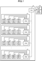
- FIG. 1 is a diagram illustrating an example of a configuration of a battery control system according to a first embodiment. To begin with, an example of the configuration of the battery control system according to the present embodiment will be described with reference to FIG. 1 .
- the battery control system includes a battery system 11 and a storage battery control device 10, as illustrated in FIG. 1 .
- the battery system 11 includes a battery module 4 and a battery management unit (BMU) 3.
- BMU battery management unit
- the battery module 4 includes battery cells 1 (each being an example of the battery) and a cell monitoring unit (CMU) 2.
- Each battery cell 1 is an electricity storage function unit that is capable of charging and discharging.
- the CMU 2 is an example of a detection unit that detects a battery voltage applied to each of the battery cells 1 (hereinafter referred to as a terminal voltage), a battery temperature of the battery cell 1, and the like.
- the CMU 2 outputs the terminal voltage, the battery temperature, and the like of each of the battery cells 1 to the BMU 3.
- the BMU3 monitors and protects the entire battery system 11.
- the BMU 3 monitors an input current flowing through the battery system 11, and a cell voltage and temperature of each battery module 4, and protects the battery system 11 when an abnormality is detected.
- the BMU 3 outputs various pieces of information such as the terminal voltage and battery temperature detected by the CMU 2, the input current flowing from an external power supply to the battery system 11, and the like to the storage battery control device 10.
- the input current flowing from the external power supply to the battery system 11 includes a current that reaches a rated current after an arbitrary time has elapsed since the current supply to the battery system 11 starts and is then maintained (or continues) as the rated current.
- the storage battery control device 10 (an example of the internal resistance calculation device) is a device that controls the entire battery control system by using various pieces of information input from the BMU 3.
- FIG. 2 is a block diagram illustrating an example of a functional configuration of the storage battery control device according to the first embodiment. Next, an example of the functional configuration of the storage battery control device 10 according to the present embodiment will be described with reference to FIG. 2 .
- the storage battery control device 10 includes, as illustrated in FIG. 2 , a current acquisition unit 12, a voltage acquisition unit 13, a charge amount calculation unit 14, an internal resistance calculation unit 15, a display control unit 16, and a display device 17.
- the current acquisition unit 12 acquires a cell current flowing through the battery cell 1 (an example of battery current).
- the current acquisition unit 12 calculates (or acquires), as the cell current flowing through the battery cell 1, a value obtained by dividing the input current output from the BMU 3 by the number of the battery modules 4 connected in parallel with each other.
- the voltage acquisition unit 13 acquires the terminal voltage output from the BMU 3 (that is, terminal voltage applied to the battery cell 1).
- the charge amount calculation unit 14 calculates an amount of charge having moved to the battery cell 1, by integrating the cell current acquired by the current acquisition unit 12 over time. Here, it is preferable to calculate the amount of charge at preset timing such as when starting from a no-load state or after performing a predetermined operation.
- the internal resistance calculation unit 15 calculates internal resistance of the battery cell 1 on the basis of the amount of variation in the cell current and the amount of variation in the terminal voltage, each being obtained until the amount of charge calculated by the charge amount calculation unit 14 becomes equal to or greater than a predetermined threshold. With this configuration, even in a case where the input current flowing through the battery system 11 when calculating the internal resistance of the battery cell 1 is not a pulse current, the internal resistance of the battery cell 1 can be calculated with high precision by using, as an indicator, the amount of charge obtained by integrating over time the cell current flowing through the battery cell 1.
- the predetermined threshold is a threshold that is set in advance.
- the predetermined threshold is an amount of charge moving to the battery cell 1 when the rated pulse current flows through the battery cell 1 for a preset time (for example, 10 seconds) (that is, the predetermined threshold is an amount of charge calculated by integrating the rated pulse current over time when the rated pulse current flows through the battery cell 1 for the preset time).
- the display control unit 16 generates degradation information indicating the degradation state of the battery cell 1 on the basis of the calculation result of the internal resistance of the battery cell 1 by the internal resistance calculation unit 15, and causes the display device 17 to display the generated degradation information.
- the degradation information may be a scaling factor of the internal resistance of the battery cell 1 calculated by the internal resistance calculation unit 15 based on the internal resistance of the battery cell 1 that is not degraded.
- the degradation information is information indicating the degree of degradation of the battery cell 1 (for example, "blue” when the battery cell 1 is not degraded, "yellow” when the battery cell 1 is degraded but can be used, and “red” when the battery cell 1 is degraded and cannot be used).
- FIG. 3 is a diagram for describing an example of internal resistance calculation processing when the input current flowing through the battery system is a rated pulse current.
- FIG. 4 is a diagram for describing an example of the internal resistance calculation processing when the input current flowing through the battery system is a ramp current.
- the vertical axis represents the cell current It flowing through the battery cell 1 and the terminal voltage Vt
- the horizontal axis represents time t.
- the no-load state of the battery cell 1 refers to a state where the cell current It is not flowing through the battery cell 1.
- the no-load state of the battery cell 1 is preferably a state where the terminal voltage Vt applied to the battery cell 1 and the temperature of the battery cell 1 are constant.
- the internal resistance R calculated from the terminal voltage Vt and the cell current It when the pulse current flows through the battery cell 1 for 10 seconds is an indicator representing general battery performance and increases as the battery cell 1 degrades. Therefore, by following the secular change in the internal resistance R, it is possible to diagnose the degradation state of the battery cell 1.
- this method of calculating the internal resistance R is premised on that the cell current It flows through the battery cell 1 by using a controllable DC power supply, so that the cell current It is on condition that it is a pulse current. Meanwhile, it is required to calculate the internal resistance R and diagnose the degradation state of the battery cell 1 with the battery cell 1 installed in the battery system 11. In this case, in the operation of the battery system 11, if there exists an operation of continuously passing a pulse current through the battery cell 1 in the no-load state for a preset time t, the internal resistance R can be calculated. However, depending on the operation and device constraints of the battery system 11, it may not be possible to pass a pulse current through the battery cell 1, and it may be difficult to calculate the internal resistance R accurately.
- the internal resistance calculation unit 15 calculates the internal resistance R of the battery cell 1 on the basis of the amount of variation in the cell current It and the amount of variation in the terminal voltage Vt, each being obtained until the amount of charge calculated by integrating the cell current It flowing through the battery cell 1 over time becomes equal to or greater than a predetermined threshold.
- FIG. 5 and FIG. 6 are diagrams for describing an example of the internal resistance calculation processing of the battery cell in the storage battery control device according to the first embodiment.
- the vertical axis represents the cell current It flowing through the battery cell 1 and the terminal voltage Vt
- the horizontal axis represents time t.
- FIG. 7 is a flowchart illustrating an example of the flow of the internal resistance calculation processing in the storage battery control device according to the first embodiment. Next, an example of the flow of internal resistance calculation processing in the storage battery control device 10 according to the present embodiment will be described with reference to FIG. 7 .
- the charge amount calculation unit 14 sets, to 0, the amount of charge Qt that has moved to the battery cell 1 (Step S701).
- the current acquisition unit 12 advances the time t by the sampling cycle Ts of the cell current It (for example, 0.12 seconds) and acquires the cell current It (Step S702).
- the voltage acquisition unit 13 also acquires the terminal voltage Vt by advancing the time t by the sampling cycle Ts (Step S702).
- the charge amount calculation unit 14 calculates the amount of variation in charge ⁇ Qt by multiplying the acquired cell current It by the sampling cycle Ts. Then, the charge amount calculation unit 14 adds the calculated amount of variation in charge ⁇ Qt to the amount of charge Qt to calculate a new amount of charge Qt obtained by integrating the cell current It over time (Step S703).
- Step S704 determines whether the amount of charge Qt becomes equal to or greater than the predetermined threshold Qn. On determining that the amount of charge Qt is less than the predetermined threshold Qn (Step S704: No), the process returns to Step S702.
- the internal resistance calculation unit 15 determines whether the time m is equal to or greater than a predetermined time (Step S706).
- the predetermined time is a time that is set in advance and is, for example, 60 seconds. Then, when the time m is equal to or greater than the predetermined time, the internal resistance calculation unit 15 does not calculate the internal resistance of the battery cell 1.
- the internal resistance calculation unit 15 determines whether the elapsed time from when the cell current starts to be passed through the battery cell 1 until the amount of charge Qt becomes equal to or greater than the predetermined threshold is equal to or greater than the predetermined time. Alternatively, when the elapsed time from when the cell current starts to be passed through the battery cell 1 until the amount of charge Qt becomes equal to or greater than the predetermined threshold is equal to or greater than the predetermined time, the internal resistance calculation unit 15 discards the calculation result of the internal resistance of the battery cell 1.
- the storage battery control device 10 is able to calculate the internal resistance of the battery cell 1 with high precision by using the amount of charge obtained by integrating over time the cell current flowing through the battery cell 1 as an indicator
- the storage battery control device 10 acquires the cell current and the terminal voltage of the battery cell 1, and calculates the internal resistance of the single battery cell 1 by using the acquired cell current and the terminal voltage. It is also possible to calculate the internal resistance of each battery module 4 or battery unit by using the cell current and the terminal voltage of each battery module 4 or battery unit in which the battery cells 1 are connected in series or in parallel.
- the present embodiment is an example of acquiring a temperature of a battery cell and correcting a calculation result of internal resistance of the battery cell on the basis of the acquired temperature of the battery cell.
- the description of a configuration similar to the configuration of the first embodiment will be omitted.
- FIG. 8 is a block diagram illustrating an example of a functional configuration of a storage battery control device according to the second embodiment.
- a storage battery control device 800 includes a temperature acquisition unit 21 and an internal resistance temperature correction unit 22, in addition to a current acquisition unit 12, a voltage acquisition unit 13, a charge amount calculation unit 14, an internal resistance calculation unit 15, a display control unit 16, and a display device 17.
- the temperature acquisition unit 21 acquires a battery temperature of a battery cell 1 output from a BMU 3.
- the internal resistance temperature correction unit 22 is an example of a correction unit that corrects internal resistance of the battery cell 1 calculated by the internal resistance calculation unit 15 on the basis of the battery temperature of the battery cell 1 acquired by the temperature acquisition unit 21. Specifically, the internal resistance temperature correction unit 22 normalizes the calculation result of the internal resistance of the battery cell 1 at a preset battery temperature (for example, 25°C) on the basis of the battery temperature of the battery cell 1. This allows elimination of the influence of temperature properties of the internal resistance of the battery cell 1, thereby making it possible to follow the secular change in the internal resistance caused by degradation of the battery cell 1.
- the battery cell 1 has a temperature property that the internal resistance is high when the battery temperature of the battery cell 1 is low, and the internal resistance is low when the battery temperature of the battery cell 1 is high. Therefore, when diagnosing the degradation state of the battery cell 1 by following the secular change in the internal resistance of the battery cell 1, if the internal resistance of the battery cell 1 can be calculated at the same battery temperature, the degradation state of the battery cell 1 can be diagnosed without considering the temperature properties of the battery cell 1.
- the battery temperature when detecting measured values such as a cell current used to calculate the internal resistance is different. Even if the secular change in the internal resistance of the battery is followed, it is difficult to determine whether the secular change in the internal resistance has increased because of degradation or the internal resistance has increased because of a decrease in the temperature of the battery.
- the internal resistance temperature correction unit 22 corrects the internal resistance of the battery cell 1 calculated by the internal resistance calculation unit 15 on the basis of the battery temperature of the battery cell 1 acquired by the temperature acquisition unit 21. For example, the internal resistance temperature correction unit 22 determines the correction value of the internal resistance corresponding to the acquired battery temperature of the battery cell 1 with reference to a correction table.
- the correction table is a table that associates the battery temperature of the battery cell 1 with the correction value of the internal resistance obtained by a property test or the like for the battery cell 1. Then, the internal resistance temperature correction unit 22 corrects the calculation result of the internal resistance by the internal resistance calculation unit 15 with reference to the determined correction value.
- the storage battery control device 800 allows elimination of the influence of the temperature properties of the internal resistance of the battery cell 1, thereby making it possible to follow the secular change in the internal resistance caused by the degradation of the battery cell 1.
- the present embodiment is an example of integrating a cell current of a battery cell on the basis of a case where the battery cell is in a no-load state to calculate an amount of charge that has moved to the battery cell.
- the description of a configuration similar to the configuration of the first and second embodiments will be omitted.
- a charge amount calculation unit 14 integrates the cell current acquired by a current acquisition unit 12 over time to calculate an amount of charge that has moved to a battery cell 1 on the basis of a case where the battery cell 1 is in a no-load state. This makes it possible to suppress the influence of the cell current of the battery cell 1 before calculating internal resistance of the battery cell 1 on a terminal voltage of the battery cell 1, thereby improving calculation precision of the internal resistance of the battery cell 1.
- the no-load state of the battery cell 1 refers to a state where the cell current flowing through the battery cell 1 is 0 A.
- the no-load state of the battery cell 1 is preferably a state where the terminal voltage and battery temperature of the battery cell 1 are stable, in addition to the cell current flowing through the battery cell 1 being 0 A (for example, a state where the terminal voltage and the battery temperature of the battery cell 1 are preset terminal voltage and battery temperature).
- the terminal voltage of the battery cell 1 may not immediately become a stable steady state because of a capacitor component of the battery cell 1. Since the battery cell 1 is a heating element, even if the cell current flowing through the battery cell 1 reaches 0 A, the battery temperature may not immediately reach a stable steady state. Such a state exerts an influence on the change in the terminal voltage used for calculating the internal resistance of the battery cell 1, generating an error in the calculation result of the internal resistance of the battery cell 1.
- the charge amount calculation unit 14 integrates the cell current acquired by the current acquisition unit 12 over time to calculate the amount of charge that has moved to the battery cell 1 on the basis of the case where the battery cell 1 is in the no-load state.
- the storage battery control devices 10 and 800 according to the third embodiment can suppress the influence of the cell current of the battery cell 1 before calculating the internal resistance of the battery cell 1 on the terminal voltage of the battery cell 1, thereby improving the calculation precision of the internal resistance of the battery cell 1.
- the first to third embodiments allow the internal resistance of the battery cell 1 to be calculated with high precision by using the amount of charge obtained by integrating over time the cell current flowing through the battery cell 1 as an indicator.
- a computer program executed by the storage battery control devices 10 and 800 of the present embodiment is provided by being incorporated in advance in a read only memory (ROM) or the like.
- the computer program executed by the storage battery control devices 10 and 800 of the present embodiment may be a file in an installable format or an executable format, and may be configured to be recorded and provided in a computer-readable recording medium such as a CD-ROM, flexible disk (FD), CD-R, and digital versatile disk (DVD).
- the computer program executed by the storage battery control devices 10 and 800 of the present embodiment may be configured to be stored in a computer connected to a network such as the Internet and provided by downloading via the network.
- the computer program executed by the storage battery control devices 10 and 800 of the present embodiment may be configured to be provided or distributed via a network such as the Internet.
- the computer program executed by the storage battery control devices 10 and 800 of the present embodiment has a modular configuration including the above-described units (current acquisition unit 12, voltage acquisition unit 13, charge amount calculation unit 14, internal resistance calculation unit 15, temperature acquisition unit 21, internal resistance temperature correction unit 22, display control unit 16).
- current acquisition unit 12, voltage acquisition unit 13, charge amount calculation unit 14, internal resistance calculation unit 15, temperature acquisition unit 21, internal resistance temperature correction unit 22, display control unit 16 As actual hardware, when a central processing unit (CPU) serving as an example of a processor reads a computer program from the ROM and executes the computer program, each of the units is loaded on a main storage device, and the current acquisition unit 12, the voltage acquisition unit 13, the charge amount calculation unit 14, the internal resistance calculation unit 15, the temperature acquisition unit 21, the internal resistance temperature correction unit 22, and the display control unit 16 are generated on the main storage device.
- CPU central processing unit
Landscapes
- Physics & Mathematics (AREA)
- General Physics & Mathematics (AREA)
- Engineering & Computer Science (AREA)
- Power Engineering (AREA)
- Manufacturing & Machinery (AREA)
- Chemical & Material Sciences (AREA)
- Chemical Kinetics & Catalysis (AREA)
- Electrochemistry (AREA)
- General Chemical & Material Sciences (AREA)
- Secondary Cells (AREA)
- Charge And Discharge Circuits For Batteries Or The Like (AREA)
- Tests Of Electric Status Of Batteries (AREA)
Abstract
Description
- Embodiments of the present invention relate to an internal resistance calculation device, a battery control system, and an internal resistance calculation method.
- For a case of calculating internal resistance of a battery for diagnosing battery degradation and the like, a technique has been developed to perform measurement of a battery voltage on a no-
load battery 10 seconds after the start of passing a square wave rated current (pulse current) with a four-level pulse current and to calculate, as internal resistance, the absolute value of the slope of an approximate line formed by the pulse current at each level and the battery voltage measured at each level. That is, the internal resistance of a battery is calculated on the basis of the amount of variation in current, which is an amount of variation in the pulse current flowing through the battery, and the amount of variation in voltage, which is an amount of variation in the battery voltage measured at each level. -
- Patent Literature 1:
Japanese Patent Application Laid-open No. 2000-121710 - Patent Literature 2:
Japanese Patent Application Laid-open No. 2010-249770 - However, the above-described technique assumes testing using a DC power supply independently controllable for each battery, and the condition is that the current flowing through the battery is a pulse current. Therefore, if the current flowing through the battery is other than the pulse current, it is difficult to calculate the internal resistance of the battery with high precision.
- An internal resistance calculation device of an embodiment includes a current acquisition unit, a voltage acquisition unit, a charge amount calculation unit, and an internal resistance calculation unit. The current acquisition unit is configured to acquire a battery current flowing through a battery. The voltage acquisition unit is configured to acquire a battery voltage applied to the battery. The charge amount calculation unit configured to calculate an amount of charge that has moved to the battery. The amount of charge is calculated by integrating the battery current acquired by the current acquisition unit over time. The internal resistance calculation unit is configured to calculate internal resistance of the battery on the basis of an amount of variation in the battery current and an amount of variation in the battery voltage, each being obtained until the amount of charge calculated by the charge amount calculation unit becomes equal to or greater than a preset threshold.
-
-
FIG. 1 is a diagram illustrating an example of a configuration of a battery control system according to a first embodiment. -
FIG. 2 is a block diagram illustrating an example of a functional configuration of a storage battery control device according to the first embodiment. -
FIG. 3 is a diagram for describing an example of internal resistance calculation processing when an input current flowing through a battery system is a rated pulse current. -
FIG. 4 is a diagram for describing an example of the internal resistance calculation processing when the input current flowing through the battery system is a ramp current. -
FIG. 5 is a diagram for describing an example of the internal resistance calculation processing of a battery cell in the storage battery control device according to the first embodiment. -
FIG. 6 is a diagram for describing an example of the internal resistance calculation processing of the battery cell in the storage battery control device according to the first embodiment. -
FIG. 7 is a flowchart illustrating an example of the flow of the internal resistance calculation processing in the storage battery control device according to the first embodiment. -
FIG. 8 is a block diagram illustrating an example of a functional configuration of a storage battery control device according to a second embodiment. - An example of an internal resistance calculation device, a battery control system, and an internal resistance calculation method according to the present embodiment will be described below with reference to the accompanying drawings.
-
FIG. 1 is a diagram illustrating an example of a configuration of a battery control system according to a first embodiment. To begin with, an example of the configuration of the battery control system according to the present embodiment will be described with reference toFIG. 1 . - The battery control system according to the present embodiment includes a
battery system 11 and a storagebattery control device 10, as illustrated inFIG. 1 . - The
battery system 11 includes abattery module 4 and a battery management unit (BMU) 3. - The
battery module 4 includes battery cells 1 (each being an example of the battery) and a cell monitoring unit (CMU) 2. Eachbattery cell 1 is an electricity storage function unit that is capable of charging and discharging. - The
CMU 2 is an example of a detection unit that detects a battery voltage applied to each of the battery cells 1 (hereinafter referred to as a terminal voltage), a battery temperature of thebattery cell 1, and the like. TheCMU 2 outputs the terminal voltage, the battery temperature, and the like of each of thebattery cells 1 to theBMU 3. - The BMU3 monitors and protects the
entire battery system 11. In the present embodiment, theBMU 3 monitors an input current flowing through thebattery system 11, and a cell voltage and temperature of eachbattery module 4, and protects thebattery system 11 when an abnormality is detected. In the present embodiment, theBMU 3 outputs various pieces of information such as the terminal voltage and battery temperature detected by theCMU 2, the input current flowing from an external power supply to thebattery system 11, and the like to the storagebattery control device 10. - Here, the input current flowing from the external power supply to the
battery system 11 includes a current that reaches a rated current after an arbitrary time has elapsed since the current supply to thebattery system 11 starts and is then maintained (or continues) as the rated current. - The storage battery control device 10 (an example of the internal resistance calculation device) is a device that controls the entire battery control system by using various pieces of information input from the
BMU 3. -
FIG. 2 is a block diagram illustrating an example of a functional configuration of the storage battery control device according to the first embodiment. Next, an example of the functional configuration of the storagebattery control device 10 according to the present embodiment will be described with reference toFIG. 2 . - In the present embodiment, the storage
battery control device 10 includes, as illustrated inFIG. 2 , acurrent acquisition unit 12, avoltage acquisition unit 13, a chargeamount calculation unit 14, an internalresistance calculation unit 15, adisplay control unit 16, and adisplay device 17. - The
current acquisition unit 12 acquires a cell current flowing through the battery cell 1 (an example of battery current). In the present embodiment, thecurrent acquisition unit 12 calculates (or acquires), as the cell current flowing through thebattery cell 1, a value obtained by dividing the input current output from theBMU 3 by the number of thebattery modules 4 connected in parallel with each other. - The
voltage acquisition unit 13 acquires the terminal voltage output from the BMU 3 (that is, terminal voltage applied to the battery cell 1). - The charge
amount calculation unit 14 calculates an amount of charge having moved to thebattery cell 1, by integrating the cell current acquired by thecurrent acquisition unit 12 over time. Here, it is preferable to calculate the amount of charge at preset timing such as when starting from a no-load state or after performing a predetermined operation. - The internal
resistance calculation unit 15 calculates internal resistance of thebattery cell 1 on the basis of the amount of variation in the cell current and the amount of variation in the terminal voltage, each being obtained until the amount of charge calculated by the chargeamount calculation unit 14 becomes equal to or greater than a predetermined threshold. With this configuration, even in a case where the input current flowing through thebattery system 11 when calculating the internal resistance of thebattery cell 1 is not a pulse current, the internal resistance of thebattery cell 1 can be calculated with high precision by using, as an indicator, the amount of charge obtained by integrating over time the cell current flowing through thebattery cell 1. - Note that the predetermined threshold is a threshold that is set in advance. In the present embodiment, the predetermined threshold is an amount of charge moving to the
battery cell 1 when the rated pulse current flows through thebattery cell 1 for a preset time (for example, 10 seconds) (that is, the predetermined threshold is an amount of charge calculated by integrating the rated pulse current over time when the rated pulse current flows through thebattery cell 1 for the preset time). - The
display control unit 16 generates degradation information indicating the degradation state of thebattery cell 1 on the basis of the calculation result of the internal resistance of thebattery cell 1 by the internalresistance calculation unit 15, and causes thedisplay device 17 to display the generated degradation information. Note that the degradation information may be a scaling factor of the internal resistance of thebattery cell 1 calculated by the internalresistance calculation unit 15 based on the internal resistance of thebattery cell 1 that is not degraded. The degradation information is information indicating the degree of degradation of the battery cell 1 (for example, "blue" when thebattery cell 1 is not degraded, "yellow" when thebattery cell 1 is degraded but can be used, and "red" when thebattery cell 1 is degraded and cannot be used). -
FIG. 3 is a diagram for describing an example of internal resistance calculation processing when the input current flowing through the battery system is a rated pulse current.FIG. 4 is a diagram for describing an example of the internal resistance calculation processing when the input current flowing through the battery system is a ramp current. InFIG. 3 and FIG. 4 , the vertical axis represents the cell current It flowing through thebattery cell 1 and the terminal voltage Vt, and the horizontal axis represents time t. - Next, with reference to
FIG. 3 and FIG. 4 , an example of the internal resistance calculation processing will be described in each of a case where the input current flowing through thebattery system 11 is a rated pulse current and a case where the input current flowing through thebattery system 11 is a ramp current. - As illustrated in
FIG. 3 , when precisely calculating the internal resistance R(Ω) of thebattery cell 1, the terminal voltage Vt (= V0) and the cell current It (= 10) of thebattery cell 1 in the no-load state, and the terminal voltage Vt (= Vn) and the cell current It (= In) of thebattery cell 1 in a state where a preset time t (for example, 10 seconds) elapses since the input current that is a rated pulse current starts to flow through thebattery system 11 from the no-load state are measured. Here, the no-load state of thebattery cell 1 refers to a state where the cell current It is not flowing through thebattery cell 1. The no-load state of thebattery cell 1 is preferably a state where the terminal voltage Vt applied to thebattery cell 1 and the temperature of thebattery cell 1 are constant. - The ratio ΔV/ΔI of the amount of variation in voltage ΔV(= Vn - V0) being the amount of variation in the terminal voltage Vt to the amount of variation in current ΔI(= In - I0) being the amount of variation in the cell current It is calculated as the internal resistance R of the
battery cell 1. According to the standard (JEVS D714), the internal resistance R calculated from the terminal voltage Vt and the cell current It when the pulse current flows through thebattery cell 1 for 10 seconds is an indicator representing general battery performance and increases as thebattery cell 1 degrades. Therefore, by following the secular change in the internal resistance R, it is possible to diagnose the degradation state of thebattery cell 1. - However, this method of calculating the internal resistance R is premised on that the cell current It flows through the
battery cell 1 by using a controllable DC power supply, so that the cell current It is on condition that it is a pulse current. Meanwhile, it is required to calculate the internal resistance R and diagnose the degradation state of thebattery cell 1 with thebattery cell 1 installed in thebattery system 11. In this case, in the operation of thebattery system 11, if there exists an operation of continuously passing a pulse current through thebattery cell 1 in the no-load state for a preset time t, the internal resistance R can be calculated. However, depending on the operation and device constraints of thebattery system 11, it may not be possible to pass a pulse current through thebattery cell 1, and it may be difficult to calculate the internal resistance R accurately. - Specifically, as illustrated in
FIG. 4 , when the cell current It flowing through thebattery cell 1 is a ramp current that reaches the rated current with a certain slope, the amount of charge flowing through thebattery cell 1 decreases from when the cell current It starts to flow through thebattery cell 1 in the no-load state until when a preset time t elapses. Therefore, when calculating the ratio ΔV/ΔI of the amount of variation in voltage ΔV (= Vn - V0) to the amount of variation in current ΔI (= In - I0) as the internal resistance R of thebattery cell 1, an error is caused in the internal resistance R more than when the cell current It flowing through thebattery cell 1 is a pulse current. - Considering the above, in the present embodiment, as described above, the internal
resistance calculation unit 15 calculates the internal resistance R of thebattery cell 1 on the basis of the amount of variation in the cell current It and the amount of variation in the terminal voltage Vt, each being obtained until the amount of charge calculated by integrating the cell current It flowing through thebattery cell 1 over time becomes equal to or greater than a predetermined threshold. -
FIG. 5 and FIG. 6 are diagrams for describing an example of the internal resistance calculation processing of the battery cell in the storage battery control device according to the first embodiment. InFIG. 5 and FIG. 6 , the vertical axis represents the cell current It flowing through thebattery cell 1 and the terminal voltage Vt, and the horizontal axis represents time t. - Next, an example of the calculation processing of the internal resistance R in the storage
battery control device 10 according to the present embodiment will be described with reference toFIG. 5 and FIG. 6 . - As illustrated in
FIG. 5 , in a case where the cell current It flowing through thebattery cell 1 is a rated pulse current, the internalresistance calculation unit 15 sets, to a predetermined threshold, the amount of charge Qn flowing into thebattery cell 1, which is obtained from the time t (= 0) when the cell current It starts to flow through thebattery cell 1 in the no-load state of thebattery cell 1 until the time t (= n) when the preset time n elapses. - As illustrated in
FIG. 6 , in a case where the cell current It flowing through thebattery cell 1 is a ramp current, the internalresistance calculation unit 15 calculates the internal resistance R of thebattery cell 1 on the basis of the amount of variation in current ΔI and the amount of variation in voltage ΔV, each being obtained from the time t (= 0) when the cell current It starts to flow through thebattery cell 1 in the no-load state of thebattery cell 1 until the time t (= m) when the amount of charge Qm calculated by the chargeamount calculation unit 14 reaches the amount of charge Qn (predetermined threshold Qn). - This makes it possible to calculate the internal resistance of the
battery cell 1 on the basis of the amount of variation in current ΔI and the amount of variation in voltage ΔV in a case where the amount of charge flowing into thebattery cell 1 when the rated pulse current is passed through thebattery cell 1 for a preset time t (= n) is passed through thebattery cell 1. As a result, even if the input current flowing through thebattery system 11 for calculating the internal resistance of thebattery cell 1 is not a pulse current, the internal resistance of thebattery cell 1 can be calculated with high precision by using the amount of charge obtained by integrating the cell current flowing through thebattery cell 1 over time as an indicator. -
FIG. 7 is a flowchart illustrating an example of the flow of the internal resistance calculation processing in the storage battery control device according to the first embodiment. Next, an example of the flow of internal resistance calculation processing in the storagebattery control device 10 according to the present embodiment will be described with reference toFIG. 7 . - The
current acquisition unit 12 acquires the cell current It (= 10) of thebattery cell 1 at a given time t (= 0) such as a preset timing (Step S701). Thevoltage acquisition unit 13 acquires the terminal voltage Vt (= V0) of thebattery cell 1 at time t (= 0) (Step S701). Moreover, the chargeamount calculation unit 14 sets, to 0, the amount of charge Qt that has moved to the battery cell 1 (Step S701). - Next, the
current acquisition unit 12 advances the time t by the sampling cycle Ts of the cell current It (for example, 0.12 seconds) and acquires the cell current It (Step S702). Thevoltage acquisition unit 13 also acquires the terminal voltage Vt by advancing the time t by the sampling cycle Ts (Step S702). - Every time the cell current It is acquired, the charge
amount calculation unit 14 calculates the amount of variation in charge ΔQt by multiplying the acquired cell current It by the sampling cycle Ts. Then, the chargeamount calculation unit 14 adds the calculated amount of variation in charge ΔQt to the amount of charge Qt to calculate a new amount of charge Qt obtained by integrating the cell current It over time (Step S703). - Every time the new amount of charge Qt is calculated, the internal
resistance calculation unit 15 determines whether the amount of charge Qt becomes equal to or greater than the predetermined threshold Qn (Step S704). On determining that the amount of charge Qt is less than the predetermined threshold Qn (Step S704: No), the process returns to Step S702. - On the other hand, on determining that the amount of charge Qt becomes equal to or greater than the predetermined threshold Qn (Step S704: Yes), the internal
resistance calculation unit 15 determines the time t (= m) when the amount of charge Qt becomes equal to or greater than the predetermined threshold Qn, and acquires the terminal voltage Vt (= Vm) and the cell current It (= Im) at the determined time m (Step S705). - Subsequently, the internal
resistance calculation unit 15 determines whether the time m is equal to or greater than a predetermined time (Step S706). Here, the predetermined time is a time that is set in advance and is, for example, 60 seconds. Then, when the time m is equal to or greater than the predetermined time, the internalresistance calculation unit 15 does not calculate the internal resistance of thebattery cell 1. - Specifically, if the elapsed time from when the cell current starts to be passed through the
battery cell 1 until the amount of charge Qt becomes equal to or greater than the predetermined threshold is equal to or greater than the predetermined time, the internalresistance calculation unit 15 does not calculate the internal resistance of thebattery cell 1. Alternatively, when the elapsed time from when the cell current starts to be passed through thebattery cell 1 until the amount of charge Qt becomes equal to or greater than the predetermined threshold is equal to or greater than the predetermined time, the internalresistance calculation unit 15 discards the calculation result of the internal resistance of thebattery cell 1. As a result, when it takes time for the amount of charge Qt flowing through thebattery cell 1 to reach the predetermined threshold, and when the calculation precision of the internal resistance of thebattery cell 1 becomes low because of the change in the temperature of thebattery cell 1 or the like, the internal resistance of thebattery cell 1 is not calculated, thereby improving the calculation precision of the internal resistance of thebattery cell 1. - Meanwhile, when the time m is less than the predetermined time, by using the cell current I0 and the terminal voltage V0 of the
battery cell 1 at the time t (= 0) and the cell current Im and the terminal voltage Vm of thebattery cell 1 at the time m, the internalresistance calculation unit 15 calculates the ratio ΔV/ΔI of the amount of variation in voltage ΔV (= Vm - V0) to the amount of variation in current ΔI (= Im - I0) as the internal resistance R (Step S707). - Even if the input current flowing through the
battery system 11 when calculating the internal resistance of thebattery cell 1 is not a pulse current, the storagebattery control device 10 according to the first embodiment is able to calculate the internal resistance of thebattery cell 1 with high precision by using the amount of charge obtained by integrating over time the cell current flowing through thebattery cell 1 as an indicator - In the present embodiment, the storage
battery control device 10 acquires the cell current and the terminal voltage of thebattery cell 1, and calculates the internal resistance of thesingle battery cell 1 by using the acquired cell current and the terminal voltage. It is also possible to calculate the internal resistance of eachbattery module 4 or battery unit by using the cell current and the terminal voltage of eachbattery module 4 or battery unit in which thebattery cells 1 are connected in series or in parallel. - The present embodiment is an example of acquiring a temperature of a battery cell and correcting a calculation result of internal resistance of the battery cell on the basis of the acquired temperature of the battery cell. In the following description, the description of a configuration similar to the configuration of the first embodiment will be omitted.
-
FIG. 8 is a block diagram illustrating an example of a functional configuration of a storage battery control device according to the second embodiment. In the present embodiment, a storagebattery control device 800 includes atemperature acquisition unit 21 and an internal resistancetemperature correction unit 22, in addition to acurrent acquisition unit 12, avoltage acquisition unit 13, a chargeamount calculation unit 14, an internalresistance calculation unit 15, adisplay control unit 16, and adisplay device 17. - The
temperature acquisition unit 21 acquires a battery temperature of abattery cell 1 output from aBMU 3. - The internal resistance
temperature correction unit 22 is an example of a correction unit that corrects internal resistance of thebattery cell 1 calculated by the internalresistance calculation unit 15 on the basis of the battery temperature of thebattery cell 1 acquired by thetemperature acquisition unit 21. Specifically, the internal resistancetemperature correction unit 22 normalizes the calculation result of the internal resistance of thebattery cell 1 at a preset battery temperature (for example, 25°C) on the basis of the battery temperature of thebattery cell 1. This allows elimination of the influence of temperature properties of the internal resistance of thebattery cell 1, thereby making it possible to follow the secular change in the internal resistance caused by degradation of thebattery cell 1. - The
battery cell 1 has a temperature property that the internal resistance is high when the battery temperature of thebattery cell 1 is low, and the internal resistance is low when the battery temperature of thebattery cell 1 is high. Therefore, when diagnosing the degradation state of thebattery cell 1 by following the secular change in the internal resistance of thebattery cell 1, if the internal resistance of thebattery cell 1 can be calculated at the same battery temperature, the degradation state of thebattery cell 1 can be diagnosed without considering the temperature properties of thebattery cell 1. - However, for a battery with inconstant battery temperature due to the outside air temperature, ambient heat source, and the like, such as the
battery cell 1 mounted on a vehicle, the battery temperature when detecting measured values such as a cell current used to calculate the internal resistance is different. Even if the secular change in the internal resistance of the battery is followed, it is difficult to determine whether the secular change in the internal resistance has increased because of degradation or the internal resistance has increased because of a decrease in the temperature of the battery. - Therefore, according to the present embodiment, as described above, the internal resistance
temperature correction unit 22 corrects the internal resistance of thebattery cell 1 calculated by the internalresistance calculation unit 15 on the basis of the battery temperature of thebattery cell 1 acquired by thetemperature acquisition unit 21. For example, the internal resistancetemperature correction unit 22 determines the correction value of the internal resistance corresponding to the acquired battery temperature of thebattery cell 1 with reference to a correction table. Here, the correction table is a table that associates the battery temperature of thebattery cell 1 with the correction value of the internal resistance obtained by a property test or the like for thebattery cell 1. Then, the internal resistancetemperature correction unit 22 corrects the calculation result of the internal resistance by the internalresistance calculation unit 15 with reference to the determined correction value. - In this way, the storage
battery control device 800 according to the second embodiment allows elimination of the influence of the temperature properties of the internal resistance of thebattery cell 1, thereby making it possible to follow the secular change in the internal resistance caused by the degradation of thebattery cell 1. - The present embodiment is an example of integrating a cell current of a battery cell on the basis of a case where the battery cell is in a no-load state to calculate an amount of charge that has moved to the battery cell. In the following description, the description of a configuration similar to the configuration of the first and second embodiments will be omitted.
- In the present embodiment, a charge
amount calculation unit 14 integrates the cell current acquired by acurrent acquisition unit 12 over time to calculate an amount of charge that has moved to abattery cell 1 on the basis of a case where thebattery cell 1 is in a no-load state. This makes it possible to suppress the influence of the cell current of thebattery cell 1 before calculating internal resistance of thebattery cell 1 on a terminal voltage of thebattery cell 1, thereby improving calculation precision of the internal resistance of thebattery cell 1. - Here, the no-load state of the
battery cell 1 refers to a state where the cell current flowing through thebattery cell 1 is 0 A. The no-load state of thebattery cell 1 is preferably a state where the terminal voltage and battery temperature of thebattery cell 1 are stable, in addition to the cell current flowing through thebattery cell 1 being 0 A (for example, a state where the terminal voltage and the battery temperature of thebattery cell 1 are preset terminal voltage and battery temperature). - In a case where the
battery cell 1 is operated before the internal resistance of thebattery cell 1 is calculated, the terminal voltage of thebattery cell 1 may not immediately become a stable steady state because of a capacitor component of thebattery cell 1. Since thebattery cell 1 is a heating element, even if the cell current flowing through thebattery cell 1 reaches 0 A, the battery temperature may not immediately reach a stable steady state. Such a state exerts an influence on the change in the terminal voltage used for calculating the internal resistance of thebattery cell 1, generating an error in the calculation result of the internal resistance of thebattery cell 1. - Therefore, in the present embodiment, the charge
amount calculation unit 14 integrates the cell current acquired by thecurrent acquisition unit 12 over time to calculate the amount of charge that has moved to thebattery cell 1 on the basis of the case where thebattery cell 1 is in the no-load state. - In this way, the storage
battery control devices battery cell 1 before calculating the internal resistance of thebattery cell 1 on the terminal voltage of thebattery cell 1, thereby improving the calculation precision of the internal resistance of thebattery cell 1. - As described above, even if the input current flowing through the
battery system 11 when calculating the internal resistance of thebattery cell 1 is not a pulse current, the first to third embodiments allow the internal resistance of thebattery cell 1 to be calculated with high precision by using the amount of charge obtained by integrating over time the cell current flowing through thebattery cell 1 as an indicator. - Note that a computer program executed by the storage
battery control devices battery control devices - Moreover, the computer program executed by the storage
battery control devices battery control devices - The computer program executed by the storage
battery control devices current acquisition unit 12,voltage acquisition unit 13, chargeamount calculation unit 14, internalresistance calculation unit 15,temperature acquisition unit 21, internal resistancetemperature correction unit 22, display control unit 16). As actual hardware, when a central processing unit (CPU) serving as an example of a processor reads a computer program from the ROM and executes the computer program, each of the units is loaded on a main storage device, and thecurrent acquisition unit 12, thevoltage acquisition unit 13, the chargeamount calculation unit 14, the internalresistance calculation unit 15, thetemperature acquisition unit 21, the internal resistancetemperature correction unit 22, and thedisplay control unit 16 are generated on the main storage device. - Some embodiments of the present invention have been described, but these embodiments are presented as examples and are not intended to limit the scope of the invention. These novel embodiments can be implemented in various other forms, and various omissions, replacements, and changes can be made without departing from the gist of the invention. These embodiments and modifications thereof are included in the scope and gist of the invention, and are also included in the scope of the invention described in the claims and equivalents thereof.
Claims (6)
- An internal resistance calculation device comprising:a current acquisition unit configured to acquire a battery current flowing through a battery;a voltage acquisition unit configured to acquire a battery voltage applied to the battery;a charge amount calculation unit configured to calculate an amount of charge that has moved to the battery, the amount of charge being calculated by integrating the battery current acquired by the current acquisition unit over time; andan internal resistance calculation unit configured to calculate internal resistance of the battery on the basis of an amount of variation in the battery current and an amount of variation in the battery voltage, each being obtained until the amount of charge calculated by the charge amount calculation unit becomes equal to or greater than a preset threshold.
- The internal resistance calculation device according to claim 1, further comprising:a temperature acquisition unit configured to acquire a temperature of the battery; anda correction unit configured to correct the internal resistance calculated by the internal resistance calculation unit on the basis of the temperature of the battery acquired by the temperature acquisition unit.
- The internal resistance calculation device according to claim 1 or 2, wherein the internal resistance calculation unit is configured to discard a calculation result of the internal resistance in a case where elapsed time from when the current starts to flow through the battery until when the amount of charge becomes equal to or greater than the threshold is equal to or longer than a predetermined time.
- The internal resistance calculation device according to any one of claims 1 to 3, wherein the charge amount calculation unit is configured to calculate the amount of charge on the basis of a case where the battery is in a no-load state.
- A battery control system comprising:a battery;an acquisition unit configured to acquire a battery current flowing through the battery;a detection unit configured to acquire a battery voltage applied to the battery;a charge amount calculation unit configured to calculate an amount of charge that has moved to the battery, the amount of charge being calculated by integrating the battery current acquired by the acquisition unit over time; andan internal resistance calculation unit configured to calculate internal resistance of the battery on the basis of an amount of variation in the battery current and an amount of variation in the battery voltage, each being obtained until the amount of charge calculated by the charge amount calculation unit becomes equal to or greater than a preset threshold.
- An internal resistance calculation method performed by an internal resistance calculation device, the method comprising:a step of acquiring a battery current flowing through a battery;a step of acquiring a battery voltage applied to the battery;a step of calculating an amount of charge that has moved to the battery, the amount of charge being calculated by integrating the battery current over time; anda step of calculating internal resistance of the battery on the basis of an amount of variation in the battery current and an amount of variation in the battery voltage, each being obtained until the amount of charge becomes equal to or greater than a preset threshold.
Applications Claiming Priority (2)
| Application Number | Priority Date | Filing Date | Title |
|---|---|---|---|
| JP2020049105A JP7399765B2 (en) | 2020-03-19 | 2020-03-19 | Internal resistance calculation device, battery control system, and internal resistance calculation method |
| PCT/JP2021/001912 WO2021186884A1 (en) | 2020-03-19 | 2021-01-20 | Internal resistance calculation device, battery control system, and internal resistance calculation method |
Publications (2)
| Publication Number | Publication Date |
|---|---|
| EP4123788A1 true EP4123788A1 (en) | 2023-01-25 |
| EP4123788A4 EP4123788A4 (en) | 2024-06-19 |
Family
ID=77770781
Family Applications (1)
| Application Number | Title | Priority Date | Filing Date |
|---|---|---|---|
| EP21771830.3A Pending EP4123788A4 (en) | 2020-03-19 | 2021-01-20 | DEVICE FOR CALCULATION OF INTERNAL RESISTANCE, BATTERY CONTROL SYSTEM AND METHOD FOR CALCULATION OF INTERNAL RESISTANCE |
Country Status (4)
| Country | Link |
|---|---|
| EP (1) | EP4123788A4 (en) |
| JP (1) | JP7399765B2 (en) |
| CN (1) | CN115298879B (en) |
| WO (1) | WO2021186884A1 (en) |
Families Citing this family (1)
| Publication number | Priority date | Publication date | Assignee | Title |
|---|---|---|---|---|
| CN118777911B (en) * | 2024-09-03 | 2025-01-07 | 港华能源创科(深圳)有限公司 | A method and system for quickly testing the internal resistance of a zinc battery |
Family Cites Families (18)
| Publication number | Priority date | Publication date | Assignee | Title |
|---|---|---|---|---|
| JPH0883628A (en) * | 1994-09-09 | 1996-03-26 | Mitsubishi Electric Corp | Battery remaining capacity detector |
| JPH08136629A (en) * | 1994-11-11 | 1996-05-31 | Kyushu Electric Power Co Inc | Battery life diagnosis device |
| JP2000121710A (en) | 1998-10-15 | 2000-04-28 | Matsushita Electric Ind Co Ltd | Battery management device for backup power supply and method of diagnosing deterioration of secondary battery used therein |
| JP3685105B2 (en) * | 2001-08-08 | 2005-08-17 | 日産自動車株式会社 | Apparatus and method for calculating output deterioration of secondary battery |
| JP5092321B2 (en) * | 2006-09-04 | 2012-12-05 | ソニー株式会社 | Battery pack and detection method |
| JP2009052975A (en) * | 2007-08-24 | 2009-03-12 | Panasonic Corp | Battery remaining amount calculation circuit and battery pack using the same |
| JP5560583B2 (en) | 2009-04-20 | 2014-07-30 | 日産自動車株式会社 | Secondary battery internal resistance calculation method |
| JP2014211307A (en) * | 2011-08-30 | 2014-11-13 | 三洋電機株式会社 | Battery system, charge state estimation device, electric vehicle, movable body, electric power storage device and power supply device |
| JP2013246088A (en) * | 2012-05-28 | 2013-12-09 | Toyota Industries Corp | Method and device for estimating internal resistance of battery |
| JP6040684B2 (en) * | 2012-09-28 | 2016-12-07 | 富士通株式会社 | Secondary battery state evaluation device, secondary battery state evaluation method, and secondary battery state evaluation program |
| JP2015230235A (en) * | 2014-06-05 | 2015-12-21 | 株式会社日立製作所 | Energy accumulation control device |
| CN107431255A (en) * | 2015-09-15 | 2017-12-01 | 株式会社东芝 | Battery control device, control method, program, power storage system, power system |
| JP6575308B2 (en) * | 2015-11-06 | 2019-09-18 | 住友電気工業株式会社 | Internal resistance calculation device, computer program, and internal resistance calculation method |
| JP5945085B1 (en) * | 2016-01-29 | 2016-07-05 | 本田技研工業株式会社 | Charge control device, transportation equipment and program |
| JP6683058B2 (en) * | 2016-08-12 | 2020-04-15 | トヨタ自動車株式会社 | Battery system |
| JP6176378B1 (en) * | 2016-09-14 | 2017-08-09 | 富士電機株式会社 | Lead storage battery device, lead storage battery control device, and lead storage battery control method |
| JP6740844B2 (en) * | 2016-10-05 | 2020-08-19 | 株式会社デンソー | Battery resistance calculator |
| JP6871145B2 (en) * | 2017-12-14 | 2021-05-12 | 本田技研工業株式会社 | Battery state estimator |
-
2020
- 2020-03-19 JP JP2020049105A patent/JP7399765B2/en active Active
-
2021
- 2021-01-20 CN CN202180021486.5A patent/CN115298879B/en active Active
- 2021-01-20 EP EP21771830.3A patent/EP4123788A4/en active Pending
- 2021-01-20 WO PCT/JP2021/001912 patent/WO2021186884A1/en not_active Ceased
Also Published As
| Publication number | Publication date |
|---|---|
| JP7399765B2 (en) | 2023-12-18 |
| WO2021186884A1 (en) | 2021-09-23 |
| CN115298879B (en) | 2025-10-24 |
| EP4123788A4 (en) | 2024-06-19 |
| JP2021150181A (en) | 2021-09-27 |
| CN115298879A (en) | 2022-11-04 |
Similar Documents
| Publication | Publication Date | Title |
|---|---|---|
| JP5051661B2 (en) | Method and apparatus for estimating SOC value of secondary battery, and degradation determination method and apparatus | |
| CN101010596B (en) | Internal impedance detection device, internal impedance detection method, degradation degree detection device, and degradation degree detection method | |
| JP5273794B2 (en) | Method and apparatus for estimating SOC value of secondary battery, and degradation determination method and apparatus | |
| US10408887B2 (en) | Method for estimating degradation of rechargeable battery, degradation estimation circuit, electronic apparatus and vehicle including same | |
| US9291679B2 (en) | Cell state estimation device | |
| US11125829B2 (en) | Management device, and power storage system | |
| US10386420B2 (en) | Secondary battery degradation determination method and secondary battery degradation determination device | |
| CN103454501B (en) | Internal resistance estimating device and internal resistance presumption method | |
| KR101983392B1 (en) | Apparatus and Method for estimating the battery SOC | |
| US10379170B2 (en) | Cell deterioration diagnostic based on integrated value | |
| CN104820188B (en) | Method and apparatus for determining state of charge | |
| JP6806002B2 (en) | Temperature estimation device | |
| US9891285B2 (en) | Battery fuel gauge | |
| EP3107146A1 (en) | Secondary battery internal temperature estimation device and secondary battery internal temperature estimation method | |
| CN107250824A (en) | The charged state estimation unit and charged state method of estimation of secondary cell | |
| KR20210141211A (en) | Apparatus and method for diagnosing battery | |
| JP5653881B2 (en) | Secondary battery state detection device and secondary battery state detection method | |
| KR20180082020A (en) | device for detecting the state of charge of a battery | |
| JP2014003777A (en) | Battery state adjusting device and battery pack system | |
| CN112415409B (en) | Method and device for estimating battery capacity, storage medium and vehicle | |
| JP2020051863A (en) | Device for determining failure of current sensor | |
| CN112540303A (en) | Correction method and device | |
| US20220291290A1 (en) | Measurement appratus of power storage device and measurement method | |
| EP4123788A1 (en) | Internal resistance calculation device, battery control system, and internal resistance calculation method | |
| JP2016211923A (en) | Charge amount estimation method and charge amount estimation device |
Legal Events
| Date | Code | Title | Description |
|---|---|---|---|
| STAA | Information on the status of an ep patent application or granted ep patent |
Free format text: STATUS: THE INTERNATIONAL PUBLICATION HAS BEEN MADE |
|
| PUAI | Public reference made under article 153(3) epc to a published international application that has entered the european phase |
Free format text: ORIGINAL CODE: 0009012 |
|
| STAA | Information on the status of an ep patent application or granted ep patent |
Free format text: STATUS: REQUEST FOR EXAMINATION WAS MADE |
|
| 17P | Request for examination filed |
Effective date: 20220902 |
|
| AK | Designated contracting states |
Kind code of ref document: A1 Designated state(s): AL AT BE BG CH CY CZ DE DK EE ES FI FR GB GR HR HU IE IS IT LI LT LU LV MC MK MT NL NO PL PT RO RS SE SI SK SM TR |
|
| DAV | Request for validation of the european patent (deleted) | ||
| DAX | Request for extension of the european patent (deleted) | ||
| A4 | Supplementary search report drawn up and despatched |
Effective date: 20240523 |
|
| RIC1 | Information provided on ipc code assigned before grant |
Ipc: G01R 31/392 20190101ALI20240516BHEP Ipc: G01R 31/389 20190101ALI20240516BHEP Ipc: G01R 31/3842 20190101ALI20240516BHEP Ipc: G01R 31/374 20190101ALI20240516BHEP Ipc: H02J 7/00 20060101ALI20240516BHEP Ipc: H01M 10/48 20060101AFI20240516BHEP |
|
| RAP1 | Party data changed (applicant data changed or rights of an application transferred) |
Owner name: KABUSHIKI KAISHA TOSHIBA |