EP4123572A2 - An apparatus and a method for x-ray image restoration - Google Patents
An apparatus and a method for x-ray image restoration Download PDFInfo
- Publication number
- EP4123572A2 EP4123572A2 EP22180404.0A EP22180404A EP4123572A2 EP 4123572 A2 EP4123572 A2 EP 4123572A2 EP 22180404 A EP22180404 A EP 22180404A EP 4123572 A2 EP4123572 A2 EP 4123572A2
- Authority
- EP
- European Patent Office
- Prior art keywords
- image
- ray image
- ray
- deep
- neural network
- Prior art date
- Legal status (The legal status is an assumption and is not a legal conclusion. Google has not performed a legal analysis and makes no representation as to the accuracy of the status listed.)
- Pending
Links
Images






Classifications
-
- G—PHYSICS
- G06—COMPUTING OR CALCULATING; COUNTING
- G06T—IMAGE DATA PROCESSING OR GENERATION, IN GENERAL
- G06T5/00—Image enhancement or restoration
- G06T5/70—Denoising; Smoothing
-
- G—PHYSICS
- G06—COMPUTING OR CALCULATING; COUNTING
- G06T—IMAGE DATA PROCESSING OR GENERATION, IN GENERAL
- G06T5/00—Image enhancement or restoration
- G06T5/73—Deblurring; Sharpening
-
- A—HUMAN NECESSITIES
- A61—MEDICAL OR VETERINARY SCIENCE; HYGIENE
- A61B—DIAGNOSIS; SURGERY; IDENTIFICATION
- A61B6/00—Apparatus or devices for radiation diagnosis; Apparatus or devices for radiation diagnosis combined with radiation therapy equipment
- A61B6/42—Arrangements for detecting radiation specially adapted for radiation diagnosis
-
- A—HUMAN NECESSITIES
- A61—MEDICAL OR VETERINARY SCIENCE; HYGIENE
- A61B—DIAGNOSIS; SURGERY; IDENTIFICATION
- A61B6/00—Apparatus or devices for radiation diagnosis; Apparatus or devices for radiation diagnosis combined with radiation therapy equipment
- A61B6/52—Devices using data or image processing specially adapted for radiation diagnosis
- A61B6/5205—Devices using data or image processing specially adapted for radiation diagnosis involving processing of raw data to produce diagnostic data
-
- A—HUMAN NECESSITIES
- A61—MEDICAL OR VETERINARY SCIENCE; HYGIENE
- A61B—DIAGNOSIS; SURGERY; IDENTIFICATION
- A61B6/00—Apparatus or devices for radiation diagnosis; Apparatus or devices for radiation diagnosis combined with radiation therapy equipment
- A61B6/52—Devices using data or image processing specially adapted for radiation diagnosis
- A61B6/5258—Devices using data or image processing specially adapted for radiation diagnosis involving detection or reduction of artifacts or noise
-
- A—HUMAN NECESSITIES
- A61—MEDICAL OR VETERINARY SCIENCE; HYGIENE
- A61B—DIAGNOSIS; SURGERY; IDENTIFICATION
- A61B6/00—Apparatus or devices for radiation diagnosis; Apparatus or devices for radiation diagnosis combined with radiation therapy equipment
- A61B6/58—Testing, adjusting or calibrating thereof
- A61B6/582—Calibration
- A61B6/585—Calibration of detector units
-
- G—PHYSICS
- G06—COMPUTING OR CALCULATING; COUNTING
- G06N—COMPUTING ARRANGEMENTS BASED ON SPECIFIC COMPUTATIONAL MODELS
- G06N3/00—Computing arrangements based on biological models
- G06N3/02—Neural networks
- G06N3/04—Architecture, e.g. interconnection topology
-
- G—PHYSICS
- G06—COMPUTING OR CALCULATING; COUNTING
- G06N—COMPUTING ARRANGEMENTS BASED ON SPECIFIC COMPUTATIONAL MODELS
- G06N3/00—Computing arrangements based on biological models
- G06N3/02—Neural networks
- G06N3/04—Architecture, e.g. interconnection topology
- G06N3/0464—Convolutional networks [CNN, ConvNet]
-
- G—PHYSICS
- G06—COMPUTING OR CALCULATING; COUNTING
- G06N—COMPUTING ARRANGEMENTS BASED ON SPECIFIC COMPUTATIONAL MODELS
- G06N3/00—Computing arrangements based on biological models
- G06N3/02—Neural networks
- G06N3/08—Learning methods
- G06N3/082—Learning methods modifying the architecture, e.g. adding, deleting or silencing nodes or connections
-
- G—PHYSICS
- G06—COMPUTING OR CALCULATING; COUNTING
- G06T—IMAGE DATA PROCESSING OR GENERATION, IN GENERAL
- G06T5/00—Image enhancement or restoration
- G06T5/60—Image enhancement or restoration using machine learning, e.g. neural networks
-
- G—PHYSICS
- G16—INFORMATION AND COMMUNICATION TECHNOLOGY [ICT] SPECIALLY ADAPTED FOR SPECIFIC APPLICATION FIELDS
- G16H—HEALTHCARE INFORMATICS, i.e. INFORMATION AND COMMUNICATION TECHNOLOGY [ICT] SPECIALLY ADAPTED FOR THE HANDLING OR PROCESSING OF MEDICAL OR HEALTHCARE DATA
- G16H30/00—ICT specially adapted for the handling or processing of medical images
- G16H30/20—ICT specially adapted for the handling or processing of medical images for handling medical images, e.g. DICOM, HL7 or PACS
-
- G—PHYSICS
- G16—INFORMATION AND COMMUNICATION TECHNOLOGY [ICT] SPECIALLY ADAPTED FOR SPECIFIC APPLICATION FIELDS
- G16H—HEALTHCARE INFORMATICS, i.e. INFORMATION AND COMMUNICATION TECHNOLOGY [ICT] SPECIALLY ADAPTED FOR THE HANDLING OR PROCESSING OF MEDICAL OR HEALTHCARE DATA
- G16H30/00—ICT specially adapted for the handling or processing of medical images
- G16H30/40—ICT specially adapted for the handling or processing of medical images for processing medical images, e.g. editing
-
- A—HUMAN NECESSITIES
- A61—MEDICAL OR VETERINARY SCIENCE; HYGIENE
- A61B—DIAGNOSIS; SURGERY; IDENTIFICATION
- A61B6/00—Apparatus or devices for radiation diagnosis; Apparatus or devices for radiation diagnosis combined with radiation therapy equipment
- A61B6/58—Testing, adjusting or calibrating thereof
- A61B6/586—Detection of faults or malfunction of the device
-
- G—PHYSICS
- G06—COMPUTING OR CALCULATING; COUNTING
- G06T—IMAGE DATA PROCESSING OR GENERATION, IN GENERAL
- G06T2207/00—Indexing scheme for image analysis or image enhancement
- G06T2207/10—Image acquisition modality
- G06T2207/10072—Tomographic images
-
- G—PHYSICS
- G06—COMPUTING OR CALCULATING; COUNTING
- G06T—IMAGE DATA PROCESSING OR GENERATION, IN GENERAL
- G06T2207/00—Indexing scheme for image analysis or image enhancement
- G06T2207/10—Image acquisition modality
- G06T2207/10116—X-ray image
-
- G—PHYSICS
- G06—COMPUTING OR CALCULATING; COUNTING
- G06T—IMAGE DATA PROCESSING OR GENERATION, IN GENERAL
- G06T2207/00—Indexing scheme for image analysis or image enhancement
- G06T2207/20—Special algorithmic details
- G06T2207/20081—Training; Learning
-
- G—PHYSICS
- G06—COMPUTING OR CALCULATING; COUNTING
- G06T—IMAGE DATA PROCESSING OR GENERATION, IN GENERAL
- G06T2207/00—Indexing scheme for image analysis or image enhancement
- G06T2207/20—Special algorithmic details
- G06T2207/20084—Artificial neural networks [ANN]
-
- G—PHYSICS
- G06—COMPUTING OR CALCULATING; COUNTING
- G06T—IMAGE DATA PROCESSING OR GENERATION, IN GENERAL
- G06T2207/00—Indexing scheme for image analysis or image enhancement
- G06T2207/30—Subject of image; Context of image processing
- G06T2207/30004—Biomedical image processing
Definitions
- the method and system described herein are directed to restoration of X-ray images, and in one embodiment to the restoration of X-ray images using deep learning algorithms.
- X-ray images tend to be blurry and noisy. Blurring and noise in radiography can make analyzing images difficult, and can lead to misdiagnoses. Scans using higher doses of x-rays can be used to create sharper images, but higher doses of x-rays can be dangerous for patients. On the other hand, scans performed at reduced doses come at the cost of increasing noise. This trade-off is especially apparent for time series acquisitions, where long exposure time is not possible, such as for cardiac catheterization with fluoroscopy.
- image restoration techniques can involve reducing blur, but this comes at the cost of increasing noise. Other techniques can reduce noise, but this comes at the cost of artifacts. Further, image restoration techniques often cause unnatural textures, ringing artifacts, require hand-turning of filter parameters, are computationally expensive, and are hard to implement.
- An X-ray diagnosis apparatus comprising: processing circuitry configured to:
- the third X-ray image may be obtained by deblurring and denoising the second X-ray image.
- the second X-ray image may be obtained by adding blur and noise to the third X-ray image.
- the processing circuitry may further be configured to prune the learned model after the learned model has been trained.
- the processing circuitry may further be configured to reduce precision of the learned model after the learned model has been trained.
- At least one of the first X-ray image, the second X-ray image, and the third X-ray image is a fluoroscopic image.
- the first X-ray image, the second X-ray image, and the third X-ray image may be of a same anatomic structure.
- the first X-ray image, the second X-ray image, and the third X-ray image may be of an examination protocol
- the processing circuitry may select learned model corresponding to the examination protocol of the first X-ray image from a plurality of the learned model.
- the third X-ray image may be a manipulated non-medical dataset, and the second X-ray image may be the manipulated non-medical dataset with corruption.
- a second learned model may be trained to take a fourth X-ray image as an input and output the third X-ray image, the second learned model trained using a manipulated non-medical dataset as output learning data, and the manipulated non-medical dataset with corruption as input learning data.
- the blur may be a reduction in the spatial resolution of X-ray image.
- the blur may be caused from at least one of light spreading caused by the scintillator, a finite focal spot size, patient motion and detector binning.
- the second X-ray image may be a plurality of X-ray images.
- the learned model may be a deep-learning neural network.
- the learned model may be a convolutional block attention module.
- the learned model may be a U-net convolutional neural network
- the convolutional block attention module may be attached to a U-net convolutional neural network right before concatenation.
- the pruning the learned model may be deleting connections a deep-learning between nodes constructing the deep-learning neural network
- the pruning may be deleting nodes used in the deep-learning neural network.
- the reducing precision of the learned model may be reducing the number of bits used in the deep-learning neural network.
- the first X-ray image may be a snippet of a full size image.
- a method for image restoration comprising:
- the second X-ray image may be obtained by deblurring and denoising the first X-ray image.
- the first X-ray image may be obtained by adding blur and noise to the second X-ray image.
- the method may further comprise pruning the learned model after the learned model has been trained.
- the method may further comprise reducing precision of the learned model after the learned model has been trained.
- the third X-ray image may be a manipulated non-medical dataset, and the second X-ray image may be the manipulated non-medical dataset with corruption.
- a second learned model may be trained to take a fourth X-ray image as an input and output the third X-ray image, the second learned model trained using a manipulated non-medical dataset as output learning data, and the manipulated non-medical dataset with corruption as input learning data.
- the first X-ray image, the second X-ray image, and the third X-ray image may be of a same anatomic structure.
- the blur may be a reduction in the spatial resolution of X-ray image.
- the blur may be caused from at least one of light spreading caused by the scintillator, a finite focal spot size, patient motion and detector binning.
- the second X-ray image may be a plurality of X-ray images.
- the learned model may be a deep-learning neural network.
- the learned model may be a convolutional block attention module.
- the learned model may be a U-net convolutional neural network
- the convolutional block attention module may be attached to a U-net convolutional neural network right before concatenation.
- the pruning the learned model may be deleting connections a deep-learning between nodes constructing the deep-learning neural network
- the pruning may be deleting nodes used in the deep-learning neural network.
- the reducing precision of the learned model may be reducing the number of bits used in the deep-learning neural network.
- the first X-ray image may be a snippet of a full size image.
- a non-transitory computer-readable medium including computer-readable instructions that, when executed by a computing system, cause the computing system to sort data by performing a method comprising:
- a method for training a machine learning model comprising:
- imaging techniques discussed herein can be applied to any X-ray imaging technique that can generate 2D X-ray images, such as chest X-rays, mammography, and angiography.
- X-ray imaging technique such as chest X-rays, mammography, and angiography.
- the words “a”, “an” and the like generally carry a meaning of "one or more”, unless stated otherwise.
- the deep learning algorithms can include using a neural network, such as a deep-learning neural network, and the images being restored can include X-ray images.
- a neural network such as a deep-learning neural network
- the images being restored can include X-ray images.
- This disclosure will describe a workflow with three aspects: (i) training data preparation, (ii) the training process, and (iii) the image restoration process.
- the training data preparation aspect will be described with reference to two techniques: (i) deblurring and denoising images and (ii) degrading images.
- the training preparation aspect will be described with respect to two exemplary techniques: (i) mapping a single lower quality image to a single higher quality image, and (ii) mapping a time series of lower quality images to a single higher quality image.
- the X-ray image restoration process will be described with respect to how to use the trained deep-learning neural network for real-time inferencing.
- FIG. 1 is an exemplary X-ray apparatus that can be used with the disclosed techniques and structures.
- the X-ray apparatus includes a gantry 100 and a console 120.
- the gantry 100 includes an X-ray source system 111, a beam-shaping system 112, a patient table 113, a detection system 114, and a gantry control transmission circuitry 115.
- the X-ray source system 111 includes a high voltage generator 110 and an X-ray tube 101.
- the high voltage generator 110 applies a high voltage to the X-ray tube 101 under the control of the gantry control transmission circuitry 115, and supplies a filament current to the X-ray tube 101 under the control of the gantry control transmission circuitry 115.
- the X-ray tube 101 generates X-rays to irradiate an object OBJ (e.g., a patient) upon receiving a trigger from the high voltage generator 110.
- the collimation system 112 includes a beam filter/attenuator 116 which modifies the spectrum of the X-ray beam from the X-ray tube 101.
- a collimator 117 opens and closes in accordance with a field of view selected at the time of the operation.
- the collimation system 112 forms an X-ray beam and irradiates the object OBJ (e.g., a patient) with X-rays.
- the detection system 114 includes a two-dimensional array of detection elements (pixels) configured to absorb the X-ray transmitted through the object OBJ (e.g., a patient) and generate an electrical charge signal proportional to the absorbed X-ray intensity.
- the electrical signal of each pixel is amplified and converted to a digital number by A/D converters.
- the detection system 114 includes the detector 103 and a data acquisition system (DAS) 104.
- DAS data acquisition system
- the detector 103 detects the X-rays generated from the X-ray tube 101.
- the detector 103 is equipped with a plurality of detection elements arrayed two-dimensionally. Each detection element detects the X-rays generated from the X-ray tube 101 and generates an electrical signal (current signal) corresponding to the intensity of the detected X-rays.
- the generated electrical signal is supplied to the DAS 104.
- the DAS 104 includes an amplifier 104A, an A/D converter 104B, and a control panel 104C.
- the DAS 104 reads out electrical signals via the detector 103 and obtains the readout electrical signals, via the control panel 104C.
- the gantry control transmission circuitry 115 controls the high voltage generator 110, the attenuator 116, the collimator 117, and the control panel 104C to execute X-ray imaging.
- the console 120 includes pre-processing circuitry 121, image-processing circuitry 122, a display 123, an operation device 124, data storage 125, and system control circuitry 126.
- the pre-processing circuitry 121 executes pre-processing, such as sensitivity correction for raw data supplied from the detection system 114, via the gantry control transmission circuitry 115 which can be circuitry for controlling a wired interface (e.g., serial connection circuitry (such as USB connection circuitry), Ethernet connection circuitry, optical connection circuitry) or controlling a wireless interface (e.g., any of the 802.11 families of protocols).
- a wired interface e.g., serial connection circuitry (such as USB connection circuitry), Ethernet connection circuitry, optical connection circuitry
- a wireless interface e.g., any of the 802.11 families of protocols.
- console 120 is illustrated as co-located with the gantry 100 (e.g., within the same room or in adjacent rooms), the gantry 100 and the console 120 may be remotely located from each other (e.g., in different areas of the same floor, on different floors, and in different buildings). Moreover, image processing described herein as being performed by the console 120 may be off-loaded to a secondary processing device (not shown) such as an image processing computer.
- a secondary processing device such as an image processing computer.
- the image-processing circuitry 122 can perform the image-processing methods.
- the display 123 displays the image generated by the image-processing circuitry 122.
- the operation circuitry 124 accepts various types of commands and information inputs from a user, via an input device.
- the data storage (memory) 125 stores the raw data and various types of data, such as projection data and images.
- the data storage 125 stores control programs for the X-ray apparatus, and control programs for performing the image-processing methods described herein.
- the system control circuitry 126 functions as the main circuitry of the X-ray apparatus.
- the system control circuitry 126 reads out control programs stored in the data storage 125 and loads the programs into the memory.
- the system control circuitry 126 controls the respective circuitry in the X-ray apparatus in accordance with the loaded control programs.
- the system control circuitry 126 can be configured to run any of the methods and workflows described in the present disclosure.
- FIG. 2 illustrates a general workflow according to one exemplary embodiment, which includes offline training data preparation S210, an offline training process S220, and online X-ray image restoration S230.
- the workflow begins with offline training data preparation S210.
- Step S210 includes generating (S211) training datasets to produce one or more lower quality images 212 corresponding to a number of higher quality images 213. Each lower quality image 212 has more noise and blur than its corresponding higher quality image 213.
- These lower quality images 212 and higher quality images 213 can then be used as training data to train the deep-learning neural network S211 in the offline training process S220, using the lower quality images 212 as an input and their corresponding higher quality images 213 as the target output, thereby producing a trained deep-learning neural network.
- the training can include updating weights in the deep-learning neural network to map the input to the target output.
- the trained deep-learning neural network produced upon completion of the offline training process S220 can then be used for real-time, online X-ray image restoration S230.
- This process begins with the step of collecting raw data S231, such as X-ray data from a scan of the object OBJ.
- This raw data is then pre-processed in S232 to create an initial image.
- This initial, full size image can then be snipped (i.e., segmented or cropped) to create image patch snippets making up the full sized image.
- the image patch snippets are then input into one or more deep-learning neural networks trained during S221 to perform deep-learning based image restoration S233, which outputs a higher quality version of the input image.
- the improvement in quality can be in the form of less blur or noise.
- the image is then post-processed S234. For example, if image patch snippets were created, they can be put back together to form a whole, full size image. Upon performing post-processing S234, the restored output can be displayed S235 to a user.
- FIGs 3A , 3B , 4A , and 4B will be used to facilitate a discussion on generating training datasets and training the deep-learning neural networks
- FIG. 5 will be used to facilitate a discussion on utilizing the trained deep-learning neural network for real-time image restoration.
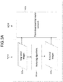
- FIG. 3A shows one exemplary embodiment for offline training data preparation S210.
- dataset generation starts off by gathering lower quality images 212, referred to in FIG. 3A as degraded images 312a, such as degraded clinical images of a patient.
- degraded images 312a such as degraded clinical images of a patient.
- one or more restoring algorithms are applied to the degraded images 312a.
- the restoring algorithms used in S311a can deblur and/or denoise the degraded images 312a to produce higher quality images 213, referred to in FIG. 3A as restored images 313a.
- Examples of restoring algorithms that can be used as the restoring algorithms S311a include, but are not limited to, semi- or un-supervised deep learning methods, non-local means methods, and Markov random field-based methods.
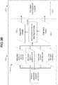
- FIG. 3B shows another exemplary embodiment for offline training data preparation S210.
- dataset generation starts off by gathering higher quality images 213, such as high-dose images 313b of one or more patients. Then, simulated realistic blurring and/or noise is added in S311b2 to the high-dose images 313b to produced lower quality images 212, referred to in FIG. 3B as degraded images 312b. These degraded images 312b and their corresponding high-dose images 313b can then be used for training the deep-learning neural network S221 in the offline training process S220.
- S311b1 comprises acquiring physical parameters of the apparatus.
- a variety of apparatus physical parameters can be incorporated, such as: measured or modelled blurring functions, measured or modelled quantum noise, measured or modelled electronic noise, spatial and temporal correlation, or any combination thereof.
- a measured or modelled blurring function can add realistic blurring caused from various factors such as light spreading caused by the scintillator, a finite focal spot size, patient motion, or detector binning.
- Realistic noise can include quantum noise and electronic noise.
- the spatial and temporal correlation from both quantum noise and electronic noise can be measured or modelled.
- FIG. 4A shows one embodiment for training the deep-learning neural network S221.
- a single lower quality image 412a is the input learning data
- a single corresponding improved quality image 413 is the output learning data.
- the deep-learning neural network 400 can be trained to find a set of weights that optimally map the lower quality image 412a to its corresponding improved quality image 413.
- the loss function for the deep-learning neural network 400 can be designed to minimize the noise-weighted difference between the lower quality image 412a (input) and the corresponding improved quality image 413 (target).
- the loss function can be a mean squared error/mean absolute error between the inferenced and target images. Additionally, a mask may be applied to focus on the specific parts of interest. Multiple lower quality images 412a and their corresponding high quality images 413 can be used for training the deep-learning neural network 400 until it is able to consistently produce acceptable higher quality images.
- FIG. 4B shows another embodiment for the training the deep-learning neural network S221.
- Time series lower quality images 412b can contain more information than a single lower quality image 412a, such as history information of how elements in the images have transformed over time.
- a time series of lower quality images 412b generated during the offline training data preparation S210 can be input learning data for the deep-learning neural network 400, and a single corresponding improved quality image 413 can be the target output.
- Temporal information can be used to reduce flickering.
- the loss function for the deep-learning neural network 400 can be designed to minimize the noise-weighted difference between the time series of lower quality images 412b (input) and a corresponding improved quality image 413 (target), as well as the noise-weighted difference between adjacent frames of the time series of lower quality images 412b.
- the loss function could be a mean squared error/mean absolute error between the inferenced and target images, as well as a mean squared error/mean absolute error between one or more previous frames and a current frame in the time series of images.
- a mask may be applied to focus on specific parts of interest. This process can be repeated until the deep-learning neural network 400 is sufficiently trained to produce acceptable higher quality images.
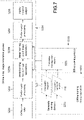
- FIG. 5 illustrates one exemplary embodiment for performing the online X-ray image restoration S230.
- This deep-learning neural network 400 can then be optimized (e.g. pruning, precision reduction) and used in the online X-ray image restoration process S230. For example, pruning a deep-learning neural network 400 deletes the connections between nodes constructing the deep-learning neural network 400 or the nodes themselves as needed, and can make the deep-learning neural network 400 lighter in weight. For example, reducing the accuracy of the deep-learning neural network 400 can improve the performance-cost ratio to the computation time and the power consumption of the deep-learning neural network 400.
- the online X-ray image restoration process S230 begins with collecting raw data S231.
- This raw data can be the data gathered by an imaging system for constructing an image.
- the raw data can include the X-ray transmitted through the object OBJ and detected by the two-dimensional array of detection elements in the detection system 114.
- the next step is performing pre-processing S232, which can be performed by one or more pre-processing circuitry 121 units.
- the pre-processing circuitry 121 can be configured to execute sensitivity correction, suppress distortions, or transform the raw data collected by the detection system 114 to a full size image 532.
- this full size image 532 can be further divided into snippets of image patches, IP1 through IPN, where N is the total number patches. Dividing the full size image 532 into image patches can enable more efficient processing.
- the full size image 532 can be divided in many different ways. For example, the full size image 532 can be divided into equal size regions, such as into quadrants or octants.
- the full size image 532 can be divided so that each image patch is a particular anatomical structure, such as a hand, chest, foot, leg, or skull.
- the full size image 532 can be divided so that each image patch is a subset of one or more slices.
- neighboring image patches can have overlap at their borders, which can ease reassembling the image patches back into a full size image later on in the process.
- these image patches IP1 to IPN can be used for deep learning based image restoration S233.
- the full size image 532 does not always have to be divided into snippets image patches (i.e. the full size image 532 can be used in S233).
- the next step is to perform deep learning based image restoration S233. In one embodiment, this can be performed by the image processing circuitry 122.
- the deep-learning neural network 400 after the deep-learning neural network 400 has been trained, it can optimized through pruning S501 and having its precision reduced S502 prior to being configured into one or more image restoration processors IRPs.
- pruning S501 can involve removing parameters from the deep-learning neural network 400 to reduce its size.
- S501 can include removing unnecessary weights in the deep-learning neural network 400 and may be performed iteratively.
- Performing precision reduction S502 can involve reducing the number of bits used in the deep-learning neural network 400, which can allow for faster arithmetic. For example, if the deep-learning neural network 400 was trained using 64-bits during the offline training process S220, S502 can decrease the bits used in computing to 32-bits, 16-bits, 8-bits, etc.
- a convolutional block attention module can be added to the deep-learning neural network 400.
- FIG. 6A illustrates an exemplary embodiment, where a CBAM 601 is attached to a U-net convolutional neural network right before concatenation.
- FIG. 6B shows an example of a CBAM 601, which include a channel attention module 603 and a spatial attention module 605.
- the CBAM can have either or both of the channel attention module 603 and a spatial attention module 605, and in either order.
- the CBAM can have light, trainable weights so that it can be flexibly attached to any neural network. The use of the CBAM can improve denoising and restoration performance of the deep-learning neural network 400.
- the deep-learning neural network 400 can be configured into one or more image restoration processors IRPs, which can be housed in the image processing circuitry 122.
- Multiple image restoration processors IRPs can be used in series or parallel to speed up the inferencing process.
- N image restoration processors can be configured in parallel to restore the N image patches.
- Each of the image patches IP1 - IPN can be input into an image restoration processor IRP for outputting a higher quality version (e.g. less blur, less noise) of the input image patch IP1 - IPN (or full size image 532).
- the use of multiple processors can accelerate the online inferencing process.
- these higher quality image patch IP1-IPN outputs can be collected and combined during post-processing S234 to create a transformed, higher quality full size image.
- S234 can be performed by the image-processing circuitry 122.
- parallel architectures such as single instruction, multiple data architectures
- this higher quality full size image can displayed using the display 123.
- an anatomic structure-based training strategy can be used to fully capture the image features at different anatomic structures and optimize the image quality.
- Training datasets can be classified based on anatomical structures.
- Multiple deep-learning neural networks 400 can be trained based on different training datasets. For example, a first deep-learning neural network 400 can be trained using high and low image pairs of a hand, while a second deep-learning neural network 400 can be trained using high and low image pairs of a skull.
- the first deep-learning neural network 400 can be configured into a first image restoration processor IRP1 for receiving image patches of hands, while the second deep-learning neural network 400 can be configured into a second image restoration processor IRP2 for receiving image patches of skulls.
- the training pairs can be used to train a network along with information on (a) the conditions under which the lower quality image was obtained or (b) the simulated conditions under which it was generated to appear to have been obtained.
- the neural network may be trained to correct noise and blur under image-specific conditions.
- the deep-learning neural network 400 that receives the first image as an input and outputs the first image with less noise and blur as a processed image is trained using the second image as input training data and the third image with less noise and blur compared with the second image as output training data, the first image, the second image, and the third image being of the same anatomical structure.
- the embodiment is not limited to the example, and a deep-learning neural network 400 may be trained using more segmented training data.
- multiple examination protocols may be set up for a particular anatomical structure.
- the examination protocol "coronary” for observing coronary arteries and the examination protocol "pediatric” established for a child may be set up for a heart.
- the examination protocol "chronic total occlusion (CTO)" established for the purpose of examining CTO and the examination protocol "ablation” established for the purpose of planning ablation therapy may be set up for a heart.
- CTO total occlusion
- ablation established for the purpose of planning ablation therapy
- These examination protocols differ in specific examination conditions, such as X-ray dose, for example.
- the deep-learning neural network 400 may be generated for each of these examination protocols.
- the deep-learning neural network 400 that receives the first image as an input and outputs the first image with less noise and blur as a processed image may be trained using the second image as input training data and the third image with less noise and blur compared with the second image as output training data, and the first image, the second image, and the third image may be based on the same examination protocol.
- the corresponding deep-learning neural network 400 can be selected and used as appropriate.
- the deep-learning neural network 400 can be selected based on the examination protocol of the first image to be input.
- the deep-learning neural network 400 trained using high and low image pairs of a hand and the deep-learning neural network 400 trained using high and low image pairs of a skull are present and the collected first image is of a hand of the patient
- the deep-learning neural network 400 trained using the high and low image pairs of a hand can be selected and used to reduce noise and blurring in the first image.
- one examination protocol may be associated with one deep-learning neural network 400, multiple examination protocols may be associated with one deep-learning neural network 400, or one examination protocol may be associated with multiple deep-learning neural networks 400.
- the same deep-learning neural network 400 may be associated with the examination protocol "CTO” established for the purpose of examining CTO and the examination protocol "ablation” established for the purpose of ablation treatment. That is, the deep-learning neural network 400 trained using the high and low image pairs of an anatomical structure, a "heart”, may be associated with the examination protocol "CTO” and the examination protocol "ablation”.
- the deep-learning neural network 400 trained using the high and low image pairs collected in the examination protocol "CTO” may be associated with the examination protocol "CTO"
- the deep-learning neural network 400 trained using the high and low image pairs collected in the examination protocol "ablation” may be associated with the examination protocol "ablation”.
- steps such as performing pre-processing S232, deep-learning based image restoration S233, and performing post-processing S234 can be chained together in series or in parallel and performed multiple times.
- a first deep-learning based image restoration step S233a can occur for removing noise using a first deep-learning neural network trained in S221 for removing noise, followed by a second deep-learning based image restoration step S233b using a second deep-learning neural network trained in S221 for removing blur.
- a second round of pre-processing S232, deep-learning based image restoration S233, and post-processing S234 can be performed where the image patches are divided using a different technique, such as into one or more slices or specific anatomical parts.
- the training data preparation S210 and training process S220 can be implemented as software.
- a computer processor having embedded memory can store computer instructions for performing the processes described herein.
- the training data preparation S210 and training process S220 can be implemented as hardware.
- the processes described above can be implemented in processing circuitry, such as an application specific integrated circuit (ASIC) or a field programmable gate array (FPGA).
- the FPGA may be programmed as a trained neural network at hardware startup, or the FPGA may be reprogrammed as a new, special purpose neural network each time the usage conditions change (e.g., when changing from a hand-specific neural network to a skull-specific neural network, or when changing from an image taken at a first radiation dose or expose to a second radiation dose or exposure).
- the above mentioned techniques can be implemented as a method.
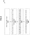
- One method 700 for training and utilizing a deep-learning neural network for image restoration is illustrated in FIG. 8 .
- the first step S710 is to obtain one or more high quality images. These images can be high quality clinical images of patients.
- the next step S720 is to create one or more lower quality images by adding blur and noise to the high quality images obtained in S710.
- the noise and blur to be added can be dependent on parameters of the apparatus used to obtain the high quality images. Examples of factors that can be considered include measured or modelled blurring, measured or modelled quantum noise, measured or modelled electronic noise, and spatial and temporal correlation.
- the goal is to create one or more images that have more blur and noise than the high quality images.
- the next step S730 is to train a deep-learning neural network by using the high quality images as the output target and the low quality images as the input. Once the deep-learning neural network has been trained, the trained deep-learning neural network can be pruned and precision reduced for use in real-time inferencing S740.
- the first step S810 is to obtain one or more low quality images S810, such as noisy or blurry clinical X-ray images of patients.
- the next step S820 is to create high quality images by deblurring and denoising the lower quality images obtained in S810.
- Algorithms that can be used to remove blur and noise include, but are not limited to, semi- or un-supervised deep learning methods, non-local means methods, and Markov random field-based methods.
- the goal is to create higher quality images with less blur and noise than the low quality images obtained in S810.
- the next step 830 is to train a deep-learning neural network by using the higher quality images as the output target and the low quality images as the input. Once the deep-learning neural network has been trained, the trained deep-learning neural network can be pruned and precision reduced used for real-time inferencing S840.
- the input into the deep-learning neural network can be a single frame and a loss function can be designed to minimize the noise-weighted difference between the input and the target output.
- the input can be multiple frames, and the loss function can be designed to minimize the noise-weighted difference between the multi-frame inputs and the target output, as well as the noise-weighted difference between adjacent frames.
- the method 900 starts with obtaining raw data S941.
- Obtaining raw data can include collecting information from scanning a patient during an X-ray.
- the next step S942 is to pre-process the raw data. Pre-processing the raw data can include using the raw data to create a full size image. Further, this image can be divided into snippets of image patches.
- the next step S943 is to perform image reconstruction S943. The full size image or image patches generated from S942 can be input into the trained deep-learning neural network.
- the deep-learning neural network can then output higher quality images of the input, wherein the higher quality images have reduced blur and noise.
- the next step S944 is to perform post-processing, which can include putting the new and improved image together. If pre-processing the raw data S942 involved creating image patches, the post-processing S944 can put the newly generated image patches back together to form a full size image. Lastly, the restored output can be displayed S945.
- FIG. 11 illustrates another exemplary embodiment of a method 1000 for using the trained deep-learning neural network for real-time image restoration.
- a first image is input to a learned model, where the learned model can be the trained deep-learning neural network produced according to method 700 or 800.
- the first image can be made with raw data obtained during an X-ray scan of a patient.
- the first image is output from the learned model with less noise and blur than when it was input in S1041.
- FIG. 12 illustrates a workflow for one embodiment of dataset generation that can be used in training.
- a manipulated non-medical dataset 1101 is first obtained.
- This manipulated non-medical dataset 1101 does not need to be an actual medical image (e.g. patient scan), thereby encompassing a wide range of possible datasets that can be used.
- manipulation refers to transforming a non-medical dataset to resemble an X-ray dataset using any technique known by one of skill in the art.
- a non-medical dataset is manipulated to resemble an X-ray dataset, thereby forming the manipulated non-medical dataset 1101.
- the manipulated non-medical dataset 1101 is corrupted to generate a corresponding corrupted manipulated non-medical dataset 1103.
- Various forms of corruption can be included, such as adding noise or blur.
- the techniques described with respect step S311b2 in FIG. 3B can be applied.
- a deep learning neural network is trained using the manipulated non-medical dataset 1101 as output learning data, and the corresponding corrupted manipulated non-medical dataset 1103 as input learning data.
- the training can be performed until a predetermined stopping criteria has been met.
- the outcome of S1107 is deep-learning neural network 1109.
- the deep-learning neural network 1109 can now take as input X-ray images 1111, which are medical images, and generate high quality X-ray images 1113.
- the high quality X-ray images 1113 are corrupted to produce corresponding low quality X-ray images 1112.
- the same corruption technique as described in S311b2 of FIG. 3B can be applied.
- S1121 is to train a deep-learning neural network using the high quality X-ray images 1113 as output training data, and the low quality X-ray images 1112 as input training data. Once S1121 has been completed, the trained neural network can be used for deep-learning based image restoration, as previously described in S233.
- Metadata can be incorporated, such as a patient's condition (e.g. patient's body mass index) or a description of an image (e.g. procedure that generated the image).
- the deep-learning neural network trained in S1121 can use low quality X-ray images 1112 (input training data), high quality X-ray images 113 (output training data), and metadata (input training data) during training.
- metadata can be used to further corrupt the low quality X-ray images 1112.
- a different kernel that can simulate more realistic images can be used to corrupt the low quality X-ray images 1112.
- the metadata can be an additional input in the deep-learning based image restoration of S233.
- FIG. 13 illustrates another workflow for offline data generation in S1120 similar to the workflow discussed in FIG. 12 .
- multiple neural networks can be trained to take X-ray images of multiple types.
- manipulated non-medical dataset 1101a and manipulated non-medical dataset 1101b are obtained. These two datasets can differ in that they have different features and resemble different types of 2-D X-ray scan datasets.
- manipulated non-medical dataset 1101a can resemble a dataset from a percutaneous coronary intervention (PCI) procedure
- manipulated non-dataset 1101b can resemble a dataset from a pacemaker procedure.
- PCI percutaneous coronary intervention
- each of manipulated non-medical dataset 1101a and manipulated non-medical dataset 1101b are corrupted in S1105a and 1105b (respectively) to generate corresponding manipulated corrupted non-medical dataset 1103a and corresponding manipulated corrupted non-medical dataset 1103b (respectively).
- S1107a the manipulated non-medical dataset 1101a is used as output training data, and the corresponding manipulated corrupted non-medical dataset 1103a is used as input training data to generate trained deep-learning neural network 1109a.
- the manipulated non-medical dataset 1101b is used as output training data, and the corresponding manipulated corrupted non-medical dataset 1103b is used as input training data to generate a trained deep-learning neural network 1109b.
- X-ray images 1111a can be input into deep-learning neural network 1109a
- X-ray images 1111b can be input into deep-learning neural network 1109b
- X-ray images 1111a can be medical images that the manipulated non-medical dataset 1101a originally aimed to resemble
- X-ray images 1111b can be medical images that the manipulated non-medical dataset aimed to resemble.
- the X-ray images 1111a can be actual PCI images.
- the trained deep-learning neural networks 1109a and 1109b output high quality X-ray images 1113, where the high quality X-ray images 1113 include high quality versions of X-ray images 1111a and X-ray images 1111b. Each of the high quality X-ray images 1113 are corrupted in S1115 to generate their corresponding low quality X-ray images 1112.
- a deep-learning neural network is trained using the high quality X-ray images 1113 as output training data, and their corresponding low quality X-ray images 1112 as input training data.
- the trained deep-learning neural network can be used in the online X-ray image restoration process as described in S230.
- FIG. 14 illustrates another workflow for offline data generation S1120, according to one embodiment.
- a manipulated non-medical dataset 1101 is obtained, as described in FIG. 12 .
- the manipulated non-medical dataset 1101 is corrupted to generate a corresponding corrupted manipulated non-medical dataset 1103, also as described in FIG. 12 .
- a deep learning neural network is trained using the manipulated non-medical dataset 1101 as output learning data, and the corresponding corrupted manipulated non-medical dataset 1103 as input learning data.
- the deep-learning neural network can be used directly in deep-learning based image restoration of S233.
- the method and system described herein can train and utilize a deep-learning neural network for creating higher quality images by removing noise and blur in real-time.
- the proposed techniques have various advantages that can result in an improved performance in both quality and speed. Examples of such advantages include, but are not limited to: these concepts can handle blurring and noise jointly; these concepts can be applied to X-ray imaging; these concepts can take into account physics and apparatus related variations; these concepts can use time-sequence data; these concepts can accelerate and improve the efficiency of the overall restoration process (e.g. by cropping an image, using multiple processors in series or parallel, pruning the deep-learning neural network, reducing the precision of the deep-learning neural network); these techniques are not limited to only cardiac purposes; and these techniques can utilize anatomical-based training datasets.
- the processing circuitry e.g., image processing circuitry and controller circuitry
- the processing circuitry is implemented as one of or as a combination of: an application specific integrated circuit (ASIC), a field programmable gate array (FPGA), a generic array of logic (GAL), a programmable array of logic (PAL), circuitry for allowing one-time programmability of logic gates (e.g., using fuses) or reprogrammable logic gates.
- ASIC application specific integrated circuit
- FPGA field programmable gate array
- GAL generic array of logic
- PAL programmable array of logic
- the processing circuitry can include a computer processor and having embedded and/or external non-volatile computer readable memory (e.g., RAM, SRAM, FRAM, PROM, EPROM, and/or EEPROM) that stores computer instructions (binary executable instructions and/or interpreted computer instructions) for controlling the computer processor to perform the processes described herein.
- the computer processor circuitry may implement a single processor or multiprocessors, each supporting a single thread or multiple threads and each having a single core or multiple cores.
- the processing circuitry used to train the artificial neural network need not be the same as the processing circuitry used to implement the trained artificial neural network that performs the calibration described herein.
- processor circuitry and memory may be used to produce a trained artificial neural network (e.g., as defined by its interconnections and weights), and an FPGA may be used to implement the trained artificial neural network.
- a trained artificial neural network e.g., as defined by its interconnections and weights
- an FPGA may be used to implement the trained artificial neural network.
- the training and use of a trained artificial neural network may use a serial implementation or a parallel implementation for increased performance (e.g., by implementing the trained neural network on a parallel processor architecture such as a graphics processor architecture).
- Embodiments of the present disclosure may also be set forth in the following parentheticals.
Landscapes
- Engineering & Computer Science (AREA)
- Health & Medical Sciences (AREA)
- Physics & Mathematics (AREA)
- Life Sciences & Earth Sciences (AREA)
- Theoretical Computer Science (AREA)
- General Health & Medical Sciences (AREA)
- Medical Informatics (AREA)
- General Physics & Mathematics (AREA)
- Biophysics (AREA)
- Molecular Biology (AREA)
- Biomedical Technology (AREA)
- Nuclear Medicine, Radiotherapy & Molecular Imaging (AREA)
- Radiology & Medical Imaging (AREA)
- Public Health (AREA)
- Software Systems (AREA)
- Artificial Intelligence (AREA)
- General Engineering & Computer Science (AREA)
- Computing Systems (AREA)
- Evolutionary Computation (AREA)
- Data Mining & Analysis (AREA)
- Mathematical Physics (AREA)
- Computational Linguistics (AREA)
- Veterinary Medicine (AREA)
- High Energy & Nuclear Physics (AREA)
- Optics & Photonics (AREA)
- Pathology (AREA)
- Heart & Thoracic Surgery (AREA)
- Surgery (AREA)
- Animal Behavior & Ethology (AREA)
- Primary Health Care (AREA)
- Epidemiology (AREA)
- Computer Vision & Pattern Recognition (AREA)
- Image Processing (AREA)
- Image Analysis (AREA)
- Apparatus For Radiation Diagnosis (AREA)
Abstract
Description
- The method and system described herein are directed to restoration of X-ray images, and in one embodiment to the restoration of X-ray images using deep learning algorithms.
- The background description provided herein is for the purpose of generally presenting the context of the disclosure. Work of the presently named inventors, to the extent the work is described in this background section, as well as aspects of the description that may not otherwise qualify as prior art at the time of filing, are neither expressly nor impliedly admitted as prior art against the present disclosure.
- X-ray images tend to be blurry and noisy. Blurring and noise in radiography can make analyzing images difficult, and can lead to misdiagnoses. Scans using higher doses of x-rays can be used to create sharper images, but higher doses of x-rays can be dangerous for patients. On the other hand, scans performed at reduced doses come at the cost of increasing noise. This trade-off is especially apparent for time series acquisitions, where long exposure time is not possible, such as for cardiac catheterization with fluoroscopy.
- Some image restoration techniques can involve reducing blur, but this comes at the cost of increasing noise. Other techniques can reduce noise, but this comes at the cost of artifacts. Further, image restoration techniques often cause unnatural textures, ringing artifacts, require hand-turning of filter parameters, are computationally expensive, and are hard to implement.
- In light of the above mentioned problems, there exists a need to improve techniques related to deblurring and denoising X-ray images.
- An X-ray diagnosis apparatus, comprising:
processing circuitry configured to: - input a first image to a learned model; and
- output the first X-ray image with less noise and blur as a processed image, wherein the learned model is trained by using a second X-ray image as input learning data and a third X-ray image with less noise and blur than the second X-ray image as output learning data.
- The third X-ray image may be obtained by deblurring and denoising the second X-ray image.
- The second X-ray image may be obtained by adding blur and noise to the third X-ray image.
- The processing circuitry may further be configured to prune the learned model after the learned model has been trained.
- The processing circuitry may further be configured to reduce precision of the learned model after the learned model has been trained.
- At least one of the first X-ray image, the second X-ray image, and the third X-ray image is a fluoroscopic image.
- The first X-ray image, the second X-ray image, and the third X-ray image may be of a same anatomic structure.
- The first X-ray image, the second X-ray image, and the third X-ray image may be of an examination protocol
- The processing circuitry may select learned model corresponding to the examination protocol of the first X-ray image from a plurality of the learned model.
- The third X-ray image may be a manipulated non-medical dataset, and the second X-ray image may be the manipulated non-medical dataset with corruption.
- A second learned model may be trained to take a fourth X-ray image as an input and output the third X-ray image, the second learned model trained using a manipulated non-medical dataset as output learning data, and the manipulated non-medical dataset with corruption as input learning data.
- The blur may be a reduction in the spatial resolution of X-ray image.
- The blur may be caused from at least one of light spreading caused by the scintillator, a finite focal spot size, patient motion and detector binning.
- The second X-ray image may be a plurality of X-ray images.
- The learned model may be a deep-learning neural network.
- The learned model may be a convolutional block attention module.
- The learned model may be a U-net convolutional neural network
- The convolutional block attention module may be attached to a U-net convolutional neural network right before concatenation.
- The pruning the learned model may be deleting connections a deep-learning between nodes constructing the deep-learning neural network
- The pruning may be deleting nodes used in the deep-learning neural network.
- The reducing precision of the learned model may be reducing the number of bits used in the deep-learning neural network.
- The first X-ray image may be a snippet of a full size image.
- A method for image restoration comprising:
- inputting a first X-ray image to a learned model; and
- outputting the first X-ray image with less noise and blur as a processed image,
- wherein the learned model is trained by using a second X-ray image as input learning data and a third X-ray image with less noise and blur than the second X-ray image as output learning data.
- The second X-ray image may be obtained by deblurring and denoising the first X-ray image.
- The first X-ray image may be obtained by adding blur and noise to the second X-ray image.
- The method may further comprise pruning the learned model after the learned model has been trained.
- The method may further comprise reducing precision of the learned model after the learned model has been trained.
- The third X-ray image may be a manipulated non-medical dataset, and the second X-ray image may be the manipulated non-medical dataset with corruption.
- A second learned model may be trained to take a fourth X-ray image as an input and output the third X-ray image, the second learned model trained using a manipulated non-medical dataset as output learning data, and the manipulated non-medical dataset with corruption as input learning data.
- The first X-ray image, the second X-ray image, and the third X-ray image may be of a same anatomic structure.
- The blur may be a reduction in the spatial resolution of X-ray image.
- The blur may be caused from at least one of light spreading caused by the scintillator, a finite focal spot size, patient motion and detector binning.
- The second X-ray image may be a plurality of X-ray images.
- The learned model may be a deep-learning neural network.
- The learned model may be a convolutional block attention module.
- The learned model may be a U-net convolutional neural network
- The convolutional block attention module may be attached to a U-net convolutional neural network right before concatenation.
- The pruning the learned model may be deleting connections a deep-learning between nodes constructing the deep-learning neural network
- The pruning may be deleting nodes used in the deep-learning neural network.
- The reducing precision of the learned model may be reducing the number of bits used in the deep-learning neural network.
- The first X-ray image may be a snippet of a full size image.
- A non-transitory computer-readable medium including computer-readable instructions that, when executed by a computing system, cause the computing system to sort data by performing a method comprising:
- inputting a first X-ray image to a learned model; and
- outputting the first X-ray image with less noise and blur,
- wherein the learned model is trained by using a second X-ray image as input learning data and a third X-ray image with less noise and blur than the second X-ray image as output learning data.
- A method for training a machine learning model, the method comprising:
- training the machine learning model by using a second X-ray image as input learning data and a third X-ray image with less noise and blur than the second X-ray image as output learning data,
- wherein the trained machine learning model receives a first X-ray image as an input image and output the first X-ray image with less noise and blur as a processed image.
-
-
FIG. 1 is an X-ray system, according to one exemplary embodiment of the present disclosure; -
FIG. 2 is workflow diagram for imaging restoration using deep learning algorithms, according to one exemplary embodiment of the present disclosure; -
FIG. 3A is a workflow diagram for training data preparation, according to one exemplary embodiment of the present disclosure; -
FIG. 3B is a workflow diagram for training data preparation, according to one exemplary embodiment of the present disclosure; -
FIG. 4A is a workflow diagram of a training process, according to one exemplary embodiment of the present disclosure; -
FIG. 4B is a workflow diagram of a training process, according to one exemplary embodiment of the present disclosure; -
FIG. 5 is a workflow diagram of an X-ray image restoration process, according to one exemplary embodiment of the present disclosure; -
FIG. 6A illustrates a convolutional block attention module (CBAM) attached onto a U-net, according to one exemplary embodiment of the present disclosure; -
FIG. 6B illustrates an architecture of a CBAM, according to one exemplary embodiment of the present disclosure; -
FIG. 7 is a workflow diagram of an X-ray image restoration process, according to one exemplary embodiment of the present disclosure; -
FIG. 8 is a method for training a deep-learning neural network, according to one exemplary embodiment of the present disclosure; -
FIG. 9 is a method for training a deep-learning neural network, according to one exemplary embodiment of the present disclosure; -
FIG. 10 is a method for obtaining an image with less blur and noise using a trained deep-learning neural network; and -
FIG. 11 is a method for obtaining an image with less blur and noise using a trained deep-learning neural network. -
FIG. 12 is a workflow diagram illustrating the use of manipulated non-medical datasets to generate high quality X-ray images for training a neural network for online X-ray image restoration. -
FIG. 13 is a workflow diagram illustrating the use of multiple types of manipulated non-medical datasets to generate multiple types of high quality X-ray images for training a neural network for online X-ray image restoration. -
FIG. 14 is a workflow diagram illustrating the use of manipulated non-medical datasets to train a neural network for online X-ray image restoration. - The following disclosure provides many different embodiments, or examples, for implementing different features of the provided subject matter. Specific examples of components and arrangements are described below to simplify the present disclosure. These are, of course, merely examples and are not intended to be limiting. In addition, the present disclosure may repeat reference numerals and/or letters in the various examples. This repetition is for the purpose of simplicity and clarity and does not in itself dictate a relationship between the various embodiments and/or configurations discussed.
- The order of discussion of the different steps as described herein has been presented for the sake of clarity. In general, these steps can be performed in any suitable order. Additionally, although each of the different features, techniques, configurations, etc. herein may be discussed in different places of this disclosure, it is intended that each of the concepts can be executed independently of each other or in combination with each other. Accordingly, the present invention can be embodied and viewed in many different ways. This disclosure describes an X-ray detector to illustrate the various embodiments, but these concepts can be applied to similar systems, such as single-photon emission computed tomography (SPECT) systems, magnetic resonance imaging (MRI) systems, ultrasound systems, computed tomography (CT) systems, PET-CT systems, etc.. The imaging techniques discussed herein can be applied to any X-ray imaging technique that can generate 2D X-ray images, such as chest X-rays, mammography, and angiography. Further, as used herein, the words "a", "an" and the like generally carry a meaning of "one or more", unless stated otherwise.
- This disclosure is related to a system and method for restoring images using deep learning algorithms. In one embodiment, the deep learning algorithms can include using a neural network, such as a deep-learning neural network, and the images being restored can include X-ray images. This disclosure will describe a workflow with three aspects: (i) training data preparation, (ii) the training process, and (iii) the image restoration process.
- The training data preparation aspect will be described with reference to two techniques: (i) deblurring and denoising images and (ii) degrading images. The training preparation aspect will be described with respect to two exemplary techniques: (i) mapping a single lower quality image to a single higher quality image, and (ii) mapping a time series of lower quality images to a single higher quality image. The X-ray image restoration process will be described with respect to how to use the trained deep-learning neural network for real-time inferencing.
- In one aspect, it can be appreciated that the present disclosure may be implemented within an X-ray apparatus.
FIG. 1 is an exemplary X-ray apparatus that can be used with the disclosed techniques and structures. The X-ray apparatus includes agantry 100 and aconsole 120. Thegantry 100 includes anX-ray source system 111, a beam-shapingsystem 112, a patient table 113, adetection system 114, and a gantrycontrol transmission circuitry 115. TheX-ray source system 111 includes ahigh voltage generator 110 and anX-ray tube 101. Thehigh voltage generator 110 applies a high voltage to theX-ray tube 101 under the control of the gantrycontrol transmission circuitry 115, and supplies a filament current to theX-ray tube 101 under the control of the gantrycontrol transmission circuitry 115. TheX-ray tube 101 generates X-rays to irradiate an object OBJ (e.g., a patient) upon receiving a trigger from thehigh voltage generator 110. Thecollimation system 112 includes a beam filter/attenuator 116 which modifies the spectrum of the X-ray beam from theX-ray tube 101. Acollimator 117 opens and closes in accordance with a field of view selected at the time of the operation. Thecollimation system 112 forms an X-ray beam and irradiates the object OBJ (e.g., a patient) with X-rays. - The
detection system 114 includes a two-dimensional array of detection elements (pixels) configured to absorb the X-ray transmitted through the object OBJ (e.g., a patient) and generate an electrical charge signal proportional to the absorbed X-ray intensity. The electrical signal of each pixel is amplified and converted to a digital number by A/D converters. For example, thedetection system 114 includes thedetector 103 and a data acquisition system (DAS) 104. Thedetector 103 detects the X-rays generated from theX-ray tube 101. Thedetector 103 is equipped with a plurality of detection elements arrayed two-dimensionally. Each detection element detects the X-rays generated from theX-ray tube 101 and generates an electrical signal (current signal) corresponding to the intensity of the detected X-rays. - The generated electrical signal is supplied to the
DAS 104. TheDAS 104 includes anamplifier 104A, an A/D converter 104B, and acontrol panel 104C. TheDAS 104 reads out electrical signals via thedetector 103 and obtains the readout electrical signals, via thecontrol panel 104C. The gantrycontrol transmission circuitry 115 controls thehigh voltage generator 110, theattenuator 116, thecollimator 117, and thecontrol panel 104C to execute X-ray imaging. - The
console 120 includespre-processing circuitry 121, image-processing circuitry 122, adisplay 123, anoperation device 124,data storage 125, andsystem control circuitry 126. Thepre-processing circuitry 121 executes pre-processing, such as sensitivity correction for raw data supplied from thedetection system 114, via the gantrycontrol transmission circuitry 115 which can be circuitry for controlling a wired interface (e.g., serial connection circuitry (such as USB connection circuitry), Ethernet connection circuitry, optical connection circuitry) or controlling a wireless interface (e.g., any of the 802.11 families of protocols). Although theconsole 120 is illustrated as co-located with the gantry 100 (e.g., within the same room or in adjacent rooms), thegantry 100 and theconsole 120 may be remotely located from each other (e.g., in different areas of the same floor, on different floors, and in different buildings). Moreover, image processing described herein as being performed by theconsole 120 may be off-loaded to a secondary processing device (not shown) such as an image processing computer. - The image-
processing circuitry 122 can perform the image-processing methods. Thedisplay 123 displays the image generated by the image-processing circuitry 122. Theoperation circuitry 124 accepts various types of commands and information inputs from a user, via an input device. The data storage (memory) 125 stores the raw data and various types of data, such as projection data and images. In addition, thedata storage 125 stores control programs for the X-ray apparatus, and control programs for performing the image-processing methods described herein. Thesystem control circuitry 126 functions as the main circuitry of the X-ray apparatus. Thesystem control circuitry 126 reads out control programs stored in thedata storage 125 and loads the programs into the memory. Thesystem control circuitry 126 controls the respective circuitry in the X-ray apparatus in accordance with the loaded control programs. Thesystem control circuitry 126 can be configured to run any of the methods and workflows described in the present disclosure. -
FIG. 2 illustrates a general workflow according to one exemplary embodiment, which includes offline training data preparation S210, an offline training process S220, and online X-ray image restoration S230. The workflow begins with offline training data preparation S210. Step S210 includes generating (S211) training datasets to produce one or morelower quality images 212 corresponding to a number ofhigher quality images 213. Eachlower quality image 212 has more noise and blur than its correspondinghigher quality image 213. Theselower quality images 212 andhigher quality images 213 can then be used as training data to train the deep-learning neural network S211 in the offline training process S220, using thelower quality images 212 as an input and their correspondinghigher quality images 213 as the target output, thereby producing a trained deep-learning neural network. The training can include updating weights in the deep-learning neural network to map the input to the target output. - The trained deep-learning neural network produced upon completion of the offline training process S220 can then be used for real-time, online X-ray image restoration S230. This process begins with the step of collecting raw data S231, such as X-ray data from a scan of the object OBJ. This raw data is then pre-processed in S232 to create an initial image. This initial, full size image can then be snipped (i.e., segmented or cropped) to create image patch snippets making up the full sized image. The image patch snippets are then input into one or more deep-learning neural networks trained during S221 to perform deep-learning based image restoration S233, which outputs a higher quality version of the input image. The improvement in quality can be in the form of less blur or noise. The image is then post-processed S234. For example, if image patch snippets were created, they can be put back together to form a whole, full size image. Upon performing post-processing S234, the restored output can be displayed S235 to a user.
- Additional details of the general workflow of
FIG. 2 will be discussed with reference to additional figures.FIGs 3A ,3B ,4A , and4B will be used to facilitate a discussion on generating training datasets and training the deep-learning neural networks, andFIG. 5 will be used to facilitate a discussion on utilizing the trained deep-learning neural network for real-time image restoration. -
FIG. 3A shows one exemplary embodiment for offline training data preparation S210. In this example, dataset generation starts off by gatheringlower quality images 212, referred to inFIG. 3A asdegraded images 312a, such as degraded clinical images of a patient. Then, in S311a, one or more restoring algorithms are applied to thedegraded images 312a. The restoring algorithms used in S311a can deblur and/or denoise thedegraded images 312a to producehigher quality images 213, referred to inFIG. 3A as restoredimages 313a. Examples of restoring algorithms that can be used as the restoring algorithms S311a include, but are not limited to, semi- or un-supervised deep learning methods, non-local means methods, and Markov random field-based methods. Note that even though these restoring algorithms can be used to deblur and/or denoise images to some extent, they are often computationally consuming and inconsistent in producing high quality results compared to the techniques discussed herein. Thesedegraded images 312a and their corresponding restoredimages 313a can then be used for training the deep-learning neural network S221 in the offline training process S220. -
FIG. 3B shows another exemplary embodiment for offline training data preparation S210. In this example, dataset generation starts off by gatheringhigher quality images 213, such as high-dose images 313b of one or more patients. Then, simulated realistic blurring and/or noise is added in S311b2 to the high-dose images 313b to producedlower quality images 212, referred to inFIG. 3B asdegraded images 312b. Thesedegraded images 312b and their corresponding high-dose images 313b can then be used for training the deep-learning neural network S221 in the offline training process S220. - Because different physical parameters in the apparatus can generate different blurring functions and noise properties (e.g. an X-ray system will have different noise, blurring, and correlation factors than a PET scanner system), they can be considered separately during S311b1 when determining the simulated realistic blurring and noise to be added during S311b2. S311b1 comprises acquiring physical parameters of the apparatus.
- During S311b1, a variety of apparatus physical parameters can be incorporated, such as: measured or modelled blurring functions, measured or modelled quantum noise, measured or modelled electronic noise, spatial and temporal correlation, or any combination thereof. In one embodiment, a measured or modelled blurring function can add realistic blurring caused from various factors such as light spreading caused by the scintillator, a finite focal spot size, patient motion, or detector binning. Realistic noise can include quantum noise and electronic noise. Furthermore, the spatial and temporal correlation from both quantum noise and electronic noise can be measured or modelled. It should be understood that the above-mentioned techniques are just a few of many ways that high quality images can be degraded to create lower quality images. Accordingly, it can be appreciated that many other techniques can be used for accomplishing the overall purpose of this step.
-
FIG. 4A shows one embodiment for training the deep-learning neural network S221. A singlelower quality image 412a is the input learning data, and a single correspondingimproved quality image 413 is the output learning data. The deep-learningneural network 400 can be trained to find a set of weights that optimally map thelower quality image 412a to its correspondingimproved quality image 413. In one embodiment, the loss function for the deep-learningneural network 400 can be designed to minimize the noise-weighted difference between thelower quality image 412a (input) and the corresponding improved quality image 413 (target). In one embodiment, the loss function can be a mean squared error/mean absolute error between the inferenced and target images. Additionally, a mask may be applied to focus on the specific parts of interest. Multiplelower quality images 412a and their correspondinghigh quality images 413 can be used for training the deep-learningneural network 400 until it is able to consistently produce acceptable higher quality images. -
FIG. 4B shows another embodiment for the training the deep-learning neural network S221. Time serieslower quality images 412b can contain more information than a singlelower quality image 412a, such as history information of how elements in the images have transformed over time. Thus, in another exemplary embodiment, a time series oflower quality images 412b generated during the offline training data preparation S210 can be input learning data for the deep-learningneural network 400, and a single correspondingimproved quality image 413 can be the target output. Temporal information can be used to reduce flickering. The loss function for the deep-learningneural network 400 can be designed to minimize the noise-weighted difference between the time series oflower quality images 412b (input) and a corresponding improved quality image 413 (target), as well as the noise-weighted difference between adjacent frames of the time series oflower quality images 412b. For example, the loss function could be a mean squared error/mean absolute error between the inferenced and target images, as well as a mean squared error/mean absolute error between one or more previous frames and a current frame in the time series of images. Additionally, a mask may be applied to focus on specific parts of interest. This process can be repeated until the deep-learningneural network 400 is sufficiently trained to produce acceptable higher quality images. -
FIG. 5 illustrates one exemplary embodiment for performing the online X-ray image restoration S230. After generating training datasets S211 during offline training data preparation S210 to produce high/low image pairs 212, 213, they can be used to train the deep-learningneural network 400 in the offline training process S220. This deep-learningneural network 400 can then be optimized (e.g. pruning, precision reduction) and used in the online X-ray image restoration process S230. For example, pruning a deep-learningneural network 400 deletes the connections between nodes constructing the deep-learningneural network 400 or the nodes themselves as needed, and can make the deep-learningneural network 400 lighter in weight. For example, reducing the accuracy of the deep-learningneural network 400 can improve the performance-cost ratio to the computation time and the power consumption of the deep-learningneural network 400. - The online X-ray image restoration process S230 begins with collecting raw data S231. This raw data can be the data gathered by an imaging system for constructing an image. For example, the raw data can include the X-ray transmitted through the object OBJ and detected by the two-dimensional array of detection elements in the
detection system 114. - The next step is performing pre-processing S232, which can be performed by one or more
pre-processing circuitry 121 units. Thepre-processing circuitry 121 can be configured to execute sensitivity correction, suppress distortions, or transform the raw data collected by thedetection system 114 to afull size image 532. In one embodiment, thisfull size image 532 can be further divided into snippets of image patches, IP1 through IPN, where N is the total number patches. Dividing thefull size image 532 into image patches can enable more efficient processing. Thefull size image 532 can be divided in many different ways. For example, thefull size image 532 can be divided into equal size regions, such as into quadrants or octants. As another example, thefull size image 532 can be divided so that each image patch is a particular anatomical structure, such as a hand, chest, foot, leg, or skull. As another example, thefull size image 532 can be divided so that each image patch is a subset of one or more slices. Additionally, neighboring image patches can have overlap at their borders, which can ease reassembling the image patches back into a full size image later on in the process. Next, these image patches IP1 to IPN can be used for deep learning based image restoration S233. As can be appreciated, thefull size image 532 does not always have to be divided into snippets image patches (i.e. thefull size image 532 can be used in S233). - The next step is to perform deep learning based image restoration S233. In one embodiment, this can be performed by the
image processing circuitry 122. In one embodiment, after the deep-learningneural network 400 has been trained, it can optimized through pruning S501 and having its precision reduced S502 prior to being configured into one or more image restoration processors IRPs. Performing pruning S501 can involve removing parameters from the deep-learningneural network 400 to reduce its size. S501 can include removing unnecessary weights in the deep-learningneural network 400 and may be performed iteratively. Performing precision reduction S502 can involve reducing the number of bits used in the deep-learningneural network 400, which can allow for faster arithmetic. For example, if the deep-learningneural network 400 was trained using 64-bits during the offline training process S220, S502 can decrease the bits used in computing to 32-bits, 16-bits, 8-bits, etc. - In an embodiment, a convolutional block attention module (CBAM) can be added to the deep-learning
neural network 400.FIG. 6A illustrates an exemplary embodiment, where aCBAM 601 is attached to a U-net convolutional neural network right before concatenation.FIG. 6B shows an example of aCBAM 601, which include achannel attention module 603 and aspatial attention module 605. In an embodiment, the CBAM can have either or both of thechannel attention module 603 and aspatial attention module 605, and in either order. In an embodiment, the CBAM can have light, trainable weights so that it can be flexibly attached to any neural network. The use of the CBAM can improve denoising and restoration performance of the deep-learningneural network 400. - After the deep-learning
neural network 400 has been optimized, it can be configured into one or more image restoration processors IRPs, which can be housed in theimage processing circuitry 122. Multiple image restoration processors IRPs can be used in series or parallel to speed up the inferencing process. For example, N image restoration processors can be configured in parallel to restore the N image patches. Each of the image patches IP1 - IPN can be input into an image restoration processor IRP for outputting a higher quality version (e.g. less blur, less noise) of the input image patch IP1 - IPN (or full size image 532). The use of multiple processors can accelerate the online inferencing process. Next, these higher quality image patch IP1-IPN outputs can be collected and combined during post-processing S234 to create a transformed, higher quality full size image. S234 can be performed by the image-processing circuitry 122. (Similarly, parallel architectures (such as single instruction, multiple data architectures) can be used for enhanced performance.) In displaying the restored output S235, this higher quality full size image can displayed using thedisplay 123. - In one embodiment, during the training data preparation S210 and training process S220, an anatomic structure-based training strategy can be used to fully capture the image features at different anatomic structures and optimize the image quality. Training datasets can be classified based on anatomical structures. Multiple deep-learning
neural networks 400 can be trained based on different training datasets. For example, a first deep-learningneural network 400 can be trained using high and low image pairs of a hand, while a second deep-learningneural network 400 can be trained using high and low image pairs of a skull. During S230, the first deep-learningneural network 400 can be configured into a first image restoration processor IRP1 for receiving image patches of hands, while the second deep-learningneural network 400 can be configured into a second image restoration processor IRP2 for receiving image patches of skulls. Similarly, the training pairs can be used to train a network along with information on (a) the conditions under which the lower quality image was obtained or (b) the simulated conditions under which it was generated to appear to have been obtained. In doing so, the neural network may be trained to correct noise and blur under image-specific conditions. - An example using the same anatomical structure data as the learning data for the deep-learning
neural network 400 has been explained. More specifically, in the example as explained here, the deep-learningneural network 400 that receives the first image as an input and outputs the first image with less noise and blur as a processed image is trained using the second image as input training data and the third image with less noise and blur compared with the second image as output training data, the first image, the second image, and the third image being of the same anatomical structure. The embodiment, however, is not limited to the example, and a deep-learningneural network 400 may be trained using more segmented training data. - For example, multiple examination protocols may be set up for a particular anatomical structure. In an example, the examination protocol "coronary" for observing coronary arteries and the examination protocol "pediatric" established for a child may be set up for a heart. For example, the examination protocol "chronic total occlusion (CTO)" established for the purpose of examining CTO and the examination protocol "ablation" established for the purpose of planning ablation therapy may be set up for a heart. These examination protocols differ in specific examination conditions, such as X-ray dose, for example. The deep-learning
neural network 400 may be generated for each of these examination protocols. That is, the deep-learningneural network 400 that receives the first image as an input and outputs the first image with less noise and blur as a processed image may be trained using the second image as input training data and the third image with less noise and blur compared with the second image as output training data, and the first image, the second image, and the third image may be based on the same examination protocol. - In the case where multiple deep-learning
neural networks 400 are generated, the corresponding deep-learningneural network 400 can be selected and used as appropriate. For example, the deep-learningneural network 400 can be selected based on the examination protocol of the first image to be input. - For example, as described above, when the deep-learning
neural network 400 trained using high and low image pairs of a hand and the deep-learningneural network 400 trained using high and low image pairs of a skull are present and the collected first image is of a hand of the patient, the deep-learningneural network 400 trained using the high and low image pairs of a hand can be selected and used to reduce noise and blurring in the first image. - It should be noted that one examination protocol may be associated with one deep-learning
neural network 400, multiple examination protocols may be associated with one deep-learningneural network 400, or one examination protocol may be associated with multiple deep-learningneural networks 400. For example, the same deep-learningneural network 400 may be associated with the examination protocol "CTO" established for the purpose of examining CTO and the examination protocol "ablation" established for the purpose of ablation treatment. That is, the deep-learningneural network 400 trained using the high and low image pairs of an anatomical structure, a "heart", may be associated with the examination protocol "CTO" and the examination protocol "ablation". Naturally, the deep-learningneural network 400 trained using the high and low image pairs collected in the examination protocol "CTO" may be associated with the examination protocol "CTO", and the deep-learningneural network 400 trained using the high and low image pairs collected in the examination protocol "ablation" may be associated with the examination protocol "ablation". - In another embodiment, steps such as performing pre-processing S232, deep-learning based image restoration S233, and performing post-processing S234 can be chained together in series or in parallel and performed multiple times. For example, as illustrated in
FIG. 7 , a first deep-learning based image restoration step S233a can occur for removing noise using a first deep-learning neural network trained in S221 for removing noise, followed by a second deep-learning based image restoration step S233b using a second deep-learning neural network trained in S221 for removing blur. As another example, after performing a first series of pre-processing S232, deep-learning based image restoration S233, and post-processing S234, where the pre-processing S232 used image patches that were divided into quadrants, a second round of pre-processing S232, deep-learning based image restoration S233, and post-processing S234 can be performed where the image patches are divided using a different technique, such as into one or more slices or specific anatomical parts. - In one embodiment, the training data preparation S210 and training process S220 can be implemented as software. A computer processor having embedded memory can store computer instructions for performing the processes described herein. In another embodiment, the training data preparation S210 and training process S220 can be implemented as hardware. The processes described above can be implemented in processing circuitry, such as an application specific integrated circuit (ASIC) or a field programmable gate array (FPGA). The FPGA may be programmed as a trained neural network at hardware startup, or the FPGA may be reprogrammed as a new, special purpose neural network each time the usage conditions change (e.g., when changing from a hand-specific neural network to a skull-specific neural network, or when changing from an image taken at a first radiation dose or expose to a second radiation dose or exposure).
- It can be appreciated that the above mentioned techniques can be implemented as a method. One
method 700 for training and utilizing a deep-learning neural network for image restoration is illustrated inFIG. 8 . The first step S710 is to obtain one or more high quality images. These images can be high quality clinical images of patients. The next step S720 is to create one or more lower quality images by adding blur and noise to the high quality images obtained in S710. The noise and blur to be added can be dependent on parameters of the apparatus used to obtain the high quality images. Examples of factors that can be considered include measured or modelled blurring, measured or modelled quantum noise, measured or modelled electronic noise, and spatial and temporal correlation. The goal is to create one or more images that have more blur and noise than the high quality images. The next step S730 is to train a deep-learning neural network by using the high quality images as the output target and the low quality images as the input. Once the deep-learning neural network has been trained, the trained deep-learning neural network can be pruned and precision reduced for use in real-time inferencing S740. - Another
method 800 for training and utilizing a deep-learning neural network for image restoration is illustrated inFIG. 9 using a flowchart. The first step S810 is to obtain one or more low quality images S810, such as noisy or blurry clinical X-ray images of patients. The next step S820 is to create high quality images by deblurring and denoising the lower quality images obtained in S810. Algorithms that can be used to remove blur and noise, include, but are not limited to, semi- or un-supervised deep learning methods, non-local means methods, and Markov random field-based methods. The goal is to create higher quality images with less blur and noise than the low quality images obtained in S810. The next step 830 is to train a deep-learning neural network by using the higher quality images as the output target and the low quality images as the input. Once the deep-learning neural network has been trained, the trained deep-learning neural network can be pruned and precision reduced used for real-time inferencing S840. - In both S730 of
FIG. 8 and S830 ofFIG. 9 , the input into the deep-learning neural network can be a single frame and a loss function can be designed to minimize the noise-weighted difference between the input and the target output. In another exemplary embodiment, the input can be multiple frames, and the loss function can be designed to minimize the noise-weighted difference between the multi-frame inputs and the target output, as well as the noise-weighted difference between adjacent frames. - Additional details of how to use the trained deep-learning neural network produced according
method FIG. 10 . Themethod 900 starts with obtaining raw data S941. Obtaining raw data can include collecting information from scanning a patient during an X-ray. The next step S942 is to pre-process the raw data. Pre-processing the raw data can include using the raw data to create a full size image. Further, this image can be divided into snippets of image patches. The next step S943 is to perform image reconstruction S943. The full size image or image patches generated from S942 can be input into the trained deep-learning neural network. As it was trained to do, the deep-learning neural network can then output higher quality images of the input, wherein the higher quality images have reduced blur and noise. The next step S944 is to perform post-processing, which can include putting the new and improved image together. If pre-processing the raw data S942 involved creating image patches, the post-processing S944 can put the newly generated image patches back together to form a full size image. Lastly, the restored output can be displayed S945. -
FIG. 11 illustrates another exemplary embodiment of amethod 1000 for using the trained deep-learning neural network for real-time image restoration. In S1041, a first image is input to a learned model, where the learned model can be the trained deep-learning neural network produced according tomethod -
FIG. 12 illustrates a workflow for one embodiment of dataset generation that can be used in training. During offline dataset generation in S1120, a manipulatednon-medical dataset 1101 is first obtained. This manipulatednon-medical dataset 1101 does not need to be an actual medical image (e.g. patient scan), thereby encompassing a wide range of possible datasets that can be used. In this context, manipulation refers to transforming a non-medical dataset to resemble an X-ray dataset using any technique known by one of skill in the art. In other words, a non-medical dataset is manipulated to resemble an X-ray dataset, thereby forming the manipulatednon-medical dataset 1101. - In S1105, the manipulated
non-medical dataset 1101 is corrupted to generate a corresponding corrupted manipulatednon-medical dataset 1103. Various forms of corruption can be included, such as adding noise or blur. In one embodiment, the techniques described with respect step S311b2 inFIG. 3B can be applied. - In S1107, a deep learning neural network is trained using the manipulated
non-medical dataset 1101 as output learning data, and the corresponding corrupted manipulatednon-medical dataset 1103 as input learning data. The training can be performed until a predetermined stopping criteria has been met. The outcome of S1107 is deep-learningneural network 1109. - The deep-learning
neural network 1109 can now take asinput X-ray images 1111, which are medical images, and generate highquality X-ray images 1113. In S1115, the highquality X-ray images 1113 are corrupted to produce corresponding lowquality X-ray images 1112. In one embodiment, the same corruption technique as described in S311b2 ofFIG. 3B can be applied. - S1121 is to train a deep-learning neural network using the high
quality X-ray images 1113 as output training data, and the lowquality X-ray images 1112 as input training data. Once S1121 has been completed, the trained neural network can be used for deep-learning based image restoration, as previously described in S233. - In another embodiment related to the workflow discussed with reference to
FIG. 12 , metadata can be incorporated, such as a patient's condition (e.g. patient's body mass index) or a description of an image (e.g. procedure that generated the image). For example, the deep-learning neural network trained in S1121 can use low quality X-ray images 1112 (input training data), high quality X-ray images 113 (output training data), and metadata (input training data) during training. Furthermore, metadata can be used to further corrupt the lowquality X-ray images 1112. For example, for a patient with a high body mass index, a different kernel that can simulate more realistic images can be used to corrupt the lowquality X-ray images 1112. Lastly, the metadata can be an additional input in the deep-learning based image restoration of S233. -
FIG. 13 illustrates another workflow for offline data generation in S1120 similar to the workflow discussed inFIG. 12 . In this case, multiple neural networks can be trained to take X-ray images of multiple types. - First, manipulated
non-medical dataset 1101a and manipulatednon-medical dataset 1101b are obtained. These two datasets can differ in that they have different features and resemble different types of 2-D X-ray scan datasets. For example, manipulatednon-medical dataset 1101a can resemble a dataset from a percutaneous coronary intervention (PCI) procedure, while manipulated non-dataset 1101b can resemble a dataset from a pacemaker procedure. - Next, each of manipulated
non-medical dataset 1101a and manipulatednon-medical dataset 1101b are corrupted in S1105a and 1105b (respectively) to generate corresponding manipulated corruptednon-medical dataset 1103a and corresponding manipulated corruptednon-medical dataset 1103b (respectively). In S1107a, the manipulatednon-medical dataset 1101a is used as output training data, and the corresponding manipulated corruptednon-medical dataset 1103a is used as input training data to generate trained deep-learningneural network 1109a. In S1107b, the manipulatednon-medical dataset 1101b is used as output training data, and the corresponding manipulated corruptednon-medical dataset 1103b is used as input training data to generate a trained deep-learningneural network 1109b. - Upon producing deep-learning
neural networks X-ray images 1111a can be input into deep-learningneural network 1109a, andX-ray images 1111b can be input into deep-learningneural network 1109b.X-ray images 1111a can be medical images that the manipulatednon-medical dataset 1101a originally aimed to resemble, whileX-ray images 1111b can be medical images that the manipulated non-medical dataset aimed to resemble. For example, if manipulatednon-medical dataset 1101a resembled a PCI image, theX-ray images 1111a can be actual PCI images. - Next, the trained deep-learning
neural networks quality X-ray images 1113, where the highquality X-ray images 1113 include high quality versions ofX-ray images 1111a andX-ray images 1111b. Each of the highquality X-ray images 1113 are corrupted in S1115 to generate their corresponding lowquality X-ray images 1112. - In S1121, a deep-learning neural network is trained using the high
quality X-ray images 1113 as output training data, and their corresponding lowquality X-ray images 1112 as input training data. Upon completion of training in S1121, the trained deep-learning neural network can be used in the online X-ray image restoration process as described in S230. - Although the embodiment discussed with reference to
FIG. 13 generated two deep-learningneural networks non-medical datasets quality X-ray images 1113 including more than two image types. -
FIG. 14 illustrates another workflow for offline data generation S1120, according to one embodiment. A manipulatednon-medical dataset 1101 is obtained, as described inFIG. 12 . In S1105, the manipulatednon-medical dataset 1101 is corrupted to generate a corresponding corrupted manipulatednon-medical dataset 1103, also as described inFIG. 12 . - In S1107, a deep learning neural network is trained using the manipulated
non-medical dataset 1101 as output learning data, and the corresponding corrupted manipulatednon-medical dataset 1103 as input learning data. Upon completion of training in S1107, the deep-learning neural network can be used directly in deep-learning based image restoration of S233. - The method and system described herein can train and utilize a deep-learning neural network for creating higher quality images by removing noise and blur in real-time. The proposed techniques have various advantages that can result in an improved performance in both quality and speed. Examples of such advantages include, but are not limited to: these concepts can handle blurring and noise jointly; these concepts can be applied to X-ray imaging; these concepts can take into account physics and apparatus related variations; these concepts can use time-sequence data; these concepts can accelerate and improve the efficiency of the overall restoration process (e.g. by cropping an image, using multiple processors in series or parallel, pruning the deep-learning neural network, reducing the precision of the deep-learning neural network); these techniques are not limited to only cardiac purposes; and these techniques can utilize anatomical-based training datasets.
- The method and system described herein can be implemented in a number of technologies but generally relate to imaging devices and processing circuitry for performing the processes described herein. In one embodiment, the processing circuitry (e.g., image processing circuitry and controller circuitry) is implemented as one of or as a combination of: an application specific integrated circuit (ASIC), a field programmable gate array (FPGA), a generic array of logic (GAL), a programmable array of logic (PAL), circuitry for allowing one-time programmability of logic gates (e.g., using fuses) or reprogrammable logic gates. Furthermore, the processing circuitry can include a computer processor and having embedded and/or external non-volatile computer readable memory (e.g., RAM, SRAM, FRAM, PROM, EPROM, and/or EEPROM) that stores computer instructions (binary executable instructions and/or interpreted computer instructions) for controlling the computer processor to perform the processes described herein. The computer processor circuitry may implement a single processor or multiprocessors, each supporting a single thread or multiple threads and each having a single core or multiple cores. In an embodiment in which neural networks are used, the processing circuitry used to train the artificial neural network need not be the same as the processing circuitry used to implement the trained artificial neural network that performs the calibration described herein. For example, processor circuitry and memory may be used to produce a trained artificial neural network (e.g., as defined by its interconnections and weights), and an FPGA may be used to implement the trained artificial neural network. Moreover, the training and use of a trained artificial neural network may use a serial implementation or a parallel implementation for increased performance (e.g., by implementing the trained neural network on a parallel processor architecture such as a graphics processor architecture).
- In the preceding description, specific details have been set forth relating to various components and processes. It should be understood, however, that techniques herein may be practiced in other embodiments that depart from these specific details, and that such details are for purposes of explanation and not limitation. Embodiments disclosed herein have been described with reference to the accompanying drawings. Similarly, for purposes of explanation, specific numbers, materials, and configurations have been set forth in order to provide a thorough understanding. Nevertheless, embodiments may be practiced without such specific details. Components having substantially the same functional constructions are denoted by like reference characters, and thus any redundant descriptions may be omitted.
- Various techniques have been described as multiple discrete operations to assist in understanding the various embodiments. The order of description should not be construed as to imply that these operations are necessarily order dependent. Indeed, these operations need not be performed in the order of presentation. Operations described may be performed in a different order than the described embodiment. Various additional operations may be performed and/or described operations may be omitted in additional embodiments.
- Embodiments of the present disclosure may also be set forth in the following parentheticals.
- (1) An X-ray diagnosis apparatus, comprising: processing circuitry configured to input a first image to a learned model; and output the first image with less noise and blur as a processed image, wherein the learned model is trained by using a second image as input learning data and a third image with less noise and blur than the second image as output learning data.
- (2) The apparatus of (1), wherein the third image is obtained by deblurring and denoising the second image.
- (3) The apparatus of any (1) to (2), wherein the second image is obtained by adding blur and noise to the third image.
- (4) The apparatus of any (1) to (3), wherein the processing circuitry is further configured to prune the learned model after the learned model has been trained.
- (5) The apparatus any (1) to (4), wherein the processing circuitry is further configured to reduce precision of the learned model after the learned model has been trained.
- (6) The apparatus of any (1) to (5), wherein the learned model is a deep-learning neural network.
- (7) The apparatus of any (1) to (6), wherein the first image, the second image, and the third image is an X-ray image.
- (8) The apparatus of any (1) to (7), wherein the first image, the second image, and the third image is of a same anatomic structure.
- (9) The apparatus of any (1) to (8), wherein the first image is a snippet of a full size image.
- (10) The apparatus of any (1) to (9), wherein the third image is a manipulated non-medical dataset, and the second image is the manipulated non-medical dataset with corruption.
- (11) The apparatus of any (1) to (10), wherein a second learned model is trained to take a fourth image as an input and output the third image, the second learned model trained using a manipulated non-medical dataset as output learning data, and the manipulated non-medical dataset with corruption as input learning data.
- (12) A method for image restoration comprising: inputting a first image to a learned model; and outputting the first image with less noise and blur as a processed image, wherein the learned model is trained by using a second image as input learning data and a third image with less noise and blur than the second image as output learning data.
- (13) The method of (12), wherein the second image is obtained by deblurring and denoising the first image.
- (14) The method of any (12) to (13), wherein the first image is obtained by adding blur and noise to the second image.
- (15) The method of any (12) to (14), further comprising: pruning the learned model after the learned model has been trained.
- (16) The method of any (12) to (15), further comprising: reducing precision of the learned model after the learned model has been trained.
- (17) The method of any (12) to (16), wherein the third image is a manipulated non-medical dataset, and the second
- (18) The method of any (12) to (17), wherein a second learned model is trained to take a fourth image as an input and output the third image, the second learned model trained using a manipulated non-medical dataset as output learning data, and the manipulated non-medical dataset with corruption as input learning data.
- (19) The method of any (12) to (18), wherein the first image, the second image, and the third image is of a same anatomic structure.
- (20) A non-transitory computer-readable medium including computer-readable instructions that, when executed by a computing system, cause the computing system to sort data by performing a method comprising: inputting a first image to a learned model; and outputting the first image with less noise and blur as a processed image, wherein the learned model is trained by using a second image as input learning data and a third image with less noise and blur than the second image as output learning data.
- (21) A method for training a machine learning model, the method comprising: training the machine learning model by using a second image as input learning data and a third image with less noise and blur than the second image as output learning data, wherein the trained machine learning model receives a first image as an input image and output the first image with less noise and blur as a processed image.
- Those skilled in the art will also understand that there can be many variations made to the operations of the techniques explained above while still achieving the same objectives of the invention. Such variations are covered by the scope of this disclosure which is defined by the appended claims. As such, the foregoing descriptions of embodiments of the invention are not intended to be limiting. Rather, any limitations to embodiments of the invention are presented in the following claims.
Claims (14)
- An X-ray diagnosis apparatus, comprising:
processing circuitry (122) configured to:input a first X-ray image to a learned model (400); andoutput the first X-ray image with less noise and blur as a processed image, wherein the learned model is trained by using a second X-ray image (212, 312a, 312b, 412a, 412b, 1112) as input learning data and a third X-ray image (213, 313a, 313b, 413, 1113) with less noise and blur than the second X-ray image (212, 312a, 312b, 412a, 412b, 1112) as output learning data. - The apparatus of claim 1, wherein the third X-ray image (313a) is obtained by deblurring and denoising the second X-ray image (312a).
- The apparatus of claim 1 wherein the second X-ray image (312b) is obtained by adding blur and noise to the third X-ray image (313b).
- The apparatus of any one of claims 1-3, wherein the processing circuitry (122) is further configured to prune the learned model (400) after the learned model has been trained.
- The apparatus of any one of claims 1-3, wherein the processing circuitry (122) is further configured to reduce precision of the learned model (400) after the learned model has been trained.
- The apparatus of any one of claims 1-5, wherein at least one of the first X-ray image, the second X-ray image (212, 312a, 312b, 412a, 412b, 1112) and the third X-ray image (213, 313a, 313b, 413, 1113) is a fluoroscopic image.
- The apparatus of any one of claims 1-6, wherein the first X-ray image, the second X-ray image (212, 312a, 312b, 412a, 412b, 1112), and the third X-ray image (213, 313a, 313b, 413, 1113) are of a same anatomic structure.
- The apparatus of claim 7, wherein the first X-ray image, the second X-ray image (212, 312a, 312b, 412a, 412b, 1112), and the third X-ray image (213, 313a, 313b, 413, 1113) are of an examination protocol.
- The apparatus of any one of claims 7-8, wherein the processing circuitry (122) is configured to select a learned model (400) corresponding to the examination protocol of the first X-ray image from a plurality of the learned models.
- The apparatus of any one of claims 1-9, wherein the third X-ray image is a manipulated non-medical dataset (1101) and the second X-ray image is the manipulated non-medical dataset with corruption (1103).
- The apparatus of any one of claims 1-9, wherein a second learned model is trained to take a fourth X-ray image (1111a, 1111b) as an input and output the third X-ray image (1113), the second learned model trained using a manipulated non-medical dataset (1101a, 1101b) as output learning data, and the manipulated non-medical dataset with corruption (1103a, 1103b) as input learning data.
- A method for image restoration comprising:inputting a first X-ray image to a learned model (400); andoutputting the first X-ray image with less noise and blur as a processed image,wherein the learned model (400) is trained by using a second X-ray image (212, 312a, 312b, 412a, 412b, 1112) as input learning data and a third X-ray image (213, 313a, 313b, 413, 1113) with less noise and blur than the second X-ray image (212, 312a, 312b, 412a, 412b, 1112) as output learning data.
- The method of claim 12, wherein the first X-ray image, the second X-ray image (212, 312a, 312b, 412a, 412b, 1112), and the third image (213, 313a, 313b, 413, 1113) are of a same anatomic structure.
- The method of claim 13, wherein the first X-ray image, the second X-ray image (212, 312a, 312b, 412a, 412b, 1112), and the third X-ray image (213, 313a, 313b, 413, 1113) are of an examination protocol.
Applications Claiming Priority (1)
| Application Number | Priority Date | Filing Date | Title |
|---|---|---|---|
| US17/356,612 US12182970B2 (en) | 2021-06-24 | 2021-06-24 | X-ray imaging restoration using deep learning algorithms |
Publications (2)
| Publication Number | Publication Date |
|---|---|
| EP4123572A2 true EP4123572A2 (en) | 2023-01-25 |
| EP4123572A3 EP4123572A3 (en) | 2023-04-19 |
Family
ID=82214112
Family Applications (1)
| Application Number | Title | Priority Date | Filing Date |
|---|---|---|---|
| EP22180404.0A Pending EP4123572A3 (en) | 2021-06-24 | 2022-06-22 | An apparatus and a method for x-ray image restoration |
Country Status (3)
| Country | Link |
|---|---|
| US (1) | US12182970B2 (en) |
| EP (1) | EP4123572A3 (en) |
| JP (1) | JP2023004941A (en) |
Families Citing this family (10)
| Publication number | Priority date | Publication date | Assignee | Title |
|---|---|---|---|---|
| CN112906623A (en) * | 2021-03-11 | 2021-06-04 | 同济大学 | Reverse attention model based on multi-scale depth supervision |
| US12141900B2 (en) * | 2021-12-06 | 2024-11-12 | GE Precision Healthcare LLC | Machine learning generation of low-noise and high structural conspicuity images |
| US20240005065A1 (en) * | 2022-06-29 | 2024-01-04 | International Business Machines Corporation | Super resolved satellite images via physics constrained neural network |
| US20240054615A1 (en) * | 2022-08-12 | 2024-02-15 | Meta Platforms, Inc. | Denoising of Raw Camera Images Using AI-based Image Denoising |
| EP4358034A1 (en) * | 2022-10-18 | 2024-04-24 | F. Hoffmann-La Roche AG | Clinical support system and associated computer-implemented methods |
| JP2024116845A (en) * | 2023-02-16 | 2024-08-28 | キヤノンメディカルシステムズ株式会社 | X-ray diagnostic device, medical image processing device, and medical image processing method |
| EP4428808A1 (en) * | 2023-03-10 | 2024-09-11 | Canon Medical Systems Corporation | Medical image processing method, x-ray diagnosis apparatus, and generation method of trained model |
| EP4620397A1 (en) * | 2024-03-21 | 2025-09-24 | Canon Medical Systems Corporation | X-ray diagnostic apparatus and method |
| JP7805402B1 (en) * | 2024-07-05 | 2026-01-23 | 浜松ホトニクス株式会社 | Image processing method, image processing system, image processing program, and recording medium |
| JP2026008406A (en) * | 2024-07-05 | 2026-01-19 | 浜松ホトニクス株式会社 | Image processing method, image processing system, image processing program, and recording medium |
Citations (2)
| Publication number | Priority date | Publication date | Assignee | Title |
|---|---|---|---|---|
| US20170372193A1 (en) * | 2016-06-23 | 2017-12-28 | Siemens Healthcare Gmbh | Image Correction Using A Deep Generative Machine-Learning Model |
| JP2020064609A (en) * | 2018-08-23 | 2020-04-23 | ゼネラル・エレクトリック・カンパニイ | Patient-specific deep learning image denoising method and system |
Family Cites Families (31)
| Publication number | Priority date | Publication date | Assignee | Title |
|---|---|---|---|---|
| CA2729607A1 (en) | 2008-07-23 | 2010-01-28 | Jianwei Miao | Incorporation of mathematical constraints in methods for dose reduction and image enhancement in tomography |
| DE102013202591A1 (en) * | 2013-02-19 | 2014-08-21 | Bayerische Motoren Werke Aktiengesellschaft | Charging device for an electric vehicle |
| US10685429B2 (en) * | 2017-02-22 | 2020-06-16 | Siemens Healthcare Gmbh | Denoising medical images by learning sparse image representations with a deep unfolding approach |
| US10810721B2 (en) * | 2017-03-14 | 2020-10-20 | Adobe Inc. | Digital image defect identification and correction |
| US10559100B2 (en) * | 2017-05-22 | 2020-02-11 | Prismatic Sensors Ab | Method and devices for image reconstruction |
| JP7169094B2 (en) * | 2017-06-01 | 2022-11-10 | 株式会社東芝 | Image processing system and medical information processing system |
| US10713537B2 (en) * | 2017-07-01 | 2020-07-14 | Algolux Inc. | Method and apparatus for joint image processing and perception |
| US11517197B2 (en) * | 2017-10-06 | 2022-12-06 | Canon Medical Systems Corporation | Apparatus and method for medical image reconstruction using deep learning for computed tomography (CT) image noise and artifacts reduction |
| US10803984B2 (en) * | 2017-10-06 | 2020-10-13 | Canon Medical Systems Corporation | Medical image processing apparatus and medical image processing system |
| US12148073B2 (en) | 2018-03-23 | 2024-11-19 | Memorial Sloan Kettering Cancer Center | Deep encoder-decoder models for reconstructing biomedical images |
| US11030485B2 (en) * | 2018-03-30 | 2021-06-08 | Arizona Board Of Regents On Behalf Of Arizona State University | Systems and methods for feature transformation, correction and regeneration for robust sensing, transmission, computer vision, recognition and classification |
| US10453570B1 (en) * | 2018-06-04 | 2019-10-22 | Sonavista, Inc. | Device to enhance and present medical image using corrective mechanism |
| EP3620989A1 (en) * | 2018-09-07 | 2020-03-11 | Panasonic Intellectual Property Corporation of America | Information processing method, information processing apparatus, and program |
| US12079907B2 (en) | 2018-09-28 | 2024-09-03 | Mayo Foundation For Medical Education And Research | Systems and methods for multi-kernel synthesis and kernel conversion in medical imaging |
| JP7224829B2 (en) * | 2018-09-28 | 2023-02-20 | キヤノンメディカルシステムズ株式会社 | Medical image processing apparatus and method |
| US10290084B1 (en) * | 2018-11-14 | 2019-05-14 | Sonavista, Inc. | Correcting image blur in medical image |
| US10311570B1 (en) * | 2018-12-07 | 2019-06-04 | Sonavista, Inc. | Medical image based distortion correction mechanism |
| US10945695B2 (en) * | 2018-12-21 | 2021-03-16 | Canon Medical Systems Corporation | Apparatus and method for dual-energy computed tomography (CT) image reconstruction using sparse kVp-switching and deep learning |
| JP7242288B2 (en) * | 2018-12-25 | 2023-03-20 | キヤノンメディカルシステムズ株式会社 | Medical image diagnosis device and model learning device |
| US10937206B2 (en) * | 2019-01-18 | 2021-03-02 | Canon Medical Systems Corporation | Deep-learning-based scatter estimation and correction for X-ray projection data and computer tomography (CT) |
| JP7302988B2 (en) * | 2019-03-07 | 2023-07-04 | 富士フイルムヘルスケア株式会社 | Medical imaging device, medical image processing device, and medical image processing program |
| US11315221B2 (en) | 2019-04-01 | 2022-04-26 | Canon Medical Systems Corporation | Apparatus and method for image reconstruction using feature-aware deep learning |
| US11224399B2 (en) | 2019-07-12 | 2022-01-18 | Canon Medical Systems Corporation | Apparatus and method using deep learning (DL) to compensate for large focal spot size in x-ray projection imaging |
| JP7245740B2 (en) * | 2019-07-25 | 2023-03-24 | 富士フイルムヘルスケア株式会社 | Image processing device, image processing method and X-ray CT device |
| US11200456B2 (en) * | 2019-07-31 | 2021-12-14 | GE Precision Healthcare LLC | Systems and methods for generating augmented training data for machine learning models |
| US11120582B2 (en) * | 2019-07-31 | 2021-09-14 | Z2Sky Technologies Inc. | Unified dual-domain network for medical image formation, recovery, and analysis |
| KR20220069106A (en) * | 2019-10-01 | 2022-05-26 | 서틀 메디컬, 인크. | Systems and Methods Using Self-Aware Deep Learning for Image Enhancement |
| US11961209B2 (en) | 2019-10-20 | 2024-04-16 | Canon Medical Systems Corporation | Noise to noise ensemble learning for pet and CT image and data denoising |
| US10621379B1 (en) | 2019-10-24 | 2020-04-14 | Deeping Source Inc. | Method for training and testing adaption network corresponding to obfuscation network capable of processing data to be concealed for privacy, and training device and testing device using the same |
| US11893482B2 (en) * | 2019-11-14 | 2024-02-06 | Microsoft Technology Licensing, Llc | Image restoration for through-display imaging |
| EP3965051A1 (en) * | 2020-09-03 | 2022-03-09 | Koninklijke Philips N.V. | Deep unsupervised image quality enhancement |
-
2021
- 2021-06-24 US US17/356,612 patent/US12182970B2/en active Active
-
2022
- 2022-06-22 JP JP2022100685A patent/JP2023004941A/en active Pending
- 2022-06-22 EP EP22180404.0A patent/EP4123572A3/en active Pending
Patent Citations (2)
| Publication number | Priority date | Publication date | Assignee | Title |
|---|---|---|---|---|
| US20170372193A1 (en) * | 2016-06-23 | 2017-12-28 | Siemens Healthcare Gmbh | Image Correction Using A Deep Generative Machine-Learning Model |
| JP2020064609A (en) * | 2018-08-23 | 2020-04-23 | ゼネラル・エレクトリック・カンパニイ | Patient-specific deep learning image denoising method and system |
Non-Patent Citations (2)
| Title |
|---|
| LECUN YANN ET AL: "Deep learning", NATURE,, vol. 521, no. 7553, 27 May 2015 (2015-05-27), pages 436 - 444, XP037436864, [retrieved on 20150527], DOI: 10.1038/NATURE14539 * |
| MICHAEL PETER F ET AL: "Survey of image denoising methods for medical image classification", PROGRESS IN BIOMEDICAL OPTICS AND IMAGING, SPIE - INTERNATIONAL SOCIETY FOR OPTICAL ENGINEERING, BELLINGHAM, WA, US, vol. 11314, 16 March 2020 (2020-03-16), pages 113143R - 113143R, XP060131450, ISSN: 1605-7422, ISBN: 978-1-5106-0027-0, DOI: 10.1117/12.2549695 * |
Also Published As
| Publication number | Publication date |
|---|---|
| US20220414832A1 (en) | 2022-12-29 |
| JP2023004941A (en) | 2023-01-17 |
| EP4123572A3 (en) | 2023-04-19 |
| US12182970B2 (en) | 2024-12-31 |
Similar Documents
| Publication | Publication Date | Title |
|---|---|---|
| US12182970B2 (en) | X-ray imaging restoration using deep learning algorithms | |
| US10213179B2 (en) | Tomography apparatus and method of reconstructing tomography image | |
| CN103156629B (en) | Image processing equipment and image processing method | |
| CN116547695A (en) | Switching between neural networks based on scout scan image analysis | |
| EP3143935A1 (en) | Tomography apparatus and method of reconstructing tomography images | |
| US10143433B2 (en) | Computed tomography apparatus and method of reconstructing a computed tomography image by the computed tomography apparatus | |
| EP3247275B1 (en) | Tomography imaging apparatus and method | |
| US10111626B2 (en) | X-ray CT apparatus | |
| KR101946576B1 (en) | Apparatus and method for processing medical image, and computer readable recording medium related to the method | |
| US10013778B2 (en) | Tomography apparatus and method of reconstructing tomography image by using the tomography apparatus | |
| CN115943420A (en) | Image processing device, image processing method, training device, training method, and program | |
| JP2022027382A (en) | Information processing method, medical image diagnostic apparatus and information processing system | |
| JP2018033578A (en) | Radiation imaging apparatus, radiation imaging system, radiation imaging method, and program | |
| JP6505513B2 (en) | X-ray computed tomography imaging apparatus and medical image processing apparatus | |
| US20200226800A1 (en) | Tomographic imaging apparatus and method of generating tomographic image | |
| US20230115941A1 (en) | X-ray diagnostic apparatus and medical information processing method | |
| WO2016132880A1 (en) | Arithmetic device, x-ray ct device, and image reconstruction method | |
| JP6615531B2 (en) | X-ray computed tomography apparatus and medical image processing apparatus | |
| CN108154541A (en) | Medical imaging devices and its operating method | |
| CN110730977B (en) | Low dose imaging method and device | |
| JP2010075443A (en) | Tomographic image processing device, x-ray ct apparatus, and program | |
| WO2013054737A1 (en) | X-ray ct device and image processing device | |
| US20250359837A1 (en) | Simulating x-ray from low dose ct | |
| US20260073599A1 (en) | Optimizing ct image formation in simulated x-rays | |
| CN119497875A (en) | Cone beam artifact reduction |
Legal Events
| Date | Code | Title | Description |
|---|---|---|---|
| PUAI | Public reference made under article 153(3) epc to a published international application that has entered the european phase |
Free format text: ORIGINAL CODE: 0009012 |
|
| STAA | Information on the status of an ep patent application or granted ep patent |
Free format text: STATUS: REQUEST FOR EXAMINATION WAS MADE |
|
| 17P | Request for examination filed |
Effective date: 20220622 |
|
| AK | Designated contracting states |
Kind code of ref document: A2 Designated state(s): AL AT BE BG CH CY CZ DE DK EE ES FI FR GB GR HR HU IE IS IT LI LT LU LV MC MK MT NL NO PL PT RO RS SE SI SK SM TR |
|
| PUAL | Search report despatched |
Free format text: ORIGINAL CODE: 0009013 |
|
| AK | Designated contracting states |
Kind code of ref document: A3 Designated state(s): AL AT BE BG CH CY CZ DE DK EE ES FI FR GB GR HR HU IE IS IT LI LT LU LV MC MK MT NL NO PL PT RO RS SE SI SK SM TR |
|
| RIC1 | Information provided on ipc code assigned before grant |
Ipc: G06T 5/00 20060101AFI20230314BHEP |
|
| STAA | Information on the status of an ep patent application or granted ep patent |
Free format text: STATUS: EXAMINATION IS IN PROGRESS |
|
| 17Q | First examination report despatched |
Effective date: 20260129 |