EP4123250A1 - Automatic water supply device, refrigerator having same and automatic water supply method - Google Patents
Automatic water supply device, refrigerator having same and automatic water supply method Download PDFInfo
- Publication number
- EP4123250A1 EP4123250A1 EP20925224.6A EP20925224A EP4123250A1 EP 4123250 A1 EP4123250 A1 EP 4123250A1 EP 20925224 A EP20925224 A EP 20925224A EP 4123250 A1 EP4123250 A1 EP 4123250A1
- Authority
- EP
- European Patent Office
- Prior art keywords
- water
- vessel
- water supply
- water vessel
- automatic
- Prior art date
- Legal status (The legal status is an assumption and is not a legal conclusion. Google has not performed a legal analysis and makes no representation as to the accuracy of the status listed.)
- Granted
Links
Images


Classifications
-
- F—MECHANICAL ENGINEERING; LIGHTING; HEATING; WEAPONS; BLASTING
- F25—REFRIGERATION OR COOLING; COMBINED HEATING AND REFRIGERATION SYSTEMS; HEAT PUMP SYSTEMS; MANUFACTURE OR STORAGE OF ICE; LIQUEFACTION SOLIDIFICATION OF GASES
- F25D—REFRIGERATORS; COLD ROOMS; ICE-BOXES; COOLING OR FREEZING APPARATUS NOT OTHERWISE PROVIDED FOR
- F25D23/00—General constructional features
- F25D23/12—Arrangements of compartments additional to cooling compartments; Combinations of refrigerators with other equipment, e.g. stove
- F25D23/126—Water cooler
-
- F—MECHANICAL ENGINEERING; LIGHTING; HEATING; WEAPONS; BLASTING
- F25—REFRIGERATION OR COOLING; COMBINED HEATING AND REFRIGERATION SYSTEMS; HEAT PUMP SYSTEMS; MANUFACTURE OR STORAGE OF ICE; LIQUEFACTION SOLIDIFICATION OF GASES
- F25D—REFRIGERATORS; COLD ROOMS; ICE-BOXES; COOLING OR FREEZING APPARATUS NOT OTHERWISE PROVIDED FOR
- F25D29/00—Arrangement or mounting of control or safety devices
- F25D29/003—Arrangement or mounting of control or safety devices for movable devices
-
- F—MECHANICAL ENGINEERING; LIGHTING; HEATING; WEAPONS; BLASTING
- F25—REFRIGERATION OR COOLING; COMBINED HEATING AND REFRIGERATION SYSTEMS; HEAT PUMP SYSTEMS; MANUFACTURE OR STORAGE OF ICE; LIQUEFACTION SOLIDIFICATION OF GASES
- F25D—REFRIGERATORS; COLD ROOMS; ICE-BOXES; COOLING OR FREEZING APPARATUS NOT OTHERWISE PROVIDED FOR
- F25D29/00—Arrangement or mounting of control or safety devices
- F25D29/005—Mounting of control devices
-
- F—MECHANICAL ENGINEERING; LIGHTING; HEATING; WEAPONS; BLASTING
- F25—REFRIGERATION OR COOLING; COMBINED HEATING AND REFRIGERATION SYSTEMS; HEAT PUMP SYSTEMS; MANUFACTURE OR STORAGE OF ICE; LIQUEFACTION SOLIDIFICATION OF GASES
- F25D—REFRIGERATORS; COLD ROOMS; ICE-BOXES; COOLING OR FREEZING APPARATUS NOT OTHERWISE PROVIDED FOR
- F25D2331/00—Details or arrangements of other cooling or freezing apparatus not provided for in other groups of this subclass
- F25D2331/80—Type of cooled receptacles
- F25D2331/81—Pitchers
-
- F—MECHANICAL ENGINEERING; LIGHTING; HEATING; WEAPONS; BLASTING
- F25—REFRIGERATION OR COOLING; COMBINED HEATING AND REFRIGERATION SYSTEMS; HEAT PUMP SYSTEMS; MANUFACTURE OR STORAGE OF ICE; LIQUEFACTION SOLIDIFICATION OF GASES
- F25D—REFRIGERATORS; COLD ROOMS; ICE-BOXES; COOLING OR FREEZING APPARATUS NOT OTHERWISE PROVIDED FOR
- F25D2600/00—Control issues
- F25D2600/02—Timing
-
- F—MECHANICAL ENGINEERING; LIGHTING; HEATING; WEAPONS; BLASTING
- F25—REFRIGERATION OR COOLING; COMBINED HEATING AND REFRIGERATION SYSTEMS; HEAT PUMP SYSTEMS; MANUFACTURE OR STORAGE OF ICE; LIQUEFACTION SOLIDIFICATION OF GASES
- F25D—REFRIGERATORS; COLD ROOMS; ICE-BOXES; COOLING OR FREEZING APPARATUS NOT OTHERWISE PROVIDED FOR
- F25D2600/00—Control issues
- F25D2600/06—Controlling according to a predetermined profile
-
- F—MECHANICAL ENGINEERING; LIGHTING; HEATING; WEAPONS; BLASTING
- F25—REFRIGERATION OR COOLING; COMBINED HEATING AND REFRIGERATION SYSTEMS; HEAT PUMP SYSTEMS; MANUFACTURE OR STORAGE OF ICE; LIQUEFACTION SOLIDIFICATION OF GASES
- F25D—REFRIGERATORS; COLD ROOMS; ICE-BOXES; COOLING OR FREEZING APPARATUS NOT OTHERWISE PROVIDED FOR
- F25D2700/00—Means for sensing or measuring; Sensors therefor
-
- F—MECHANICAL ENGINEERING; LIGHTING; HEATING; WEAPONS; BLASTING
- F25—REFRIGERATION OR COOLING; COMBINED HEATING AND REFRIGERATION SYSTEMS; HEAT PUMP SYSTEMS; MANUFACTURE OR STORAGE OF ICE; LIQUEFACTION SOLIDIFICATION OF GASES
- F25D—REFRIGERATORS; COLD ROOMS; ICE-BOXES; COOLING OR FREEZING APPARATUS NOT OTHERWISE PROVIDED FOR
- F25D2700/00—Means for sensing or measuring; Sensors therefor
- F25D2700/06—Sensors detecting the presence of a product
Definitions
- the present invention relates to the field of ice-making devices, and particularly to an automatic water supply device, a refrigerator having the same and an automatic water supply method.
- refrigerators may provide refrigerated drinking water.
- a set of Hall switch and magnet are used to detect whether the water vessel is placed on a bracket, and then another set of Hall switch and a float with an built-in magnet are used to detect whether a liquid level in the water vessel is low, and water is automatically filled when the water vessel is placed on the bracket and the liquid level is low.
- the float may be removed out of the water vessel; if the user forgets to place the float back into the water vessel after cleaning the water vessel, the Hall switch cannot detect the magnet so that the water is always automatically filled until water overflows out of the water vessel. Hence, this detection manner has a potential water-overflow hazard and brings a lot of trouble to users.
- An object of the present invention is to provide an automatic water supply device, a refrigerator having the same and an automatic water supply method.
- an embodiment of the present invention provides an automatic water supply device, wherein the device comprises a water vessel, a bracket for placing the water vessel, a detection means, and a water supply mechanism for supplying water to the water vessel, the water vessel comprising a water filling port;
- the detection means comprises an inductive element and a first sensor disposed on the bracket, the inductive element is disposed in the water vessel and capable of rising or falling along with the liquid level, and the first sensor outputs a first detection signal upon detecting that the inductive element is located at a first height;
- the water supply mechanism comprises a water supply pipe and a water valve provided on the water supply pipe, and an outlet of the water supply pipe corresponds to the water filling port of the water vessel;
- the automatic water supply device further comprises a controller controlling the water valve to open upon receiving the first detection signal;
- the detection means further comprises a detection element capable of outputting a second detection signal characterizing the liquid level in the water vessel, and the controller controls the water valve to close upon receiving the second detection signal
- the detection element is a second sensor provided on the bracket, the second sensor outputs the second detection signal upon detecting that the inductive element is located at a second height, and the second height is greater than the first height.
- the first sensor and the second sensor are both a Hall switch, and the inductive element is a magnet.
- a float box is provided in the water vessel, the inductive element is fixedly disposed in the float box, and the float box rises and falls as the liquid level changes.
- a side wall of the water vessel is provided with a rail extending in a height direction, the float box is located in the rail, and the rail is provided with a water hole through which water flows.
- the water vessel further comprises a water vessel lid, a water vessel body, and a water storage space defined by the water vessel lid and the water vessel body, and the water filling port is disposed on the water vessel lid;
- the water vessel further comprises a water filling cup extending from the water filling port to the bottom of the water vessel, and a plurality of water outlets communicated with the water storage space are provided on a peripheral wall of the water filling cup.
- the water filling cup comprises an upwardly-protruding bottom wall, and the water outlets extend from top to bottom on the peripheral wall to a position connected to the bottom wall.
- the water vessel further comprises a water vessel lid, a water vessel body, and a water storage space defined by the water vessel lid and the water vessel body, a water spout is disposed on the water vessel body, a water baffle is provided at a position adjacent to the water spout in the water storage space, and a water passageway communicated with the water spout is formed between the water baffle and the inner wall of the water vessel.
- the water baffle is arc-shaped.
- the water baffle extends from the water vessel lid to the bottom of the water vessel, and the water passageway is formed on both sides and the bottom of the water baffle.
- Another embodiment of the present invention provides an automatic water supply method for supplying water to a water vessel disposed on a refrigerator door, the method comprises: detecting a real-time height of an inductive element provided in the water vessel;outputting a first detection signal when the inductive element is located at a first height;the controller opening a water valve upon receiving the first detection signal;the controller closing the water valve upon receiving a second detection signal.
- the method further comprises:when the inductive element is located at a second height, outputting the second detection signal, the second height being greater than the first height.
- the method further comprises:the controller closing the water valve upon receiving a water overflow signal or a refrigerator door opening signal.
- the method further comprises: a timer records an opening time period of the water valve;when the opening time period exceeds a first preset time period, the timer outputs a first timeout signal;the controller closes the water valve upon receiving the first timeout signal.
- the controller will control the water valve to open only when the first sensor detects that the inductive element is at a lower first height. If the user forgets to put the inductive element into the water vessel after cleaning the water vessel, the controller will keep the water valve closed, so that water will not be automatically filled into the water vessel, thereby avoiding the problem of water overflow out of the water vessel caused by continued water filling because the sensor fails to detect the inductive element.
- an embodiment of the present invention discloses a refrigerator.
- the refrigerator comprises a cabinet and a door body 1 for opening and closing the cabinet, an automatic water supply device being provided on an inner side of the door body 1.
- the automatic water supply device comprises a water vessel 100, a bracket 200 for placing the water vessel 100, a detection means 300, and a water supply mechanism 400 for supplying water to the water vessel 100.
- the cabinet may define a refrigerating chamber. When the door body 1 closes the cabinet, the cold air in the refrigerating chamber may cool the water in the water vessel 100.
- water is a collective term of liquid beverages, and includes but not limited to liquid beverages such as purified water, fruit juice, milk or coffee.
- the water vessel 100 comprises a water filling port 110.
- the detection means 300 comprises an inductive element 321 and a first sensor 322 disposed on the bracket 200.
- the inductive element 321 is disposed in the water vessel 100 and capable of rising or falling along with the liquid level.
- the first sensor 322 outputs a first detection signal upon detecting that the inductive element 321 is located at a first height.
- the water supply mechanism 400 comprises a water supply pipe 410 and a water valve provided on the water supply pipe 410. An outlet of the water supply pipe 410 corresponds to the water filling port 110 of the water vessel 100.
- the automatic water supply device further comprises a controller controlling the water valve to open upon receiving the first detection signal.
- the detection means further includes a detection element capable of outputting a second detection signal characterizing the liquid level in the water vessel, and the controller controls the water valve to close upon receiving the second detection signal.
- the controller will control the water valve to open only when the first sensor 322 detects that the inductive element 321 is located at a low first height. If the user forgets to put the inductive element into the water vessel after cleaning the water vessel, the controller will always control the water valve to close, so that it will not automatically fill the water vessel with water. This avoids the problem of water overflow from the water vessel because the sensor cannot detect the inductive element and water is filled constantly.
- the detection element is a second sensor 323 provided on the bracket 200, the second sensor 323 outputs the second detection signal upon detecting that the inductive element 321 is located at the second height, and the second height is greater than the first height.
- the second sensor 210 is used to determine the timing for stopping water filling after the water filling starts.
- the first height is closer to the bottom of the water vessel 100 than the second height, that is, the inductive element 321 is at the lowest point in the water vessel 100. It may be believed that when the inductive element 321 is at the first height, there is little or no water in the water vessel 100, whereupon the water valve needs to be opened to fill water; the second height is a height closer to the top of the water vessel 100. It may be appreciated that when the inductive element 321 is at the second height, the water vessel 100 contains a large amount of water or is in a full state, whereupon the water valve needs to be closed to stop the water filling.
- the liquid level in the water vessel 100 When the liquid level in the water vessel 100 is lower than the first height, the liquid level in the water vessel 100 must be lower than or equal to the first height, and the first sensor 322 will detect the inductive element and output the first detection signal, and the controller will control the water valve to open to fill the water vessel 100 with water.
- the inductive element 321 will move upward with the liquid level, and when it reaches the second height, the liquid level in the water vessel 100 also reaches the second height.
- the second sensor 323 will detect the inductive element 321 and output the second detection signal, the controller will control the water valve to close, thereby completing the process of automatic water filling.
- the water supply pipe 410 may be externally connected to the user's water source, and extends along the cabinet of the refrigerator into the door body 1.
- the external water source may fill the water vessel 100 with water through the water supply pipe 410.
- the water supply pipe extends from a compressor compartment at a lower part of the cabinet along the cabinet into the inner side of the door body, and the water valve may be provided on the water supply pipe in the compressor compartment.
- the water valve may also be disposed on other parts of the water supply pipe.
- a float box 131 is provided in the water vessel, the inductive element 321 is fixedly disposed in the float box 131, and the float box 131 rises and falls as the liquid level changes.
- the float box 131 seals the inductive element 321 inside to ensure that it may float up and down.
- a side wall of the water vessel 100 is provided with a rail 132 extending in the height direction, the float box 131 is located in the rail 132, and the rail 132 is provided with a water hole 1323 through which water flows.
- an inner side wall of the water vessel 100 is provided with the rail 132.
- the rail includes a housing 1321 protruding into the interior of the water vessel and an internal channel 1322 surrounded by the housing 1321.
- the float box 131 is provided in the internal channel 1322, and the water hole 1323 communicated with the internal channel 1322 is provided in the lengthwise direction of the side wall of the housing 1321, so that the liquid in the water vessel 100 may flow into the internal channel 1322.
- the size of the internal channel 1322 is adapted to the size of the float box 131 so that the float box 131 can only move in the vertical direction with the liquid level.
- the bottom wall of the housing 1321 is also provided with a water hole to facilitate the liquid to enter the internal channel 1322.
- the top of the housing 1321 is provided with an opening 1324 and a seal 1325 for sealing the opening 1324. When the user cleans the water vessel, the seal 1325 may be taken out, and the float box 131 may also be taken out for cleaning.
- an inner box fixedly connected to the water vessel lid and extending downward from the lid may also be provided, and the float box is disposed inside the inner box so that the liquid in the water vessel may flow into the interior of the inner box such that the float may float up and down with the liquid level.
- the first sensor 322 and the second sensor 323 are both a Hall switch, and the inductive element 321 is a magnet.
- the two Hall switches are disposed on the bracket 200 in the height direction, and may respectively detect the approach of the magnet.
- the Hall switch is an active electromagnetic conversion device fabricated by an integrated packaging and assembling process based on the principle of the Hall effect.
- the Hall switch may induce a magnitude of the magnetic flux.
- a trigger in the Hall switch flips, and an output level state of the Hall switch is also inverted accordingly, so that the magnetic input signal may be converted into an electrical signal.
- the magnet in the float box will move up and down along with the liquid level, and the magnetic flux detected by the Hall switch will also change accordingly.
- the first sensor 322 is disposed on the bracket 200 at a position corresponding to the first height
- the second sensor 323 is disposed on the bracket 200 at a position corresponding to the second height.
- the inductive element 321 is located at the first height. At this time, the inductive element 321 is the closest to the first sensor 322, the magnetic flux sensed by the first sensor 322 reaches a preset value, the trigger inside the first sensor 322 flips to cause the output level state of the first sensor 322 to switch (the Hall switch switches an ON state to an OFF state), and the controller receives the first detection signal and opens the water valve to automatically fill water into the water vessel 100.
- the liquid level will rise to drive the float box 131 to move upward, and the inductive element 321, namely, the magnet, will also approach the second sensor 323 until the liquid level in the water vessel 100 reaches the second height.
- the magnetic flux sensed by the second sensor 323 also reaches the preset value, the trigger inside the second sensor 323 flips to cause the output level state of the second sensor 323 to switch (the Hall switch switches from the OFF state to the ON state), and the controller will receive the second detection signal and close the water valve to stop the automatic water filling.
- the controller controls the water valve to open or close according to different detection signals sent by different Hall switches, to automatically fill water into the water vessel if necessary. Furthermore, setting the water valve to be opened only when the first detection signal indicating that the inductive element is at the first height is received can ensure that the inductive element 321 is already inside the water vessel 100 at this time, and the problem of water overflow will not occur.
- the detection means 320 may also detect whether the water vessel 100 is placed on the bracket 200. When the controller receives the first detection signal, it may be determined that the water vessel 100 is already placed on the bracket 200 at this time, and the liquid level is low and water needs to be automatically filled.
- the second sensor may also be other sensors such as a photoelectric sensor, a capacitive liquid level sensor, etc., which is not limited in the present invention.
- a sensor such as a photoelectric sensor or a capacitive liquid level sensor may directly detect the liquid level in the water vessel. When the real-time liquid level reaches a preset liquid level, it will trigger the aforementioned sensor to output a detection signal to the controller to cause the controller to close the water valve.
- the detection element may also be a timer
- the first sensor may be a Hall switch.
- the inductive element will gradually move upwards with the liquid level, and the magnetic flux sensed by the first sensor will be less than the preset value at a certain liquid level, the output level state of the first sensor will switch again (the Hall switch switches from the ON state to the OFF state), and the controller will receive an OFF signal output by the first sensor and control the timer to start timing.
- a preset time which may be 15s, 30s, or the like
- the controller may control to close the water valve.
- the second sensor may be omitted, and only the first sensor may be used to cooperate with the inductive element and the timer to control the opening and closing of the water valve and the automatic water filling process.
- the preset time may be calculated in advance according to the height of the first sensor, the speed of automatic water filling and the volume of the water vessel.
- the water vessel 100 further comprises a water vessel lid 120, a water vessel body 130, and a water storage space defined by the water vessel lid 120 and the water vessel body 130.
- the water filling port 110 is disposed on the water vessel lid 120.
- the water vessel 100 further comprises a water filling cup 140 extending from the water filling port 110 to the bottom of the water vessel 100.
- a plurality of water outlets 141 communicated with the water storage space are provided on a peripheral wall of the water filling cup 140.
- the water filling cup 140 may slow down the flow rate of the water upon water filling, reduce the noise upon water filling, and prevent the water flow from splashing around.
- the water filling cup 140 comprises an upwardly-protruding bottom wall 142, and the water outlets 141 extend from top to bottom on the peripheral wall to a position connected to the bottom wall 142.
- a plurality of elongated water outlets 141 are provided at an interval on the peripheral wall of the water filling cup 140, and the water outlets 141 extend on the peripheral wall of the water filling cup 140 so that water can flow into the water storage space quickly without gathering in the water filling cup 140.
- the upward protrusion of the bottom wall 142 may further prevent the water in the water filling cup 140 from gathering and enable the water to flow out through the water outlets 141.
- a water spout 131 is disposed on the water vessel body 130, a water baffle 150 is provided at a position adjacent to the water spout 131 in the water storage space, and a water passageway 151 communicated with the water spout 131 is formed between the water baffle 150 and the inner wall of the water vessel 100.
- the water baffle 150 is provided to prevent the water from flowing rapidly and splashing out of the water vessel 100 when the user pours water.
- the water baffle 150 is preferably arc-shaped. Furthermore, the arc top of the water baffle 150 protrudes toward the side wall of the water vessel 100 opposite to the water spout 131.
- the arc-shaped water baffle 150 has a good water blocking effect, and its arc top protrudes toward the side wall of the water vessel 100 opposite to the water spout 131, so that an effective water passageway is formed between the water baffle 150 and the side wall of the water vessel 100, and further enhances the splash-preventing effect.
- the water baffle 150 extends from the water vessel lid 120 to the bottom of the water vessel 100, and the water passageway 151 is formed on both sides and the bottom of the water baffle 150.
- the water baffle 150 extending to the bottom of the water vessel 100 may guide water into the water passageway from a lower position of the water vessel 100, thereby further reducing the flow rate of water when poured.
- the door 1 is provided with a bottle seat 3, and the bracket 200 is additionally disposed on the bottle seat 3.
- the bracket 200 is pre-assembled with the bottle seat 3 through a connecting piece.
- the connecting piece may be specifically a hook structure to facilitate mounting the bracket 200 to or demounting the bracket 200 from the bottle seat 3.
- the outlet of the water supply pipe 410 is fixed at an upper half of the bracket 100 to align with the water filling port 110 on the water vessel lid 120 of the water vessel 100.
- the water vessel 100 is located below the bottle seat 3 and on a side close to the door handle.
- the water vessel 100 may be drawn out transversely along the width direction of the door body, so it occupies a small space in the refrigerator without affecting the storage space of the shelves in the refrigerating compartment.
- FIGS. 8-10 another aspect of the present invention discloses an automatic water supply method for supplying water to a water vessel disposed on a refrigerator door, the method comprising:
- the inductive element 321 is mounted in the float box 131 and may move up and down with the liquid level.
- the first sensor 322 disposed on the bracket is used to detect the real-time height of the inductive element.
- the first sensor 322 is a Hall switch, and the inductive element 321 is a magnet.
- the magnetic flux sensed by the first sensor 322 reaches a preset value and makes a trigger in the first sensor 322 flip so that the first sensor 322 outputs the first detection signal to the controller.
- the controller When the controller receives the first detection signal, this means that the liquid level in the water vessel 100 is low at this time and water needs to be filled, and then the controller will open the water valve.
- S400 the controller closes the water valve upon receiving a second detection signal.
- the second detection signal is a signal output by the second sensor 323 provided on the bracket 200.
- the second sensor 323 may detect the liquid level in the water vessel 100. When the liquid level reaches the preset liquid level, the water in the water vessel is already enough and the water filling may be stopped. Therefore, the second sensor 323 outputs a second detection signal, and the controller closes the water valve upon receiving the second detection signal.
- step S300 the method further comprises:
- the second sensor 323 is a Hall switch, and its height is higher than that of the first sensor 322. Therefore, when the inductive element 321 is close to the second sensor 323, the magnetic flux sensed by the second sensor 323 reaches the preset value and makes the trigger inside the second sensor 323 flip, so that the second sensor 323 outputs the second detection signal to the controller.
- the method further comprises:
- S500 the controller closes the water valve upon receiving a water overflow signal or a refrigerator door opening signal.
- the automatic water supply device is further provided with an overflow detection means and a refrigerator door opening and closing detection means.
- the overflow detection means is configured to detect whether the water in the water vessel overflows.
- the refrigerator door opening and closing means is configured to detect whether the refrigerator door is in an open state or a closed state. Specifically, if the controller receives the overflow signal, it means that the water in the water vessel is already full, so the controller needs to close the water valve. If the controller receives the refrigerator door opening signal, the user might take out the water vessel, whereupon water filling needn't be continued, so the controller also needs to close the water valve.
- the method further comprises:
- S320 A timer records an opening time period of the water valve.
- the timer After the controller opens the water valve, the timer will start to record the opening time period of the water valve.
- the flow rate of filled water is constant.
- An amount of the filled water may be calculated by multiplying the flow rate by a water filing time period.
- the automatic water supply device is further provided with water filling timeout protection.
- the water filling time period exceeds a preset time period, overflow phenomenon might occur, and the timer will output a timeout signal to the controller.
- a specific value of the preset time period may be designed based on parameters such as the flow rate of filled water, the volume of the water vessel, and the like. In the embodiment of the present invention, the preset time period may be set to 150 seconds.
- S322 the controller closes the water valve upon receiving the timeout signal.
- the controller When the controller receives the timeout signal which indicates that water overflow might occur, the controller will close the water valve to avoid excessive water overflow.
- the controller will control the water valve to open only when the first sensor detects that the inductive element is at a lower first height. If the user forgets to put the inductive element into the water vessel after cleaning the water vessel, the controller will keep the water valve closed, so that water will not be automatically filled into the water vessel, thereby avoiding the problem of water overflow out of the water vessel caused by continued water filling because the sensor fails to detect the inductive element.
- Two Hall switches and a magnet are used to detect the liquid level in the water vessel, so that the structure is simple and the detection accuracy is high.
- the magnet With the rail disposed on the inner wall of the water vessel and the float box being disposed in the rail, the magnet may be enabled to move up and down with the liquid level, and output different detection signals by approaching different Hall switches.
- the controller may control the opening and closing of the water valve according to the received different detection signals.
- the water filling cup disposed in the water vessel may slow down the flow rate of the water upon water filling, reduce the noise upon water filling, and prevent the water flow from splashing around.
- the upward protrusion of the bottom wall of the water filling cup may further prevent the water in the water filling cup from gathering and enable the water to flow out through the water outlets.
- the water baffle may be provided to prevent the water from flowing rapidly and splashing out of the water vessel when the user pours water.
Landscapes
- Engineering & Computer Science (AREA)
- Chemical & Material Sciences (AREA)
- Combustion & Propulsion (AREA)
- Physics & Mathematics (AREA)
- Mechanical Engineering (AREA)
- Thermal Sciences (AREA)
- General Engineering & Computer Science (AREA)
- Devices That Are Associated With Refrigeration Equipment (AREA)
- Devices For Dispensing Beverages (AREA)
- Cookers (AREA)
Abstract
Description
- The present invention relates to the field of ice-making devices, and particularly to an automatic water supply device, a refrigerator having the same and an automatic water supply method.
- At present, many refrigerators may provide refrigerated drinking water. Generally, there are two water supply manners: one is providing a dispenser on a surface of the refrigerator so that the user may use a cup to receive water from the dispenser; the other is filling water into a water vessel, then placing the water vessel into the refrigerator, and then taking the water vessel out of the refrigerator after a period of time to drink cold water. In the second solution, to facilitate the user to take a sufficient amount of cold water at any time, some auto-filling devices are available from the market, a set of Hall switch and magnet are used to detect whether the water vessel is placed on a bracket, and then another set of Hall switch and a float with an built-in magnet are used to detect whether a liquid level in the water vessel is low, and water is automatically filled when the water vessel is placed on the bracket and the liquid level is low.
- However, generally the float may be removed out of the water vessel; if the user forgets to place the float back into the water vessel after cleaning the water vessel, the Hall switch cannot detect the magnet so that the water is always automatically filled until water overflows out of the water vessel. Hence, this detection manner has a potential water-overflow hazard and brings a lot of trouble to users.
- An object of the present invention is to provide an automatic water supply device, a refrigerator having the same and an automatic water supply method.
- In order to achieve the above-mentioned object, an embodiment of the present invention provides an automatic water supply device, wherein the device comprises a water vessel, a bracket for placing the water vessel, a detection means, and a water supply mechanism for supplying water to the water vessel, the water vessel comprising a water filling port;the detection means comprises an inductive element and a first sensor disposed on the bracket, the inductive element is disposed in the water vessel and capable of rising or falling along with the liquid level, and the first sensor outputs a first detection signal upon detecting that the inductive element is located at a first height;the water supply mechanism comprises a water supply pipe and a water valve provided on the water supply pipe, and an outlet of the water supply pipe corresponds to the water filling port of the water vessel;the automatic water supply device further comprises a controller controlling the water valve to open upon receiving the first detection signal;the detection means further comprises a detection element capable of outputting a second detection signal characterizing the liquid level in the water vessel, and the controller controls the water valve to close upon receiving the second detection signal.
- As a further improvement of one embodiment of the present invention, the detection element is a second sensor provided on the bracket, the second sensor outputs the second detection signal upon detecting that the inductive element is located at a second height, and the second height is greater than the first height.
- As a further improvement of one embodiment of the present invention, the first sensor and the second sensor are both a Hall switch, and the inductive element is a magnet.
- As a further improvement of one embodiment of the present invention, a float box is provided in the water vessel, the inductive element is fixedly disposed in the float box, and the float box rises and falls as the liquid level changes.
- As a further improvement of one embodiment of the present invention, a side wall of the water vessel is provided with a rail extending in a height direction, the float box is located in the rail, and the rail is provided with a water hole through which water flows.
- As a further improvement of one embodiment of the present invention, the water vessel further comprises a water vessel lid, a water vessel body, and a water storage space defined by the water vessel lid and the water vessel body, and the water filling port is disposed on the water vessel lid; the water vessel further comprises a water filling cup extending from the water filling port to the bottom of the water vessel, and a plurality of water outlets communicated with the water storage space are provided on a peripheral wall of the water filling cup.
- As a further improvement of one embodiment of the present invention, the water filling cup comprises an upwardly-protruding bottom wall, and the water outlets extend from top to bottom on the peripheral wall to a position connected to the bottom wall.
- As a further improvement of one embodiment of the present invention, the water vessel further comprises a water vessel lid, a water vessel body, and a water storage space defined by the water vessel lid and the water vessel body, a water spout is disposed on the water vessel body, a water baffle is provided at a position adjacent to the water spout in the water storage space, and a water passageway communicated with the water spout is formed between the water baffle and the inner wall of the water vessel.
- As a further improvement of one embodiment of the present invention, the water baffle is arc-shaped.
- As a further improvement of one embodiment of the present invention, the water baffle extends from the water vessel lid to the bottom of the water vessel, and the water passageway is formed on both sides and the bottom of the water baffle.
- Another embodiment of the present invention provides a refrigerator, comprising a cabinet and a door body for opening and closing the cabinet, the water supply device according to any of claims 1-10 being disposed on an inner side of the door body.
- Another embodiment of the present invention provides an automatic water supply method for supplying water to a water vessel disposed on a refrigerator door, the method comprises: detecting a real-time height of an inductive element provided in the water vessel;outputting a first detection signal when the inductive element is located at a first height;the controller opening a water valve upon receiving the first detection signal;the controller closing the water valve upon receiving a second detection signal.
- As a further improvement of one embodiment of the present invention, the method further comprises:when the inductive element is located at a second height, outputting the second detection signal, the second height being greater than the first height.
- As a further improvement of one embodiment of the present invention, the method further comprises:the controller closing the water valve upon receiving a water overflow signal or a refrigerator door opening signal.
- As a further improvement of one embodiment of the present invention, after the step "the controller opening a water valve upon receiving the first detection signal", the method further comprises:a timer records an opening time period of the water valve;when the opening time period exceeds a first preset time period, the timer outputs a first timeout signal;the controller closes the water valve upon receiving the first timeout signal.
- As compared with the prior art, in the automatic water supply device according to the present invention, the controller will control the water valve to open only when the first sensor detects that the inductive element is at a lower first height. If the user forgets to put the inductive element into the water vessel after cleaning the water vessel, the controller will keep the water valve closed, so that water will not be automatically filled into the water vessel, thereby avoiding the problem of water overflow out of the water vessel caused by continued water filling because the sensor fails to detect the inductive element.
-
-
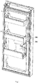
FIG. 1 is a structure schematic view of a door body of a refrigerator according to an embodiment of the present invention; -
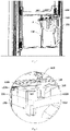
FIG. 2 is a cross-sectional view of an automatic water supply device according to an embodiment of the present invention; -
FIG. 3 is an enlarged view of portion A inFIG. 2 ; -
FIG. 4 is a cross-sectional view of an automatic water supply device according to an embodiment of the present invention; -
FIG. 5 is an enlarged view of portion B inFIG. 4 ; -
FIG. 6 is a structural schematic view of a water vessel in an embodiment of the present invention; -
FIG. 7 is a cross-sectional view of a water vessel in an embodiment of the present invention; -
FIG. 8 is a flow chart of an automatic water supply method according to an embodiment of the present invention; -
FIG. 9 is a flow chart of an automatic water supply method according to an embodiment of the present invention; -
FIG. 10 is a flow chart of an automatic water supply method according to an embodiment of the present invention. - Reference now will be made in detail to embodiments of the invention, one or more examples of which are illustrated in the drawings.Each example is provided by way of explanation of the invention, not limitation of the invention. In fact, it will be apparent to those skilled in the art that various modifications and variations can be made in the present invention without departing from the scope of the invention.For instance, features illustrated or described as part of one embodiment can be used with another embodiment to yield a still further embodiment.Thus, it is intended that the present invention covers such modifications and variations as come within the scope of the appended claims and their equivalents.
- As shown in
FIG. 1 , an embodiment of the present invention discloses a refrigerator. The refrigerator comprises a cabinet and adoor body 1 for opening and closing the cabinet, an automatic water supply device being provided on an inner side of thedoor body 1. As shown inFIGS. 2-7 , the automatic water supply device comprises awater vessel 100, abracket 200 for placing thewater vessel 100, a detection means 300, and awater supply mechanism 400 for supplying water to thewater vessel 100. The cabinet may define a refrigerating chamber. When thedoor body 1 closes the cabinet, the cold air in the refrigerating chamber may cool the water in thewater vessel 100. - Certainly, sites where the automatic water supply device is used are not limited to refrigerators, and may be various sites such as other refrigeration appliances or cafes. In embodiments of the present invention, water is a collective term of liquid beverages, and includes but not limited to liquid beverages such as purified water, fruit juice, milk or coffee.
- As shown in
FIGS. 3-7 , thewater vessel 100 comprises awater filling port 110. The detection means 300 comprises aninductive element 321 and afirst sensor 322 disposed on thebracket 200. Theinductive element 321 is disposed in thewater vessel 100 and capable of rising or falling along with the liquid level. Thefirst sensor 322 outputs a first detection signal upon detecting that theinductive element 321 is located at a first height. Thewater supply mechanism 400 comprises awater supply pipe 410 and a water valve provided on thewater supply pipe 410. An outlet of thewater supply pipe 410 corresponds to thewater filling port 110 of thewater vessel 100. The automatic water supply device further comprises a controller controlling the water valve to open upon receiving the first detection signal. The detection means further includes a detection element capable of outputting a second detection signal characterizing the liquid level in the water vessel, and the controller controls the water valve to close upon receiving the second detection signal. - In the automatic water supply device disclosed in the present invention, the controller will control the water valve to open only when the
first sensor 322 detects that theinductive element 321 is located at a low first height. If the user forgets to put the inductive element into the water vessel after cleaning the water vessel, the controller will always control the water valve to close, so that it will not automatically fill the water vessel with water. This avoids the problem of water overflow from the water vessel because the sensor cannot detect the inductive element and water is filled constantly. - Specifically, in the embodiment of the present invention, the detection element is a
second sensor 323 provided on thebracket 200, thesecond sensor 323 outputs the second detection signal upon detecting that theinductive element 321 is located at the second height, and the second height is greater than the first height. The second sensor 210 is used to determine the timing for stopping water filling after the water filling starts. - Specifically, the first height is closer to the bottom of the
water vessel 100 than the second height, that is, theinductive element 321 is at the lowest point in thewater vessel 100. It may be believed that when theinductive element 321 is at the first height, there is little or no water in thewater vessel 100, whereupon the water valve needs to be opened to fill water; the second height is a height closer to the top of thewater vessel 100. It may be appreciated that when theinductive element 321 is at the second height, thewater vessel 100 contains a large amount of water or is in a full state, whereupon the water valve needs to be closed to stop the water filling. When the liquid level in thewater vessel 100 is lower than the first height, the liquid level in thewater vessel 100 must be lower than or equal to the first height, and thefirst sensor 322 will detect the inductive element and output the first detection signal, and the controller will control the water valve to open to fill thewater vessel 100 with water. During the water filling process, theinductive element 321 will move upward with the liquid level, and when it reaches the second height, the liquid level in thewater vessel 100 also reaches the second height. At this time, thesecond sensor 323 will detect theinductive element 321 and output the second detection signal, the controller will control the water valve to close, thereby completing the process of automatic water filling. - Specifically, the
water supply pipe 410 may be externally connected to the user's water source, and extends along the cabinet of the refrigerator into thedoor body 1. When the water valve is opened, the external water source may fill thewater vessel 100 with water through thewater supply pipe 410. Specifically, in the embodiment of the present invention, the water supply pipe extends from a compressor compartment at a lower part of the cabinet along the cabinet into the inner side of the door body, and the water valve may be provided on the water supply pipe in the compressor compartment. Certainly, in other embodiments, the water valve may also be disposed on other parts of the water supply pipe. - As shown in
FIG. 3 , in the embodiment of the present invention, afloat box 131 is provided in the water vessel, theinductive element 321 is fixedly disposed in thefloat box 131, and thefloat box 131 rises and falls as the liquid level changes. Thefloat box 131 seals theinductive element 321 inside to ensure that it may float up and down. - Specifically, a side wall of the
water vessel 100 is provided with arail 132 extending in the height direction, thefloat box 131 is located in therail 132, and therail 132 is provided with awater hole 1323 through which water flows. Specifically, along the height direction of thewater vessel 100, an inner side wall of thewater vessel 100 is provided with therail 132. The rail includes ahousing 1321 protruding into the interior of the water vessel and aninternal channel 1322 surrounded by thehousing 1321. Thefloat box 131 is provided in theinternal channel 1322, and thewater hole 1323 communicated with theinternal channel 1322 is provided in the lengthwise direction of the side wall of thehousing 1321, so that the liquid in thewater vessel 100 may flow into theinternal channel 1322. The size of theinternal channel 1322 is adapted to the size of thefloat box 131 so that thefloat box 131 can only move in the vertical direction with the liquid level. In addition, the bottom wall of thehousing 1321 is also provided with a water hole to facilitate the liquid to enter theinternal channel 1322. The top of thehousing 1321 is provided with anopening 1324 and aseal 1325 for sealing theopening 1324. When the user cleans the water vessel, theseal 1325 may be taken out, and thefloat box 131 may also be taken out for cleaning. - In another embodiment, an inner box fixedly connected to the water vessel lid and extending downward from the lid may also be provided, and the float box is disposed inside the inner box so that the liquid in the water vessel may flow into the interior of the inner box such that the float may float up and down with the liquid level.
- In the embodiment of the present invention, as shown in
FIGS. 4-5 , thefirst sensor 322 and thesecond sensor 323 are both a Hall switch, and theinductive element 321 is a magnet. The two Hall switches are disposed on thebracket 200 in the height direction, and may respectively detect the approach of the magnet. Specifically, the Hall switch is an active electromagnetic conversion device fabricated by an integrated packaging and assembling process based on the principle of the Hall effect. The Hall switch may induce a magnitude of the magnetic flux. When the magnetic flux reaches a preset value, a trigger in the Hall switch flips, and an output level state of the Hall switch is also inverted accordingly, so that the magnetic input signal may be converted into an electrical signal. The magnet in the float box will move up and down along with the liquid level, and the magnetic flux detected by the Hall switch will also change accordingly. - The
first sensor 322 is disposed on thebracket 200 at a position corresponding to the first height, and thesecond sensor 323 is disposed on thebracket 200 at a position corresponding to the second height. After thewater vessel 100 is placed on thebracket 200, if the user forgets to put thefloat box 131 back into thewater vessel 100, thefirst sensor 322 can never detect theinductive element 321, and the water valve will remain closed and water will not be automatically filled into thewater vessel 100 regardless of whether there is water in thewater vessel 100. If thewater vessel 100 is placed on thebracket 200 and thefloat box 131 is in thewater vessel 100, the height of theinductive element 321 varies with the liquid level. If the liquid level in thewater vessel 100 is equal to or lower than the first height, theinductive element 321 is located at the first height. At this time, theinductive element 321 is the closest to thefirst sensor 322, the magnetic flux sensed by thefirst sensor 322 reaches a preset value, the trigger inside thefirst sensor 322 flips to cause the output level state of thefirst sensor 322 to switch (the Hall switch switches an ON state to an OFF state), and the controller receives the first detection signal and opens the water valve to automatically fill water into thewater vessel 100. During the water filling process, the liquid level will rise to drive thefloat box 131 to move upward, and theinductive element 321, namely, the magnet, will also approach thesecond sensor 323 until the liquid level in thewater vessel 100 reaches the second height. At this time, the magnetic flux sensed by thesecond sensor 323 also reaches the preset value, the trigger inside thesecond sensor 323 flips to cause the output level state of thesecond sensor 323 to switch (the Hall switch switches from the OFF state to the ON state), and the controller will receive the second detection signal and close the water valve to stop the automatic water filling. In this way, the position of the magnet is detected and the liquid level in the water vessel is judged through the two Hall switches, respectively, and the controller controls the water valve to open or close according to different detection signals sent by different Hall switches, to automatically fill water into the water vessel if necessary. Furthermore, setting the water valve to be opened only when the first detection signal indicating that the inductive element is at the first height is received can ensure that theinductive element 321 is already inside thewater vessel 100 at this time, and the problem of water overflow will not occur. - Similarly, the detection means 320 may also detect whether the
water vessel 100 is placed on thebracket 200. When the controller receives the first detection signal, it may be determined that thewater vessel 100 is already placed on thebracket 200 at this time, and the liquid level is low and water needs to be automatically filled. - In other embodiments, the second sensor may also be other sensors such as a photoelectric sensor, a capacitive liquid level sensor, etc., which is not limited in the present invention. A sensor such as a photoelectric sensor or a capacitive liquid level sensor may directly detect the liquid level in the water vessel. When the real-time liquid level reaches a preset liquid level, it will trigger the aforementioned sensor to output a detection signal to the controller to cause the controller to close the water valve.
- In another embodiment, the detection element may also be a timer, and the first sensor may be a Hall switch. During the water filling process, the inductive element will gradually move upwards with the liquid level, and the magnetic flux sensed by the first sensor will be less than the preset value at a certain liquid level, the output level state of the first sensor will switch again (the Hall switch switches from the ON state to the OFF state), and the controller will receive an OFF signal output by the first sensor and control the timer to start timing. When the water filling time reaches a preset time (which may be 15s, 30s, or the like), the controller may control to close the water valve. Thus, the second sensor may be omitted, and only the first sensor may be used to cooperate with the inductive element and the timer to control the opening and closing of the water valve and the automatic water filling process. Specifically, the preset time may be calculated in advance according to the height of the first sensor, the speed of automatic water filling and the volume of the water vessel.
- As shown in
FIGS. 6-7 , thewater vessel 100 further comprises awater vessel lid 120, awater vessel body 130, and a water storage space defined by thewater vessel lid 120 and thewater vessel body 130. Thewater filling port 110 is disposed on thewater vessel lid 120. Thewater vessel 100 further comprises awater filling cup 140 extending from thewater filling port 110 to the bottom of thewater vessel 100. A plurality of water outlets 141 communicated with the water storage space are provided on a peripheral wall of thewater filling cup 140. Thewater filling cup 140 may slow down the flow rate of the water upon water filling, reduce the noise upon water filling, and prevent the water flow from splashing around. - Preferably, the
water filling cup 140 comprises an upwardly-protrudingbottom wall 142, and the water outlets 141 extend from top to bottom on the peripheral wall to a position connected to thebottom wall 142. Specifically, a plurality of elongated water outlets 141 are provided at an interval on the peripheral wall of thewater filling cup 140, and the water outlets 141 extend on the peripheral wall of thewater filling cup 140 so that water can flow into the water storage space quickly without gathering in thewater filling cup 140. The upward protrusion of thebottom wall 142 may further prevent the water in thewater filling cup 140 from gathering and enable the water to flow out through the water outlets 141. - A
water spout 131 is disposed on thewater vessel body 130, awater baffle 150 is provided at a position adjacent to thewater spout 131 in the water storage space, and awater passageway 151 communicated with thewater spout 131 is formed between thewater baffle 150 and the inner wall of thewater vessel 100. When the user takes water, he may pour out water through thewater spout 131. Thewater baffle 150 is provided to prevent the water from flowing rapidly and splashing out of thewater vessel 100 when the user pours water. - Preferably, the
water baffle 150 is preferably arc-shaped. Furthermore, the arc top of thewater baffle 150 protrudes toward the side wall of thewater vessel 100 opposite to thewater spout 131. The arc-shapedwater baffle 150 has a good water blocking effect, and its arc top protrudes toward the side wall of thewater vessel 100 opposite to thewater spout 131, so that an effective water passageway is formed between thewater baffle 150 and the side wall of thewater vessel 100, and further enhances the splash-preventing effect. - In the embodiment of the present invention, the
water baffle 150 extends from thewater vessel lid 120 to the bottom of thewater vessel 100, and thewater passageway 151 is formed on both sides and the bottom of thewater baffle 150. Thewater baffle 150 extending to the bottom of thewater vessel 100 may guide water into the water passageway from a lower position of thewater vessel 100, thereby further reducing the flow rate of water when poured. - As shown in
FIG. 1 , thedoor 1 is provided with abottle seat 3, and thebracket 200 is additionally disposed on thebottle seat 3. Thebracket 200 is pre-assembled with thebottle seat 3 through a connecting piece. The connecting piece may be specifically a hook structure to facilitate mounting thebracket 200 to or demounting thebracket 200 from thebottle seat 3. When the user does not need to use the water vessel, he may remove thewater vessel 100 and thebracket 200, and the original position where the bracket is placed may continue to serve as the bottle seat. The outlet of thewater supply pipe 410 is fixed at an upper half of thebracket 100 to align with thewater filling port 110 on thewater vessel lid 120 of thewater vessel 100. Thewater vessel 100 is located below thebottle seat 3 and on a side close to the door handle. Thewater vessel 100 may be drawn out transversely along the width direction of the door body, so it occupies a small space in the refrigerator without affecting the storage space of the shelves in the refrigerating compartment. - As shown in
FIGS. 8-10 , another aspect of the present invention discloses an automatic water supply method for supplying water to a water vessel disposed on a refrigerator door, the method comprising: - S 100: detecting a real-time height of the
inductive element 321 provided in thewater vessel 100. - In the embodiment of the present invention, the
inductive element 321 is mounted in thefloat box 131 and may move up and down with the liquid level. Specifically, thefirst sensor 322 disposed on the bracket is used to detect the real-time height of the inductive element. Thefirst sensor 322 is a Hall switch, and theinductive element 321 is a magnet. - S200: outputting a first detection signal when the
inductive element 321 is located at a first height. - When the
inductive element 321 is located at the first height and closest to thefirst sensor 322, the magnetic flux sensed by thefirst sensor 322 reaches a preset value and makes a trigger in thefirst sensor 322 flip so that thefirst sensor 322 outputs the first detection signal to the controller. - S300: the controller opens the water valve upon receiving the first detection signal.
- When the controller receives the first detection signal, this means that the liquid level in the
water vessel 100 is low at this time and water needs to be filled, and then the controller will open the water valve. - S400: the controller closes the water valve upon receiving a second detection signal.
- The second detection signal is a signal output by the
second sensor 323 provided on thebracket 200. Thesecond sensor 323 may detect the liquid level in thewater vessel 100. When the liquid level reaches the preset liquid level, the water in the water vessel is already enough and the water filling may be stopped. Therefore, thesecond sensor 323 outputs a second detection signal, and the controller closes the water valve upon receiving the second detection signal. - Further, as shown in
FIG. 9 , after step S300, the method further comprises: - S310: When the
inductive element 321 is located at a second height, output the second detection signal, the second height being greater than the first height. - In the embodiment of the present invention, the
second sensor 323 is a Hall switch, and its height is higher than that of thefirst sensor 322. Therefore, when theinductive element 321 is close to thesecond sensor 323, the magnetic flux sensed by thesecond sensor 323 reaches the preset value and makes the trigger inside thesecond sensor 323 flip, so that thesecond sensor 323 outputs the second detection signal to the controller. - Further, the method further comprises:
- S500: the controller closes the water valve upon receiving a water overflow signal or a refrigerator door opening signal.
- The automatic water supply device is further provided with an overflow detection means and a refrigerator door opening and closing detection means. The overflow detection means is configured to detect whether the water in the water vessel overflows. The refrigerator door opening and closing means is configured to detect whether the refrigerator door is in an open state or a closed state. Specifically, if the controller receives the overflow signal, it means that the water in the water vessel is already full, so the controller needs to close the water valve. If the controller receives the refrigerator door opening signal, the user might take out the water vessel, whereupon water filling needn't be continued, so the controller also needs to close the water valve.
- Further, as shown in
FIG. 10 , after the step S300, the method further comprises: - S320: A timer records an opening time period of the water valve.
- After the controller opens the water valve, the timer will start to record the opening time period of the water valve.
- S321: When the opening time period exceeds a preset time period, the timer outputs a timeout signal.
- Generally speaking, the flow rate of filled water is constant. An amount of the filled water may be calculated by multiplying the flow rate by a water filing time period. In order to prevent the failure of the detection means and the overflow detection means, the automatic water supply device is further provided with water filling timeout protection. When the water filling time period exceeds a preset time period, overflow phenomenon might occur, and the timer will output a timeout signal to the controller. Specifically, a specific value of the preset time period may be designed based on parameters such as the flow rate of filled water, the volume of the water vessel, and the like. In the embodiment of the present invention, the preset time period may be set to 150 seconds.
- S322: the controller closes the water valve upon receiving the timeout signal.
- When the controller receives the timeout signal which indicates that water overflow might occur, the controller will close the water valve to avoid excessive water overflow.
- In the automatic water supply device disclosed in the present invention, the controller will control the water valve to open only when the first sensor detects that the inductive element is at a lower first height. If the user forgets to put the inductive element into the water vessel after cleaning the water vessel, the controller will keep the water valve closed, so that water will not be automatically filled into the water vessel, thereby avoiding the problem of water overflow out of the water vessel caused by continued water filling because the sensor fails to detect the inductive element. Two Hall switches and a magnet are used to detect the liquid level in the water vessel, so that the structure is simple and the detection accuracy is high. With the rail disposed on the inner wall of the water vessel and the float box being disposed in the rail, the magnet may be enabled to move up and down with the liquid level, and output different detection signals by approaching different Hall switches. The controller may control the opening and closing of the water valve according to the received different detection signals. The water filling cup disposed in the water vessel may slow down the flow rate of the water upon water filling, reduce the noise upon water filling, and prevent the water flow from splashing around. The upward protrusion of the bottom wall of the water filling cup may further prevent the water in the water filling cup from gathering and enable the water to flow out through the water outlets. The water baffle may be provided to prevent the water from flowing rapidly and splashing out of the water vessel when the user pours water.
- This written description uses examples to disclose the invention, including the best mode, and also to enable any person skilled in the art to practice the invention, including making and using any devices or systems and performing any incorporated methods.The patentable scope of the invention is defined by the claims, and may include other examples that occur to those skilled in the art.Such other examples are intended to be within the scope of the claims if they include structural elements that do not differ from the literal language of the claims, or if they include equivalent structural elements with insubstantial differences from the literal languages of the claims.
Claims (15)
- An automatic water supply device, wherein the device comprises a water vessel, a bracket for placing the water vessel, a detection means, and a water supply mechanism for supplying water to the water vessel, the water vessel comprising a water filling port;the detection means comprises an inductive element and a first sensor disposed on the bracket, the inductive element is disposed in the water vessel and capable of rising or falling along with the liquid level, and the first sensor outputs a first detection signal upon detecting that the inductive element is located at a first height;the water supply mechanism comprises a water supply pipe and a water valve provided on the water supply pipe, and an outlet of the water supply pipe corresponds to the water filling port of the water vessel;the automatic water supply device further comprises a controller controlling the water valve to open upon receiving the first detection signal;the detection means further comprises a detection element capable of outputting a second detection signal characterizing the liquid level in the water vessel, and the controller controls the water valve to close upon receiving the second detection signal.
- The automatic water supply device according to claim 1, wherein the detection element is a second sensor provided on the bracket, the second sensor outputs the second detection signal upon detecting that the inductive element is located at a second height, and the second height is greater than the first height.
- The automatic water supply device according to claim 2, wherein the first sensor and the second sensor are both a Hall switch, and the inductive element is a magnet.
- The automatic water supply device according to claim 1, wherein a float box is provided in the water vessel, the inductive element is fixedly disposed in the float box, and the float box rises and falls as the liquid level changes.
- The automatic water supply device according to claim 4, wherein a side wall of the water vessel is provided with a rail extending in a height direction, the float box is located in the rail, and the rail is provided with a water hole through which water flows.
- The automatic water supply device according to claim 1, wherein the water vessel further comprises a water vessel lid, a water vessel body, and a water storage space defined by the water vessel lid and the water vessel body, and the water filling port is disposed on the water vessel lid; the water vessel further comprises a water filling cup extending from the water filling port to the bottom of the water vessel, and a plurality of water outlets communicated with the water storage space are provided on a peripheral wall of the water filling cup.
- The automatic water supply device according to claim 6, wherein the water filling cup comprises an upwardly-protruding bottom wall, and the water outlets extend from top to bottom on the peripheral wall to a position connected to the bottom wall.
- The automatic water supply device according to claim 1, wherein the water vessel further comprises a water vessel lid, a water vessel body, and a water storage space defined by the water vessel lid and the water vessel body, a water spout is disposed on the water vessel body, a water baffle is provided at a position adjacent to the water spout in the water storage space, and a water passageway communicated with the water spout is formed between the water baffle and the inner wall of the water vessel.
- The automatic water supply device according to claim 8, wherein the water baffle is arc-shaped.
- The automatic water supply device according to claim 8, wherein the water baffle extends from the water vessel lid to the bottom of the water vessel, and the water passageway is formed on both sides and the bottom of the water baffle.
- A refrigerator, wherein the refrigerator comprises a cabinet and a door body for opening and closing the cabinet, the water supply device according to any of claims 1-10 being disposed on an inner side of the door body.
- An automatic water supply method for supplying water to a water vessel disposed on a refrigerator door, wherein the method comprises:detecting a real-time height of an inductive element provided in the water vessel;outputting a first detection signal when the inductive element is located at a first height;the controller opening a water valve upon receiving the first detection signal;the controller closing the water valve upon receiving a second detection signal.
- The automatic water supply method according to claim 12, wherein the method further comprises:
when the inductive element is located at a second height, outputting the second detection signal, the second height being greater than the first height. - The automatic water supply method according to claim 12, wherein the method further comprises:
the controller closing the water valve upon receiving a water overflow signal or a refrigerator door opening signal. - The automatic water supply method according to claim 12, wherein after the step "the controller opening a water valve upon receiving the first detection signal", the method further comprises:a timer records an opening time period of the water valve;when the opening time period exceeds a first preset time period, the timer outputs a first timeout signal;the controller closes the water valve upon receiving the first timeout signal.
Applications Claiming Priority (2)
| Application Number | Priority Date | Filing Date | Title |
|---|---|---|---|
| CN202010183459.5A CN113405311A (en) | 2020-03-16 | 2020-03-16 | Automatic water supply device, refrigerator with same and automatic water supply method |
| PCT/CN2020/115643 WO2021184711A1 (en) | 2020-03-16 | 2020-09-16 | Automatic water supply device, refrigerator having same and automatic water supply method |
Publications (3)
| Publication Number | Publication Date |
|---|---|
| EP4123250A1 true EP4123250A1 (en) | 2023-01-25 |
| EP4123250A4 EP4123250A4 (en) | 2023-08-09 |
| EP4123250B1 EP4123250B1 (en) | 2025-08-20 |
Family
ID=77676619
Family Applications (1)
| Application Number | Title | Priority Date | Filing Date |
|---|---|---|---|
| EP20925224.6A Active EP4123250B1 (en) | 2020-03-16 | 2020-09-16 | Automatic water supply device, refrigerator having same |
Country Status (4)
| Country | Link |
|---|---|
| EP (1) | EP4123250B1 (en) |
| CN (1) | CN113405311A (en) |
| AU (1) | AU2020436861B2 (en) |
| WO (1) | WO2021184711A1 (en) |
Families Citing this family (5)
| Publication number | Priority date | Publication date | Assignee | Title |
|---|---|---|---|---|
| CN116928965B (en) * | 2022-03-29 | 2026-05-12 | 青岛海尔电冰箱有限公司 | Method for preparing cooling water and refrigerator |
| US11780722B1 (en) * | 2022-10-14 | 2023-10-10 | Haier Us Appliance Solutions, Inc. | Autofill pitcher overfill shutoff mechanism |
| WO2024146618A1 (en) * | 2023-01-05 | 2024-07-11 | 海尔智家股份有限公司 | Automatic water filling water jug capable of carrying out overflow control by means of flow meter |
| CN119197023A (en) * | 2023-06-26 | 2024-12-27 | 青岛海尔电冰箱有限公司 | Refrigerator control method, storage medium and refrigerator |
| CN119393954B (en) * | 2024-11-04 | 2026-04-03 | 合肥美的电冰箱有限公司 | Refrigerator assembly |
Family Cites Families (20)
| Publication number | Priority date | Publication date | Assignee | Title |
|---|---|---|---|---|
| GB1223980A (en) * | 1967-01-31 | 1971-03-03 | Bulpitt & Sons Ltd | Improvements in kettles |
| GB2268680B (en) * | 1991-11-05 | 1994-06-29 | Strix Ltd | Water heating jugs |
| JP2526984Y2 (en) * | 1992-03-05 | 1997-02-26 | テン ティン−ソウ | Teapot to taste the tea |
| JPH09218079A (en) * | 1996-02-08 | 1997-08-19 | Miyaken Kogyo Kk | Water level sensor |
| CN2896151Y (en) * | 2006-01-11 | 2007-05-02 | 博罗耀峰电子有限公司 | Automatic water supply device of household ice maker |
| US9474249B2 (en) * | 2011-09-06 | 2016-10-25 | Pioneer Pet Products, Llc | Recirculating pet fountain |
| US9890029B2 (en) * | 2011-12-09 | 2018-02-13 | Electrolux Home Products, Inc. | Refrigerator with automatic liquid dispenser |
| CN202960094U (en) * | 2012-12-11 | 2013-06-05 | 广东格兰仕集团有限公司 | Electric kettle |
| GB2517485A (en) * | 2013-08-22 | 2015-02-25 | Otter Controls Ltd | Appliances and components therefor |
| CN104180600B (en) * | 2014-09-10 | 2017-05-31 | 合肥晶弘电器有限公司 | The refrigerator water path control system and refrigerator of a kind of automatic circulation water-supplying |
| CN105806025B (en) * | 2014-12-31 | 2019-07-02 | 青岛海尔股份有限公司 | Water supply device and refrigerator having the same |
| CN106766657A (en) * | 2016-12-27 | 2017-05-31 | 青岛海尔股份有限公司 | The refrigerator water path control system and the refrigerator with it of a kind of automatic water-supply |
| CN206407985U (en) * | 2016-12-29 | 2017-08-15 | 芬雷选煤工程技术(北京)有限公司 | A kind of softening water tank of automatic water-supply |
| WO2018140680A1 (en) * | 2017-01-30 | 2018-08-02 | Electrolux Home Products, Inc. | Refrigerator with automatic liquid dispenser |
| CN207122893U (en) * | 2017-07-03 | 2018-03-20 | 福建龙岩喜鹊纺织有限公司 | A kind of boiler automatic water inlet system |
| CN206499341U (en) * | 2017-07-18 | 2017-09-19 | 厦门越一电子科技有限公司 | A kind of water boiling device for exempting from out pot lid |
| CN108903664B (en) * | 2018-07-05 | 2021-07-20 | 华南理工大学 | An image processing-based method for detecting the liquid level of a drinking cup in a water dispenser |
| CN209398960U (en) * | 2019-01-07 | 2019-09-17 | 贵州同益新型建材有限公司 | A kind of inside spin extrusion type hollow spiral hush pipe |
| CN209655551U (en) * | 2019-03-20 | 2019-11-19 | 浙江绍兴苏泊尔生活电器有限公司 | Rapid Heat Liquid Heating Vessels |
| CN212205300U (en) * | 2020-03-16 | 2020-12-22 | 青岛海尔电冰箱有限公司 | Automatic water supply device and refrigerator with same |
-
2020
- 2020-03-16 CN CN202010183459.5A patent/CN113405311A/en active Pending
- 2020-09-16 AU AU2020436861A patent/AU2020436861B2/en active Active
- 2020-09-16 EP EP20925224.6A patent/EP4123250B1/en active Active
- 2020-09-16 WO PCT/CN2020/115643 patent/WO2021184711A1/en not_active Ceased
Also Published As
| Publication number | Publication date |
|---|---|
| AU2020436861A1 (en) | 2022-10-13 |
| AU2020436861B2 (en) | 2023-12-07 |
| EP4123250B1 (en) | 2025-08-20 |
| WO2021184711A1 (en) | 2021-09-23 |
| CN113405311A (en) | 2021-09-17 |
| EP4123250A4 (en) | 2023-08-09 |
Similar Documents
| Publication | Publication Date | Title |
|---|---|---|
| EP4123250B1 (en) | Automatic water supply device, refrigerator having same | |
| CN212205300U (en) | Automatic water supply device and refrigerator with same | |
| EP4123249B1 (en) | Automatic water supply device and refrigerator having the same | |
| CN212205301U (en) | Water supply device and refrigerator with same | |
| KR0160414B1 (en) | Auto drink supplement equipment of water dispenser for a refrigerator | |
| US8613203B2 (en) | Refrigerator and control method thereof | |
| EP4123248B1 (en) | Automatic water supply device and refrigerator having the same | |
| EP3674637A1 (en) | Refrigerating appliance | |
| US8746296B2 (en) | Refrigerator appliance with features for assisted dispensing | |
| US20150197417A1 (en) | Self-filling refrigerator water pitcher | |
| US20130000337A1 (en) | Method and system for dispensing ice and/or a liquid | |
| WO2024078572A1 (en) | Over-filling closing mechanism of automatic filling kettle | |
| CN105806025B (en) | Water supply device and refrigerator having the same | |
| US20250311878A1 (en) | Refrigerator liquid brewing and storage system | |
| CN105795908B (en) | Automatic water supply method of water supply device | |
| EP4733693A1 (en) | Refrigeration appliance | |
| CN224140606U (en) | Automatic beverage filling machine capable of stopping when full of cup | |
| KR200390952Y1 (en) | Hot and cold clean water device with coffee dispenser | |
| KR20200087242A (en) | Water server and water supply method to water server | |
| KR200322785Y1 (en) | A dispenser for refrigerators with means for discharging remamining water | |
| US20260083274A1 (en) | Beverage machine | |
| WO2024146618A1 (en) | Automatic water filling water jug capable of carrying out overflow control by means of flow meter | |
| KR200411677Y1 (en) | Plastic Bottle Cork | |
| JPS6012224Y2 (en) | Beverage vending machine waste liquid treatment equipment | |
| KR200390951Y1 (en) | Hot and cold clean water device with coffee dispenser |
Legal Events
| Date | Code | Title | Description |
|---|---|---|---|
| STAA | Information on the status of an ep patent application or granted ep patent |
Free format text: STATUS: THE INTERNATIONAL PUBLICATION HAS BEEN MADE |
|
| PUAI | Public reference made under article 153(3) epc to a published international application that has entered the european phase |
Free format text: ORIGINAL CODE: 0009012 |
|
| STAA | Information on the status of an ep patent application or granted ep patent |
Free format text: STATUS: REQUEST FOR EXAMINATION WAS MADE |
|
| 17P | Request for examination filed |
Effective date: 20220331 |
|
| AK | Designated contracting states |
Kind code of ref document: A1 Designated state(s): AL AT BE BG CH CY CZ DE DK EE ES FI FR GB GR HR HU IE IS IT LI LT LU LV MC MK MT NL NO PL PT RO RS SE SI SK SM TR |
|
| DAV | Request for validation of the european patent (deleted) | ||
| DAX | Request for extension of the european patent (deleted) | ||
| A4 | Supplementary search report drawn up and despatched |
Effective date: 20230711 |
|
| RIC1 | Information provided on ipc code assigned before grant |
Ipc: F25D 23/12 20060101ALI20230705BHEP Ipc: F25D 29/00 20060101AFI20230705BHEP |
|
| GRAP | Despatch of communication of intention to grant a patent |
Free format text: ORIGINAL CODE: EPIDOSNIGR1 |
|
| STAA | Information on the status of an ep patent application or granted ep patent |
Free format text: STATUS: GRANT OF PATENT IS INTENDED |
|
| INTG | Intention to grant announced |
Effective date: 20250326 |
|
| GRAS | Grant fee paid |
Free format text: ORIGINAL CODE: EPIDOSNIGR3 |
|
| GRAA | (expected) grant |
Free format text: ORIGINAL CODE: 0009210 |
|
| STAA | Information on the status of an ep patent application or granted ep patent |
Free format text: STATUS: THE PATENT HAS BEEN GRANTED |
|
| RAP3 | Party data changed (applicant data changed or rights of an application transferred) |
Owner name: QINGDAO HAIER REFRIGERATOR CO., LTD Owner name: HAIER SMART HOME CO., LTD. |
|
| AK | Designated contracting states |
Kind code of ref document: B1 Designated state(s): AL AT BE BG CH CY CZ DE DK EE ES FI FR GB GR HR HU IE IS IT LI LT LU LV MC MK MT NL NO PL PT RO RS SE SI SK SM TR |
|
| REG | Reference to a national code |
Ref country code: GB Ref legal event code: FG4D |
|
| REG | Reference to a national code |
Ref country code: CH Ref legal event code: EP |
|
| REG | Reference to a national code |
Ref country code: IE Ref legal event code: FG4D |
|
| REG | Reference to a national code |
Ref country code: DE Ref legal event code: R096 Ref document number: 602020057209 Country of ref document: DE |
|
| PGFP | Annual fee paid to national office [announced via postgrant information from national office to epo] |
Ref country code: DE Payment date: 20250916 Year of fee payment: 6 |
|
| PGFP | Annual fee paid to national office [announced via postgrant information from national office to epo] |
Ref country code: GB Payment date: 20250919 Year of fee payment: 6 |
|
| PGFP | Annual fee paid to national office [announced via postgrant information from national office to epo] |
Ref country code: FR Payment date: 20250929 Year of fee payment: 6 |
|
| REG | Reference to a national code |
Ref country code: NL Ref legal event code: MP Effective date: 20250820 |
|
| PG25 | Lapsed in a contracting state [announced via postgrant information from national office to epo] |
Ref country code: IS Free format text: LAPSE BECAUSE OF FAILURE TO SUBMIT A TRANSLATION OF THE DESCRIPTION OR TO PAY THE FEE WITHIN THE PRESCRIBED TIME-LIMIT Effective date: 20251220 |
|
| PG25 | Lapsed in a contracting state [announced via postgrant information from national office to epo] |
Ref country code: NO Free format text: LAPSE BECAUSE OF FAILURE TO SUBMIT A TRANSLATION OF THE DESCRIPTION OR TO PAY THE FEE WITHIN THE PRESCRIBED TIME-LIMIT Effective date: 20251120 |
|
| REG | Reference to a national code |
Ref country code: LT Ref legal event code: MG9D |
|
| PG25 | Lapsed in a contracting state [announced via postgrant information from national office to epo] |
Ref country code: PT Free format text: LAPSE BECAUSE OF FAILURE TO SUBMIT A TRANSLATION OF THE DESCRIPTION OR TO PAY THE FEE WITHIN THE PRESCRIBED TIME-LIMIT Effective date: 20251222 |
|
| PG25 | Lapsed in a contracting state [announced via postgrant information from national office to epo] |
Ref country code: FI Free format text: LAPSE BECAUSE OF FAILURE TO SUBMIT A TRANSLATION OF THE DESCRIPTION OR TO PAY THE FEE WITHIN THE PRESCRIBED TIME-LIMIT Effective date: 20250820 |
|
| PG25 | Lapsed in a contracting state [announced via postgrant information from national office to epo] |
Ref country code: HR Free format text: LAPSE BECAUSE OF FAILURE TO SUBMIT A TRANSLATION OF THE DESCRIPTION OR TO PAY THE FEE WITHIN THE PRESCRIBED TIME-LIMIT Effective date: 20250820 Ref country code: NL Free format text: LAPSE BECAUSE OF FAILURE TO SUBMIT A TRANSLATION OF THE DESCRIPTION OR TO PAY THE FEE WITHIN THE PRESCRIBED TIME-LIMIT Effective date: 20250820 |
|
| PG25 | Lapsed in a contracting state [announced via postgrant information from national office to epo] |
Ref country code: GR Free format text: LAPSE BECAUSE OF FAILURE TO SUBMIT A TRANSLATION OF THE DESCRIPTION OR TO PAY THE FEE WITHIN THE PRESCRIBED TIME-LIMIT Effective date: 20251121 |
|
| PG25 | Lapsed in a contracting state [announced via postgrant information from national office to epo] |
Ref country code: SE Free format text: LAPSE BECAUSE OF FAILURE TO SUBMIT A TRANSLATION OF THE DESCRIPTION OR TO PAY THE FEE WITHIN THE PRESCRIBED TIME-LIMIT Effective date: 20250820 |
|
| PG25 | Lapsed in a contracting state [announced via postgrant information from national office to epo] |
Ref country code: LV Free format text: LAPSE BECAUSE OF FAILURE TO SUBMIT A TRANSLATION OF THE DESCRIPTION OR TO PAY THE FEE WITHIN THE PRESCRIBED TIME-LIMIT Effective date: 20250820 |
|
| PG25 | Lapsed in a contracting state [announced via postgrant information from national office to epo] |
Ref country code: BG Free format text: LAPSE BECAUSE OF FAILURE TO SUBMIT A TRANSLATION OF THE DESCRIPTION OR TO PAY THE FEE WITHIN THE PRESCRIBED TIME-LIMIT Effective date: 20250820 Ref country code: PL Free format text: LAPSE BECAUSE OF FAILURE TO SUBMIT A TRANSLATION OF THE DESCRIPTION OR TO PAY THE FEE WITHIN THE PRESCRIBED TIME-LIMIT Effective date: 20250820 |
|
| PG25 | Lapsed in a contracting state [announced via postgrant information from national office to epo] |
Ref country code: RS Free format text: LAPSE BECAUSE OF FAILURE TO SUBMIT A TRANSLATION OF THE DESCRIPTION OR TO PAY THE FEE WITHIN THE PRESCRIBED TIME-LIMIT Effective date: 20251120 |
|
| PG25 | Lapsed in a contracting state [announced via postgrant information from national office to epo] |
Ref country code: ES Free format text: LAPSE BECAUSE OF FAILURE TO SUBMIT A TRANSLATION OF THE DESCRIPTION OR TO PAY THE FEE WITHIN THE PRESCRIBED TIME-LIMIT Effective date: 20250820 |
|
| REG | Reference to a national code |
Ref country code: AT Ref legal event code: MK05 Ref document number: 1827689 Country of ref document: AT Kind code of ref document: T Effective date: 20250820 |
|
| PG25 | Lapsed in a contracting state [announced via postgrant information from national office to epo] |
Ref country code: RO Free format text: LAPSE BECAUSE OF FAILURE TO SUBMIT A TRANSLATION OF THE DESCRIPTION OR TO PAY THE FEE WITHIN THE PRESCRIBED TIME-LIMIT Effective date: 20250820 |
|
| PG25 | Lapsed in a contracting state [announced via postgrant information from national office to epo] |
Ref country code: SM Free format text: LAPSE BECAUSE OF FAILURE TO SUBMIT A TRANSLATION OF THE DESCRIPTION OR TO PAY THE FEE WITHIN THE PRESCRIBED TIME-LIMIT Effective date: 20250820 |
|
| PG25 | Lapsed in a contracting state [announced via postgrant information from national office to epo] |
Ref country code: DK Free format text: LAPSE BECAUSE OF FAILURE TO SUBMIT A TRANSLATION OF THE DESCRIPTION OR TO PAY THE FEE WITHIN THE PRESCRIBED TIME-LIMIT Effective date: 20250820 |
|
| PG25 | Lapsed in a contracting state [announced via postgrant information from national office to epo] |
Ref country code: AT Free format text: LAPSE BECAUSE OF FAILURE TO SUBMIT A TRANSLATION OF THE DESCRIPTION OR TO PAY THE FEE WITHIN THE PRESCRIBED TIME-LIMIT Effective date: 20250820 |
|
| PG25 | Lapsed in a contracting state [announced via postgrant information from national office to epo] |
Ref country code: IT Free format text: LAPSE BECAUSE OF FAILURE TO SUBMIT A TRANSLATION OF THE DESCRIPTION OR TO PAY THE FEE WITHIN THE PRESCRIBED TIME-LIMIT Effective date: 20250820 |
|
| PG25 | Lapsed in a contracting state [announced via postgrant information from national office to epo] |
Ref country code: CZ Free format text: LAPSE BECAUSE OF FAILURE TO SUBMIT A TRANSLATION OF THE DESCRIPTION OR TO PAY THE FEE WITHIN THE PRESCRIBED TIME-LIMIT Effective date: 20250820 |
|
| PG25 | Lapsed in a contracting state [announced via postgrant information from national office to epo] |
Ref country code: EE Free format text: LAPSE BECAUSE OF FAILURE TO SUBMIT A TRANSLATION OF THE DESCRIPTION OR TO PAY THE FEE WITHIN THE PRESCRIBED TIME-LIMIT Effective date: 20250820 Ref country code: SK Free format text: LAPSE BECAUSE OF FAILURE TO SUBMIT A TRANSLATION OF THE DESCRIPTION OR TO PAY THE FEE WITHIN THE PRESCRIBED TIME-LIMIT Effective date: 20250820 |
|
| REG | Reference to a national code |
Ref country code: CH Ref legal event code: H13 Free format text: ST27 STATUS EVENT CODE: U-0-0-H10-H13 (AS PROVIDED BY THE NATIONAL OFFICE) Effective date: 20260504 |
|
| PG25 | Lapsed in a contracting state [announced via postgrant information from national office to epo] |
Ref country code: LU Free format text: LAPSE BECAUSE OF NON-PAYMENT OF DUE FEES Effective date: 20250916 |
|
| REG | Reference to a national code |
Ref country code: DE Ref legal event code: R097 Ref document number: 602020057209 Country of ref document: DE |
|
| REG | Reference to a national code |
Ref country code: BE Ref legal event code: MM Effective date: 20250930 |
|
| PLBE | No opposition filed within time limit |
Free format text: ORIGINAL CODE: 0009261 |
|
| STAA | Information on the status of an ep patent application or granted ep patent |
Free format text: STATUS: NO OPPOSITION FILED WITHIN TIME LIMIT |
|
| PG25 | Lapsed in a contracting state [announced via postgrant information from national office to epo] |
Ref country code: MC Free format text: LAPSE BECAUSE OF FAILURE TO SUBMIT A TRANSLATION OF THE DESCRIPTION OR TO PAY THE FEE WITHIN THE PRESCRIBED TIME-LIMIT Effective date: 20250820 Ref country code: LT Free format text: LAPSE BECAUSE OF FAILURE TO SUBMIT A TRANSLATION OF THE DESCRIPTION OR TO PAY THE FEE WITHIN THE PRESCRIBED TIME-LIMIT Effective date: 20250820 |
|
| REG | Reference to a national code |
Ref country code: CH Ref legal event code: L10 Free format text: ST27 STATUS EVENT CODE: U-0-0-L10-L00 (AS PROVIDED BY THE NATIONAL OFFICE) Effective date: 20260701 |
|
| PG25 | Lapsed in a contracting state [announced via postgrant information from national office to epo] |
Ref country code: CH Free format text: LAPSE BECAUSE OF NON-PAYMENT OF DUE FEES Effective date: 20250930 Ref country code: IE Free format text: LAPSE BECAUSE OF NON-PAYMENT OF DUE FEES Effective date: 20250916 Ref country code: BE Free format text: LAPSE BECAUSE OF NON-PAYMENT OF DUE FEES Effective date: 20250930 |
|
| 26N | No opposition filed |
Effective date: 20260521 |