EP4123213A1 - Hydrogen filling method, hydrogen filling apparatus, program, and record medium - Google Patents
Hydrogen filling method, hydrogen filling apparatus, program, and record medium Download PDFInfo
- Publication number
- EP4123213A1 EP4123213A1 EP22182978.1A EP22182978A EP4123213A1 EP 4123213 A1 EP4123213 A1 EP 4123213A1 EP 22182978 A EP22182978 A EP 22182978A EP 4123213 A1 EP4123213 A1 EP 4123213A1
- Authority
- EP
- European Patent Office
- Prior art keywords
- receptacle
- hydrogen
- nozzle
- flow
- filling
- Prior art date
- Legal status (The legal status is an assumption and is not a legal conclusion. Google has not performed a legal analysis and makes no representation as to the accuracy of the status listed.)
- Granted
Links
Images


Classifications
-
- F—MECHANICAL ENGINEERING; LIGHTING; HEATING; WEAPONS; BLASTING
- F17—STORING OR DISTRIBUTING GASES OR LIQUIDS
- F17C—VESSELS FOR CONTAINING OR STORING COMPRESSED, LIQUEFIED OR SOLIDIFIED GASES; FIXED-CAPACITY GAS-HOLDERS; FILLING VESSELS WITH, OR DISCHARGING FROM VESSELS, COMPRESSED, LIQUEFIED, OR SOLIDIFIED GASES
- F17C5/00—Methods or apparatus for filling containers with liquefied, solidified, or compressed gases under pressures
- F17C5/002—Automated filling apparatus
-
- F—MECHANICAL ENGINEERING; LIGHTING; HEATING; WEAPONS; BLASTING
- F17—STORING OR DISTRIBUTING GASES OR LIQUIDS
- F17C—VESSELS FOR CONTAINING OR STORING COMPRESSED, LIQUEFIED OR SOLIDIFIED GASES; FIXED-CAPACITY GAS-HOLDERS; FILLING VESSELS WITH, OR DISCHARGING FROM VESSELS, COMPRESSED, LIQUEFIED, OR SOLIDIFIED GASES
- F17C5/00—Methods or apparatus for filling containers with liquefied, solidified, or compressed gases under pressures
- F17C5/002—Automated filling apparatus
- F17C5/007—Automated filling apparatus for individual gas tanks or containers, e.g. in vehicles
-
- F—MECHANICAL ENGINEERING; LIGHTING; HEATING; WEAPONS; BLASTING
- F17—STORING OR DISTRIBUTING GASES OR LIQUIDS
- F17C—VESSELS FOR CONTAINING OR STORING COMPRESSED, LIQUEFIED OR SOLIDIFIED GASES; FIXED-CAPACITY GAS-HOLDERS; FILLING VESSELS WITH, OR DISCHARGING FROM VESSELS, COMPRESSED, LIQUEFIED, OR SOLIDIFIED GASES
- F17C13/00—Details of vessels or of the filling or discharging of vessels
- F17C13/002—Details of vessels or of the filling or discharging of vessels for vessels under pressure
-
- F—MECHANICAL ENGINEERING; LIGHTING; HEATING; WEAPONS; BLASTING
- F17—STORING OR DISTRIBUTING GASES OR LIQUIDS
- F17C—VESSELS FOR CONTAINING OR STORING COMPRESSED, LIQUEFIED OR SOLIDIFIED GASES; FIXED-CAPACITY GAS-HOLDERS; FILLING VESSELS WITH, OR DISCHARGING FROM VESSELS, COMPRESSED, LIQUEFIED, OR SOLIDIFIED GASES
- F17C13/00—Details of vessels or of the filling or discharging of vessels
- F17C13/02—Special adaptations of indicating, measuring, or monitoring equipment
-
- F—MECHANICAL ENGINEERING; LIGHTING; HEATING; WEAPONS; BLASTING
- F17—STORING OR DISTRIBUTING GASES OR LIQUIDS
- F17C—VESSELS FOR CONTAINING OR STORING COMPRESSED, LIQUEFIED OR SOLIDIFIED GASES; FIXED-CAPACITY GAS-HOLDERS; FILLING VESSELS WITH, OR DISCHARGING FROM VESSELS, COMPRESSED, LIQUEFIED, OR SOLIDIFIED GASES
- F17C5/00—Methods or apparatus for filling containers with liquefied, solidified, or compressed gases under pressures
- F17C5/06—Methods or apparatus for filling containers with liquefied, solidified, or compressed gases under pressures for filling with compressed gases
-
- F—MECHANICAL ENGINEERING; LIGHTING; HEATING; WEAPONS; BLASTING
- F17—STORING OR DISTRIBUTING GASES OR LIQUIDS
- F17C—VESSELS FOR CONTAINING OR STORING COMPRESSED, LIQUEFIED OR SOLIDIFIED GASES; FIXED-CAPACITY GAS-HOLDERS; FILLING VESSELS WITH, OR DISCHARGING FROM VESSELS, COMPRESSED, LIQUEFIED, OR SOLIDIFIED GASES
- F17C2201/00—Vessel construction, in particular geometry, arrangement or size
- F17C2201/05—Size
- F17C2201/056—Small (<1 m3)
-
- F—MECHANICAL ENGINEERING; LIGHTING; HEATING; WEAPONS; BLASTING
- F17—STORING OR DISTRIBUTING GASES OR LIQUIDS
- F17C—VESSELS FOR CONTAINING OR STORING COMPRESSED, LIQUEFIED OR SOLIDIFIED GASES; FIXED-CAPACITY GAS-HOLDERS; FILLING VESSELS WITH, OR DISCHARGING FROM VESSELS, COMPRESSED, LIQUEFIED, OR SOLIDIFIED GASES
- F17C2205/00—Vessel construction, in particular mounting arrangements, attachments or identifications means
- F17C2205/03—Fluid connections, filters, valves, closure means or other attachments
- F17C2205/0302—Fittings, valves, filters, or components in connection with the gas storage device
-
- F—MECHANICAL ENGINEERING; LIGHTING; HEATING; WEAPONS; BLASTING
- F17—STORING OR DISTRIBUTING GASES OR LIQUIDS
- F17C—VESSELS FOR CONTAINING OR STORING COMPRESSED, LIQUEFIED OR SOLIDIFIED GASES; FIXED-CAPACITY GAS-HOLDERS; FILLING VESSELS WITH, OR DISCHARGING FROM VESSELS, COMPRESSED, LIQUEFIED, OR SOLIDIFIED GASES
- F17C2205/00—Vessel construction, in particular mounting arrangements, attachments or identifications means
- F17C2205/03—Fluid connections, filters, valves, closure means or other attachments
- F17C2205/0302—Fittings, valves, filters, or components in connection with the gas storage device
- F17C2205/0352—Pipes
-
- F—MECHANICAL ENGINEERING; LIGHTING; HEATING; WEAPONS; BLASTING
- F17—STORING OR DISTRIBUTING GASES OR LIQUIDS
- F17C—VESSELS FOR CONTAINING OR STORING COMPRESSED, LIQUEFIED OR SOLIDIFIED GASES; FIXED-CAPACITY GAS-HOLDERS; FILLING VESSELS WITH, OR DISCHARGING FROM VESSELS, COMPRESSED, LIQUEFIED, OR SOLIDIFIED GASES
- F17C2205/00—Vessel construction, in particular mounting arrangements, attachments or identifications means
- F17C2205/03—Fluid connections, filters, valves, closure means or other attachments
- F17C2205/0302—Fittings, valves, filters, or components in connection with the gas storage device
- F17C2205/037—Quick connecting means, e.g. couplings
-
- F—MECHANICAL ENGINEERING; LIGHTING; HEATING; WEAPONS; BLASTING
- F17—STORING OR DISTRIBUTING GASES OR LIQUIDS
- F17C—VESSELS FOR CONTAINING OR STORING COMPRESSED, LIQUEFIED OR SOLIDIFIED GASES; FIXED-CAPACITY GAS-HOLDERS; FILLING VESSELS WITH, OR DISCHARGING FROM VESSELS, COMPRESSED, LIQUEFIED, OR SOLIDIFIED GASES
- F17C2221/00—Handled fluid, in particular type of fluid
- F17C2221/01—Pure fluids
- F17C2221/012—Hydrogen
-
- F—MECHANICAL ENGINEERING; LIGHTING; HEATING; WEAPONS; BLASTING
- F17—STORING OR DISTRIBUTING GASES OR LIQUIDS
- F17C—VESSELS FOR CONTAINING OR STORING COMPRESSED, LIQUEFIED OR SOLIDIFIED GASES; FIXED-CAPACITY GAS-HOLDERS; FILLING VESSELS WITH, OR DISCHARGING FROM VESSELS, COMPRESSED, LIQUEFIED, OR SOLIDIFIED GASES
- F17C2223/00—Handled fluid before transfer, i.e. state of fluid when stored in the vessel or before transfer from the vessel
- F17C2223/01—Handled fluid before transfer, i.e. state of fluid when stored in the vessel or before transfer from the vessel characterised by the phase
- F17C2223/0107—Single phase
- F17C2223/0115—Single phase dense or supercritical, i.e. at high pressure and high density
-
- F—MECHANICAL ENGINEERING; LIGHTING; HEATING; WEAPONS; BLASTING
- F17—STORING OR DISTRIBUTING GASES OR LIQUIDS
- F17C—VESSELS FOR CONTAINING OR STORING COMPRESSED, LIQUEFIED OR SOLIDIFIED GASES; FIXED-CAPACITY GAS-HOLDERS; FILLING VESSELS WITH, OR DISCHARGING FROM VESSELS, COMPRESSED, LIQUEFIED, OR SOLIDIFIED GASES
- F17C2223/00—Handled fluid before transfer, i.e. state of fluid when stored in the vessel or before transfer from the vessel
- F17C2223/03—Handled fluid before transfer, i.e. state of fluid when stored in the vessel or before transfer from the vessel characterised by the pressure level
- F17C2223/036—Very high pressure (>80 bar)
-
- F—MECHANICAL ENGINEERING; LIGHTING; HEATING; WEAPONS; BLASTING
- F17—STORING OR DISTRIBUTING GASES OR LIQUIDS
- F17C—VESSELS FOR CONTAINING OR STORING COMPRESSED, LIQUEFIED OR SOLIDIFIED GASES; FIXED-CAPACITY GAS-HOLDERS; FILLING VESSELS WITH, OR DISCHARGING FROM VESSELS, COMPRESSED, LIQUEFIED, OR SOLIDIFIED GASES
- F17C2225/00—Handled fluid after transfer, i.e. state of fluid after transfer from the vessel
- F17C2225/01—Handled fluid after transfer, i.e. state of fluid after transfer from the vessel characterised by the phase
- F17C2225/0107—Single phase
- F17C2225/0123—Single phase gaseous, e.g. CNG, GNC
-
- F—MECHANICAL ENGINEERING; LIGHTING; HEATING; WEAPONS; BLASTING
- F17—STORING OR DISTRIBUTING GASES OR LIQUIDS
- F17C—VESSELS FOR CONTAINING OR STORING COMPRESSED, LIQUEFIED OR SOLIDIFIED GASES; FIXED-CAPACITY GAS-HOLDERS; FILLING VESSELS WITH, OR DISCHARGING FROM VESSELS, COMPRESSED, LIQUEFIED, OR SOLIDIFIED GASES
- F17C2225/00—Handled fluid after transfer, i.e. state of fluid after transfer from the vessel
- F17C2225/03—Handled fluid after transfer, i.e. state of fluid after transfer from the vessel characterised by the pressure level
- F17C2225/036—Very high pressure, i.e. above 80 bars
-
- F—MECHANICAL ENGINEERING; LIGHTING; HEATING; WEAPONS; BLASTING
- F17—STORING OR DISTRIBUTING GASES OR LIQUIDS
- F17C—VESSELS FOR CONTAINING OR STORING COMPRESSED, LIQUEFIED OR SOLIDIFIED GASES; FIXED-CAPACITY GAS-HOLDERS; FILLING VESSELS WITH, OR DISCHARGING FROM VESSELS, COMPRESSED, LIQUEFIED, OR SOLIDIFIED GASES
- F17C2227/00—Transfer of fluids, i.e. method or means for transferring the fluid; Heat exchange with the fluid
- F17C2227/01—Propulsion of the fluid
- F17C2227/0128—Propulsion of the fluid with pumps or compressors
- F17C2227/0157—Compressors
-
- F—MECHANICAL ENGINEERING; LIGHTING; HEATING; WEAPONS; BLASTING
- F17—STORING OR DISTRIBUTING GASES OR LIQUIDS
- F17C—VESSELS FOR CONTAINING OR STORING COMPRESSED, LIQUEFIED OR SOLIDIFIED GASES; FIXED-CAPACITY GAS-HOLDERS; FILLING VESSELS WITH, OR DISCHARGING FROM VESSELS, COMPRESSED, LIQUEFIED, OR SOLIDIFIED GASES
- F17C2227/00—Transfer of fluids, i.e. method or means for transferring the fluid; Heat exchange with the fluid
- F17C2227/04—Methods for emptying or filling
-
- F—MECHANICAL ENGINEERING; LIGHTING; HEATING; WEAPONS; BLASTING
- F17—STORING OR DISTRIBUTING GASES OR LIQUIDS
- F17C—VESSELS FOR CONTAINING OR STORING COMPRESSED, LIQUEFIED OR SOLIDIFIED GASES; FIXED-CAPACITY GAS-HOLDERS; FILLING VESSELS WITH, OR DISCHARGING FROM VESSELS, COMPRESSED, LIQUEFIED, OR SOLIDIFIED GASES
- F17C2250/00—Accessories; Control means; Indicating, measuring or monitoring of parameters
- F17C2250/03—Control means
- F17C2250/032—Control means using computers
-
- F—MECHANICAL ENGINEERING; LIGHTING; HEATING; WEAPONS; BLASTING
- F17—STORING OR DISTRIBUTING GASES OR LIQUIDS
- F17C—VESSELS FOR CONTAINING OR STORING COMPRESSED, LIQUEFIED OR SOLIDIFIED GASES; FIXED-CAPACITY GAS-HOLDERS; FILLING VESSELS WITH, OR DISCHARGING FROM VESSELS, COMPRESSED, LIQUEFIED, OR SOLIDIFIED GASES
- F17C2250/00—Accessories; Control means; Indicating, measuring or monitoring of parameters
- F17C2250/03—Control means
- F17C2250/034—Control means using wireless transmissions
-
- F—MECHANICAL ENGINEERING; LIGHTING; HEATING; WEAPONS; BLASTING
- F17—STORING OR DISTRIBUTING GASES OR LIQUIDS
- F17C—VESSELS FOR CONTAINING OR STORING COMPRESSED, LIQUEFIED OR SOLIDIFIED GASES; FIXED-CAPACITY GAS-HOLDERS; FILLING VESSELS WITH, OR DISCHARGING FROM VESSELS, COMPRESSED, LIQUEFIED, OR SOLIDIFIED GASES
- F17C2250/00—Accessories; Control means; Indicating, measuring or monitoring of parameters
- F17C2250/04—Indicating or measuring of parameters as input values
- F17C2250/0404—Parameters indicated or measured
- F17C2250/043—Pressure
-
- F—MECHANICAL ENGINEERING; LIGHTING; HEATING; WEAPONS; BLASTING
- F17—STORING OR DISTRIBUTING GASES OR LIQUIDS
- F17C—VESSELS FOR CONTAINING OR STORING COMPRESSED, LIQUEFIED OR SOLIDIFIED GASES; FIXED-CAPACITY GAS-HOLDERS; FILLING VESSELS WITH, OR DISCHARGING FROM VESSELS, COMPRESSED, LIQUEFIED, OR SOLIDIFIED GASES
- F17C2250/00—Accessories; Control means; Indicating, measuring or monitoring of parameters
- F17C2250/04—Indicating or measuring of parameters as input values
- F17C2250/0404—Parameters indicated or measured
- F17C2250/0439—Temperature
-
- F—MECHANICAL ENGINEERING; LIGHTING; HEATING; WEAPONS; BLASTING
- F17—STORING OR DISTRIBUTING GASES OR LIQUIDS
- F17C—VESSELS FOR CONTAINING OR STORING COMPRESSED, LIQUEFIED OR SOLIDIFIED GASES; FIXED-CAPACITY GAS-HOLDERS; FILLING VESSELS WITH, OR DISCHARGING FROM VESSELS, COMPRESSED, LIQUEFIED, OR SOLIDIFIED GASES
- F17C2250/00—Accessories; Control means; Indicating, measuring or monitoring of parameters
- F17C2250/04—Indicating or measuring of parameters as input values
- F17C2250/0404—Parameters indicated or measured
- F17C2250/0443—Flow or movement of content
-
- F—MECHANICAL ENGINEERING; LIGHTING; HEATING; WEAPONS; BLASTING
- F17—STORING OR DISTRIBUTING GASES OR LIQUIDS
- F17C—VESSELS FOR CONTAINING OR STORING COMPRESSED, LIQUEFIED OR SOLIDIFIED GASES; FIXED-CAPACITY GAS-HOLDERS; FILLING VESSELS WITH, OR DISCHARGING FROM VESSELS, COMPRESSED, LIQUEFIED, OR SOLIDIFIED GASES
- F17C2250/00—Accessories; Control means; Indicating, measuring or monitoring of parameters
- F17C2250/06—Controlling or regulating of parameters as output values
- F17C2250/0605—Parameters
- F17C2250/0636—Flow or movement of content
-
- F—MECHANICAL ENGINEERING; LIGHTING; HEATING; WEAPONS; BLASTING
- F17—STORING OR DISTRIBUTING GASES OR LIQUIDS
- F17C—VESSELS FOR CONTAINING OR STORING COMPRESSED, LIQUEFIED OR SOLIDIFIED GASES; FIXED-CAPACITY GAS-HOLDERS; FILLING VESSELS WITH, OR DISCHARGING FROM VESSELS, COMPRESSED, LIQUEFIED, OR SOLIDIFIED GASES
- F17C2250/00—Accessories; Control means; Indicating, measuring or monitoring of parameters
- F17C2250/06—Controlling or regulating of parameters as output values
- F17C2250/0689—Methods for controlling or regulating
- F17C2250/0694—Methods for controlling or regulating with calculations
-
- F—MECHANICAL ENGINEERING; LIGHTING; HEATING; WEAPONS; BLASTING
- F17—STORING OR DISTRIBUTING GASES OR LIQUIDS
- F17C—VESSELS FOR CONTAINING OR STORING COMPRESSED, LIQUEFIED OR SOLIDIFIED GASES; FIXED-CAPACITY GAS-HOLDERS; FILLING VESSELS WITH, OR DISCHARGING FROM VESSELS, COMPRESSED, LIQUEFIED, OR SOLIDIFIED GASES
- F17C2260/00—Purposes of gas storage and gas handling
- F17C2260/02—Improving properties related to fluid or fluid transfer
-
- F—MECHANICAL ENGINEERING; LIGHTING; HEATING; WEAPONS; BLASTING
- F17—STORING OR DISTRIBUTING GASES OR LIQUIDS
- F17C—VESSELS FOR CONTAINING OR STORING COMPRESSED, LIQUEFIED OR SOLIDIFIED GASES; FIXED-CAPACITY GAS-HOLDERS; FILLING VESSELS WITH, OR DISCHARGING FROM VESSELS, COMPRESSED, LIQUEFIED, OR SOLIDIFIED GASES
- F17C2260/00—Purposes of gas storage and gas handling
- F17C2260/02—Improving properties related to fluid or fluid transfer
- F17C2260/025—Reducing transfer time
-
- F—MECHANICAL ENGINEERING; LIGHTING; HEATING; WEAPONS; BLASTING
- F17—STORING OR DISTRIBUTING GASES OR LIQUIDS
- F17C—VESSELS FOR CONTAINING OR STORING COMPRESSED, LIQUEFIED OR SOLIDIFIED GASES; FIXED-CAPACITY GAS-HOLDERS; FILLING VESSELS WITH, OR DISCHARGING FROM VESSELS, COMPRESSED, LIQUEFIED, OR SOLIDIFIED GASES
- F17C2265/00—Effects achieved by gas storage or gas handling
- F17C2265/06—Fluid distribution
- F17C2265/065—Fluid distribution for refuelling vehicle fuel tanks
-
- F—MECHANICAL ENGINEERING; LIGHTING; HEATING; WEAPONS; BLASTING
- F17—STORING OR DISTRIBUTING GASES OR LIQUIDS
- F17C—VESSELS FOR CONTAINING OR STORING COMPRESSED, LIQUEFIED OR SOLIDIFIED GASES; FIXED-CAPACITY GAS-HOLDERS; FILLING VESSELS WITH, OR DISCHARGING FROM VESSELS, COMPRESSED, LIQUEFIED, OR SOLIDIFIED GASES
- F17C2270/00—Applications
- F17C2270/01—Applications for fluid transport or storage
- F17C2270/0134—Applications for fluid transport or storage placed above the ground
- F17C2270/0139—Fuel stations
-
- F—MECHANICAL ENGINEERING; LIGHTING; HEATING; WEAPONS; BLASTING
- F17—STORING OR DISTRIBUTING GASES OR LIQUIDS
- F17C—VESSELS FOR CONTAINING OR STORING COMPRESSED, LIQUEFIED OR SOLIDIFIED GASES; FIXED-CAPACITY GAS-HOLDERS; FILLING VESSELS WITH, OR DISCHARGING FROM VESSELS, COMPRESSED, LIQUEFIED, OR SOLIDIFIED GASES
- F17C2270/00—Applications
- F17C2270/01—Applications for fluid transport or storage
- F17C2270/0165—Applications for fluid transport or storage on the road
- F17C2270/0168—Applications for fluid transport or storage on the road by vehicles
-
- F—MECHANICAL ENGINEERING; LIGHTING; HEATING; WEAPONS; BLASTING
- F17—STORING OR DISTRIBUTING GASES OR LIQUIDS
- F17C—VESSELS FOR CONTAINING OR STORING COMPRESSED, LIQUEFIED OR SOLIDIFIED GASES; FIXED-CAPACITY GAS-HOLDERS; FILLING VESSELS WITH, OR DISCHARGING FROM VESSELS, COMPRESSED, LIQUEFIED, OR SOLIDIFIED GASES
- F17C2270/00—Applications
- F17C2270/01—Applications for fluid transport or storage
- F17C2270/0165—Applications for fluid transport or storage on the road
- F17C2270/0184—Fuel cells
-
- Y—GENERAL TAGGING OF NEW TECHNOLOGICAL DEVELOPMENTS; GENERAL TAGGING OF CROSS-SECTIONAL TECHNOLOGIES SPANNING OVER SEVERAL SECTIONS OF THE IPC; TECHNICAL SUBJECTS COVERED BY FORMER USPC CROSS-REFERENCE ART COLLECTIONS [XRACs] AND DIGESTS
- Y02—TECHNOLOGIES OR APPLICATIONS FOR MITIGATION OR ADAPTATION AGAINST CLIMATE CHANGE
- Y02E—REDUCTION OF GREENHOUSE GAS [GHG] EMISSIONS, RELATED TO ENERGY GENERATION, TRANSMISSION OR DISTRIBUTION
- Y02E60/00—Enabling technologies; Technologies with a potential or indirect contribution to GHG emissions mitigation
- Y02E60/30—Hydrogen technology
- Y02E60/32—Hydrogen storage
-
- Y—GENERAL TAGGING OF NEW TECHNOLOGICAL DEVELOPMENTS; GENERAL TAGGING OF CROSS-SECTIONAL TECHNOLOGIES SPANNING OVER SEVERAL SECTIONS OF THE IPC; TECHNICAL SUBJECTS COVERED BY FORMER USPC CROSS-REFERENCE ART COLLECTIONS [XRACs] AND DIGESTS
- Y02—TECHNOLOGIES OR APPLICATIONS FOR MITIGATION OR ADAPTATION AGAINST CLIMATE CHANGE
- Y02E—REDUCTION OF GREENHOUSE GAS [GHG] EMISSIONS, RELATED TO ENERGY GENERATION, TRANSMISSION OR DISTRIBUTION
- Y02E60/00—Enabling technologies; Technologies with a potential or indirect contribution to GHG emissions mitigation
- Y02E60/30—Hydrogen technology
- Y02E60/34—Hydrogen distribution
-
- Y—GENERAL TAGGING OF NEW TECHNOLOGICAL DEVELOPMENTS; GENERAL TAGGING OF CROSS-SECTIONAL TECHNOLOGIES SPANNING OVER SEVERAL SECTIONS OF THE IPC; TECHNICAL SUBJECTS COVERED BY FORMER USPC CROSS-REFERENCE ART COLLECTIONS [XRACs] AND DIGESTS
- Y02—TECHNOLOGIES OR APPLICATIONS FOR MITIGATION OR ADAPTATION AGAINST CLIMATE CHANGE
- Y02E—REDUCTION OF GREENHOUSE GAS [GHG] EMISSIONS, RELATED TO ENERGY GENERATION, TRANSMISSION OR DISTRIBUTION
- Y02E60/00—Enabling technologies; Technologies with a potential or indirect contribution to GHG emissions mitigation
- Y02E60/30—Hydrogen technology
- Y02E60/50—Fuel cells
Definitions
- the present disclosure relates to hydrogen filling.
- Patent Literature 1 discloses a hydrogen filling device adapted to transmit information on a vehicle to be filled with hydrogen (for example, the capacity of a hydrogen tank) to a control unit through infrared communication, the control unit specifying hydrogen filling control (protocol). It is shown there that in hydrogen filling, the pressure rise rate is determined by the capacity of the tank, the initial pressure, and the outside air temperature.
- Patent Literature 1 JP 2019-2515 A
- conventional hydrogen filling is controlled on the assumption that a hydrogen tank has a capacity up to 30 kg.
- a hydrogen tank having a capacity more than 30 kg e.g., hydrogen tank installed in a large-sized vehicle
- the filling time may be longer, or the supply of hydrogen may be stopped at the time point when the tank has been filled with 30 kg hydrogen.
- an object of the present disclosure is to enable a hydrogen tank to be efficiently filled with hydrogen even when the hydrogen tank has a large capacity.
- the factor influencing filling of a hydrogen tank of a particularly large capacity with hydrogen is not only the capacity of the hydrogen tank but also the type of filling port, and a proper pressure rise rate based on these factor is in inverse proportion relation to the capacity of the hydrogen tank.
- pressure rise rate means rise pressure per unit time in a hydrogen tank, and is represented by, for example, "MPa/min”. Hydrogen filling at a proper pressure rise rate allows the hydrogen tank to be efficiently and properly filled with hydrogen.
- a nozzle at the head of a hydrogen supply pipe provided in a hydrogen filling apparatus, and a filling port (receptacle) provided at a hydrogen introducing pipe disposed in a fuel cell electric vehicle are connected to each other, and then a hydrogen tank is filled with hydrogen.
- nozzle and receptacle there are plural types of nozzle and receptacle according to the allowable maximum hydrogen pressures and maximum hydrogen flows.
- the connection of a nozzle and a receptacle that are different types from each other may cause some fault in hydrogen filling. For example, such fault tends to be noticeable when a nozzle of a larger allowable maximum hydrogen pressure or maximum hydrogen flow than a receptacle is combined to this receptacle.
- the complete prohibition when such a nozzle and a receptacle are combined causes a case where filling is prohibited to be more often, and prevents efficient hydrogen filling in terms of wide use. Therefore, for efficient filling, the inventors of the present application arrived at an idea that it is a significant benefit for the improvement of efficiency that filling can be performed even when a nozzle and a receptacle that are different types from each other are connected.
- the present application discloses, as one means for solving the problems, a method of filling a hydrogen tank with hydrogen, the method comprising: prohibiting hydrogen filling at a nozzle flow when the nozzle flow of a nozzle is larger than a receptacle flow of a receptacle or when the receptacle flow is unknown under a condition that the nozzle and the receptacle can be connected to each other.
- the method may further comprise performing the hydrogen filling at the receptacle flow or less.
- the nozzle and the receptacle can be connected to each other when a nozzle pressure of the nozzle is equal to or lower than a receptacle pressure of the receptacle.
- the method may further comprise: determining a pressure rise rate in the hydrogen filling based on inverse proportion relation to a capacity of the hydrogen tank from a type of receptacle and the capacity of the hydrogen tank.
- a map where a value of the pressure rise rate is determined based on the inverse proportion relation may be created, and the pressure rise rate may be determined by the map.
- a hydrogen filling apparatus adapted to fill a hydrogen tank with hydrogen
- the apparatus comprising: an accumulator; a compressor; a hydrogen supply pipe, a nozzle disposed at a head of the hydrogen supply pipe; and a control unit controlling the compressor, wherein the control unit performs a calculation of prohibition of hydrogen filling at a nozzle flow when the nozzle flow of the nozzle is larger than a receptacle flow of a receptacle or when the receptacle flow is unknown under a condition that the nozzle and the receptacle can be connected to each other.
- control unit may determine that the hydrogen filling is performed at the receptacle flow or less.
- the nozzle and the receptacle can be connected to each other when a nozzle pressure of the nozzle is equal to or lower than a receptacle pressure of the receptacle.
- control unit may perform a calculation of determining a pressure rise rate based on inverse proportion relation to a capacity of the hydrogen tank from a type of receptacle and the capacity of the hydrogen tank.
- a map where a value of the pressure rise rate is based on the inverse proportion relation may be recorded in the control unit, and the pressure rise rate may be determined by the map.
- a computer program to execute control of filling a hydrogen tank with hydrogen comprising: prohibiting hydrogen filling at a nozzle flow when the nozzle flow of a nozzle is larger than a receptacle flow of a receptacle or when the receptacle flow is unknown.
- the computer program may further comprise determining that the hydrogen filling is performed at the receptacle flow or less.
- the computer program may further comprise: obtaining a pressure rise rate based on inverse proportion relation to a capacity of the hydrogen tank from a type of receptacle and the capacity of the hydrogen tank.
- a hydrogen tank can be efficiently filled with hydrogen even when the hydrogen tank has a large capacity.
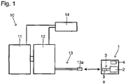
- FIG. 1 conceptually shows a hydrogen filling apparatus 10.
- the hydrogen filling apparatus 10 is provided at a so-called hydrogen station.
- Hydrogen is supplied from the hydrogen filling apparatus 10 to a hydrogen tank 2 that is included in an automobile (fuel cell electric vehicle) 1 equipped with a fuel cell.
- the fuel cell electric vehicle 1 is as known.
- a fuel cell system is provided inside a body of the fuel cell electric vehicle 1.
- the fuel cell system is provided with a fuel cell and the hydrogen tank 2.
- Hydrogen is supplied from the hydrogen tank 2 to the fuel cell.
- the fuel cell generates electricity by oxidizing, with a separately supplied oxidizing gas (air), hydrogen that is supplied from the hydrogen tank 2 and used as a fuel gas.
- a motor that is a driving source of the vehicle is rotated by this generated electricity.
- the hydrogen tank 2 can be efficiently filled with hydrogen even when the fuel cell electric vehicle 1 is such a particularly large-sized vehicle that the hydrogen tank 2 has a capacity more than 30 kg.
- the hydrogen filling apparatus 10 is provided with an accumulator 11 in which hydrogen is sealed, a compressor 12 to compress (pressurize) hydrogen released from the accumulator 11 to piping, a hydrogen supply pipe 13 to supply the pressurized hydrogen from the compressor 12 to the fuel cell electric vehicle 1, and a control unit 14 controlling the supply of hydrogen.
- a control unit 14 controlling the supply of hydrogen.
- known ones may be used as the accumulator 11, the compressor 12 and the hydrogen supply pipe 13 without any particular limitations.
- the hydrogen tank 2 is filled with hydrogen by connecting a nozzle 13a provided at the head of the hydrogen supply pipe 13 to a receptacle (filling port) 3a provided at the head of a hydrogen introducing pipe 3 of the fuel cell electric vehicle 1, compressing hydrogen released from the inside of the accumulator 11 by the compressor 12, and passing the released hydrogen through the hydrogen supply pipe 13 and the hydrogen introducing pipe 3 of the fuel cell electric vehicle 1.
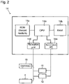
- the control unit 14 controls respective parts of the hydrogen filling apparatus 10. As conceptually shown in Fig. 2 , the control unit 14 is provided with a CPU (Central Processing Unit) 14a that is a processor, a RAM (Random Access Memory) 14b that operates as a work area, a ROM (Read-Only Memory) 14c that operates as a record medium, a reception unit 14d that is an interface for the control unit 14 to receive both wired information and wireless information, and a transmission unit 14e that is an interface for the control unit 14 to transmit both wired information and wireless information to the outside.
- a CPU Central Processing Unit
- RAM Random Access Memory
- ROM Read-Only Memory
- control unit 14 is configured to be connected to other devices via the reception unit 14d and the transmission unit 14e so as to be able to transmit and receive signals.
- a control program for controlling respective parts of the hydrogen filling apparatus 10 is stored in the control unit 14.
- the CPU 14a, the RAM 14b and the ROM 14c as hardware resources cooperate with the control programs as computer programs.
- the CPU 14a executes, in the RAM 14b that operates as a work area, computer programs recorded in the ROM 14c, thereby enabling various functions.
- Information acquired or created by the CPU 14a is stored in the RAM 14b.
- control unit 14 acquires, from the control unit 4 of the fuel cell electric vehicle 1 via the reception unit 14d, the type of filling port (receptacle) 3a of the fuel cell electric vehicle 1, and the capacity of the hydrogen tank 2.
- the number of the filling port(s) (receptacle(s)) 3a may be acquired if necessary.
- the control unit 14 executes computer programs recorded in the ROM 14c, for example, using a database recorded in the ROM 14c, determines the pressure rise rate in hydrogen filling, and records the determined rate in the RAM 14b.
- the control unit 14 controls the compressor 12 via the transmission unit 14e so that hydrogen filling can be performed at the determined pressure rise rate, and then the hydrogen tank 2 is filled with hydrogen. A specific method of determining the pressure rise rate will be described later.
- control unit 14 executes computer programs recorded based on information (signals) from provided sensors and devices, and controls respective parts of the hydrogen filling apparatus 10.
- the sensors and devices include a hydrogen flow meter, a temperature sensor, a pressure sensor, and valves adapted to control the flow of hydrogen.
- the fuel cell electric vehicle 1 is filled with hydrogen as described above.
- the pressure rise rate for hydrogen filling is calculated and hydrogen filling is controlled based on its result.
- the method of determining the pressure rise rate will be described.
- Hydrogen filling can be controlled by creating a computer program having a step corresponding to respective steps of this method, storing the created programs in the ROM 14c that operates as a record medium of the control unit 14, and executing the programs.
- a hydrogen filling method according to one example will be described.
- a computer program created based on this method functions as one component of the hydrogen filling apparatus 10 by recording this program in the ROM 14c of the control unit 14 as described above.
- Fig. 3 shows the flow of a hydrogen filling method S10 according to one embodiment.
- the hydrogen filling method S10 has step S11 of acquiring information, step S12 of determining the pressure rise rate, and step S13 of hydrogen filling.
- step S11 of acquiring information e.g., acquiring information
- step S12 of determining the pressure rise rate e.g., determining the pressure rise rate
- step S11 of acquiring information the type of filling port (receptacle) 3a for hydrogen in the fuel cell electric vehicle 1, and the capacity of the hydrogen tank 2 are acquired from the fuel cell electric vehicle 1, which is to be filled with hydrogen from now on.
- the number of the filling port(s) 3a may be acquired if necessary.
- Information may be either automatically or manually acquired, or may be information recorded in the control unit 14 as a database in advance.
- Information may be automatically acquired by, for example, receiving, with the reception unit 14d provided in the control unit 14 of the hydrogen filling apparatus 10, information on the type of filling port (receptacle) 3a, the number of the filling port(s) 3a, and the capacity of the hydrogen tank 2 which is wirelessly transmitted from the control unit 4 installed in the fuel cell electric vehicle 1.
- Information may be manually acquired by, for example, receiving, with the reception unit 14d provided in the control unit 14 of the hydrogen filling apparatus 10, information on the type of filling port (receptacle) 3, the number of the filling port(s) 3a, and the capacity of the hydrogen tank 2 via a human input operation with an input means 15 such as a keyboard and a touch panel.
- step S12 of determining the pressure rise rate the pressure rise rate in hydrogen filling is determined based on the information acquired in step S11 of acquiring information.
- K is a coefficient, and is determined by the type of filling port 3a (and further the number of the filling port(s) 3a if necessary), and is obtained in advance by experiment or the like.
- the temperature in the hydrogen tank and the outside air temperature may be considered when the coefficient K is determined.
- the coefficient K may be obtained both in view of such temperature, and based on an actual measurement by experiment or any existing map (e.g., SAE J2601 (North American Standard) or JPEC-S 0003 (Japanese Standards)).
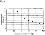
- Fig. 4 is a graph showing the relation between the capacity (kg) of the hydrogen tank and the pressure rise rate (MPa/min) according to one example.
- the pressure rise rate is obtained from the capacity of the hydrogen tank 2 by applying a relational expression in inverse proportion which is obtained in advance according to the type of filling port 3a (and further the number of the filling port(s) 3a if necessary) like this.
- the pressure rise rate can be obtained by calculation as described above each time.
- the pressure rise rate may be obtained by making classification by predetermined conditions or ranges, obtaining the pressure rise rate according to the classification in advance (in the same way as described above), recording the obtained pressure rise rates in the ROM 14c or the like in the form of a list (map), and calling the map of a classification corresponding to a condition based on the information acquired in step S11 of acquiring information.
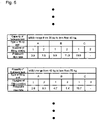
- classification is made according to the hydrogen tank capacity into predetermined ranges (e.g., the range from 10 kg to less than 20 kg, the range from 20 kg to less than 30 kg, the range from 30 kg to less than 40 kg, the range from 40 kg to less than 50 kg, the range from 50 kg to less than 60 kg, ).
- the respective ranges (classifications) are further classified according to the type of filling port, and the number of the filling port(s), the pressure rise rates are calculated, and the results thereof are shown in the form of a list (map).
- the pressure rise rate obtained from a map corresponding to a condition is called based on the information acquired in step S11 of acquiring information.
- These maps may be recorded in, for example, the ROM 14c of the control unit 14.
- step S13 of hydrogen filling hydrogen filling is performed at the pressure rise rate determined in step S12 of determining the pressure rise rate. Hydrogen filling is performed at a proper pressure rise rate as the supply pressure of hydrogen is adjusted by controlling the compressor 12 by the control unit 14 via the transmission unit 14e based on the information on the determined pressure rise rate.
- the hydrogen filling apparatus 10, and the control of the pressure rise rate by the hydrogen filling method S10 described above allow the hydrogen tank 2 to be efficiently filled with hydrogen even when the hydrogen tank 2 has a particularly large capacity.
- the time for hydrogen filling can be shortened, and at the same time the load to the hydrogen tank can be suppressed even when the hydrogen tank has a capacity more than 30 kg (e.g., a hydrogen tank installed in a large-sized vehicle).
- the pressure rise rate is computed by the control unit 14 provided in the hydrogen filling apparatus 10 as described above as an example.
- the present disclosure is not limited to this.
- the pressure rise rate may be calculated by a control unit (engine control unit or ECU, or the like) 4 provided in the fuel cell electric vehicle 1.
- a control unit engine control unit or ECU, or the like
- the nozzle 13a at the head of the hydrogen supply pipe 13 provided in the hydrogen filling apparatus 10, and the filling port (receptacle) 3a provided at the hydrogen introducing pipe 3 disposed in the fuel cell electric vehicle 1 are connected to each other, and then the hydrogen tank 2 is filled with hydrogen.
- the connection of the nozzle 13a and the receptacle 3a that are different types from each other even allows hydrogen filling, but in some cases, may cause efficiency of the filling to decrease, or some fault. For example, such decrease or fault tends to be shown or occur noticeably when the nozzle 13a of a larger allowable maximum hydrogen pressure or maximum hydrogen flow than the receptacle 3a is combined to this receptacle 3a.
- the combination of the nozzle 13a and the receptacle 3a that are different types from each other in such a way that the nozzle 13a and the receptacle 3a cannot to be physically connected to each other.
- "Cannot be physically connected” means that at least one of the nozzle 13a and the receptacle 3a has a structure that prevents both from being connected to each other.
- the receptacle 3a may be provided with a projection to prevent the nozzle 13a from being connected thereto. It is noted that the structure is not limited to this.
- the combination of the nozzle 13a and the receptacle 3a that are at least some different types from each other is configured in such a way that the nozzle 13a and the receptacle 3a can be physically connected to each other, and then hydrogen filling is controlled by the control unit 14. Further specific descriptions are as follows.
- nozzle pressure means the allowable maximum hydrogen pressure of the nozzle
- nozzle flow means the allowable maximum hydrogen flow of the nozzle
- receptacle pressure means the allowable maximum hydrogen pressure of the receptacle
- receptacle flow means the allowable maximum hydrogen flow of the receptacle.
- the number of the types of nozzle 13a and receptacle 3a is not particular limited. Here, as one example, a description in a case where there are the following types of nozzle 13a and receptacle 3a will be given.
- the relation among pressures by magnitude is as follows: pressure A ⁇ pressure B ⁇ pressure C ⁇ pressure D.
- the relation among the flows by volume is as follows: small flow ⁇ moderate flow ⁇ large flow.
- pressure A may be 11 MPa
- pressure B may be 25 MPa
- pressure C may be 35 MPa
- pressure D may be 70 MPa
- small flow may be 60 g/s
- moderate flow may be 90 g/s
- large flow may be 120 g/s.
- Fig. 6 shows the nozzles and the receptacles connectable and non-connectable to each other in this example.
- the combination of the nozzle and the receptacle that can be connected to each other is indicated by the circle or the double circle, and the combination of the nozzle and the receptacle that cannot be connected to each other is indicated by the cross.
- the nozzle and the receptacle are physically connectable when the nozzle having a nozzle pressure equal to or smaller than the receptacle pressure of the receptacle and having a nozzle flow equal to or smaller than the receptacle flow of the receptacle is combined with this receptacle; and physically non-connectable unless satisfying the above condition.
- the nozzle and the receptacle can be connected when the receptacle having a low flow and the nozzle having a moderate or large flow are combined, and when the receptacle having a moderate flow and the nozzle having a large flow are combined under the condition that the nozzle 13a having a nozzle pressure of pressure D and the receptacle 3a having a receptacle pressure of pressure D are combined, as indicated by the double circle in Fig. 6 .
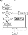
- Fig. 7 shows the flow of a method S20 of this control.
- the fuel cell electric vehicle 1 is filled with hydrogen under the control by the method S20 as described below.
- hydrogen filling can be also controlled by creating a computer program having a step corresponding to respective steps of this method, storing the created programs in the ROM 14c that operates as a record medium of the control unit 14, and executing the programs.
- a hydrogen filling method S20 according to one example will be described.
- a computer program created based on this method functions as one component of the hydrogen filling apparatus 10 by recording this program in the ROM 14c of the control unit 14 as described above.
- the hydrogen filling method S20 has step S21 of executing acquisition of information, step S22 of determining whether or not the type has been acquired, step S23 of determining filling at the small flow or less, step S24 of comparing the nozzle flow and the receptacle flow, step S25 of determining filling at the receptacle flow or less, step S26 of determining filling at the nozzle flow or less, and step S27 of hydrogen filling.
- step S21 of executing acquisition of information at least the type of receptacle 3a in the fuel cell electric vehicle 1 is tried to be acquired from the fuel cell electric vehicle 1 to be filled with hydrogen.
- the acquisition of information may be executed by, for example, receiving, with the reception unit 14d provided in the control unit 14 of the hydrogen filling apparatus 10, information on the type of receptacle 3a which is wirelessly transmitted from the control unit 4 installed in the fuel cell electric vehicle 1.
- step S22 of determining whether or not the type has been acquired it is determined whether the information on the type of receptacle 3a has been acquired in step S21 of executing acquisition of information.
- the process moves to step S23 of determining filling at the small flow or less.
- the reason why the type of receptacle 3a cannot be acquired is not particularly limited. The reason may be that the control unit 4 is originally not installed in the fuel cell electric vehicle 1 and thus any information cannot be outputted, or that the information cannot be outputted due to any fault or the like even when the control unit 4 is installed.
- step S22 of determining whether or not the type has been acquired, and No is selected the process moves to step S23 of determining filling at the small flow or less, and it is determined that hydrogen filling is performed at the small flow or less. Thereafter the process moves to step S27 of hydrogen filling, and hydrogen filling is performed based on this determination.
- step S22 of determining whether or not the type has been acquired the process moves to step S24 of comparing the nozzle flow and the receptacle flow, and the nozzle flow and the receptacle flow are compared to each other.
- step S22 of determining whether or not the type has been acquired Yes is selected, and the process moves to step S25 of determining filling at the receptacle flow or smaller.
- step S22 of determining whether or not the type has been acquired No is selected, and the process moves to step S26 of determining filling at the nozzle flow or less.
- step S24 of comparing the nozzle flow and the receptacle flow Yes is selected, the process moves to step S25 of determining filling at the receptacle flow or less, and it is determined that hydrogen filling is performed at the receptacle flow or less. Thereafter the process moves to step S27 of hydrogen filling, and hydrogen filling is performed based on this determination.
- step S24 of comparing the nozzle flow and the receptacle flow, No is selected, the process moves to step S26 of determining filling at the nozzle flow or less, and it is determined that hydrogen filling is performed at the nozzle flow or less. Thereafter the process moves to step S27 of hydrogen filling, and hydrogen filling is performed based on this determination.
- step S27 of hydrogen filling hydrogen filling is performed at the flow based on the determination in step S23 of determining filling at the small flow or less, step S25 of determining filling at the receptacle flow or less, or step S26 of determining filling at the nozzle flow or less.
- Hydrogen filling is performed at a proper flow by, for example, controlling the compressor 12 by the control unit 14 via the transmission unit 14e based on information on the determined flow, and then adjusting the supply pressure of hydrogen.
Landscapes
- Engineering & Computer Science (AREA)
- Mechanical Engineering (AREA)
- General Engineering & Computer Science (AREA)
- Filling Or Discharging Of Gas Storage Vessels (AREA)
- Fuel Cell (AREA)
Abstract
Description
- The present disclosure relates to hydrogen filling.
-
Patent Literature 1 discloses a hydrogen filling device adapted to transmit information on a vehicle to be filled with hydrogen (for example, the capacity of a hydrogen tank) to a control unit through infrared communication, the control unit specifying hydrogen filling control (protocol). It is shown there that in hydrogen filling, the pressure rise rate is determined by the capacity of the tank, the initial pressure, and the outside air temperature. - Patent Literature 1:
JP 2019-2515 A - When a large-sized vehicle is a fuel cell electric vehicle, the capacity of hydrogen gas filling within 30 kg, which is provided by the existing standard, cannot keep driving distance of the large-sized vehicle sufficient. In this case, the filling amount at one time increases because the capacity of hydrogen gas increases. Thus, the filling time tends to be longer, and not only filling at a conventional filling speed but also filling at a faster speed (so-called large flow) is necessary for short-term filling.
- As described above, conventional hydrogen filling is controlled on the assumption that a hydrogen tank has a capacity up to 30 kg. When conventional control is performed with a hydrogen tank having a capacity more than 30 kg (e.g., hydrogen tank installed in a large-sized vehicle), the filling time may be longer, or the supply of hydrogen may be stopped at the time point when the tank has been filled with 30 kg hydrogen.
- In view of the above problems, an object of the present disclosure is to enable a hydrogen tank to be efficiently filled with hydrogen even when the hydrogen tank has a large capacity.
- As a result of their intensive research, the inventors of the present application found that the factor influencing filling of a hydrogen tank of a particularly large capacity with hydrogen is not only the capacity of the hydrogen tank but also the type of filling port, and a proper pressure rise rate based on these factor is in inverse proportion relation to the capacity of the hydrogen tank.
- Here, " pressure rise rate" means rise pressure per unit time in a hydrogen tank, and is represented by, for example, "MPa/min". Hydrogen filling at a proper pressure rise rate allows the hydrogen tank to be efficiently and properly filled with hydrogen.
- A nozzle at the head of a hydrogen supply pipe provided in a hydrogen filling apparatus, and a filling port (receptacle) provided at a hydrogen introducing pipe disposed in a fuel cell electric vehicle are connected to each other, and then a hydrogen tank is filled with hydrogen. Usually, there are plural types of nozzle and receptacle according to the allowable maximum hydrogen pressures and maximum hydrogen flows. The connection of a nozzle and a receptacle that are different types from each other may cause some fault in hydrogen filling. For example, such fault tends to be noticeable when a nozzle of a larger allowable maximum hydrogen pressure or maximum hydrogen flow than a receptacle is combined to this receptacle.
- For this, one may use a structure of a nozzle and a receptacle which prevents the nozzle and the receptacle from being physically connected to each other, and prohibit hydrogen filling when the nozzle and the receptacle of different types from each other are combined. However, the complete prohibition when such a nozzle and a receptacle are combined causes a case where filling is prohibited to be more often, and prevents efficient hydrogen filling in terms of wide use. Therefore, for efficient filling, the inventors of the present application arrived at an idea that it is a significant benefit for the improvement of efficiency that filling can be performed even when a nozzle and a receptacle that are different types from each other are connected.
- Based on the above findings, the present application discloses, as one means for solving the problems, a method of filling a hydrogen tank with hydrogen, the method comprising: prohibiting hydrogen filling at a nozzle flow when the nozzle flow of a nozzle is larger than a receptacle flow of a receptacle or when the receptacle flow is unknown under a condition that the nozzle and the receptacle can be connected to each other.
- The method may further comprise performing the hydrogen filling at the receptacle flow or less.
- In the method, the nozzle and the receptacle can be connected to each other when a nozzle pressure of the nozzle is equal to or lower than a receptacle pressure of the receptacle.
- The method may further comprise: determining a pressure rise rate in the hydrogen filling based on inverse proportion relation to a capacity of the hydrogen tank from a type of receptacle and the capacity of the hydrogen tank.
- In the method, a map where a value of the pressure rise rate is determined based on the inverse proportion relation may be created, and the pressure rise rate may be determined by the map.
- As another aspect of the present disclosure, disclosed is a hydrogen filling apparatus adapted to fill a hydrogen tank with hydrogen, the apparatus comprising: an accumulator; a compressor; a hydrogen supply pipe, a nozzle disposed at a head of the hydrogen supply pipe; and a control unit controlling the compressor, wherein the control unit performs a calculation of prohibition of hydrogen filling at a nozzle flow when the nozzle flow of the nozzle is larger than a receptacle flow of a receptacle or when the receptacle flow is unknown under a condition that the nozzle and the receptacle can be connected to each other.
- In the hydrogen filling apparatus, the control unit may determine that the hydrogen filling is performed at the receptacle flow or less.
- In the hydrogen filling apparatus, the nozzle and the receptacle can be connected to each other when a nozzle pressure of the nozzle is equal to or lower than a receptacle pressure of the receptacle.
- In the hydrogen filling apparatus, the control unit may perform a calculation of determining a pressure rise rate based on inverse proportion relation to a capacity of the hydrogen tank from a type of receptacle and the capacity of the hydrogen tank.
- In the hydrogen filling apparatus, a map where a value of the pressure rise rate is based on the inverse proportion relation may be recorded in the control unit, and the pressure rise rate may be determined by the map.
- As another aspect of the present disclosure, disclosed is a computer program to execute control of filling a hydrogen tank with hydrogen, the computer program comprising: prohibiting hydrogen filling at a nozzle flow when the nozzle flow of a nozzle is larger than a receptacle flow of a receptacle or when the receptacle flow is unknown.
- The computer program may further comprise determining that the hydrogen filling is performed at the receptacle flow or less.
- The computer program may further comprise: obtaining a pressure rise rate based on inverse proportion relation to a capacity of the hydrogen tank from a type of receptacle and the capacity of the hydrogen tank.
- A record medium storing the above computer program is also disclosed. Advantageous Effects
- According to the present disclosure, a hydrogen tank can be efficiently filled with hydrogen even when the hydrogen tank has a large capacity.
-
-
Fig. 1 schematically shows ahydrogen filling apparatus 10; -
Fig. 2 schematically shows acontrol unit 14; -
Fig. 3 shows a flow of a hydrogen filling method S10; -
Fig. 4 shows an example of the relation between the capacity of a hydrogen tank and the pressure rise rate; -
Fig. 5 explanatorily shows one example of maps; -
Fig. 6 shows one example of nozzles and receptacles connectable and non-connectable to each other; and -
Fig. 7 shows a flow of a hydrogen filling method S20. - A hydrogen filling apparatus according to one example will be described with reference to drawings.
Fig. 1 conceptually shows ahydrogen filling apparatus 10. Thehydrogen filling apparatus 10 is provided at a so-called hydrogen station. Hydrogen is supplied from thehydrogen filling apparatus 10 to ahydrogen tank 2 that is included in an automobile (fuel cell electric vehicle) 1 equipped with a fuel cell. - Here, the fuel cell
electric vehicle 1 is as known. A fuel cell system is provided inside a body of the fuel cellelectric vehicle 1. The fuel cell system is provided with a fuel cell and thehydrogen tank 2. Hydrogen is supplied from thehydrogen tank 2 to the fuel cell. The fuel cell generates electricity by oxidizing, with a separately supplied oxidizing gas (air), hydrogen that is supplied from thehydrogen tank 2 and used as a fuel gas. A motor that is a driving source of the vehicle is rotated by this generated electricity. According to the present disclosure, as described above, thehydrogen tank 2 can be efficiently filled with hydrogen even when the fuel cellelectric vehicle 1 is such a particularly large-sized vehicle that thehydrogen tank 2 has a capacity more than 30 kg. - The
hydrogen filling apparatus 10 is provided with anaccumulator 11 in which hydrogen is sealed, acompressor 12 to compress (pressurize) hydrogen released from theaccumulator 11 to piping, ahydrogen supply pipe 13 to supply the pressurized hydrogen from thecompressor 12 to the fuel cellelectric vehicle 1, and acontrol unit 14 controlling the supply of hydrogen. Here, known ones may be used as theaccumulator 11, thecompressor 12 and thehydrogen supply pipe 13 without any particular limitations. Thehydrogen tank 2 is filled with hydrogen by connecting anozzle 13a provided at the head of thehydrogen supply pipe 13 to a receptacle (filling port) 3a provided at the head of ahydrogen introducing pipe 3 of the fuel cellelectric vehicle 1, compressing hydrogen released from the inside of theaccumulator 11 by thecompressor 12, and passing the released hydrogen through thehydrogen supply pipe 13 and thehydrogen introducing pipe 3 of the fuel cellelectric vehicle 1. - The
control unit 14 controls respective parts of thehydrogen filling apparatus 10. As conceptually shown inFig. 2 , thecontrol unit 14 is provided with a CPU (Central Processing Unit) 14a that is a processor, a RAM (Random Access Memory) 14b that operates as a work area, a ROM (Read-Only Memory) 14c that operates as a record medium, areception unit 14d that is an interface for thecontrol unit 14 to receive both wired information and wireless information, and atransmission unit 14e that is an interface for thecontrol unit 14 to transmit both wired information and wireless information to the outside. - Therefore, the
control unit 14 is configured to be connected to other devices via thereception unit 14d and thetransmission unit 14e so as to be able to transmit and receive signals. - A control program for controlling respective parts of the
hydrogen filling apparatus 10 is stored in thecontrol unit 14. In thecontrol unit 14, theCPU 14a, theRAM 14b and theROM 14c as hardware resources cooperate with the control programs as computer programs. Specifically, theCPU 14a executes, in theRAM 14b that operates as a work area, computer programs recorded in theROM 14c, thereby enabling various functions. Information acquired or created by theCPU 14a is stored in theRAM 14b. - In this embodiment, the
control unit 14 acquires, from thecontrol unit 4 of the fuel cellelectric vehicle 1 via thereception unit 14d, the type of filling port (receptacle) 3a of the fuel cellelectric vehicle 1, and the capacity of thehydrogen tank 2. The number of the filling port(s) (receptacle(s)) 3a may be acquired if necessary. - In this embodiment, based on the acquired information, the
control unit 14 executes computer programs recorded in theROM 14c, for example, using a database recorded in theROM 14c, determines the pressure rise rate in hydrogen filling, and records the determined rate in theRAM 14b. Thecontrol unit 14 controls thecompressor 12 via thetransmission unit 14e so that hydrogen filling can be performed at the determined pressure rise rate, and then thehydrogen tank 2 is filled with hydrogen. A specific method of determining the pressure rise rate will be described later. - In addition, the
control unit 14 executes computer programs recorded based on information (signals) from provided sensors and devices, and controls respective parts of thehydrogen filling apparatus 10. Examples of the sensors and devices include a hydrogen flow meter, a temperature sensor, a pressure sensor, and valves adapted to control the flow of hydrogen. - Next, hydrogen filling will be described.
- The fuel cell
electric vehicle 1 is filled with hydrogen as described above. In the present disclosure, when hydrogen filling is performed, the pressure rise rate for hydrogen filling is calculated and hydrogen filling is controlled based on its result. Here, the method of determining the pressure rise rate will be described. Hydrogen filling can be controlled by creating a computer program having a step corresponding to respective steps of this method, storing the created programs in theROM 14c that operates as a record medium of thecontrol unit 14, and executing the programs. Hereinafter a hydrogen filling method according to one example will be described. A computer program created based on this method functions as one component of thehydrogen filling apparatus 10 by recording this program in theROM 14c of thecontrol unit 14 as described above. -
Fig. 3 shows the flow of a hydrogen filling method S10 according to one embodiment. As can be seen fromFig. 3 , the hydrogen filling method S10 has step S11 of acquiring information, step S12 of determining the pressure rise rate, and step S13 of hydrogen filling. Hereinafter respective steps will be described. - In step S11 of acquiring information, the type of filling port (receptacle) 3a for hydrogen in the fuel cell
electric vehicle 1, and the capacity of thehydrogen tank 2 are acquired from the fuel cellelectric vehicle 1, which is to be filled with hydrogen from now on. The number of the filling port(s) 3a may be acquired if necessary. - Information may be either automatically or manually acquired, or may be information recorded in the
control unit 14 as a database in advance. - Information may be automatically acquired by, for example, receiving, with the
reception unit 14d provided in thecontrol unit 14 of thehydrogen filling apparatus 10, information on the type of filling port (receptacle) 3a, the number of the filling port(s) 3a, and the capacity of thehydrogen tank 2 which is wirelessly transmitted from thecontrol unit 4 installed in the fuel cellelectric vehicle 1. - Information may be manually acquired by, for example, receiving, with the
reception unit 14d provided in thecontrol unit 14 of thehydrogen filling apparatus 10, information on the type of filling port (receptacle) 3, the number of the filling port(s) 3a, and the capacity of thehydrogen tank 2 via a human input operation with an input means 15 such as a keyboard and a touch panel. - In step S12 of determining the pressure rise rate, the pressure rise rate in hydrogen filling is determined based on the information acquired in step S11 of acquiring information. In the present disclosure, the pressure rise rate is basically determined by inverse proportion relation to the capacity of the
hydrogen tank 2. That is, the pressure rise rate is computed using
hydrogen tank 2 is M (kg). - Here, K is a coefficient, and is determined by the type of filling port 3a (and further the number of the filling port(s) 3a if necessary), and is obtained in advance by experiment or the like. The temperature in the hydrogen tank and the outside air temperature may be considered when the coefficient K is determined. The coefficient K may be obtained both in view of such temperature, and based on an actual measurement by experiment or any existing map (e.g., SAE J2601 (North American Standard) or JPEC-S 0003 (Japanese Standards)).
-
Fig. 4 is a graph showing the relation between the capacity (kg) of the hydrogen tank and the pressure rise rate (MPa/min) according to one example. The pressure rise rate is obtained from the capacity of thehydrogen tank 2 by applying a relational expression in inverse proportion which is obtained in advance according to the type of filling port 3a (and further the number of the filling port(s) 3a if necessary) like this. - The pressure rise rate can be obtained by calculation as described above each time. The pressure rise rate may be obtained by making classification by predetermined conditions or ranges, obtaining the pressure rise rate according to the classification in advance (in the same way as described above), recording the obtained pressure rise rates in the
ROM 14c or the like in the form of a list (map), and calling the map of a classification corresponding to a condition based on the information acquired in step S11 of acquiring information. - For example, as shown in
Fig. 5 , classification is made according to the hydrogen tank capacity into predetermined ranges (e.g., the range from 10 kg to less than 20 kg, the range from 20 kg to less than 30 kg, the range from 30 kg to less than 40 kg, the range from 40 kg to less than 50 kg, the range from 50 kg to less than 60 kg, ...). The respective ranges (classifications) are further classified according to the type of filling port, and the number of the filling port(s), the pressure rise rates are calculated, and the results thereof are shown in the form of a list (map). The pressure rise rate obtained from a map corresponding to a condition is called based on the information acquired in step S11 of acquiring information. These maps may be recorded in, for example, theROM 14c of thecontrol unit 14. - Similarly, one may make classification according to the type of filling port (and further, the number of the filling port(s) if necessary), further classify the respective types (or the respective numbers) according to the hydrogen tank capacity, calculate the pressure rise rates and show the results thereof in the form of a list (map), and call the pressure rise rate obtained from a map corresponding to a condition based on the information acquired in step S11 of acquiring information.
- In step S13 of hydrogen filling, hydrogen filling is performed at the pressure rise rate determined in step S12 of determining the pressure rise rate. Hydrogen filling is performed at a proper pressure rise rate as the supply pressure of hydrogen is adjusted by controlling the
compressor 12 by thecontrol unit 14 via thetransmission unit 14e based on the information on the determined pressure rise rate. - The
hydrogen filling apparatus 10, and the control of the pressure rise rate by the hydrogen filling method S10 described above allow thehydrogen tank 2 to be efficiently filled with hydrogen even when thehydrogen tank 2 has a particularly large capacity. In other words, for example, the time for hydrogen filling can be shortened, and at the same time the load to the hydrogen tank can be suppressed even when the hydrogen tank has a capacity more than 30 kg (e.g., a hydrogen tank installed in a large-sized vehicle). - The pressure rise rate is computed by the
control unit 14 provided in thehydrogen filling apparatus 10 as described above as an example. The present disclosure is not limited to this. In addition to this, the pressure rise rate may be calculated by a control unit (engine control unit or ECU, or the like) 4 provided in the fuel cellelectric vehicle 1. At this time, for example, for improvement of safety, one may compare the pressure rise rate obtained in the hydrogen filling apparatus and the pressure rise rate obtained in the fuel cell electric vehicle, and allow filling if the difference between the values thereof is within a certain range and prohibit filling if not, or perform filling at a lower pressure rise rate in both the pressure rise rates. - As described above, the
nozzle 13a at the head of thehydrogen supply pipe 13 provided in thehydrogen filling apparatus 10, and the filling port (receptacle) 3a provided at thehydrogen introducing pipe 3 disposed in the fuel cellelectric vehicle 1 are connected to each other, and then thehydrogen tank 2 is filled with hydrogen. Usually, there are plural types ofnozzle 13a and receptacle 3a according to the allowable maximum hydrogen pressures and maximum hydrogen flows. The connection of thenozzle 13a and the receptacle 3a that are different types from each other even allows hydrogen filling, but in some cases, may cause efficiency of the filling to decrease, or some fault. For example, such decrease or fault tends to be shown or occur noticeably when thenozzle 13a of a larger allowable maximum hydrogen pressure or maximum hydrogen flow than the receptacle 3a is combined to this receptacle 3a. - For this, for hydrogen filling, one may configure the combination of the
nozzle 13a and the receptacle 3a that are different types from each other in such a way that thenozzle 13a and the receptacle 3a cannot to be physically connected to each other. "Cannot be physically connected" means that at least one of thenozzle 13a and the receptacle 3a has a structure that prevents both from being connected to each other. For example, the receptacle 3a may be provided with a projection to prevent thenozzle 13a from being connected thereto. It is noted that the structure is not limited to this. - On the contrary, however, when the
nozzle 13a and the receptacle 3a cannot be connected to each other at all when thenozzle 13a and the receptacle 3a that are different types from each other are combined, a case where filling is prohibited becomes more often, and efficient hydrogen filling in terms of wide use is prevented. - Therefore, in the present disclosure, the combination of the
nozzle 13a and the receptacle 3a that are at least some different types from each other is configured in such a way that thenozzle 13a and the receptacle 3a can be physically connected to each other, and then hydrogen filling is controlled by thecontrol unit 14. Further specific descriptions are as follows. - As described above, there are plural types of
nozzle 13a and receptacle 3a according to the allowable maximum hydrogen pressures and maximum hydrogen flows. Here, as expressions, "nozzle pressure" means the allowable maximum hydrogen pressure of the nozzle, and "nozzle flow" means the allowable maximum hydrogen flow of the nozzle. Likewise, "receptacle pressure" means the allowable maximum hydrogen pressure of the receptacle, and "receptacle flow" means the allowable maximum hydrogen flow of the receptacle. - The number of the types of
nozzle 13a and receptacle 3a is not particular limited. Here, as one example, a description in a case where there are the following types ofnozzle 13a and receptacle 3a will be given. The relation among pressures by magnitude is as follows: pressure A < pressure B < pressure C < pressure D. The relation among the flows by volume is as follows: small flow < moderate flow < large flow. - Nozzle 1 (N1): nozzle pressure is pressure A, nozzle flow is small flow
- Nozzle 2 (N2): nozzle pressure is pressure B, nozzle flow is small flow
- Nozzle 3 (N3): nozzle pressure is pressure C, nozzle flow is small flow
- Nozzle 4 (N4): nozzle pressure is pressure C, nozzle flow is large flow
- Nozzle 5 (N5): nozzle pressure is pressure D, nozzle flow is small flow
- Nozzle 6 (N6): nozzle pressure is pressure D, nozzle flow is moderate flow
- Nozzle 7 (N7): nozzle pressure is pressure D, nozzle flow is large flow
- Receptacle 1 (R1): receptacle pressure is pressure A, receptacle flow is small flow
- Receptacle 2 (R2): receptacle pressure is pressure B, receptacle flow is small flow
- Receptacle 3 (R3): receptacle pressure is pressure C, receptacle flow is small flow
- Receptacle 4 (R4): receptacle pressure is pressure C, receptacle flow is large flow
- Receptacle 5 (R5): receptacle pressure is pressure D, receptacle flow is small flow
- Receptacle 6 (R6): receptacle pressure is pressure D, receptacle flow is moderate flow
- Receptacle 7 (R7): receptacle pressure is pressure D, receptacle flow is large flow
- Here, specific values of the nozzle pressure, the receptacle pressure, the nozzle flow, and the receptacle flow are not particularly limited. For example, pressure A may be 11 MPa, pressure B may be 25 MPa, pressure C may be 35 MPa, pressure D may be 70 MPa, small flow may be 60 g/s, moderate flow may be 90 g/s and large flow may be 120 g/s.
- For enabling hydrogen filling, it is necessary that the
nozzle 13a and the receptacle 3a can be physically connected.Fig. 6 shows the nozzles and the receptacles connectable and non-connectable to each other in this example. InFig. 6 , the combination of the nozzle and the receptacle that can be connected to each other is indicated by the circle or the double circle, and the combination of the nozzle and the receptacle that cannot be connected to each other is indicated by the cross. - In this example, basically, the nozzle and the receptacle are physically connectable when the nozzle having a nozzle pressure equal to or smaller than the receptacle pressure of the receptacle and having a nozzle flow equal to or smaller than the receptacle flow of the receptacle is combined with this receptacle; and physically non-connectable unless satisfying the above condition.
- In this example, as an exception, the nozzle and the receptacle can be connected when the receptacle having a low flow and the nozzle having a moderate or large flow are combined, and when the receptacle having a moderate flow and the nozzle having a large flow are combined under the condition that the
nozzle 13a having a nozzle pressure of pressure D and the receptacle 3a having a receptacle pressure of pressure D are combined, as indicated by the double circle inFig. 6 . To ease the conditions for enabling the nozzle and the receptacle to be connected to each other when the nozzle having a higher nozzle pressure and the receptacle having a higher receptacle pressure are combined as described above allows, for example, a case where a hydrogen tank particularly having a capacity more than 30 kg (e.g., a hydrogen tank installed in a large-sized vehicle) is filled with hydrogen to be more often to result in wider use, and thus allows the efficiency for filling to be improved. - As described above, when the
nozzle 13a and the receptacle 3a that can be connected to each other are combined, their connection allows hydrogen filling. In contrast, when the combination of the nozzle and the receptacle is an exception as shown by the double circle inFig. 6 , or when thecontrol unit 14 of thehydrogen filling apparatus 10 cannot recognize the type of receptacle 3a provided in the fuel cellelectric vehicle 1, an unconditional flow of hydrogen to the receptacle 3a having a receptacle flow smaller than the nozzle flow of thenozzle 13a based on the nozzle flow makes the occurrence of faults more likely. - Therefore, in this embodiment, in hydrogen filling, the following control is executed, using the
control unit 14, on thenozzle 13a and the receptacle 3a in combination which have been physically connected.Fig. 7 shows the flow of a method S20 of this control. - The fuel cell
electric vehicle 1 is filled with hydrogen under the control by the method S20 as described below. In this method, hydrogen filling can be also controlled by creating a computer program having a step corresponding to respective steps of this method, storing the created programs in theROM 14c that operates as a record medium of thecontrol unit 14, and executing the programs. Hereinafter a hydrogen filling method S20 according to one example will be described. A computer program created based on this method functions as one component of thehydrogen filling apparatus 10 by recording this program in theROM 14c of thecontrol unit 14 as described above. - As can be seen from
Fig. 7 , the hydrogen filling method S20 has step S21 of executing acquisition of information, step S22 of determining whether or not the type has been acquired, step S23 of determining filling at the small flow or less, step S24 of comparing the nozzle flow and the receptacle flow, step S25 of determining filling at the receptacle flow or less, step S26 of determining filling at the nozzle flow or less, and step S27 of hydrogen filling. Hereinafter the respective steps will be described. - In step S21 of executing acquisition of information, at least the type of receptacle 3a in the fuel cell
electric vehicle 1 is tried to be acquired from the fuel cellelectric vehicle 1 to be filled with hydrogen. - The acquisition of information may be executed by, for example, receiving, with the
reception unit 14d provided in thecontrol unit 14 of thehydrogen filling apparatus 10, information on the type of receptacle 3a which is wirelessly transmitted from thecontrol unit 4 installed in the fuel cellelectric vehicle 1. - In step S22 of determining whether or not the type has been acquired, it is determined whether the information on the type of receptacle 3a has been acquired in step S21 of executing acquisition of information.
- When it is determined that the type of receptacle 3a has been acquired, Yes is selected, and the process moves to step S24 of comparing the nozzle flow and the receptacle flow.
- When it is determined that the type of receptacle 3a cannot be acquired, No is selected, and the process moves to step S23 of determining filling at the small flow or less. Here, the reason why the type of receptacle 3a cannot be acquired is not particularly limited. The reason may be that the
control unit 4 is originally not installed in the fuel cellelectric vehicle 1 and thus any information cannot be outputted, or that the information cannot be outputted due to any fault or the like even when thecontrol unit 4 is installed. - When it is determined that the type of receptacle 3a cannot be acquired in step S22 of determining whether or not the type has been acquired, and No is selected, the process moves to step S23 of determining filling at the small flow or less, and it is determined that hydrogen filling is performed at the small flow or less. Thereafter the process moves to step S27 of hydrogen filling, and hydrogen filling is performed based on this determination.
- According to this step, hydrogen filling at the nozzle flow is prohibited when the type of receptacle 3a cannot be acquired, and the
nozzle 13a and the receptacle 3a have been connected to each other but their relation by flow is unknown. Then, hydrogen filling is performed at the small flow, thereby can prevent faults from occurring. - When it is determined that the type of receptacle 3a has been acquired in step S22 of determining whether or not the type has been acquired, and Yes is selected, the process moves to step S24 of comparing the nozzle flow and the receptacle flow, and the nozzle flow and the receptacle flow are compared to each other.
- In this step, when it is determined that the nozzle flow is larger than the receptacle flow by the information obtained in step S22 of determining whether or not the type has been acquired, Yes is selected, and the process moves to step S25 of determining filling at the receptacle flow or smaller.
- When it is determined that the nozzle flow is equal to or smaller than the receptacle flow by the information acquired in step S22 of determining whether or not the type has been acquired, No is selected, and the process moves to step S26 of determining filling at the nozzle flow or less.
- When it is determined that the nozzle flow is larger than the receptacle flow in step S24 of comparing the nozzle flow and the receptacle flow, Yes is selected, the process moves to step S25 of determining filling at the receptacle flow or less, and it is determined that hydrogen filling is performed at the receptacle flow or less. Thereafter the process moves to step S27 of hydrogen filling, and hydrogen filling is performed based on this determination.
- According to this step, hydrogen filling at the nozzle flow is prohibited when the nozzle flow is larger than the receptacle flow. Hydrogen filling is performed at a flow according to and not exceeding the receptacle flow. Then, faults can be prevented from occurring even when the nozzle and the receptacle that is a type of a receptacle flow smaller than the nozzle flow are connected.
- When it is determined that the nozzle flow is equal to or smaller than the receptacle flow in step S24 of comparing the nozzle flow and the receptacle flow, No is selected, the process moves to step S26 of determining filling at the nozzle flow or less, and it is determined that hydrogen filling is performed at the nozzle flow or less. Thereafter the process moves to step S27 of hydrogen filling, and hydrogen filling is performed based on this determination.
- According to this step, hydrogen filling is performed according to the nozzle flow since the nozzle flow is equal to or smaller than the receptacle flow. Thus, faults can be prevented from occurring.
- In step S27 of hydrogen filling, hydrogen filling is performed at the flow based on the determination in step S23 of determining filling at the small flow or less, step S25 of determining filling at the receptacle flow or less, or step S26 of determining filling at the nozzle flow or less. Hydrogen filling is performed at a proper flow by, for example, controlling the
compressor 12 by thecontrol unit 14 via thetransmission unit 14e based on information on the determined flow, and then adjusting the supply pressure of hydrogen. - One may determine the pressure rise rate in hydrogen filling by the above described method S10, and progress the hydrogen filling at the determined pressure rise rate. This allows further efficient hydrogen filling. It is noted that the pressure rise rate is not limited to this.
- According to the above described hydrogen filling control with the
hydrogen filling apparatus 10, by the hydrogen filling method S20, etc., at least part of the combinations of thenozzle 13a and the receptacle 3a is allowed when thenozzle 13a and the receptacle 3a are different types from each other, and then hydrogen filling can be performed. Thus, a case of hydrogen filling can become more often, and efficient filling in terms of wide use can be performed. -
- 10 hydrogen filling apparatus
- 11 accumulator
- 12 compressor
- 13 hydrogen supply pipe
- 13a nozzle
- 14 control unit
- S10 hydrogen filling method
- S20 hydrogen filling method
Claims (14)
- A method of filling a hydrogen tank with hydrogen, the method comprising:
prohibiting hydrogen filling at a nozzle flow when the nozzle flow of a nozzle is larger than a receptacle flow of a receptacle or when the receptacle flow is unknown under a condition that the nozzle and the receptacle can be connected to each other. - The method according to claim 1, further comprising performing the hydrogen filling at the receptacle flow or less.
- The method according to claim 1 or 2, wherein
the nozzle and the receptacle can be connected to each other when a nozzle pressure of the nozzle is equal to or lower than a receptacle pressure of the receptacle. - The method according to any one of claims 1 to 3, further comprising:
determining a pressure rise rate in the hydrogen filling based on inverse proportion relation to a capacity of the hydrogen tank from a type of receptacle and the capacity of the hydrogen tank. - The method according to claim 4, wherein
a map where a value of the pressure rise rate is determined based on the inverse proportion relation is created, and the pressure rise rate is determined by the map. - A hydrogen filling apparatus adapted to fill a hydrogen tank with hydrogen, the apparatus comprising:an accumulator;a compressor;a hydrogen supply pipe,a nozzle disposed at a head of the hydrogen supply pipe; anda control unit controlling the compressor, whereinthe control unit performs a calculation of prohibition of hydrogen filling at a nozzle flow when the nozzle flow of the nozzle is larger than a receptacle flow of a receptacle or when the receptacle flow is unknown under a condition that the nozzle and the receptacle can be connected to each other.
- The hydrogen filling apparatus according to claim 6, wherein the control unit determines that the hydrogen filling is performed at the receptacle flow or less.
- The hydrogen filling apparatus according to claim 6 or 7, wherein
the nozzle and the receptacle can be connected to each other when a nozzle pressure of the nozzle is equal to or lower than a receptacle pressure of the receptacle. - The hydrogen filling apparatus according to any one of claims 6 to 8, wherein
the control unit performs a calculation of determining a pressure rise rate based on inverse proportion relation to a capacity of the hydrogen tank from a type of receptacle and the capacity of the hydrogen tank. - The hydrogen filling apparatus according to claim 9, wherein
a map where a value of the pressure rise rate is determined based on the inverse proportion relation is recorded in the control unit, and the pressure rise rate is determined by the map. - A computer program to execute control of filling a hydrogen tank with hydrogen, the computer program comprising:
prohibiting hydrogen filling at a nozzle flow when the nozzle flow of a nozzle is larger than a receptacle flow of a receptacle or when the receptacle flow is unknown. - The computer program according to claim 11, further comprising determining that the hydrogen filling is performed at the receptacle flow or less.
- The computer program according to claim 11 or 12, further comprising:
obtaining a pressure rise rate based on inverse proportion relation to a capacity of the hydrogen tank from a type of receptacle and the capacity of the hydrogen tank. - A record medium storing the computer program according to any one of claims 11 to 13.
Priority Applications (1)
| Application Number | Priority Date | Filing Date | Title |
|---|---|---|---|
| EP24207105.8A EP4471318A3 (en) | 2021-07-19 | 2022-07-05 | Hydrogen filling method, hydrogen filling apparatus, program, and record medium |
Applications Claiming Priority (2)
| Application Number | Priority Date | Filing Date | Title |
|---|---|---|---|
| JP2021118815 | 2021-07-19 | ||
| JP2021180744A JP7464032B2 (en) | 2021-07-19 | 2021-11-05 | Hydrogen filling method, hydrogen filling device, program, and recording medium |
Related Child Applications (2)
| Application Number | Title | Priority Date | Filing Date |
|---|---|---|---|
| EP24207105.8A Division EP4471318A3 (en) | 2021-07-19 | 2022-07-05 | Hydrogen filling method, hydrogen filling apparatus, program, and record medium |
| EP24207105.8A Division-Into EP4471318A3 (en) | 2021-07-19 | 2022-07-05 | Hydrogen filling method, hydrogen filling apparatus, program, and record medium |
Publications (2)
| Publication Number | Publication Date |
|---|---|
| EP4123213A1 true EP4123213A1 (en) | 2023-01-25 |
| EP4123213B1 EP4123213B1 (en) | 2024-12-04 |
Family
ID=82546989
Family Applications (2)
| Application Number | Title | Priority Date | Filing Date |
|---|---|---|---|
| EP24207105.8A Pending EP4471318A3 (en) | 2021-07-19 | 2022-07-05 | Hydrogen filling method, hydrogen filling apparatus, program, and record medium |
| EP22182978.1A Active EP4123213B1 (en) | 2021-07-19 | 2022-07-05 | Hydrogen filling method, hydrogen filling apparatus, program, and record medium |
Family Applications Before (1)
| Application Number | Title | Priority Date | Filing Date |
|---|---|---|---|
| EP24207105.8A Pending EP4471318A3 (en) | 2021-07-19 | 2022-07-05 | Hydrogen filling method, hydrogen filling apparatus, program, and record medium |
Country Status (6)
| Country | Link |
|---|---|
| US (2) | US12313224B2 (en) |
| EP (2) | EP4471318A3 (en) |
| JP (1) | JP2024024692A (en) |
| KR (3) | KR102728995B1 (en) |
| CN (2) | CN121576518A (en) |
| ES (1) | ES3002746T3 (en) |
Citations (5)
| Publication number | Priority date | Publication date | Assignee | Title |
|---|---|---|---|---|
| JP4492063B2 (en) * | 2003-08-22 | 2010-06-30 | 株式会社豊田中央研究所 | Hydrogen supply station and hydrogen filling method thereof |
| JP2019002515A (en) | 2017-06-16 | 2019-01-10 | 株式会社タツノ | Hydrogen charging device |
| EP3550198A1 (en) * | 2018-03-30 | 2019-10-09 | Honda Motor Co., Ltd. | Gas filling method |
| JP6624132B2 (en) * | 2017-03-15 | 2019-12-25 | トヨタ自動車株式会社 | Vehicle and fuel gas filling method |
| EP3779263A1 (en) * | 2018-03-26 | 2021-02-17 | Eneos Corporation | Method for diagnosing fault in pressure gauge of hydrogen charging system, and method for calibrating pressure gauge of hydrogen charging system |
Family Cites Families (27)
| Publication number | Priority date | Publication date | Assignee | Title |
|---|---|---|---|---|
| AT88756B (en) * | 1920-12-09 | 1922-06-10 | Norbert Schopp | Nozzle insert for injectors. |
| JP4622906B2 (en) * | 2006-03-24 | 2011-02-02 | トヨタ自動車株式会社 | Liquefied gas filling method |
| JP2009156372A (en) * | 2007-12-27 | 2009-07-16 | Toyota Motor Corp | Hydrogen filling structure |
| JP5257206B2 (en) * | 2009-03-31 | 2013-08-07 | 株式会社デンソー | Fluid filling system, moving body, and supply equipment |
| JP5489573B2 (en) * | 2009-07-30 | 2014-05-14 | トヨタ自動車株式会社 | Gas filling system and gas filling device |
| JP5387236B2 (en) * | 2009-08-28 | 2014-01-15 | トヨタ自動車株式会社 | High-pressure gas filling system and vehicle equipped with fuel cell |
| JP5328617B2 (en) * | 2009-11-18 | 2013-10-30 | トヨタ自動車株式会社 | Gas filling system, gas filling method, vehicle |
| JP2011156896A (en) | 2010-01-29 | 2011-08-18 | Toyota Motor Corp | Vehicle |
| JP5707727B2 (en) * | 2010-04-23 | 2015-04-30 | トヨタ自動車株式会社 | Gas filling method, gas filling system, gas station, and moving body |
| JP5327382B2 (en) * | 2010-05-06 | 2013-10-30 | トヨタ自動車株式会社 | Hydrogen filling system |
| JP5698210B2 (en) * | 2012-12-19 | 2015-04-08 | 本田技研工業株式会社 | Fuel cell vehicle |
| JP2014119103A (en) | 2012-12-19 | 2014-06-30 | Honda Motor Co Ltd | Fuel cell vehicle and communicative energy loading system |
| JP6066328B2 (en) * | 2013-11-08 | 2017-01-25 | 株式会社デンソー | Infrared communication system |
| JP6379645B2 (en) * | 2014-05-07 | 2018-08-29 | 日産自動車株式会社 | Fuel gas filling system and fuel gas filling method |
| CN204227029U (en) * | 2014-11-13 | 2015-03-25 | 淄博华创燃气设备开发有限公司 | The multi-gun gas dispenser of a kind of energy communication |
| JP6150839B2 (en) * | 2015-04-14 | 2017-06-21 | 本田技研工業株式会社 | Fuel filling system and fuel filling method thereof |
| JP6514612B2 (en) * | 2015-09-10 | 2019-05-15 | 本田技研工業株式会社 | Gas filling method |
| US10077998B2 (en) * | 2015-09-14 | 2018-09-18 | Honda Motor Co., Ltd. | Hydrogen fueling with integrity checks |
| DE102016002176A1 (en) * | 2016-02-24 | 2017-08-24 | Daimler Ag | Refueling Data Interface |
| CN111372805B (en) * | 2017-10-26 | 2023-12-05 | 沃尔沃卡车集团 | Fueling systems and methods of fueling |
| JP7096062B2 (en) * | 2018-04-27 | 2022-07-05 | トキコシステムソリューションズ株式会社 | Gas filling device |
| JP6995989B2 (en) * | 2018-06-07 | 2022-01-17 | 本田技研工業株式会社 | Gas filling method |
| WO2020172100A1 (en) * | 2019-02-18 | 2020-08-27 | Nikola Corporation | Communication systems and methods for hydrogen fueling and electric charging |
| US11293595B2 (en) * | 2020-04-01 | 2022-04-05 | Mirae EHS-code Research Institute | Hydrogen fueling system and method based on real-time communication information from CHSS for fuel cell |
| US11808410B2 (en) * | 2020-06-10 | 2023-11-07 | Tatsuno Corporation | Hydrogen filling apparatus |
| JP7571762B2 (en) * | 2022-04-21 | 2024-10-23 | トヨタ自動車株式会社 | Refueling module and vehicle |
| KR20240163399A (en) * | 2023-05-10 | 2024-11-19 | 현대자동차주식회사 | Vehicle refueling system and vehicle refueling method |
-
2022
- 2022-06-13 CN CN202511926055.XA patent/CN121576518A/en active Pending
- 2022-06-13 CN CN202210663148.8A patent/CN115638365B/en active Active
- 2022-06-30 KR KR1020220080161A patent/KR102728995B1/en active Active
- 2022-07-05 ES ES22182978T patent/ES3002746T3/en active Active
- 2022-07-05 US US17/810,676 patent/US12313224B2/en active Active
- 2022-07-05 EP EP24207105.8A patent/EP4471318A3/en active Pending
- 2022-07-05 EP EP22182978.1A patent/EP4123213B1/en active Active
-
2023
- 2023-12-28 JP JP2023222611A patent/JP2024024692A/en active Pending
-
2024
- 2024-02-19 KR KR1020240023565A patent/KR102816888B1/en active Active
- 2024-11-07 KR KR1020240156739A patent/KR102816890B1/en active Active
-
2025
- 2025-04-29 US US19/192,485 patent/US20250257846A1/en active Pending
Patent Citations (5)
| Publication number | Priority date | Publication date | Assignee | Title |
|---|---|---|---|---|
| JP4492063B2 (en) * | 2003-08-22 | 2010-06-30 | 株式会社豊田中央研究所 | Hydrogen supply station and hydrogen filling method thereof |
| JP6624132B2 (en) * | 2017-03-15 | 2019-12-25 | トヨタ自動車株式会社 | Vehicle and fuel gas filling method |
| JP2019002515A (en) | 2017-06-16 | 2019-01-10 | 株式会社タツノ | Hydrogen charging device |
| EP3779263A1 (en) * | 2018-03-26 | 2021-02-17 | Eneos Corporation | Method for diagnosing fault in pressure gauge of hydrogen charging system, and method for calibrating pressure gauge of hydrogen charging system |
| EP3550198A1 (en) * | 2018-03-30 | 2019-10-09 | Honda Motor Co., Ltd. | Gas filling method |
Also Published As
| Publication number | Publication date |
|---|---|
| EP4471318A3 (en) | 2025-02-26 |
| KR102816890B1 (en) | 2025-06-05 |
| KR20240162022A (en) | 2024-11-14 |
| KR102728995B1 (en) | 2024-11-13 |
| ES3002746T3 (en) | 2025-03-07 |
| CN115638365B (en) | 2026-03-17 |
| KR102816888B1 (en) | 2025-06-05 |
| JP2024024692A (en) | 2024-02-22 |
| US12313224B2 (en) | 2025-05-27 |
| EP4471318A2 (en) | 2024-12-04 |
| EP4123213B1 (en) | 2024-12-04 |
| US20230013040A1 (en) | 2023-01-19 |
| KR20230013619A (en) | 2023-01-26 |
| CN115638365A (en) | 2023-01-24 |
| CN121576518A (en) | 2026-02-27 |
| US20250257846A1 (en) | 2025-08-14 |
| KR20240025584A (en) | 2024-02-27 |
Similar Documents
| Publication | Publication Date | Title |
|---|---|---|
| DE112013002339B4 (en) | Gas filling system and vehicle | |
| CA2948303C (en) | Fuel gas filling system and fuel gas filling method | |
| US20120227864A1 (en) | Gas filling system, gas filling method, and vehicle | |
| US20170314734A1 (en) | Hydrogen filling method for fuel cell vehicle | |
| US11136951B2 (en) | Gas fueling method | |
| DE102016217260A1 (en) | Gasfüllverfahren | |
| JP7091960B2 (en) | Fuel cell system and fuel cell vehicle | |
| CN110015209A (en) | Fuel-cell vehicle | |
| EP4123213B1 (en) | Hydrogen filling method, hydrogen filling apparatus, program, and record medium | |
| JP2016169869A (en) | Hydrogen filling device | |
| JP2015169262A (en) | Fuel gas filling system, control device, fuel gas filling method, control method, and computer program | |
| US20200378558A1 (en) | Method for operating a tank system | |
| JP7464032B2 (en) | Hydrogen filling method, hydrogen filling device, program, and recording medium | |
| EP4372266A1 (en) | Storage module | |
| CN115476684A (en) | Control method, processor, control system and storage medium for engineering vehicle | |
| EP4660515A1 (en) | Hydrogen filling method and hydrogen supply apparatus | |
| DE102023131334A1 (en) | Method for determining lifetime information of a hydrogen storage device for a vehicle, in particular a commercial vehicle, computer program and/or computer-readable medium, data processing device, vehicle, in particular a commercial vehicle | |
| CN117400719A (en) | Method, control unit and hydrogen-operated vehicle for leakage monitoring of hydrogen high-pressure vessels | |
| CN121139855A (en) | A method, control system and vehicle for hydrogen refueling control of a vehicle | |
| CN119394543A (en) | Control valve sealing diagnosis method, device, equipment and readable storage medium | |
| CN117525504A (en) | A pressure maintaining device and method for vehicle hydrogen low-pressure pipeline and electric vehicle | |
| DK202070728A1 (en) | Establishing an upper limit for an aprr |
Legal Events
| Date | Code | Title | Description |
|---|---|---|---|
| PUAI | Public reference made under article 153(3) epc to a published international application that has entered the european phase |
Free format text: ORIGINAL CODE: 0009012 |
|
| STAA | Information on the status of an ep patent application or granted ep patent |
Free format text: STATUS: REQUEST FOR EXAMINATION WAS MADE |
|
| 17P | Request for examination filed |
Effective date: 20220705 |
|
| AK | Designated contracting states |
Kind code of ref document: A1 Designated state(s): AL AT BE BG CH CY CZ DE DK EE ES FI FR GB GR HR HU IE IS IT LI LT LU LV MC MK MT NL NO PL PT RO RS SE SI SK SM TR |
|
| GRAP | Despatch of communication of intention to grant a patent |
Free format text: ORIGINAL CODE: EPIDOSNIGR1 |
|
| STAA | Information on the status of an ep patent application or granted ep patent |
Free format text: STATUS: GRANT OF PATENT IS INTENDED |
|
| RIC1 | Information provided on ipc code assigned before grant |
Ipc: F17C 5/00 20060101ALI20240607BHEP Ipc: F17C 5/06 20060101AFI20240607BHEP |
|
| INTG | Intention to grant announced |
Effective date: 20240624 |
|
| RIN1 | Information on inventor provided before grant (corrected) |
Inventor name: KONDO, TOSHIYUKI Inventor name: OKAWACHI, EIJI Inventor name: YAHASHI, HIROKI Inventor name: YAMAMOTO, SHOTA |
|
| GRAS | Grant fee paid |
Free format text: ORIGINAL CODE: EPIDOSNIGR3 |
|
| GRAA | (expected) grant |
Free format text: ORIGINAL CODE: 0009210 |
|
| STAA | Information on the status of an ep patent application or granted ep patent |
Free format text: STATUS: THE PATENT HAS BEEN GRANTED |
|
| AK | Designated contracting states |
Kind code of ref document: B1 Designated state(s): AL AT BE BG CH CY CZ DE DK EE ES FI FR GB GR HR HU IE IS IT LI LT LU LV MC MK MT NL NO PL PT RO RS SE SI SK SM TR |
|
| REG | Reference to a national code |
Ref country code: CH Ref legal event code: EP |
|
| REG | Reference to a national code |
Ref country code: DE Ref legal event code: R096 Ref document number: 602022008328 Country of ref document: DE |
|
| REG | Reference to a national code |
Ref country code: IE Ref legal event code: FG4D |
|
| REG | Reference to a national code |
Ref country code: ES Ref legal event code: FG2A Ref document number: 3002746 Country of ref document: ES Kind code of ref document: T3 Effective date: 20250307 |
|
| REG | Reference to a national code |
Ref country code: LT Ref legal event code: MG9D |
|
| REG | Reference to a national code |
Ref country code: NL Ref legal event code: MP Effective date: 20241204 |
|
| PG25 | Lapsed in a contracting state [announced via postgrant information from national office to epo] |
Ref country code: HR Free format text: LAPSE BECAUSE OF FAILURE TO SUBMIT A TRANSLATION OF THE DESCRIPTION OR TO PAY THE FEE WITHIN THE PRESCRIBED TIME-LIMIT Effective date: 20241204 |
|
| PG25 | Lapsed in a contracting state [announced via postgrant information from national office to epo] |
Ref country code: FI Free format text: LAPSE BECAUSE OF FAILURE TO SUBMIT A TRANSLATION OF THE DESCRIPTION OR TO PAY THE FEE WITHIN THE PRESCRIBED TIME-LIMIT Effective date: 20241204 |
|
| PG25 | Lapsed in a contracting state [announced via postgrant information from national office to epo] |
Ref country code: BG Free format text: LAPSE BECAUSE OF FAILURE TO SUBMIT A TRANSLATION OF THE DESCRIPTION OR TO PAY THE FEE WITHIN THE PRESCRIBED TIME-LIMIT Effective date: 20241204 |
|
| PG25 | Lapsed in a contracting state [announced via postgrant information from national office to epo] |
Ref country code: LV Free format text: LAPSE BECAUSE OF FAILURE TO SUBMIT A TRANSLATION OF THE DESCRIPTION OR TO PAY THE FEE WITHIN THE PRESCRIBED TIME-LIMIT Effective date: 20241204 Ref country code: GR Free format text: LAPSE BECAUSE OF FAILURE TO SUBMIT A TRANSLATION OF THE DESCRIPTION OR TO PAY THE FEE WITHIN THE PRESCRIBED TIME-LIMIT Effective date: 20250305 |
|
| PG25 | Lapsed in a contracting state [announced via postgrant information from national office to epo] |
Ref country code: RS Free format text: LAPSE BECAUSE OF FAILURE TO SUBMIT A TRANSLATION OF THE DESCRIPTION OR TO PAY THE FEE WITHIN THE PRESCRIBED TIME-LIMIT Effective date: 20250304 |
|
| PG25 | Lapsed in a contracting state [announced via postgrant information from national office to epo] |
Ref country code: NL Free format text: LAPSE BECAUSE OF FAILURE TO SUBMIT A TRANSLATION OF THE DESCRIPTION OR TO PAY THE FEE WITHIN THE PRESCRIBED TIME-LIMIT Effective date: 20241204 |
|
| REG | Reference to a national code |
Ref country code: AT Ref legal event code: MK05 Ref document number: 1748514 Country of ref document: AT Kind code of ref document: T Effective date: 20241204 |
|
| P01 | Opt-out of the competence of the unified patent court (upc) registered |
Free format text: CASE NUMBER: APP_20536/2025 Effective date: 20250430 |
|
| PG25 | Lapsed in a contracting state [announced via postgrant information from national office to epo] |
Ref country code: SM Free format text: LAPSE BECAUSE OF FAILURE TO SUBMIT A TRANSLATION OF THE DESCRIPTION OR TO PAY THE FEE WITHIN THE PRESCRIBED TIME-LIMIT Effective date: 20241204 |
|
| PG25 | Lapsed in a contracting state [announced via postgrant information from national office to epo] |
Ref country code: PL Free format text: LAPSE BECAUSE OF FAILURE TO SUBMIT A TRANSLATION OF THE DESCRIPTION OR TO PAY THE FEE WITHIN THE PRESCRIBED TIME-LIMIT Effective date: 20241204 |
|
| PG25 | Lapsed in a contracting state [announced via postgrant information from national office to epo] |
Ref country code: IS Free format text: LAPSE BECAUSE OF FAILURE TO SUBMIT A TRANSLATION OF THE DESCRIPTION OR TO PAY THE FEE WITHIN THE PRESCRIBED TIME-LIMIT Effective date: 20250404 |
|
| PG25 | Lapsed in a contracting state [announced via postgrant information from national office to epo] |
Ref country code: PT Free format text: LAPSE BECAUSE OF FAILURE TO SUBMIT A TRANSLATION OF THE DESCRIPTION OR TO PAY THE FEE WITHIN THE PRESCRIBED TIME-LIMIT Effective date: 20250404 |
|
| PG25 | Lapsed in a contracting state [announced via postgrant information from national office to epo] |
Ref country code: EE Free format text: LAPSE BECAUSE OF FAILURE TO SUBMIT A TRANSLATION OF THE DESCRIPTION OR TO PAY THE FEE WITHIN THE PRESCRIBED TIME-LIMIT Effective date: 20241204 |
|
| PGFP | Annual fee paid to national office [announced via postgrant information from national office to epo] |
Ref country code: FR Payment date: 20250508 Year of fee payment: 4 |
|
| PG25 | Lapsed in a contracting state [announced via postgrant information from national office to epo] |
Ref country code: AT Free format text: LAPSE BECAUSE OF FAILURE TO SUBMIT A TRANSLATION OF THE DESCRIPTION OR TO PAY THE FEE WITHIN THE PRESCRIBED TIME-LIMIT Effective date: 20241204 Ref country code: RO Free format text: LAPSE BECAUSE OF FAILURE TO SUBMIT A TRANSLATION OF THE DESCRIPTION OR TO PAY THE FEE WITHIN THE PRESCRIBED TIME-LIMIT Effective date: 20241204 |
|
| PG25 | Lapsed in a contracting state [announced via postgrant information from national office to epo] |
Ref country code: SK Free format text: LAPSE BECAUSE OF FAILURE TO SUBMIT A TRANSLATION OF THE DESCRIPTION OR TO PAY THE FEE WITHIN THE PRESCRIBED TIME-LIMIT Effective date: 20241204 |
|
| PG25 | Lapsed in a contracting state [announced via postgrant information from national office to epo] |
Ref country code: CZ Free format text: LAPSE BECAUSE OF FAILURE TO SUBMIT A TRANSLATION OF THE DESCRIPTION OR TO PAY THE FEE WITHIN THE PRESCRIBED TIME-LIMIT Effective date: 20241204 |
|
| PG25 | Lapsed in a contracting state [announced via postgrant information from national office to epo] |
Ref country code: IT Free format text: LAPSE BECAUSE OF FAILURE TO SUBMIT A TRANSLATION OF THE DESCRIPTION OR TO PAY THE FEE WITHIN THE PRESCRIBED TIME-LIMIT Effective date: 20241204 |
|
| REG | Reference to a national code |
Ref country code: DE Ref legal event code: R097 Ref document number: 602022008328 Country of ref document: DE |
|
| PG25 | Lapsed in a contracting state [announced via postgrant information from national office to epo] |
Ref country code: SE Free format text: LAPSE BECAUSE OF FAILURE TO SUBMIT A TRANSLATION OF THE DESCRIPTION OR TO PAY THE FEE WITHIN THE PRESCRIBED TIME-LIMIT Effective date: 20241204 |
|
| REG | Reference to a national code |
Ref country code: DE Ref legal event code: R084 Ref document number: 602022008328 Country of ref document: DE |
|
| PGFP | Annual fee paid to national office [announced via postgrant information from national office to epo] |
Ref country code: ES Payment date: 20250801 Year of fee payment: 4 |
|
| PG25 | Lapsed in a contracting state [announced via postgrant information from national office to epo] |
Ref country code: DK Free format text: LAPSE BECAUSE OF FAILURE TO SUBMIT A TRANSLATION OF THE DESCRIPTION OR TO PAY THE FEE WITHIN THE PRESCRIBED TIME-LIMIT Effective date: 20241204 |
|
| PGFP | Annual fee paid to national office [announced via postgrant information from national office to epo] |
Ref country code: DE Payment date: 20250514 Year of fee payment: 4 |
|
| PLBE | No opposition filed within time limit |
Free format text: ORIGINAL CODE: 0009261 |
|
| STAA | Information on the status of an ep patent application or granted ep patent |
Free format text: STATUS: NO OPPOSITION FILED WITHIN TIME LIMIT |
|
| PGFP | Annual fee paid to national office [announced via postgrant information from national office to epo] |
Ref country code: NO Payment date: 20250709 Year of fee payment: 4 |
|
| REG | Reference to a national code |
Ref country code: CH Ref legal event code: L10 Free format text: ST27 STATUS EVENT CODE: U-0-0-L10-L00 (AS PROVIDED BY THE NATIONAL OFFICE) Effective date: 20251015 |
|
| 26N | No opposition filed |
Effective date: 20250905 |
|
| REG | Reference to a national code |
Ref country code: GB Ref legal event code: 746 Effective date: 20260106 |
|
| REG | Reference to a national code |
Ref country code: CH Ref legal event code: H13 Free format text: ST27 STATUS EVENT CODE: U-0-0-H10-H13 (AS PROVIDED BY THE NATIONAL OFFICE) Effective date: 20260224 |
|
| PG25 | Lapsed in a contracting state [announced via postgrant information from national office to epo] |
Ref country code: LU Free format text: LAPSE BECAUSE OF NON-PAYMENT OF DUE FEES Effective date: 20250705 |
|
| REG | Reference to a national code |
Ref country code: BE Ref legal event code: MM Effective date: 20250731 |
|
| PG25 | Lapsed in a contracting state [announced via postgrant information from national office to epo] |
Ref country code: BE Free format text: LAPSE BECAUSE OF NON-PAYMENT OF DUE FEES Effective date: 20250731 |
|
| PG25 | Lapsed in a contracting state [announced via postgrant information from national office to epo] |
Ref country code: CH Free format text: LAPSE BECAUSE OF NON-PAYMENT OF DUE FEES Effective date: 20250731 |