EP4123181A1 - Vacuum pump and vacuum pump component - Google Patents
Vacuum pump and vacuum pump component Download PDFInfo
- Publication number
- EP4123181A1 EP4123181A1 EP21772538.1A EP21772538A EP4123181A1 EP 4123181 A1 EP4123181 A1 EP 4123181A1 EP 21772538 A EP21772538 A EP 21772538A EP 4123181 A1 EP4123181 A1 EP 4123181A1
- Authority
- EP
- European Patent Office
- Prior art keywords
- rotor
- vacuum pump
- flow
- circumference surface
- inner circumference
- Prior art date
- Legal status (The legal status is an assumption and is not a legal conclusion. Google has not performed a legal analysis and makes no representation as to the accuracy of the status listed.)
- Withdrawn
Links
Images




Classifications
-
- F—MECHANICAL ENGINEERING; LIGHTING; HEATING; WEAPONS; BLASTING
- F04—POSITIVE - DISPLACEMENT MACHINES FOR LIQUIDS; PUMPS FOR LIQUIDS OR ELASTIC FLUIDS
- F04D—NON-POSITIVE-DISPLACEMENT PUMPS
- F04D19/00—Axial-flow pumps
- F04D19/02—Multi-stage pumps
- F04D19/04—Multi-stage pumps specially adapted to the production of a high vacuum, e.g. molecular pumps
-
- F—MECHANICAL ENGINEERING; LIGHTING; HEATING; WEAPONS; BLASTING
- F04—POSITIVE - DISPLACEMENT MACHINES FOR LIQUIDS; PUMPS FOR LIQUIDS OR ELASTIC FLUIDS
- F04D—NON-POSITIVE-DISPLACEMENT PUMPS
- F04D25/00—Pumping installations or systems
- F04D25/02—Units comprising pumps and their driving means
- F04D25/06—Units comprising pumps and their driving means the pump being electrically driven
- F04D25/0606—Units comprising pumps and their driving means the pump being electrically driven the electric motor being specially adapted for integration in the pump
- F04D25/0613—Units comprising pumps and their driving means the pump being electrically driven the electric motor being specially adapted for integration in the pump the electric motor being of the inside-out type, i.e. the rotor is arranged radially outside a central stator
- F04D25/0646—Details of the stator
-
- F—MECHANICAL ENGINEERING; LIGHTING; HEATING; WEAPONS; BLASTING
- F04—POSITIVE - DISPLACEMENT MACHINES FOR LIQUIDS; PUMPS FOR LIQUIDS OR ELASTIC FLUIDS
- F04D—NON-POSITIVE-DISPLACEMENT PUMPS
- F04D29/00—Details, component parts, or accessories
- F04D29/04—Shafts or bearings, or assemblies thereof
- F04D29/046—Bearings
- F04D29/047—Bearings hydrostatic; hydrodynamic
-
- F—MECHANICAL ENGINEERING; LIGHTING; HEATING; WEAPONS; BLASTING
- F04—POSITIVE - DISPLACEMENT MACHINES FOR LIQUIDS; PUMPS FOR LIQUIDS OR ELASTIC FLUIDS
- F04D—NON-POSITIVE-DISPLACEMENT PUMPS
- F04D29/00—Details, component parts, or accessories
- F04D29/58—Cooling; Heating; Diminishing heat transfer
- F04D29/582—Cooling; Heating; Diminishing heat transfer specially adapted for elastic fluid pumps
- F04D29/584—Cooling; Heating; Diminishing heat transfer specially adapted for elastic fluid pumps cooling or heating the machine
-
- F—MECHANICAL ENGINEERING; LIGHTING; HEATING; WEAPONS; BLASTING
- F05—INDEXING SCHEMES RELATING TO ENGINES OR PUMPS IN VARIOUS SUBCLASSES OF CLASSES F01-F04
- F05D—INDEXING SCHEME FOR ASPECTS RELATING TO NON-POSITIVE-DISPLACEMENT MACHINES OR ENGINES, GAS-TURBINES OR JET-PROPULSION PLANTS
- F05D2240/00—Components
- F05D2240/10—Stators
- F05D2240/12—Fluid guiding means, e.g. vanes
- F05D2240/126—Baffles or ribs
-
- F—MECHANICAL ENGINEERING; LIGHTING; HEATING; WEAPONS; BLASTING
- F05—INDEXING SCHEMES RELATING TO ENGINES OR PUMPS IN VARIOUS SUBCLASSES OF CLASSES F01-F04
- F05D—INDEXING SCHEME FOR ASPECTS RELATING TO NON-POSITIVE-DISPLACEMENT MACHINES OR ENGINES, GAS-TURBINES OR JET-PROPULSION PLANTS
- F05D2240/00—Components
- F05D2240/10—Stators
- F05D2240/12—Fluid guiding means, e.g. vanes
- F05D2240/127—Vortex generators, turbulators, or the like, for mixing
Definitions
- each projecting portion has a portion that is curved with respect to a direction of the flow of the inert gas.
- the vacuum pump of the third embodiment shown in FIG. 7 includes a plurality of grooves 43 formed in the outer circumference surface (circumference surface) of the stator column 4.
- Other configurations are the same as those described with reference to FIGS. 1 and 2 .
- a plurality of projections or grooves are formed on or in the surface of the stator column 4 or the inner circumference surface of the rotor 6.
- the surface of the stator column 4 or the inner circumference surface of the rotor 6 may be roughened by surface treatment or the like so as to disturb the flow of the purge gas PG.
- the flow-disturbing portion provided on the surface of the stator column 4 or the inner circumference surface of the rotor 6 may have any shape as long as it disturbs the flow of the purge gas PG, and the number thereof and the region in which the flow-disturbing portion is formed may be modified in various manners.
Landscapes
- Engineering & Computer Science (AREA)
- Mechanical Engineering (AREA)
- General Engineering & Computer Science (AREA)
- Physics & Mathematics (AREA)
- Thermal Sciences (AREA)
- Fluid Mechanics (AREA)
- Non-Positive Displacement Air Blowers (AREA)
- Compressors, Vaccum Pumps And Other Relevant Systems (AREA)
- Valves And Accessory Devices For Braking Systems (AREA)
Abstract
Description
- The present invention relates to a vacuum pump used as a gas exhaust means for a process chamber or other enclosed chamber in a manufacturing apparatus, such as a semiconductor manufacturing apparatus, a flat panel display manufacturing apparatus, or a solar panel manufacturing apparatus, and a vacuum pump component.
- A conventional vacuum pump is known that applies kinetic energy to gas molecules to compress the gas and discharges the sucked gas through the outlet port. The vacuum pump includes a plurality of stator blades coupled to the housing inner wall, a rotor having a plurality of rotor blades facing the stator blades, and a fixed portion (stator column) facing the inner circumference surface of the rotor with a predetermined gap formed in between. The rotor blades rotate at high speed to draw in and exhaust gas.
- The vacuum pump described above is also proposed to be combined with a thread groove pump provided downstream of the vacuum pump.
- When a vacuum pump of this type is used in the manufacturing of semiconductors, a process gas that easily solidifies is used as a result of the recent development of semiconductor fabrication technology. As such, the thread groove pump needs to be heated to a high temperature to prevent the accumulation of products.
- By contrast, the rotor blades of the rotor tend to be hot due to the collision heat of gas molecules and the like, and the heat thus generated in the rotor portion needs to be appropriately dissipated.
- As a technique for dissipating the heat generated in the rotor portion, a method is commonly known that receives the radiant heat from the surfaces of the rotor blades with the stator blades and dissipates the heat to the outside through the stator blade spacers and the casing.
Japanese Patent Application Publication No. 2004-278500 - The molecular pump described in the
Japanese Patent Application Publication No. 2004-278500 - However, the molecular pump described in the
Japanese Patent Application Publication No. 2004-278500 -
Japanese Patent Application Publication No. 2003-184785 - The vacuum pump of the
Japanese Patent Application Publication No. 2003-184785 - To solve the above problems, it is an objective of the present invention to provide a vacuum pump and a vacuum pump component that achieve the efficient heat dissipation of the rotor without changing the material or structure of stator blades or rotor blades.
- To achieve the above objective, the invention according to claim 1 provides a vacuum pump including a casing having an inlet port and an outlet port and a rotor configured to rotate in the casing, the vacuum pump being configured to exhaust gas from the inlet port to the outlet port by rotation of the rotor, wherein the rotor substantially has a shape of a cylinder, an inert gas flows between an inner circumference surface of the rotor and a fixed portion facing at least a part of the inner circumference surface of the rotor, and a flow-disturbing portion is provided in a flow passage of the inert gas to disturb a flow of the inert gas.
- The invention according to
claim 2 provides the invention according to claim 1, wherein the flow-disturbing portion includes one or more projecting portions on a circumference surface of the fixed portion or the inner circumference surface of the rotor. - The invention according to
claim 3 provides the invention according toclaim 2, wherein each projecting portion has a shape of a plate. - The invention according to
claim 4 provides the invention according toclaim - The invention according to
claim 5 provides the invention according to any one ofclaims 2 to 4, wherein each projecting portion is inclined at a predetermined angle with respect to an axial direction of the circumference surface of the fixed portion or the inner circumference surface of the rotor. - The invention according to
claim 6 provides the invention according to any one ofclaims 2 to 5, wherein the projecting portions are spaced apart from one another in a direction that is inclined at a predetermined angle with respect to an axial direction of the circumference surface of the fixed portion or the inner circumference surface of the rotor. - The invention according to claim 7 provides the invention according to claim 1, wherein the flow-disturbing portion includes one or more recesses in a circumference surface of the fixed portion or the inner circumference surface of the rotor.
- The invention according to claim 8 provides the invention according to claim 7, wherein each recess is a groove extending in an axial direction of the circumference surface of the fixed portion or the inner circumference surface of the rotor.
- The invention according to claim 9 provides the invention according to claim 7 or 8, wherein each recess is inclined at a predetermined angle with respect to an axial direction of the circumference surface of the fixed portion or the inner circumference surface of the rotor.
- The invention according to
claim 10 provides the invention according to any one of claims 7 to 9, wherein the recesses are spaced apart from one another in a direction that is inclined at a predetermined angle with respect to an axial direction of the circumference surface of the fixed portion or the inner circumference surface of the rotor. - The invention according to
claim 11 provides a vacuum pump component to be used in a vacuum pump, wherein the vacuum pump includes a casing having an inlet port and an outlet port and a rotor configured to rotate in the casing, the vacuum pump is configured to exhaust gas from the inlet port to the outlet port by rotation of the rotor, the rotor substantially has a shape of a cylinder, an inert gas flows between an inner circumference surface of the rotor and a fixed portion facing at least a part of the inner circumference surface of the rotor, a flow-disturbing portion is provided in a flow passage of the inert gas to disturb a flow of the inert gas, the vacuum pump component corresponds to the fixed portion, and a circumference surface facing the inner circumference surface of the rotor includes the flow-disturbing portion configured to disturb the flow of the inert gas. - The invention according to claim 12 provides a vacuum pump component to be used in a vacuum pump, wherein the vacuum pump includes a casing having an inlet port and an outlet port and a rotor configured to rotate in the casing, the vacuum pump is configured to exhaust gas from the inlet port to the outlet port by rotation of the rotor, the rotor substantially has a shape of a cylinder, an inert gas flows between an inner circumference surface of the rotor and a fixed portion facing at least a part of the inner circumference surface of the rotor, a flow-disturbing portion is provided in a flow passage of the inert gas to disturb a flow of the inert gas, the vacuum pump component corresponds to the rotor, and the inner circumference surface facing the fixed portion includes the flow-disturbing portion configured to disturb the flow of the inert gas.
- According to the present invention, in a vacuum pump including a casing having an inlet port and an outlet port and a rotor that is configured to rotate in the casing to exhaust gas from the inlet port to the outlet port and substantially has the shape of a cylinder, when an inert gas flows between the inner circumference surface of the rotor and a fixed portion that faces at least a part of the inner circumference surface of the rotor to prevent exhaust gas from entering the fixed portion containing electric components, a flow-disturbing portion provided in a flow passage of the inert gas to disturb the flow of the inert gas achieves the efficient heat dissipation of the rotor without changing the material or structure of rotor blades.
-
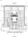
FIG. 1 is a cross-sectional view of a vacuum pump to which the present invention is applied; -
FIG. 2 is a diagram illustrating a flow of an inert gas in the vacuum pump shown inFIG. 1 ; -
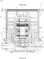
FIG. 3 is a diagram showing a first embodiment of a vacuum pump according to the present invention; -
FIG. 4 is an enlarged view of a main part of the vacuum pump shown inFIG. 3 ; -
FIGS. 5A to 5C are diagrams showing other examples of a flow-disturbing portion that disturbs the flow of inert gas used in the vacuum pump shown inFIG. 3 ; -
FIG. 6 is an enlarged view of a main part of a second embodiment of a vacuum pump according to the present invention; -
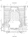
FIG. 7 is a diagram showing a third embodiment of a vacuum pump according to the present invention; -
FIGS. 8A and 8B are diagrams showing examples of grooves used in the vacuum pump shown inFIG. 7 ; -
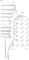
FIG. 9 is a diagram showing another example of a flow-disturbing portion that disturbs the flow of inert gas used in the vacuum pump shown inFIG. 7 ; and -
FIG. 10 is an enlarged view of a main part of a fourth embodiment of a vacuum pump according to the present invention. - Referring to the attached drawings, embodiments of the present invention are now described in detail.
-
FIG. 1 is a cross-sectional view of a vacuum pump to which the present invention is applied. The vacuum pump P shown inFIG. 1 may be used as a gas exhaust means for a process chamber or other enclosed chamber in a semiconductor manufacturing apparatus, a flat panel display manufacturing apparatus, or a solar panel manufacturing apparatus. - The vacuum pump P includes, in a casing 1, a blade exhaust portion Pt, which uses
rotor blades 13 andstator blades 14 to exhaust gas, a thread groove exhaust portion Ps, which uses athread groove 16 to exhaust gas, and the driving systems of these portions. - The casing 1 has the shape of a cylinder with a closed end and includes a
cylindrical pump case 1A and acylindrical pump base 1B with a closed end, which are coupled together with bolts in the axial direction of the cylinder. The upper end of thepump case 1A opens as agas inlet port 2, and the lower end of thepump base 1B has agas outlet port 3. - The
gas inlet port 2 is connected to an enclosed chamber (not shown) having a high vacuum, such as a process chamber of a semiconductor manufacturing apparatus, with bolts (not shown) provided on aflange 1C at the upper edge of thepump case 1A. Thegas outlet port 3 communicates with an auxiliary pump (not shown). - A
cylindrical stator column 4, which contains various electrical components, is provided in the central portion of thepump case 1A. Thestator column 4 extends upright with its lower end fixed to thepump base 1B with screws. - A
rotor shaft 5, which is provided inside thestator column 4, is oriented such that its upper end faces toward thegas inlet port 2 and its lower end faces toward thepump base 1B. Furthermore, the upper end of therotor shaft 5 extends upward beyond the upper end surface of thecylindrical stator column 4. - The
rotor shaft 5 is rotatably levitated and supported in the radial and axial directions by the magnetic forces of radialmagnetic bearings 10 and an axialmagnetic bearing 11, and is driven and rotated by amotor 20. Protective bearings B1 and B2 are provided at the upper and lower ends of therotor shaft 5. - A
rotor 6 is provided outward of thestator column 4. Therotor 6 has the shape of a cylinder surrounding the outer circumference of thestator column 4, is integral with therotor shaft 5, and is configured to rotate in thepump case 1A with therotor shaft 5 as the rotation axis. - As such, in the vacuum pump P of
FIG. 1 , therotor shaft 5, the radialmagnetic bearings rotor 6 so as to be rotatable about its axis. Furthermore, since therotor 6 rotates integrally with therotor shaft 5, themotor 20, which drives and rotates therotor shaft 5, functions as a driving means that drives and rotates therotor 6. - Since the detailed configurations of the protective bearings B1 and B2, the radial
magnetic bearings 10, and the axialmagnetic bearing 11 are well known in the art, the descriptions thereof are omitted. - In the vacuum pump P of
FIG. 1 , the section upstream of the approximate midpoint of the rotor 6 (the range from the approximate midpoint of therotor 6 to the end of therotor 6 including the gas inlet port 2) functions as the blade exhaust portion Pt. The detailed configurations of the blade exhaust portion Pt are now described. - The
rotor 6 includes a plurality ofrotor blades 13 formed integrally with the outer circumference surface of the section of therotor 6 on the upstream side of the approximate midpoint of therotor 6. Therotor blades 13 extend from the outer circumference surface of therotor 6 in the radial direction of therotor 6. Therotor blades 13 are arranged radially about the rotation axis of the rotor 6 (rotor shaft 5) or the axis of the casing 1 (hereinafter referred to as a "pump axis"). Therotor blades 13 are formed integrally with the outer diameter processing portion of therotor 6 by a cutting process and inclined at an optimum angle to exhaust gas molecules. - A plurality of
stator blades 14 are provided on the inner circumference surface of thepump case 1A. Thestator blades 14 extend from the inner circumference surface of thepump case 1A toward the outer circumference surface of therotor 6 and are arranged radially about the pump axis. As with therotor blades 13, thestator blades 14 are also inclined at an optimum angle to exhaust gas molecules. - In the vacuum pump P of
FIG. 1 , therotor blades 13 and thestator blades 14 described above are alternately arranged in multiple stages along the pump axis, thereby forming the multi-stage blade exhaust portion Pt. - In the blade exhaust portion Pt thus configured, the
rotor shaft 5, therotor 6, and therotor blades 13 rotate together at high speed when themotor 20 is activated, and theuppermost rotor blade 13 applies a downward momentum to the gas molecules entering through thegas inlet port 2. The gas molecules having this downward momentum are transferred to therotor blade 13 in the next stage by thestator blade 14. The application of the momentum to the gas molecules and the transfer action are repeated in multiple stages, causing the gas molecules to move sequentially from thegas inlet port 2 to the downstream side of therotor 6 and be exhausted. - In the vacuum pump P of
FIG. 1 , the section downstream of the approximate midpoint of the rotor 6 (the range from the approximate midpoint of therotor 6 to the end of therotor 6 including the gas outlet port 3) functions as the thread groove exhaust portion (thread groove pump) Ps. The detailed configurations of the thread groove exhaust portion Ps are now described. - The section of the
rotor 6 on the downstream side of the approximate midpoint of therotor 6 is configured to rotate as a rotation member of the thread groove exhaust portion Ps and is placed inward of a thread grooveexhaust portion stator 15. - The thread groove
exhaust portion stator 15 is a cylindrical fixed member and surrounds the outer circumference of the rotor 6 (the section downstream of the approximate midpoint of the rotor 6). Thepump base 1B supports the lower end of the thread grooveexhaust portion stator 15. - The inner circumference of the thread groove
exhaust portion stator 15 has athread groove 16, which decreases in depth toward the lower end and thus forms the shape of a cone tapering downward. Thethread groove 16 is engraved in the shape of a spiral from the upper end to the lower end of the thread grooveexhaust portion stator 15. Thethread groove 16 forms a spiral thread groove exhaust passage S between therotor 6 and the thread grooveexhaust portion stator 15. Although not shown, the thread groove exhaust passage S may also be provided by forming thethread groove 16 described above in the inner circumference surface of therotor 6. - In the thread groove exhaust portion Ps, the drag effect at the
thread groove 16 and the outer circumference surface of therotor 6 transfers the gas while compressing it. To this end, the depth of thethread groove 16 is deepest at the upstream inlet of the thread groove exhaust passage S (the passage open end that is closer to the gas inlet port 2) and shallowest at the downstream outlet (the passage open end that is closer to the gas outlet port 3). - The upstream inlet of the thread groove exhaust passage S communicates with the gap formed downstream of the blade in the lowermost stage (the
stator blade 14 in the lowermost stage in the example ofFIG. 1 ) among therotor blades 13 and thestator blades 14 in multiple stages, whereas the downstream outlet of the thread groove exhaust passage S communicates with thegas outlet port 3. - The gas molecules that have been transferred by the exhaust action of the blade exhaust portion Pt described above and reached the blade in the lowermost stage (the
rotor blade 13 in the example ofFIG. 1 ) enter the thread groove exhaust passage S through the upstream inlet of the thread groove exhaust passage S. The effect caused by the rotation of therotor 6, that is, the drag effect at the outer circumference surface of therotor 6 and thethread groove 16, compresses the entering gas molecules so that their transitional flow is converted into a viscous flow while moving toward thegas outlet port 3. Eventually, the gas molecules are exhausted to the outside through an auxiliary pump (not shown). -
FIG. 2 is a diagram illustrating a flow of inert gas (purge gas) according to the present invention used in the vacuum pump shown inFIG. 1 . - As described above, the
cylindrical rotor 6 surrounds the outer circumference of thecylindrical stator column 4 containing various electrical components. A purge gas PG is injected into thepump case 1A from the outside through a purgegas injection passage 30, flows through the passage providing communication between the gap between the outer wall of therotor shaft 5 and the inner wall of thestator column 4 and the gap between the outer wall of thestator column 4 and the inner wall of therotor 6, and is exhausted from thegas outlet port 3. - The purge gas PG may be a gas having a high thermal conductivity, such as nitrogen gas. The compression heat accumulating in the
rotor 6 is dissipated from the inner wall surface of therotor 6 to the outer wall surface of thestator column 4 via the purge gas PG. Therotor 6 and therotor blades 13 are thus cooled. - In a conventional configuration, the purge gas PG flowing through the gap between the outer wall of the
stator column 4 and the inner wall of therotor 6 forms a laminar flow. As such, the sufficient cooling effect of therotor 6 and therotor blades 13 cannot be achieved even when a gas with a high thermal conductivity such as nitrogen gas is used as the purge gas PG. - In this respect, the vacuum pump of the present invention has a flow-disturbing portion in the flow passage of the purge gas PG to disturb the flow of the purge gas PG. The flow-disturbing portion converts the flow of the purge gas PG from a laminar flow into a turbulent flow as much as possible to improve the cooling effect for the
rotor 6 and therotor blades 13. - Various embodiments of a vacuum pump of the present invention are now described in detail.
-
FIG. 3 is a diagram showing an embodiment of a vacuum pump according to the present invention, andFIG. 4 is an enlarged view of a main part of the vacuum pump shown inFIG. 3 . The vacuum pump of the first embodiment shown inFIGS. 3 and4 includes a plurality ofprojections 41 on the outer circumference surface (circumference surface) of thestator column 4. Other configurations are the same as those described with reference toFIGS. 1 and2 . - In this configuration, the purge gas PG flowing through the gap between the outer wall of the
stator column 4 and the inner wall of therotor 6 collides with theprojections 41, so that its flow is disturbed. As a result, the flow of purge gas through the gap between the outer wall of thestator column 4 and the inner wall of therotor 6 is converted from a laminar flow into a turbulent flow or a flow that resembles a turbulent flow. Even when the flow that has been converted into a flow resembling a turbulent flow byprojections 41 on the upstream side is converted again into a laminar flow on the downstream side,other projections 41 can again convert this flow into a flow resembling a turbulent flow. That is, providing the plurality ofprojections 41 advantageously forms a flow resembling a turbulent flow in a large area. - When the flow of purge gas PG through the gap between the outer wall of the
stator column 4 and the inner wall of therotor 6 is converted into a turbulent flow or a flow resembling a turbulent flow, the convective heat transfer by the purge gas PG is significantly improved, achieving the efficient heat dissipation of the rotor without changing the material or structure of stator blades or rotor blades. - The example shown in
FIGS. 3 and4 uses theprojection 41 that is a plate having the shape of a rectangular solid. However, instead of thisprojection 41, aprojection 411 that is a plate having a bowl-shaped cross-section recessed in the flow direction of the purge gas PG shown inFIG. 5A , aprojection 412 that is a plate having an inverted bowl-shaped cross-section bulging in the flow direction of the purge gas PG shown inFIG. 5B , or aprojection 413 that is a plate having a bow-shaped cross-section bulging in the flow direction of the purge gas PG shown inFIG. 5C may be used to form a similar configuration. - The embodiment shown in
FIGS. 3 and4 includes a plurality ofprojections 41. However, forming only oneprojection 41 can still disturb the flow of the purge gas PG to some extent, improving the convective heat transfer by the purge gas PG. -
FIG. 6 is an enlarged view of a main part of a second embodiment of a vacuum pump according to the present invention and corresponds to the enlarged view of the main part of the vacuum pump ofFIG. 4 . - The second embodiment shown in
FIG. 6 includeshemispherical protrusions 42, in place of theprojections 41 shown inFIG. 4 . In the vacuum pump of the second embodiment shown inFIG. 6 , the purge gas PG flowing through the gap between the outer wall of thestator column 4 and the inner wall of therotor 6 collides with thesehemispherical protrusions 42, so that its flow is disturbed. As a result, the flow of purge gas through the gap between the outer wall of thestator column 4 and the inner wall of therotor 6 is converted from a laminar flow into a turbulent flow or a flow that resembles a turbulent flow. - Accordingly, in the vacuum pump of the second embodiment, the convective heat transfer by the purge gas PG flowing through the gap between the outer wall of the
stator column 4 and the inner wall of therotor 6 is also significantly improved, achieving the efficient heat dissipation of the rotor without changing the material or structure of stator blades or rotor blades. -
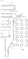
FIG. 7 is a diagram showing a third embodiment of a vacuum pump according to the present invention. - The vacuum pump of the third embodiment shown in
FIG. 7 includes a plurality ofgrooves 43 formed in the outer circumference surface (circumference surface) of thestator column 4. Other configurations are the same as those described with reference toFIGS. 1 and2 . -
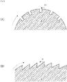
FIG. 8A is a cross-sectional view of thestator column 4 showing the shape of thegrooves 43 shown inFIG. 7 . As shown inFIG. 8A , eachgroove 43 has a rectangular shape as viewed in a cross-section perpendicular to the axis of thestator column 4. Thesegrooves 43 also disturb the flow of purge gas through the gap between the outer wall of thestator column 4 and the inner wall of therotor 6, thereby converting the flow from a laminar flow into a turbulent flow or a flow resembling a turbulent flow. Accordingly, the convective heat transfer by the purge gas PG flowing through the gap between the outer wall of thestator column 4 and the inner wall of therotor 6 is also significantly improved, achieving the efficient heat dissipation of the rotor without changing the material or structure of stator blades or rotor blades. - The direction of purge gas flow at a predetermined angle results from the relationship between the velocity component in the axial direction of the
stator column 4, which depends on the difference in pressure between the upstream side and the downstream side, and the velocity component in the tangential direction of rotation caused by the fluid drag effect at the inner circumference surface of therotor 6. - The
grooves 43 shown inFIG. 7 may form a sawtooth shape like thegrooves 44 shown inFIG. 8B . Thegrooves 44 form a sawtooth shape including inclined sections rising in the flow direction of inert gas as viewed in a cross-section perpendicular to the axis of thestator column 4. Thesegrooves 44 forming a sawtooth shape also disturb the flow of purge gas through the gap between the outer wall of thestator column 4 and the inner wall of therotor 6, thereby converting the flow from a laminar flow into a turbulent flow or a flow resembling a turbulent flow. Accordingly, the convective heat transfer by the purge gas PG flowing through the gap between the outer wall of thestator column 4 and the inner wall of therotor 6 is also significantly improved, achieving the efficient heat dissipation of the rotor without changing the material or structure of stator blades or rotor blades. - In the third embodiment shown in
FIG. 7 , thegrooves 43 extend in the axial direction of thestator column 4. However, as shown inFIG. 9 , the circumference surface of thestator column 4 may includegrooves 45 that extend in a direction that disturbs the flow of purge gas PG and is inclined at a predetermined angle with respect to the axial direction of thestator column 4. Thegrooves 45 disturb the flow of purge gas through the gap between the outer wall of thestator column 4 and the inner wall of therotor 6, thereby converting the flow from a laminar flow into a turbulent flow or a flow resembling a turbulent flow. This significantly improves the convective heat transfer by the purge gas PG flowing through the gap between the outer wall of thestator column 4 and the inner wall of therotor 6, achieving the efficient heat dissipation of the rotor without changing the material or structure of stator blades or rotor blades. - The
grooves 45 may be shaped such that each groove has a rectangular shape as viewed in a cross-section perpendicular to the axis of thestator column 4 as shown inFIG. 8A , or such that the grooves form a sawtooth shape including inclined sections rising in the flow direction of inert gas as viewed in a cross-section perpendicular to the axis of thestator column 4 as shown inFIG. 8B . -
FIG. 10 is an enlarged view of a main part of a fourth embodiment of a vacuum pump according to the present invention and corresponds to the enlarged view of the main part of the vacuum pump ofFIG. 6 . - The vacuum pump shown in
FIG. 6 includes a plurality ofhemispherical protrusions 42 formed on the surface of thestator column 4. In contrast, the fourth embodiment shown inFIG. 10 includes a plurality ofhemispherical recesses 46 in the surface of thestator column 4. Other configurations are the same as those described with reference toFIG. 6 . - In this configuration including the
hemispherical recesses 46 in the surface of thestator column 4, the flow of purge gas through the gap between the outer wall of thestator column 4 and the inner wall of therotor 6 is also disturbed and thus converted from a laminar flow into a turbulent flow or a flow resembling a turbulent flow. This significantly improves the convective heat transfer by the purge gas PG flowing through the gap between the outer wall of thestator column 4 and the inner wall of therotor 6, achieving the efficient heat dissipation of the rotor without changing the material or structure of stator blades or rotor blades. - In the embodiments described above, the flow-disturbing portion that disturbs the flow of the purge gas PG includes the
projections protrusions 42, thegrooves recesses 46 formed on or in the circumference surface of thestator column 4. However, the flow-disturbing portion that disturbs the flow of the purge gas PG may be formed on or in the inner wall of therotor 6 corresponding to theprojections protrusions 42, thegrooves recesses 46. - In this configuration, the flow of purge gas through the gap between the outer wall of the
stator column 4 and the inner wall of therotor 6 is also disturbed and thus converted from a laminar flow into a turbulent flow or a flow resembling a turbulent flow. This significantly improves the convective heat transfer by the purge gas PG flowing through the gap between the outer wall of thestator column 4 and the inner wall of therotor 6, achieving the efficient heat dissipation of the rotor without changing the material or structure of stator blades or rotor blades. - In the above embodiment, as the flow-disturbing portion that disturbs the flow of the purge gas PG, a plurality of projections or grooves are formed on or in the surface of the
stator column 4 or the inner circumference surface of therotor 6. Alternatively, the surface of thestator column 4 or the inner circumference surface of therotor 6 may be roughened by surface treatment or the like so as to disturb the flow of the purge gas PG. - Furthermore, the flow-disturbing portion provided on the surface of the
stator column 4 or the inner circumference surface of therotor 6 may have any shape as long as it disturbs the flow of the purge gas PG, and the number thereof and the region in which the flow-disturbing portion is formed may be modified in various manners. - It should be noted that the present invention is not limited to the above-described embodiments, and various modifications can be made by the ordinary creative ability of those skilled in the art within the scope of the technical idea of the present invention.
-
- 1
- Pump casing
- 1A
- Pump case
- 1B
- Pump base
- 1C
- Flange
- 2
- Gas inlet port
- 3
- Gas outlet port
- 4
- Stator column
- 5
- Rotor shaft
- 6
- Rotor
- 7
- Boss hole
- 9
- Shoulder
- 10
- Radial magnetic bearing
- 11
- Axial magnetic bearing
- 13
- Rotor blade
- 14
- Stator blade
- 15
- Thread groove exhaust portion stator
- 16
- Thread groove
- 20
- Motor
- 30
- Purge gas injection passage
- 41, 411, 412, 413
- Projection
- 42
- Protrusion
- 43, 44, 45
- Groove
- 46
- Recess
- B1, B2
- Protective bearing
- P
- Vacuum pump
- Pt
- Blade exhaust portion
- Ps
- Thread groove exhaust portion
- S
- Thread groove exhaust passage
Claims (12)
- A vacuum pump comprising a casing having an inlet port and an outlet port and a rotor configured to rotate in the casing, the vacuum pump being configured to exhaust gas from the inlet port to the outlet port by rotation of the rotor, whereinthe rotor substantially has a shape of a cylinder,an inert gas flows between an inner circumference surface of the rotor and a fixed portion facing at least a part of the inner surface of the rotor, anda flow-disturbing portion is provided in a flow passage of the inert gas to disturb a flow of the inert gas.
- The vacuum pump according to claim 1, wherein the flow-disturbing portion includes one or more projecting portions on a circumference surface of the fixed portion or the inner circumference surface of the rotor.
- The vacuum pump according to claim 2, wherein each of the projecting portions has a shape of a plate.
- The vacuum pump according to claim 2 or 3, wherein each of the projecting portions has a portion that is curved with respect to a direction of the flow of the inert gas.
- The vacuum pump according to any one of claims 2 to 4, wherein each of the projecting portions is inclined at a predetermined angle with respect to an axial direction of the circumference surface of the fixed portion or the inner circumference surface of the rotor.
- The vacuum pump according to any one of claims 2 to 5, wherein the projecting portions are spaced apart from one another in a direction that is inclined at a predetermined angle with respect to an axial direction of the circumference surface of the fixed portion or the inner circumference surface of the rotor.
- The vacuum pump according to claim 1, wherein the flow-disturbing portion includes one or more recesses in a circumference surface of the fixed portion or the inner circumference surface of the rotor.
- The vacuum pump according to claim 7, wherein each of the recesses is a groove extending in an axial direction of the circumference surface of the fixed portion or the inner circumference surface of the rotor.
- The vacuum pump according to claim 7 or 8, wherein each of the recesses is inclined at a predetermined angle with respect to an axial direction of the circumference surface of the fixed portion or the inner circumference surface of the rotor.
- The vacuum pump according to any one of claims 7 to 9, wherein the recesses are spaced apart from one another in a direction that is inclined at a predetermined angle with respect to an axial direction of the circumference surface of the fixed portion or the inner circumference surface of the rotor.
- A vacuum pump component to be used in a vacuum pump, wherein the vacuum pump includes a casing having an inlet port and an outlet port and a rotor configured to rotate in the casing, the vacuum pump is configured to exhaust gas from the inlet port to the outlet port by rotation of the rotor, the rotor substantially has a shape of a cylinder, an inert gas flows between an inner circumference surface of the rotor and a fixed portion facing at least a part of the inner circumference surface of the rotor, a flow-disturbing portion is provided in a flow passage of the inert gas to disturb a flow of the inert gas,the vacuum pump component corresponds to the fixed portion, anda circumference surface facing the inner circumference surface of the rotor includes the flow-disturbing portion configured to disturb the flow of the inert gas.
- A vacuum pump component to be used in a vacuum pump, wherein the vacuum pump includes a casing having an inlet port and an outlet port and a rotor configured to rotate in the casing, the vacuum pump is configured to exhaust gas from the inlet port to the outlet port by rotation of the rotor, the rotor substantially has a shape of a cylinder, an inert gas flows between an inner circumference surface of the rotor and a fixed portion facing at least a part of the inner circumference surface of the rotor, a flow-disturbing portion is provided in a flow passage of the inert gas to disturb a flow of the inert gas,the vacuum pump component corresponds to the rotor, andthe inner circumference surface facing the fixed portion includes the flow-disturbing portion configured to disturb the flow of the inert gas.
Applications Claiming Priority (2)
| Application Number | Priority Date | Filing Date | Title |
|---|---|---|---|
| JP2020049766A JP7463150B2 (en) | 2020-03-19 | 2020-03-19 | Vacuum pumps and vacuum pump parts |
| PCT/JP2021/009920 WO2021187336A1 (en) | 2020-03-19 | 2021-03-11 | Vacuum pump and vacuum pump component |
Publications (2)
| Publication Number | Publication Date |
|---|---|
| EP4123181A1 true EP4123181A1 (en) | 2023-01-25 |
| EP4123181A4 EP4123181A4 (en) | 2024-04-17 |
Family
ID=77772052
Family Applications (1)
| Application Number | Title | Priority Date | Filing Date |
|---|---|---|---|
| EP21772538.1A Withdrawn EP4123181A4 (en) | 2020-03-19 | 2021-03-11 | VACUUM PUMP AND VACUUM PUMP COMPONENTS |
Country Status (7)
| Country | Link |
|---|---|
| US (1) | US20230114695A1 (en) |
| EP (1) | EP4123181A4 (en) |
| JP (1) | JP7463150B2 (en) |
| KR (1) | KR20220150287A (en) |
| CN (1) | CN115176089A (en) |
| IL (1) | IL296414A (en) |
| WO (1) | WO2021187336A1 (en) |
Families Citing this family (1)
| Publication number | Priority date | Publication date | Assignee | Title |
|---|---|---|---|---|
| JP2025001084A (en) * | 2023-06-20 | 2025-01-08 | Toyo Tire株式会社 | Pneumatic tire |
Family Cites Families (15)
| Publication number | Priority date | Publication date | Assignee | Title |
|---|---|---|---|---|
| DE2408256A1 (en) * | 1974-02-21 | 1975-09-04 | Leybold Heraeus Gmbh & Co Kg | Turbo molecular vacuum pump with first stage auxiliary pump - has gas supply for scavenging rotor bearing chamber |
| JPS6143298A (en) * | 1984-08-06 | 1986-03-01 | Osaka Shinku Kiki Seisakusho:Kk | Gas purge device for molecular pump |
| JPH029994A (en) * | 1988-06-28 | 1990-01-12 | Daikin Ind Ltd | Vortex turbomachinery |
| US5020969A (en) * | 1988-09-28 | 1991-06-04 | Hitachi, Ltd. | Turbo vacuum pump |
| JP2928615B2 (en) * | 1990-09-28 | 1999-08-03 | 株式会社日立製作所 | Turbo vacuum pump |
| JP3794775B2 (en) * | 1997-03-19 | 2006-07-12 | 株式会社大阪真空機器製作所 | Molecular pump |
| JP3819267B2 (en) * | 2001-08-27 | 2006-09-06 | 株式会社荏原製作所 | Vacuum pump imbalance correction method, vacuum pump |
| JP4156830B2 (en) * | 2001-12-13 | 2008-09-24 | エドワーズ株式会社 | Vacuum pump |
| JP3909591B2 (en) * | 2003-01-14 | 2007-04-25 | アネスト岩田株式会社 | Scroll fluid machinery |
| JP2004278500A (en) | 2003-03-19 | 2004-10-07 | Boc Edwards Kk | Molecular pump |
| GB0424199D0 (en) * | 2004-11-01 | 2004-12-01 | Boc Group Plc | Vacuum pump |
| JP2007198153A (en) * | 2006-01-24 | 2007-08-09 | Anest Iwata Corp | Scroll fluid machine |
| NO330109B1 (en) * | 2008-02-07 | 2011-02-21 | Statoilhydro Asa | Rotor storage system in rotary machines |
| US20110200460A1 (en) * | 2008-08-19 | 2011-08-18 | Manabu Nonaka | Vacuum pump |
| JP2014037809A (en) * | 2012-08-17 | 2014-02-27 | Shimadzu Corp | Vacuum pump and operation method of vacuum pump |
-
2020
- 2020-03-19 JP JP2020049766A patent/JP7463150B2/en active Active
-
2021
- 2021-03-11 IL IL296414A patent/IL296414A/en unknown
- 2021-03-11 WO PCT/JP2021/009920 patent/WO2021187336A1/en not_active Ceased
- 2021-03-11 KR KR1020227028232A patent/KR20220150287A/en active Pending
- 2021-03-11 US US17/906,129 patent/US20230114695A1/en not_active Abandoned
- 2021-03-11 EP EP21772538.1A patent/EP4123181A4/en not_active Withdrawn
- 2021-03-11 CN CN202180019034.3A patent/CN115176089A/en not_active Withdrawn
Also Published As
| Publication number | Publication date |
|---|---|
| JP7463150B2 (en) | 2024-04-08 |
| US20230114695A1 (en) | 2023-04-13 |
| CN115176089A (en) | 2022-10-11 |
| EP4123181A4 (en) | 2024-04-17 |
| IL296414A (en) | 2022-11-01 |
| WO2021187336A1 (en) | 2021-09-23 |
| JP2021148088A (en) | 2021-09-27 |
| KR20220150287A (en) | 2022-11-10 |
Similar Documents
| Publication | Publication Date | Title |
|---|---|---|
| US4734015A (en) | Axial-flow fan | |
| US4917572A (en) | Centrifugal blower with axial clearance | |
| JP3961155B2 (en) | Vacuum pump | |
| EP2480793B1 (en) | Rotodynamic machine | |
| KR20000062974A (en) | Turbo-molecular pump | |
| CN105358835A (en) | Vacuum pump | |
| EP3388681B1 (en) | Linked-type screw groove spacer, and vacuum pump | |
| EP3088744B1 (en) | Vacuum exhaust mechanism and compound vacuum pump | |
| JP5768670B2 (en) | Turbo molecular pump device | |
| CN111379713B (en) | vacuum pump | |
| US6409468B1 (en) | Turbo-molecular pump | |
| US20230114695A1 (en) | Vacuum pump and vacuum pump component | |
| US6179573B1 (en) | Vacuum pump with inverted motor | |
| KR102777799B1 (en) | Radial Force Support Apparatus | |
| US7938619B2 (en) | Turbo vacuum pump | |
| JP4898076B2 (en) | Pump as a bypass pump | |
| CN113840985A (en) | Vacuum pump and connecting type thread groove spacer | |
| EP3610155B1 (en) | Magnetic coupling assembly | |
| JPH0219694A (en) | Oil-free vacuum pump | |
| CN201310490Y (en) | Electronic radiating fan | |
| TW202536299A (en) | Vacuum pump | |
| EP2059681B1 (en) | Vacuum pumps with improved pumping channel configurations | |
| US7347252B2 (en) | Centrifugal impeller | |
| US8961104B2 (en) | Vacuum pump | |
| JP2004278500A (en) | Molecular pump |
Legal Events
| Date | Code | Title | Description |
|---|---|---|---|
| STAA | Information on the status of an ep patent application or granted ep patent |
Free format text: STATUS: THE INTERNATIONAL PUBLICATION HAS BEEN MADE |
|
| PUAI | Public reference made under article 153(3) epc to a published international application that has entered the european phase |
Free format text: ORIGINAL CODE: 0009012 |
|
| STAA | Information on the status of an ep patent application or granted ep patent |
Free format text: STATUS: REQUEST FOR EXAMINATION WAS MADE |
|
| 17P | Request for examination filed |
Effective date: 20220928 |
|
| AK | Designated contracting states |
Kind code of ref document: A1 Designated state(s): AL AT BE BG CH CY CZ DE DK EE ES FI FR GB GR HR HU IE IS IT LI LT LU LV MC MK MT NL NO PL PT RO RS SE SI SK SM TR |
|
| DAV | Request for validation of the european patent (deleted) | ||
| DAX | Request for extension of the european patent (deleted) | ||
| A4 | Supplementary search report drawn up and despatched |
Effective date: 20240315 |
|
| RIC1 | Information provided on ipc code assigned before grant |
Ipc: F04D 25/06 20060101ALI20240311BHEP Ipc: F04D 19/04 20060101AFI20240311BHEP |
|
| STAA | Information on the status of an ep patent application or granted ep patent |
Free format text: STATUS: THE APPLICATION HAS BEEN WITHDRAWN |
|
| 18W | Application withdrawn |
Effective date: 20250604 |