EP4123164B1 - Vertical axis wind turbine - Google Patents
Vertical axis wind turbine Download PDFInfo
- Publication number
- EP4123164B1 EP4123164B1 EP22186179.2A EP22186179A EP4123164B1 EP 4123164 B1 EP4123164 B1 EP 4123164B1 EP 22186179 A EP22186179 A EP 22186179A EP 4123164 B1 EP4123164 B1 EP 4123164B1
- Authority
- EP
- European Patent Office
- Prior art keywords
- blade
- turbine
- support frame
- shaft
- blades
- Prior art date
- Legal status (The legal status is an assumption and is not a legal conclusion. Google has not performed a legal analysis and makes no representation as to the accuracy of the status listed.)
- Active
Links
Images



Classifications
-
- F—MECHANICAL ENGINEERING; LIGHTING; HEATING; WEAPONS; BLASTING
- F03—MACHINES OR ENGINES FOR LIQUIDS; WIND, SPRING, OR WEIGHT MOTORS; PRODUCING MECHANICAL POWER OR A REACTIVE PROPULSIVE THRUST, NOT OTHERWISE PROVIDED FOR
- F03D—WIND MOTORS
- F03D3/00—Wind motors with rotation axis substantially perpendicular to the air flow entering the rotor
- F03D3/06—Rotors
- F03D3/062—Rotors characterised by their construction elements
- F03D3/066—Rotors characterised by their construction elements the wind engaging parts being movable relative to the rotor
- F03D3/067—Cyclic movements
- F03D3/068—Cyclic movements mechanically controlled by the rotor structure
-
- F—MECHANICAL ENGINEERING; LIGHTING; HEATING; WEAPONS; BLASTING
- F05—INDEXING SCHEMES RELATING TO ENGINES OR PUMPS IN VARIOUS SUBCLASSES OF CLASSES F01-F04
- F05B—INDEXING SCHEME RELATING TO WIND, SPRING, WEIGHT, INERTIA OR LIKE MOTORS, TO MACHINES OR ENGINES FOR LIQUIDS COVERED BY SUBCLASSES F03B, F03D AND F03G
- F05B2240/00—Components
- F05B2240/20—Rotors
- F05B2240/30—Characteristics of rotor blades, i.e. of any element transforming dynamic fluid energy to or from rotational energy and being attached to a rotor
- F05B2240/31—Characteristics of rotor blades, i.e. of any element transforming dynamic fluid energy to or from rotational energy and being attached to a rotor of changeable form or shape
- F05B2240/311—Characteristics of rotor blades, i.e. of any element transforming dynamic fluid energy to or from rotational energy and being attached to a rotor of changeable form or shape flexible or elastic
-
- Y—GENERAL TAGGING OF NEW TECHNOLOGICAL DEVELOPMENTS; GENERAL TAGGING OF CROSS-SECTIONAL TECHNOLOGIES SPANNING OVER SEVERAL SECTIONS OF THE IPC; TECHNICAL SUBJECTS COVERED BY FORMER USPC CROSS-REFERENCE ART COLLECTIONS [XRACs] AND DIGESTS
- Y02—TECHNOLOGIES OR APPLICATIONS FOR MITIGATION OR ADAPTATION AGAINST CLIMATE CHANGE
- Y02E—REDUCTION OF GREENHOUSE GAS [GHG] EMISSIONS, RELATED TO ENERGY GENERATION, TRANSMISSION OR DISTRIBUTION
- Y02E10/00—Energy generation through renewable energy sources
- Y02E10/70—Wind energy
- Y02E10/74—Wind turbines with rotation axis perpendicular to the wind direction
Definitions
- the present invention concerns, in general, the technical field of wind turbines. More specifically, the present invention concerns a vertical axis wind turbine provided with a system for varying the geometry of the blades, so as to increase the conversion efficiency of the kinetic energy of the wind into mechanical energy for subsequent conversion into electric energy by a generator.
- a wind turbine is an electro-mechanical machine built to exploit/convert the kinetic energy of the wind, or wind energy, into electric energy via the use of a rotor comprising two or more blades.
- the production of electric energy by a wind turbine passes through a first phase, in which the kinetic energy of the air mass is converted into mechanical energy of the blades, and a second phase, in which the mechanical energy of the blades is converted into electric energy by a generator.
- Wind turbines are usually classified into Horizontal Axis Wind Turbines (HWAT) and Vertical Axis Wind Turbines (VAWT), with reference to the blade rotation axis, which can be parallel or perpendicular to the ground.
- HWAT Horizontal Axis Wind Turbines
- VAWT Vertical Axis Wind Turbines
- Horizontal axis wind turbines were the first to be exploited in history (they were used, for example, to drive windmills or water pumping systems) and are still the most widely used. They typically comprise a support tower, a rotor, which is formed of a plurality of blades (usually three blades), a hub and a shaft, and a nacelle, which contains a generator, a gearbox and one or more control devices.
- Horizontal axis wind turbines can be either upwind, in which case the wind encounters the rotor before the tower, or downwind.
- Upwind turbines offer greater efficiency since there is no aerodynamic interference with the tower but, on the other hand, they have the drawback of not being self-aligning with respect to the wind direction and therefore require a directional fin or a yaw system.
- Downwind turbines on the other hand, are negatively affected by the interaction between tower and rotor, but they are intrinsically self-aligning and can use a flexible rotor to withstand strong winds.
- Horizontal axis wind turbines have a high wind to electric energy conversion efficiency. Furthermore, they operate with a very low torque and this contributes significantly to improving the overall reliability of the moving parts.
- the intensity of the wind at ground level is lower than the speed of the same wind current at altitude and, simultaneously, the turbulence intensity is higher. This results in less energy available for conversion by the rotor into power available to the rotation shaft.
- a Savonius turbine is a "resistance" type vertical axis wind turbine, comprising two or four semi-cylindrical vertical blades which are fixed, opposite one another, to a shaft. When the wind impacts one of the semi-cylindrical blades, it rotates the shaft. In this way, while the confined flow that strikes a semi-cylindrical blade decreases, the opposite semi-cylindrical blade sees an increase in said confined flow. In other words the blades encounter less resistance when they move against the wind than when they move with the wind and this difference in resistance causes rotation of the turbine.
- the main drawback of said type of wind generator is that of having a half-cylinder moving against the wind, which limits the torque that can be produced, with consequent reduction in performance.
- the Darrieus turbines are "lift" type vertical axis wind turbines, in which the surfaces of the blades arranged in the direction of the wind have a wing profile able to generate a different pressure distribution along the blade and therefore a torque available to the rotation axis.
- the Darrieus turbine offers greater efficiency because it limits friction losses.
- the Darrieus turbine is not able to start up independently since, regardless of the wind speed, the starting torque is null. This type of turbine therefore requires an auxiliary device.
- a possible solution is represented by the hybrid Darrieus-Savonius turbine, in which the starting torque is provided by the Savonius turbine, coaxial with and internal to the Darrieus turbine. From the above, it can be seen that, despite their numerous advantages, vertical axis wind turbines have the drawback of having a limited conversion efficiency of the wind energy into electric energy, which can be up to 50% lower than the conversion efficiency of horizontal axis wind turbines. Examples of prior art solutions are available in documents EP 3 702 610 A1 , KR 2012 0131804 A , DE 10 2012 019268 A1 .
- the main object of the present invention is therefore to provide a vertical axis wind turbine configured so as to increase the conversion efficiency of the wind energy into electric energy.
- a further object of the present invention is to provide a vertical axis wind turbine configured to self-align with respect to the direction of the wind.
- a further object of the present invention is to provide a vertical axis wind turbine, the blades of which withstand the wind that impacts on them, without being damaged over time.
- Yet another object of the present invention is to provide a vertical axis wind turbine configured so as to present a solid structure and therefore able to operate also in conditions of high intensity wind.
- a further object of the present invention is to provide a vertical axis wind turbine with a simplified structure, so as to limit production and maintenance costs.
- the invention therefore concerns a vertical axis wind turbine comprising a support base, a shaft extending centrally from the support base, a support frame for a plurality of blades, mounted on the base rotatable with the shaft, and a control frame for the plurality of blades, mounted on the shaft, above the blade support frame.
- Each blade of the plurality of blades comprises a first half-blade and a second half-blade supported by the blade support frame.
- the turbine is characterized in that the blade control frame comprises a control element mounted rotatable on the shaft, a pin extending from the control element in an eccentric position with respect to the shaft, a plurality of connecting rods, one for each blade, rotatably supported by the pin, and a directional deflector extending from the pin and rotatable integrally with it, and in that each blade comprises a fixed rod associated with the blade support frame and a mobile rod having an end sliding on the blade support frame and another end associated with a respective connecting rod of the blade control frame.
- the vertical axis wind turbine increases the conversion efficiency of the kinetic energy of the wind into mechanical energy of the blades.
- the blade control frame is always in the position of maximum efficiency, namely with the blade exposed in the direction of the wind flow in the maximum opening position, so as to receive maximum thrust, and the other blades in the intermediate opening or maximum closing position, so as to oppose minimum resistance to the wind flow. It follows that the torsional moment is always greater than the resisting moment, with consequent increase in the efficiency of the wind turbine.
- the vertical axis wind turbine according to the invention is able to self-align according to the direction of the wind flow.
- the directional deflector modifies its position and, consequently, fixes a new position of the pin of the blade control frame with respect to the position of the turbine shaft.
- the blade control frame is again in the position of maximum efficiency, namely with the blade exposed in the direction of the wind flow in the maximum opening position, so as to receive maximum thrust, and the other blades in the intermediate opening or maximum closing position, so as to oppose minimum resistance to the wind flow.
- first half-blade and the second half-blade of each blade are juxtaposed between each other, the first half-blade being radially internal and the second half-blade being radially external.
- the blade support frame comprises a lower rod structure and an upper rod structure, identical to each other, wherein the lower rod structure is mounted on the shaft near the base and the upper rod structure is mounted at a free end of the shaft, with homologous parts facing each other.
- the lower rod structure comprises a hub, which is keyed onto the shaft and from which rods extend, connected to one another by reinforcing rods
- the upper rod structure comprises a hub, which is keyed onto the shaft and from which rods extend, connected to one another by reinforcing rods.
- the fixed rod is fixed to the first half-blade of each blade at a lateral surface opposite to that of juxtaposition with the second half-blade, while the mobile rod is fixed to the second half-blade at a lateral surface opposite to that of juxtaposition with the first half-blade.
- the fixed rod of each blade has a lower end rotatably mounted on the lower rod structure of the blade support frame and an upper end rotatably mounted on the upper rod structure of the blade support frame.
- the mobile rod of each blade has a lower end provided with a carriage sliding in a guide formed in the lower rod structure of the blade support frame, the other end rotatably mounted at an end of the respective connecting rod of the blade control frame and carries a further carriage sliding in a guide formed in the upper rod structure of the blade support frame.
- the plurality of blades comprises three blades arranged at 120° from one another.
- the trajectory followed by the fixed rods of the blades is concentric to a trajectory followed by radially outermost portions of the lower rod structure and the upper rod structure of the blade support frame.
- the trajectories are circular.
- FIG. 1 it illustrates a vertical axis wind turbine according to a preferred embodiment of the present invention.
- the turbine indicated in general by the reference number 10, comprises a ground supporting base 1, comprising a support surface 11 and a plurality of feet 12, and a rotating shaft 2, which extends from the support surface 11 of the base 1, centrally to it.
- the base 1 sustains a support frame 3 for a plurality of blades, preferably three blades 4a, 4b, 4c, wherein the frame rotates with the shaft 2, with respect to the base 1, around a rotation axis X 1 shown in Figure 2 .
- the blade support frame 3 comprises a lower rod structure 31 and an upper rod structure 32, equal to each other.
- the lower rod structure 31 is mounted on the shaft 2 near the base 1 and the upper rod structure 32 is mounted at a free end of the shaft 2, with homologous parts of the lower rod structure 31 and upper rod structure 32 facing one another.
- the lower rod structure 31 comprises a hub 311, which is keyed onto the shaft 2 and from which rods 312 extend, preferably connected two by two by respective reinforcing rods 313.
- the lower rod structure 31 comprises three rods 312, which extend from the hub 311 and are arranged substantially at 120° from one another, and three reinforcing rods 313.
- the upper rod structure 32 comprises a hub 321, which is keyed onto the shaft 2 and from which rods 322 extend, preferably connected two by two by respective reinforcing rods 323.
- the upper rod structure 32 comprises three rods 322, which extend from the hub 321 and are arranged substantially at 120° from one another, and three reinforcing rods 323.
- Respective blades 4a, 4b, 4c are mounted between corresponding pairs of rods 312 and 322 of the lower rod frame 31 and the upper rod frame 32.
- Each blade 4a, 4b, 4c is preferably flat and made of rigid or semi-rigid material, for example metal, and comprises a first half-blade 41, radially internal with reference to the shaft 2, and a second half-blade 42, radially external with reference to the shaft 2, juxtaposed between each other.
- each blade 4a, 4b, 4c is movable on the blade support frame 3 between a maximum opening condition, in which the respective half-blades 41 and 42 are radially aligned, and a closing condition, in which the half-blades are folded over each other and substantially overlapped.
- Each first half-blade 41 is fixed, at a lateral surface opposite that of juxtaposition with the second half-blade 42, namely a lateral surface radially nearer the shaft 2, to a fixed rod 43, which extends between the lower rod structure 31 and the upper rod structure 32 of the blade support frame 3, parallel to the shaft 2 of the turbine 10.
- each fixed rod 43 has a lower end rotatably mounted, for example by means of roller bearings, on the lower rod structure 31 of the blade support frame 3 at the area of intersection between a respective rod 312 and the reinforcing rods 313 connected to it, and an upper end rotatably mounted, for example by means of roller bearings, on the upper rod structure 32 of the blade support frame 3 at the area of intersection between a respective rod 322 and the second reinforcing rods 323 connected to it.
- Each second half-blade 42 is fixed, at a lateral surface opposite that of juxtaposition with the first half-blade 41, namely a lateral surface radially farther from the shaft 2, to a mobile rod 44, which extends between the frame parallel to the shaft 2 of the turbine 10.
- each mobile rod 44 has a lower end provided with a carriage 45 sliding in a guide 47 obtained in the respective rod 312 of the lower rod structure 31 of the blade support frame 3, between the free end of the rod 312 and the area of intersection of the rod 312 with the reinforcing rods 313.
- each mobile rod 44 carries a further carriage 46 sliding in a guide 48 formed in the respective rod 322 of the upper rod structure 32 of the blade support frame 3, between the free end of the rod 322 and the area of intersection of the rod 322 with the reinforcing rods 323.
- the turbine 10 further comprises a blade control frame 5, which is mounted above the blade support frame 3, offset with respect to it.
- the blade control frame 5 comprises a control element 51, mounted on the shaft 2 of the turbine 10 immediately above the upper rod structure 32 of the blade support frame 3. From the control element 51, in a position eccentric to the shaft 3, a pin 52 extends, which supports a plurality of connecting rods 53, one for each blade 4a, 4b, 4c of the turbine 10, the connecting rods 53 being rotatable around an axis X 2 of the pin 52, shown in Figure 2 . At a free end of each connecting rod 53, an upper end of the mobile rod 44 of the respective blade 4a, 4b, 4c is fixed.
- a directional deflector 54 From the pin 52 a directional deflector 54 further extends, which is connected to the pin 52 by means of arms 55.
- the directional deflector 54 is configured to angle according to the wind flow direction and fixes the reciprocal position between the axis X 1 of the shaft 2 of the turbine 10, corresponding to the rotation axis of the blade support frame 3, and the axis X 2 of the pin 52, corresponding to the rotation axis of the blade control frame 5.
- the directional deflector 54 angles toward the direction of the wind flow and thereby fixes, in an absolute reference system corresponding to the plane of the page, the position of the pin 52 of the blade control frame 5 with respect to the position of the shaft 2 of the turbine 10.
- Said position of the pin 52 with respect to the shaft 2 is such that, during rotation of the turbine 10, the blade control frame 5 is always in the position of maximum efficiency, namely with the blade exposed in the direction of the wind flow in the maximum opening position, so as to receive maximum thrust, and the other blades are in the intermediate opening or maximum closing position, so as to oppose minimum resistance to the wind flow. It follows that the torsional moment is always greater than the resisting moment, with consequent increase in the efficiency of the turbine 10.
- the terminal or radially outermost ends of the rods 312 and 322, respectively, of the lower rod structure 31 and of the upper rod structure 32 of the blade support frame 3 rotate following an external circular trajectory T, with centre on the axis X 1 of the shaft 2; the fixed rods 43 of the blades 4a, 4b, 4c, since they are mounted between the lower 31 and upper 32 rod structures of the blade support frame 3, rotate following an internal circular trajectory T F concentric to the external circular trajectory T.
- the mobile rods 44 of the blades 4a, 4b, 4c having their terminal end associated with the respective connecting rod 53 of the blade control frame 5, rotate following a circular trajectory T M with centre on the axis X 2 of the pin 52 and interposed between the external circular trajectory T and the internal circular trajectory T F . Since the pin 52 is offset with respect to the shaft 2 of the turbine 10, the circular trajectory T M , according to which the mobile rods 44 of the blades 4a, 4b, 4c rotate, is eccentric with respect to the trajectories T and T F .
- the movement of the mobile rod 44 nearer to the fixed rod 43 causes the half-blades 41, 42 to move gradually nearer, until complete closure of the blade 4a, 4b, 4c, which therefore opposes minimum resistance to the wind flow. Otherwise, the movement of the mobile rod 44 away from the fixed rod 43 causes the half-blades 41, 42 to move gradually away until complete opening of the blade 4a, 4b, 4c, which therefore opposes maximum resistance to the wind flow.
- the mobile rod 44 of the blade 4a which is the blade exposed to the direction of the wind flow, is at the point of the circular trajectory T M nearest the external circular trajectory T, so that it is in a maximum opening position of the half-blades 41 and 42.
- the blade 4b is upstream of the point of the trajectory T M farthest from the external trajectory T, with respect to the rotation direction indicated by the arrow F in Figure 3 , with the respective mobile rod 44 approaching the fixed rod 43 and the half-blades 41 and 42 in an intermediate opening position, approaching the maximum closing position.
- the blade 4c is positioned downstream of the point of the trajectory T M farthest from the external trajectory T, with respect to the rotation direction of the turbine 10 indicated by the arrow F, with the respective mobile rod 44 moving away from the fixed rod 43 and the half-blades 41 and 42 in an intermediate opening position, approaching the maximum opening position.
- the blade 4a is upstream of the point of the trajectory T M farthest from the external trajectory T, with respect to the rotation direction indicated by the arrow F in Figure 3 , with the respective mobile rod 44 approaching the fixed rod 43 and the half-blades 41 and 42 in an intermediate opening position, approaching the maximum closing position.
- the blade 4b is positioned downstream of the point of the trajectory T M farthest from the external trajectory T, with respect to the rotation direction indicated by the arrow F, with the respective mobile rod 44 moving away from the fixed rod 43 and the half-blades 41 and 42 in an intermediate opening position, approaching the maximum opening position.
- the blade 4c is downstream of the point of the trajectory T M nearest the external trajectory T, with respect to the rotation direction indicated by the arrow F, with the respective mobile rod 44 approaching the fixed rod 43 and the half-blades 41, 42 in an intermediate opening position, approaching the maximum closing position.
- the mobile rod 44 of the blade 4a is at the point of the circular trajectory T M farthest from the external circular trajectory T, so that it is in the maximum closing position of the half-blades 41 and 42.
- the blade 4b is upstream of the point of the trajectory T M nearest the external trajectory T, with respect to the rotation direction indicated by the arrow F in Figure 7 , with the respective mobile rod 44 moving away from the fixed rod 43 and the half-blades 41 and 42 in an intermediate opening position, approaching the maximum opening position.
- the blade 4c is positioned downstream of the point of the trajectory T M nearest the external trajectory T, with respect to the rotation direction of the turbine 10 indicated by the arrow F, with the respective mobile rod 44 approaching the fixed rod 43 and the half-blades 41 and 42 in an intermediate opening position, approaching the maximum closing position.
- the blade 4a is upstream of the point of the trajectory T M nearest the external trajectory T, with respect to the rotation direction indicated by the arrow F in Figure 9 , with the respective mobile rod 44 moving away from the fixed rod 43 and the half-blades 41 and 42 in an intermediate opening position, approaching the maximum opening position.
- the blade 4b is positioned downstream of the point of the trajectory T M nearest the external trajectory T, with respect to the rotation direction indicated by the arrow F, with the respective mobile rod 44 approaching the fixed rod 43 and the half-blades 41 and 42 in an intermediate opening position, approaching the maximum closing position.
- the blade 4c is upstream of the point of the trajectory T M farthest from the external trajectory T, with respect to the rotation direction indicated by the arrow F, with the respective mobile rod 44 approaching the fixed rod 43 and the half-blades 41, 42 in an intermediate opening position, approaching the maximum closing position.
- the turbine 10 according to the invention is able to self-align according to the new wind direction, so that the blade control frame 5 is always in the position of maximum efficiency.
- the directional deflector 54 modifies its position and, consequently, fixes a new position of the pin 52 of the blade control frame 5 with respect to the position of the shaft 2 of the turbine 10.
- the pin 52 of the blade control frame 5 instead of being aligned horizontally with the shaft 2 of the turbine 10, is higher than the shaft 2.
- the blade control frame 5 is again in the position of maximum efficiency, namely with the blade exposed in the direction of the wind flow in the maximum opening position, so as to receive maximum thrust, and the other blades in the intermediate opening or maximum closing position, so as to oppose minimum resistance to the wind flow. It follows that, also in this different position of the directional deflector 54, and of the blade control frame 5, the torsional moment is greater than the resisting moment, with consequent increase in the efficiency of the turbine 10.
Landscapes
- Engineering & Computer Science (AREA)
- Life Sciences & Earth Sciences (AREA)
- Sustainable Development (AREA)
- Sustainable Energy (AREA)
- Chemical & Material Sciences (AREA)
- Combustion & Propulsion (AREA)
- Mechanical Engineering (AREA)
- General Engineering & Computer Science (AREA)
- Wind Motors (AREA)
Description
- The present invention concerns, in general, the technical field of wind turbines. More specifically, the present invention concerns a vertical axis wind turbine provided with a system for varying the geometry of the blades, so as to increase the conversion efficiency of the kinetic energy of the wind into mechanical energy for subsequent conversion into electric energy by a generator.
- A wind turbine is an electro-mechanical machine built to exploit/convert the kinetic energy of the wind, or wind energy, into electric energy via the use of a rotor comprising two or more blades.
- The production of electric energy by a wind turbine passes through a first phase, in which the kinetic energy of the air mass is converted into mechanical energy of the blades, and a second phase, in which the mechanical energy of the blades is converted into electric energy by a generator.
- Wind turbines are usually classified into Horizontal Axis Wind Turbines (HWAT) and Vertical Axis Wind Turbines (VAWT), with reference to the blade rotation axis, which can be parallel or perpendicular to the ground.
- Horizontal axis wind turbines were the first to be exploited in history (they were used, for example, to drive windmills or water pumping systems) and are still the most widely used. They typically comprise a support tower, a rotor, which is formed of a plurality of blades (usually three blades), a hub and a shaft, and a nacelle, which contains a generator, a gearbox and one or more control devices.
- Horizontal axis wind turbines can be either upwind, in which case the wind encounters the rotor before the tower, or downwind. Upwind turbines offer greater efficiency since there is no aerodynamic interference with the tower but, on the other hand, they have the drawback of not being self-aligning with respect to the wind direction and therefore require a directional fin or a yaw system. Downwind turbines, on the other hand, are negatively affected by the interaction between tower and rotor, but they are intrinsically self-aligning and can use a flexible rotor to withstand strong winds.
- Horizontal axis wind turbines have a high wind to electric energy conversion efficiency. Furthermore, they operate with a very low torque and this contributes significantly to improving the overall reliability of the moving parts.
- Vertical axis wind turbines, although less widely known than horizontal axis wind turbines (in fact they account for 1% of the total number of turbines installed worldwide), are more suited to installation in urban settings for two main reasons: they are able to extract energy from the wind regardless of its direction and they have a more limited visual and acoustic impact compared to horizontal axis wind turbines.
- The reduced number of moving parts present in the structure gives this type of wind generator high resistance to strong gusts of wind and, compared to horizontal axis wind turbines, they also have the considerable advantage that all the mechanical and control equipment is on the ground, thus permitting easy installation and maintenance.
- However, the intensity of the wind at ground level is lower than the speed of the same wind current at altitude and, simultaneously, the turbulence intensity is higher. This results in less energy available for conversion by the rotor into power available to the rotation shaft.
- The lower efficiency of vertical axis wind turbines compared to the horizontal axis technology has greatly limited the diffusion of this type of wind turbine; however, the optimization of these machines and their ability to work also with light (below 4 m/s) and turbulent winds means that they can operate for longer than the horizontal axis wind turbines, covering a wide range of hours of wind/day.
- Vertical axis wind turbines are classified into three different types: Savonius, Darrieus and Darrieus-Savonius.
- A Savonius turbine is a "resistance" type vertical axis wind turbine, comprising two or four semi-cylindrical vertical blades which are fixed, opposite one another, to a shaft. When the wind impacts one of the semi-cylindrical blades, it rotates the shaft. In this way, while the confined flow that strikes a semi-cylindrical blade decreases, the opposite semi-cylindrical blade sees an increase in said confined flow. In other words the blades encounter less resistance when they move against the wind than when they move with the wind and this difference in resistance causes rotation of the turbine.
- The main drawback of said type of wind generator is that of having a half-cylinder moving against the wind, which limits the torque that can be produced, with consequent reduction in performance.
- The Darrieus turbines are "lift" type vertical axis wind turbines, in which the surfaces of the blades arranged in the direction of the wind have a wing profile able to generate a different pressure distribution along the blade and therefore a torque available to the rotation axis. Compared to the Savonius turbine, the Darrieus turbine offers greater efficiency because it limits friction losses. However, the Darrieus turbine is not able to start up independently since, regardless of the wind speed, the starting torque is null. This type of turbine therefore requires an auxiliary device.
- A possible solution is represented by the hybrid Darrieus-Savonius turbine, in which the starting torque is provided by the Savonius turbine, coaxial with and internal to the Darrieus turbine. From the above, it can be seen that, despite their numerous advantages, vertical axis wind turbines have the drawback of having a limited conversion efficiency of the wind energy into electric energy, which can be up to 50% lower than the conversion efficiency of horizontal axis wind turbines. Examples of prior art solutions are available in
documents EP 3 702 610 A1 ,KR 2012 0131804 A DE 10 2012 019268 A1 . - The main object of the present invention is therefore to provide a vertical axis wind turbine configured so as to increase the conversion efficiency of the wind energy into electric energy. A further object of the present invention is to provide a vertical axis wind turbine configured to self-align with respect to the direction of the wind.
- A further object of the present invention is to provide a vertical axis wind turbine, the blades of which withstand the wind that impacts on them, without being damaged over time.
- Yet another object of the present invention is to provide a vertical axis wind turbine configured so as to present a solid structure and therefore able to operate also in conditions of high intensity wind.
- Last but not least, a further object of the present invention is to provide a vertical axis wind turbine with a simplified structure, so as to limit production and maintenance costs.
- These and other objects of the present invention are achieved by a vertical axis wind turbine incorporating the characteristics of the attached claims, which form an integral part of the present description.
- The invention therefore concerns a vertical axis wind turbine comprising a support base, a shaft extending centrally from the support base, a support frame for a plurality of blades, mounted on the base rotatable with the shaft, and a control frame for the plurality of blades, mounted on the shaft, above the blade support frame. Each blade of the plurality of blades comprises a first half-blade and a second half-blade supported by the blade support frame.
- The turbine is characterized in that the blade control frame comprises a control element mounted rotatable on the shaft, a pin extending from the control element in an eccentric position with respect to the shaft, a plurality of connecting rods, one for each blade, rotatably supported by the pin, and a directional deflector extending from the pin and rotatable integrally with it, and in that each blade comprises a fixed rod associated with the blade support frame and a mobile rod having an end sliding on the blade support frame and another end associated with a respective connecting rod of the blade control frame.
- During the rotation of the turbine, the directional deflector angles toward the direction of the wind flow, thereby fixing an angular position of the pin with respect to the shaft, and the mobile rod of each blade rotates following a trajectory, eccentric with respect to a trajectory of the fixed rod, sliding on the blade support frame and thus causing opening and closing of the blades. Due to this combination of characteristics, the vertical axis wind turbine according to the invention increases the conversion efficiency of the kinetic energy of the wind into mechanical energy of the blades. In fact, due to the presence of the deflector, which fixes the position of the rotation axis of the blade control frame with respect to the rotation axis of the blade support frame, during rotation of the wind turbine, the blade control frame is always in the position of maximum efficiency, namely with the blade exposed in the direction of the wind flow in the maximum opening position, so as to receive maximum thrust, and the other blades in the intermediate opening or maximum closing position, so as to oppose minimum resistance to the wind flow. It follows that the torsional moment is always greater than the resisting moment, with consequent increase in the efficiency of the wind turbine.
- Furthermore, the vertical axis wind turbine according to the invention is able to self-align according to the direction of the wind flow. In fact, as the direction of the wind flow varies, the directional deflector modifies its position and, consequently, fixes a new position of the pin of the blade control frame with respect to the position of the turbine shaft. In this way, the blade control frame is again in the position of maximum efficiency, namely with the blade exposed in the direction of the wind flow in the maximum opening position, so as to receive maximum thrust, and the other blades in the intermediate opening or maximum closing position, so as to oppose minimum resistance to the wind flow.
- In one embodiment, the first half-blade and the second half-blade of each blade are juxtaposed between each other, the first half-blade being radially internal and the second half-blade being radially external.
- In one embodiment, the blade support frame comprises a lower rod structure and an upper rod structure, identical to each other, wherein the lower rod structure is mounted on the shaft near the base and the upper rod structure is mounted at a free end of the shaft, with homologous parts facing each other.
- In one embodiment, the lower rod structure comprises a hub, which is keyed onto the shaft and from which rods extend, connected to one another by reinforcing rods, and the upper rod structure comprises a hub, which is keyed onto the shaft and from which rods extend, connected to one another by reinforcing rods.
- In one embodiment, the fixed rod is fixed to the first half-blade of each blade at a lateral surface opposite to that of juxtaposition with the second half-blade, while the mobile rod is fixed to the second half-blade at a lateral surface opposite to that of juxtaposition with the first half-blade. In one embodiment, the fixed rod of each blade has a lower end rotatably mounted on the lower rod structure of the blade support frame and an upper end rotatably mounted on the upper rod structure of the blade support frame.
- In one embodiment, the mobile rod of each blade has a lower end provided with a carriage sliding in a guide formed in the lower rod structure of the blade support frame, the other end rotatably mounted at an end of the respective connecting rod of the blade control frame and carries a further carriage sliding in a guide formed in the upper rod structure of the blade support frame.
- In one embodiment, the plurality of blades comprises three blades arranged at 120° from one another.
- In one embodiment, the trajectory followed by the fixed rods of the blades is concentric to a trajectory followed by radially outermost portions of the lower rod structure and the upper rod structure of the blade support frame.
- In one embodiment, the trajectories are circular.
- Further characteristics and advantages of the present invention will become clearer from the following detailed description of a preferred embodiment thereof, provided below, for indicative and non-limiting purposes, with reference to the attached drawings. In the drawings:
-
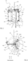
Figure 1 is a perspective view of a vertical axis wind turbine according to a preferred embodiment of the present invention; -
Figure 2 is a front view of the wind turbine ofFigure 1 , in a first operating condition; -
Figure 3 is a plan view of the wind turbine ofFigure 2 ; -
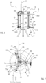
Figure 4 is a front view of the wind turbine ofFigure 1 , in a second operating condition; -
Figure 5 is a plan view of the wind turbine ofFigure 4 ; -
Figure 6 is a front view of the wind turbine ofFigure 1 , in a third operating condition; -
Figure 7 is a plan view of the wind turbine ofFigure 6 ; -
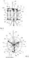
Figure 8 is a front view of the wind turbine ofFigure 1 , in a fourth operating condition; -
Figure 9 is a plan view of the wind turbine ofFigure 8 ; -
Figure 10 is a front view, similar to that ofFigure 2 , with the directional deflector angled according to a different wind flow direction; and -
Figure 11 is a plan view of the wind turbine ofFigure 10 . - With reference to
Figure 1 , it illustrates a vertical axis wind turbine according to a preferred embodiment of the present invention. - The turbine, indicated in general by the
reference number 10, comprises aground supporting base 1, comprising asupport surface 11 and a plurality offeet 12, and arotating shaft 2, which extends from thesupport surface 11 of thebase 1, centrally to it. - The
base 1 sustains asupport frame 3 for a plurality of blades, preferably threeblades shaft 2, with respect to thebase 1, around a rotation axis X1 shown inFigure 2 . - In particular, the
blade support frame 3 comprises alower rod structure 31 and anupper rod structure 32, equal to each other. Thelower rod structure 31 is mounted on theshaft 2 near thebase 1 and theupper rod structure 32 is mounted at a free end of theshaft 2, with homologous parts of thelower rod structure 31 andupper rod structure 32 facing one another. - The
lower rod structure 31 comprises ahub 311, which is keyed onto theshaft 2 and from whichrods 312 extend, preferably connected two by two by respective reinforcingrods 313. In the embodiment illustrated, thelower rod structure 31 comprises threerods 312, which extend from thehub 311 and are arranged substantially at 120° from one another, and three reinforcingrods 313. - Analogously to the
lower rod structure 31, theupper rod structure 32 comprises ahub 321, which is keyed onto theshaft 2 and from whichrods 322 extend, preferably connected two by two by respective reinforcingrods 323. In the embodiment illustrated, theupper rod structure 32 comprises threerods 322, which extend from thehub 321 and are arranged substantially at 120° from one another, and three reinforcingrods 323. -
Respective blades rods lower rod frame 31 and theupper rod frame 32. - Each
blade blade 41, radially internal with reference to theshaft 2, and a second half-blade 42, radially external with reference to theshaft 2, juxtaposed between each other. As will be described in detail below, eachblade blade support frame 3 between a maximum opening condition, in which the respective half-blades - Each first half-
blade 41 is fixed, at a lateral surface opposite that of juxtaposition with the second half-blade 42, namely a lateral surface radially nearer theshaft 2, to a fixedrod 43, which extends between thelower rod structure 31 and theupper rod structure 32 of theblade support frame 3, parallel to theshaft 2 of theturbine 10. - More specifically, each fixed
rod 43 has a lower end rotatably mounted, for example by means of roller bearings, on thelower rod structure 31 of theblade support frame 3 at the area of intersection between arespective rod 312 and the reinforcingrods 313 connected to it, and an upper end rotatably mounted, for example by means of roller bearings, on theupper rod structure 32 of theblade support frame 3 at the area of intersection between arespective rod 322 and the second reinforcingrods 323 connected to it. - Each second half-
blade 42 is fixed, at a lateral surface opposite that of juxtaposition with the first half-blade 41, namely a lateral surface radially farther from theshaft 2, to amobile rod 44, which extends between the frame parallel to theshaft 2 of theturbine 10. - More specifically, each
mobile rod 44 has a lower end provided with acarriage 45 sliding in aguide 47 obtained in therespective rod 312 of thelower rod structure 31 of theblade support frame 3, between the free end of therod 312 and the area of intersection of therod 312 with the reinforcingrods 313. - Furthermore, each
mobile rod 44 carries afurther carriage 46 sliding in aguide 48 formed in therespective rod 322 of theupper rod structure 32 of theblade support frame 3, between the free end of therod 322 and the area of intersection of therod 322 with the reinforcingrods 323. Theturbine 10 further comprises ablade control frame 5, which is mounted above theblade support frame 3, offset with respect to it. - In particular, the
blade control frame 5 comprises acontrol element 51, mounted on theshaft 2 of theturbine 10 immediately above theupper rod structure 32 of theblade support frame 3. From thecontrol element 51, in a position eccentric to theshaft 3, apin 52 extends, which supports a plurality of connectingrods 53, one for eachblade turbine 10, the connectingrods 53 being rotatable around an axis X2 of thepin 52, shown inFigure 2 . At a free end of each connectingrod 53, an upper end of themobile rod 44 of therespective blade - From the pin 52 a
directional deflector 54 further extends, which is connected to thepin 52 by means ofarms 55. - As will be described in detail below, the
directional deflector 54 is configured to angle according to the wind flow direction and fixes the reciprocal position between the axis X1 of theshaft 2 of theturbine 10, corresponding to the rotation axis of theblade support frame 3, and the axis X2 of thepin 52, corresponding to the rotation axis of theblade control frame 5. - With reference to
Figures 2 to 9 , the operation of the verticalaxis wind turbine 10, described above with reference toFigure 1 , is now described. - It is assumed, by way of example, that the wind blows in the direction indicated by the arrows in
Figures 3 ,5 ,7 and9 . In this case, thedirectional deflector 54 angles toward the direction of the wind flow and thereby fixes, in an absolute reference system corresponding to the plane of the page, the position of thepin 52 of theblade control frame 5 with respect to the position of theshaft 2 of theturbine 10. Said position of thepin 52 with respect to theshaft 2 is such that, during rotation of theturbine 10, theblade control frame 5 is always in the position of maximum efficiency, namely with the blade exposed in the direction of the wind flow in the maximum opening position, so as to receive maximum thrust, and the other blades are in the intermediate opening or maximum closing position, so as to oppose minimum resistance to the wind flow. It follows that the torsional moment is always greater than the resisting moment, with consequent increase in the efficiency of theturbine 10. - As can be seen in
Figures 3 ,5 ,7 and9 , the terminal or radially outermost ends of therods lower rod structure 31 and of theupper rod structure 32 of theblade support frame 3 rotate following an external circular trajectory T, with centre on the axis X1 of theshaft 2; the fixedrods 43 of theblades blade support frame 3, rotate following an internal circular trajectory TF concentric to the external circular trajectory T. - The
mobile rods 44 of theblades rod 53 of theblade control frame 5, rotate following a circular trajectory TM with centre on the axis X2 of thepin 52 and interposed between the external circular trajectory T and the internal circular trajectory TF. Since thepin 52 is offset with respect to theshaft 2 of theturbine 10, the circular trajectory TM, according to which themobile rods 44 of theblades mobile rods 44 move along the circular trajectory TM, and therefore depending on the angular position of the connectingrods 53, thecursors mobile rod 44 slide in the respective guides 47, 48 so that themobile rod 44 moves nearer to/away from the respective fixedrod 43. - The movement of the
mobile rod 44 nearer to the fixedrod 43 causes the half-blades blade mobile rod 44 away from the fixedrod 43 causes the half-blades blade - In a first operating condition of the
turbine 10, shown inFigures 2 and 3 , themobile rod 44 of theblade 4a, which is the blade exposed to the direction of the wind flow, is at the point of the circular trajectory TM nearest the external circular trajectory T, so that it is in a maximum opening position of the half-blades blade 4b is upstream of the point of the trajectory TM farthest from the external trajectory T, with respect to the rotation direction indicated by the arrow F inFigure 3 , with the respectivemobile rod 44 approaching the fixedrod 43 and the half-blades blade 4c is positioned downstream of the point of the trajectory TM farthest from the external trajectory T, with respect to the rotation direction of theturbine 10 indicated by the arrow F, with the respectivemobile rod 44 moving away from the fixedrod 43 and the half-blades - In a second operating condition of the
turbine 10, shown inFigures 4 and 5 , theblade 4a is upstream of the point of the trajectory TM farthest from the external trajectory T, with respect to the rotation direction indicated by the arrow F inFigure 3 , with the respectivemobile rod 44 approaching the fixedrod 43 and the half-blades blade 4b is positioned downstream of the point of the trajectory TM farthest from the external trajectory T, with respect to the rotation direction indicated by the arrow F, with the respectivemobile rod 44 moving away from the fixedrod 43 and the half-blades blade 4c is downstream of the point of the trajectory TM nearest the external trajectory T, with respect to the rotation direction indicated by the arrow F, with the respectivemobile rod 44 approaching the fixedrod 43 and the half-blades - In a third operating condition of the
turbine 10, shown inFigures 6 and 7 , themobile rod 44 of theblade 4a is at the point of the circular trajectory TM farthest from the external circular trajectory T, so that it is in the maximum closing position of the half-blades blade 4b is upstream of the point of the trajectory TM nearest the external trajectory T, with respect to the rotation direction indicated by the arrow F inFigure 7 , with the respectivemobile rod 44 moving away from the fixedrod 43 and the half-blades blade 4c is positioned downstream of the point of the trajectory TM nearest the external trajectory T, with respect to the rotation direction of theturbine 10 indicated by the arrow F, with the respectivemobile rod 44 approaching the fixedrod 43 and the half-blades - In a fourth operating condition of the
turbine 10, shown inFigures 8 and 9 , theblade 4a is upstream of the point of the trajectory TM nearest the external trajectory T, with respect to the rotation direction indicated by the arrow F inFigure 9 , with the respectivemobile rod 44 moving away from the fixedrod 43 and the half-blades blade 4b is positioned downstream of the point of the trajectory TM nearest the external trajectory T, with respect to the rotation direction indicated by the arrow F, with the respectivemobile rod 44 approaching the fixedrod 43 and the half-blades blade 4c is upstream of the point of the trajectory TM farthest from the external trajectory T, with respect to the rotation direction indicated by the arrow F, with the respectivemobile rod 44 approaching the fixedrod 43 and the half-blades - In the case of variation in the wind flow, the
turbine 10 according to the invention is able to self-align according to the new wind direction, so that theblade control frame 5 is always in the position of maximum efficiency. - It is assumed, by way of example, that the wind flow direction varies with respect to the one shown in
Figures 2 to 9 . This condition is shown inFigures 10 and 11 . - As the wind flow direction varies, the
directional deflector 54 modifies its position and, consequently, fixes a new position of thepin 52 of theblade control frame 5 with respect to the position of theshaft 2 of theturbine 10. In fact, comparingFigure 11 for example withFigure 3 , it can be seen that thepin 52 of theblade control frame 5, instead of being aligned horizontally with theshaft 2 of theturbine 10, is higher than theshaft 2. - In this way, the
blade control frame 5 is again in the position of maximum efficiency, namely with the blade exposed in the direction of the wind flow in the maximum opening position, so as to receive maximum thrust, and the other blades in the intermediate opening or maximum closing position, so as to oppose minimum resistance to the wind flow. It follows that, also in this different position of thedirectional deflector 54, and of theblade control frame 5, the torsional moment is greater than the resisting moment, with consequent increase in the efficiency of theturbine 10. - From the above description the characteristics of the vertical axis wind turbine of the present invention are evident, and likewise the relative advantages thereof.
- The scope of protection is defined by the appended claims.
Claims (10)
- Vertical axis wind turbine (10) comprising a support base (1), a shaft (2) extending centrally from the support base (1), a support frame (3) for a plurality of blades (4a, 4b, 4c), mounted on the base (1) rotatable with the shaft (2), and a control frame (5) for the plurality of blades (4a, 4b, 4c), mounted on the shaft (2), above the blade support frame (3);wherein each blade of the plurality of blades (4a, 4b, 4c) comprises a first half-blade (41) and a second half-blade (42) supported by the blade support frame (3);characterized in that the blade control frame (5) comprises a control element (51) mounted rotatably on the shaft (2), a pin (52), extending from the control element (51) in an eccentric position with respect to the shaft (2), a plurality of connecting rods (53), one for each blade (4a, 4b, 4c), rotatably supported by the pin (52) and a directional deflector (54) extending from the pin (52) and rotatable integrally with it;and in that each blade (4a, 4b, 4c) comprises a fixed rod (43) associated with the blade support frame (3) and a mobile rod (44) having an end sliding on the blade support frame (3) and another end associated with a respective connecting rod (53) of the blade control frame (5);wherein, during the rotation of the turbine (10), the directional deflector (54) angles toward the direction of the wind flow, thereby fixing an angular position of the pin (52) with respect to the shaft (2) and the mobile rod (44) of each blade (4a, 4b, 4c) rotates following a trajectory (TM), eccentric with respect to a trajectory (TF) of the fixed rod (43), sliding on the blade support frame (3) and thus causing the opening and closing of the blades (4a, 4b, 4c).
- Turbine (10) according to claim 1, wherein the first half-blade (41) and the secondo half-blade (42) of each blade (4a, 4b, 4c) are juxtaposed between each other, the first half-blade (41) being radially internal and the second half-blade (42) being radially external.
- Turbine (10) according to claim 1 or 2, wherein the blade support frame (3) comprises a lower rod structure (31) and an upper rod structure (32) identical to each other, wherein the lower rod structure (31) is mounted on the shaft (2) near the base (1) and the upper rod structure (32) is mounted at a free end of the shaft (2), with homologous parts facing each other.
- Turbine (10) according to claim 3, wherein the lower rod structure (31) comprises a hub (311), which is keyed onto the shaft (2) and from which rods (312) extend, connected to one another by reinforcing rods (313), and the upper rod structure (32) comprises a hub (321), which is keyed onto the shaft (2) and from which rods (322) extend, connected to one another by reinforcing rods (323).
- Turbine (10) according to claim 3 or 4, wherein the fixed rod (43) is fixed to the first half-blade (41) of each blade (4a, 4b, 4c) at a lateral surface opposite to that of juxtaposition with the second half-blade (42), while the mobile rod (44) is fixed to the second half-blade (42) at a lateral surface opposite to that of juxtaposition with the first half-blade (41).
- Turbine (10) according to any one of claims 3 to 5, wherein the fixed rod (43) of each blade (4a, 4b, 4c) has a lower end rotatably mounted on the lower rod structure (31) of the blade support frame (3) and an upper end rotatably mounted on the upper rod structure (32) of the blade support frame (3).
- Turbine (10) according to any one of claims 3 to 6, wherein the mobile rod (44) of each blade (4a, 4b, 4c) has a lower end provided with a carriage (45) sliding into a guide ( 47) formed in the lower rod structure (31) of the blade support frame (3), the other end rotatably mounted at an end of the respective connecting rod (53) of the blade control frame (5) and carries a further carriage (46) sliding into a guide (48) formed in the upper rod structure (32) of the blade support frame (3).
- Turbine (10) according to any one of the preceding claims, wherein the plurality of blades comprises three blades (4a, 4b, 4c) arranged at substantially 120° from one another.
- Turbine (10) according to any one of the preceding claims, wherein the trajectory (TF) followed by the fixed rods (43) of the blades (4a, 4b, 4c) is concentric to a trajectory (T) followed by radially outermost portions of the lower rod structure (31) and the upper rod structure (32) of the blade support frame (3).
- Turbine (10) according to claim 9, wherein the trajectories (T, TF, TM) are circular.
Applications Claiming Priority (1)
| Application Number | Priority Date | Filing Date | Title |
|---|---|---|---|
| IT102021000019625A IT202100019625A1 (en) | 2021-07-23 | 2021-07-23 | VERTICAL AXIS WIND TURBINE |
Publications (3)
| Publication Number | Publication Date |
|---|---|
| EP4123164A1 EP4123164A1 (en) | 2023-01-25 |
| EP4123164C0 EP4123164C0 (en) | 2024-02-14 |
| EP4123164B1 true EP4123164B1 (en) | 2024-02-14 |
Family
ID=78212491
Family Applications (1)
| Application Number | Title | Priority Date | Filing Date |
|---|---|---|---|
| EP22186179.2A Active EP4123164B1 (en) | 2021-07-23 | 2022-07-21 | Vertical axis wind turbine |
Country Status (2)
| Country | Link |
|---|---|
| EP (1) | EP4123164B1 (en) |
| IT (1) | IT202100019625A1 (en) |
Family Cites Families (3)
| Publication number | Priority date | Publication date | Assignee | Title |
|---|---|---|---|---|
| KR101633136B1 (en) * | 2011-05-26 | 2016-06-23 | 현대중공업 주식회사 | Vertical-axis type wind turbine with variable blades |
| DE102012019268B4 (en) * | 2012-09-24 | 2018-10-31 | Leonid Uschpol | Wind power plant |
| PL241530B1 (en) * | 2019-02-21 | 2022-10-17 | Politechnika Lodzka | Wind turbine with a vertical rotation axis and variable blade geometry |
-
2021
- 2021-07-23 IT IT102021000019625A patent/IT202100019625A1/en unknown
-
2022
- 2022-07-21 EP EP22186179.2A patent/EP4123164B1/en active Active
Also Published As
| Publication number | Publication date |
|---|---|
| EP4123164A1 (en) | 2023-01-25 |
| EP4123164C0 (en) | 2024-02-14 |
| IT202100019625A1 (en) | 2023-01-23 |
Similar Documents
| Publication | Publication Date | Title |
|---|---|---|
| US7802967B2 (en) | Vertical axis self-breaking wind turbine | |
| US20110006526A1 (en) | Pitch control arrangement for wind turbine | |
| EP1888917B1 (en) | Vertical axis wind turbine having an overspeeding regulator controlling multiple aerodynamic elements | |
| US10612515B2 (en) | Vertical axis wind turbine | |
| US8974184B2 (en) | Turbomachinery having self-articulating blades, shutter valve, partial-admission shutters, and/or variable pitch inlet nozzles | |
| US20140356163A1 (en) | Turbomachine | |
| CN202991352U (en) | Lift-drag combined vertical-axis wind turbine with automatic blade adjustment | |
| EP3564525B1 (en) | Vertical shaft wind power generator driving device for self-adaptive variable-propeller, and wind power generator | |
| US20140077505A1 (en) | Wind Turbine Apparatus | |
| WO2015166477A1 (en) | A vertical axis wind turbine with self-orientating blades | |
| US20200132044A1 (en) | Wind turbine | |
| EP2616675A2 (en) | Vertical axis wind turbine | |
| US20140064918A1 (en) | Device and system for harvesting the energy of a fluid stream | |
| KR20120061264A (en) | Vertical axis wind turbine having cascaded mutiblade | |
| WO2017180829A1 (en) | Improvements related to savonius wind turbines | |
| CN115066551B (en) | Drag and lift based wind turbine system with adjustable blades | |
| WO2017110298A1 (en) | Windmill system and wind farm | |
| US20170107972A1 (en) | Vertical wind turbine | |
| EP4123164A1 (en) | Vertical axis wind turbine | |
| GB2474961A (en) | Turbine with upwind horizontal axis rotor and passive yaw adjustment | |
| EP2617991A1 (en) | Vertical axis wind turbine | |
| WO2013109133A1 (en) | A wind turbine | |
| KR101810872B1 (en) | Apparatus for generating by wind power | |
| KR101630111B1 (en) | Blade angle control system of wind power generator | |
| DK202200086U3 (en) | Counter-rotating wind turbine and wind power plant comprising a counter-rotating wind turbine |
Legal Events
| Date | Code | Title | Description |
|---|---|---|---|
| PUAI | Public reference made under article 153(3) epc to a published international application that has entered the european phase |
Free format text: ORIGINAL CODE: 0009012 |
|
| STAA | Information on the status of an ep patent application or granted ep patent |
Free format text: STATUS: THE APPLICATION HAS BEEN PUBLISHED |
|
| AK | Designated contracting states |
Kind code of ref document: A1 Designated state(s): AL AT BE BG CH CY CZ DE DK EE ES FI FR GB GR HR HU IE IS IT LI LT LU LV MC MK MT NL NO PL PT RO RS SE SI SK SM TR |
|
| STAA | Information on the status of an ep patent application or granted ep patent |
Free format text: STATUS: REQUEST FOR EXAMINATION WAS MADE |
|
| 17P | Request for examination filed |
Effective date: 20230718 |
|
| RBV | Designated contracting states (corrected) |
Designated state(s): AL AT BE BG CH CY CZ DE DK EE ES FI FR GB GR HR HU IE IS IT LI LT LU LV MC MK MT NL NO PL PT RO RS SE SI SK SM TR |
|
| GRAP | Despatch of communication of intention to grant a patent |
Free format text: ORIGINAL CODE: EPIDOSNIGR1 |
|
| STAA | Information on the status of an ep patent application or granted ep patent |
Free format text: STATUS: GRANT OF PATENT IS INTENDED |
|
| INTG | Intention to grant announced |
Effective date: 20230907 |
|
| GRAS | Grant fee paid |
Free format text: ORIGINAL CODE: EPIDOSNIGR3 |
|
| GRAA | (expected) grant |
Free format text: ORIGINAL CODE: 0009210 |
|
| STAA | Information on the status of an ep patent application or granted ep patent |
Free format text: STATUS: THE PATENT HAS BEEN GRANTED |
|
| AK | Designated contracting states |
Kind code of ref document: B1 Designated state(s): AL AT BE BG CH CY CZ DE DK EE ES FI FR GB GR HR HU IE IS IT LI LT LU LV MC MK MT NL NO PL PT RO RS SE SI SK SM TR |
|
| REG | Reference to a national code |
Ref country code: GB Ref legal event code: FG4D |
|
| REG | Reference to a national code |
Ref country code: CH Ref legal event code: EP |
|
| REG | Reference to a national code |
Ref country code: DE Ref legal event code: R096 Ref document number: 602022001942 Country of ref document: DE |
|
| REG | Reference to a national code |
Ref country code: IE Ref legal event code: FG4D |
|
| U01 | Request for unitary effect filed |
Effective date: 20240307 |
|
| U07 | Unitary effect registered |
Designated state(s): AT BE BG DE DK EE FI FR IT LT LU LV MT NL PT SE SI Effective date: 20240326 |
|
| PG25 | Lapsed in a contracting state [announced via postgrant information from national office to epo] |
Ref country code: IS Free format text: LAPSE BECAUSE OF FAILURE TO SUBMIT A TRANSLATION OF THE DESCRIPTION OR TO PAY THE FEE WITHIN THE PRESCRIBED TIME-LIMIT Effective date: 20240614 |
|
| PG25 | Lapsed in a contracting state [announced via postgrant information from national office to epo] |
Ref country code: GR Free format text: LAPSE BECAUSE OF FAILURE TO SUBMIT A TRANSLATION OF THE DESCRIPTION OR TO PAY THE FEE WITHIN THE PRESCRIBED TIME-LIMIT Effective date: 20240515 |
|
| PG25 | Lapsed in a contracting state [announced via postgrant information from national office to epo] |
Ref country code: RS Free format text: LAPSE BECAUSE OF FAILURE TO SUBMIT A TRANSLATION OF THE DESCRIPTION OR TO PAY THE FEE WITHIN THE PRESCRIBED TIME-LIMIT Effective date: 20240514 Ref country code: HR Free format text: LAPSE BECAUSE OF FAILURE TO SUBMIT A TRANSLATION OF THE DESCRIPTION OR TO PAY THE FEE WITHIN THE PRESCRIBED TIME-LIMIT Effective date: 20240214 |
|
| PG25 | Lapsed in a contracting state [announced via postgrant information from national office to epo] |
Ref country code: ES Free format text: LAPSE BECAUSE OF FAILURE TO SUBMIT A TRANSLATION OF THE DESCRIPTION OR TO PAY THE FEE WITHIN THE PRESCRIBED TIME-LIMIT Effective date: 20240214 |
|
| PG25 | Lapsed in a contracting state [announced via postgrant information from national office to epo] |
Ref country code: RS Free format text: LAPSE BECAUSE OF FAILURE TO SUBMIT A TRANSLATION OF THE DESCRIPTION OR TO PAY THE FEE WITHIN THE PRESCRIBED TIME-LIMIT Effective date: 20240514 Ref country code: NO Free format text: LAPSE BECAUSE OF FAILURE TO SUBMIT A TRANSLATION OF THE DESCRIPTION OR TO PAY THE FEE WITHIN THE PRESCRIBED TIME-LIMIT Effective date: 20240514 Ref country code: IS Free format text: LAPSE BECAUSE OF FAILURE TO SUBMIT A TRANSLATION OF THE DESCRIPTION OR TO PAY THE FEE WITHIN THE PRESCRIBED TIME-LIMIT Effective date: 20240614 Ref country code: HR Free format text: LAPSE BECAUSE OF FAILURE TO SUBMIT A TRANSLATION OF THE DESCRIPTION OR TO PAY THE FEE WITHIN THE PRESCRIBED TIME-LIMIT Effective date: 20240214 Ref country code: GR Free format text: LAPSE BECAUSE OF FAILURE TO SUBMIT A TRANSLATION OF THE DESCRIPTION OR TO PAY THE FEE WITHIN THE PRESCRIBED TIME-LIMIT Effective date: 20240515 Ref country code: ES Free format text: LAPSE BECAUSE OF FAILURE TO SUBMIT A TRANSLATION OF THE DESCRIPTION OR TO PAY THE FEE WITHIN THE PRESCRIBED TIME-LIMIT Effective date: 20240214 |
|
| PG25 | Lapsed in a contracting state [announced via postgrant information from national office to epo] |
Ref country code: PL Free format text: LAPSE BECAUSE OF FAILURE TO SUBMIT A TRANSLATION OF THE DESCRIPTION OR TO PAY THE FEE WITHIN THE PRESCRIBED TIME-LIMIT Effective date: 20240214 |
|
| U20 | Renewal fee for the european patent with unitary effect paid |
Year of fee payment: 3 Effective date: 20240710 |
|
| PG25 | Lapsed in a contracting state [announced via postgrant information from national office to epo] |
Ref country code: PL Free format text: LAPSE BECAUSE OF FAILURE TO SUBMIT A TRANSLATION OF THE DESCRIPTION OR TO PAY THE FEE WITHIN THE PRESCRIBED TIME-LIMIT Effective date: 20240214 |
|
| PG25 | Lapsed in a contracting state [announced via postgrant information from national office to epo] |
Ref country code: SM Free format text: LAPSE BECAUSE OF FAILURE TO SUBMIT A TRANSLATION OF THE DESCRIPTION OR TO PAY THE FEE WITHIN THE PRESCRIBED TIME-LIMIT Effective date: 20240214 |
|
| PG25 | Lapsed in a contracting state [announced via postgrant information from national office to epo] |
Ref country code: CZ Free format text: LAPSE BECAUSE OF FAILURE TO SUBMIT A TRANSLATION OF THE DESCRIPTION OR TO PAY THE FEE WITHIN THE PRESCRIBED TIME-LIMIT Effective date: 20240214 |
|
| PG25 | Lapsed in a contracting state [announced via postgrant information from national office to epo] |
Ref country code: SK Free format text: LAPSE BECAUSE OF FAILURE TO SUBMIT A TRANSLATION OF THE DESCRIPTION OR TO PAY THE FEE WITHIN THE PRESCRIBED TIME-LIMIT Effective date: 20240214 |
|
| PG25 | Lapsed in a contracting state [announced via postgrant information from national office to epo] |
Ref country code: SM Free format text: LAPSE BECAUSE OF FAILURE TO SUBMIT A TRANSLATION OF THE DESCRIPTION OR TO PAY THE FEE WITHIN THE PRESCRIBED TIME-LIMIT Effective date: 20240214 Ref country code: SK Free format text: LAPSE BECAUSE OF FAILURE TO SUBMIT A TRANSLATION OF THE DESCRIPTION OR TO PAY THE FEE WITHIN THE PRESCRIBED TIME-LIMIT Effective date: 20240214 Ref country code: RO Free format text: LAPSE BECAUSE OF FAILURE TO SUBMIT A TRANSLATION OF THE DESCRIPTION OR TO PAY THE FEE WITHIN THE PRESCRIBED TIME-LIMIT Effective date: 20240214 Ref country code: CZ Free format text: LAPSE BECAUSE OF FAILURE TO SUBMIT A TRANSLATION OF THE DESCRIPTION OR TO PAY THE FEE WITHIN THE PRESCRIBED TIME-LIMIT Effective date: 20240214 |
|
| REG | Reference to a national code |
Ref country code: DE Ref legal event code: R097 Ref document number: 602022001942 Country of ref document: DE |
|
| PLBE | No opposition filed within time limit |
Free format text: ORIGINAL CODE: 0009261 |
|
| STAA | Information on the status of an ep patent application or granted ep patent |
Free format text: STATUS: NO OPPOSITION FILED WITHIN TIME LIMIT |
|
| 26N | No opposition filed |
Effective date: 20241115 |
|
| PG25 | Lapsed in a contracting state [announced via postgrant information from national office to epo] |
Ref country code: MC Free format text: LAPSE BECAUSE OF FAILURE TO SUBMIT A TRANSLATION OF THE DESCRIPTION OR TO PAY THE FEE WITHIN THE PRESCRIBED TIME-LIMIT Effective date: 20240214 |
|
| PG25 | Lapsed in a contracting state [announced via postgrant information from national office to epo] |
Ref country code: IE Free format text: LAPSE BECAUSE OF NON-PAYMENT OF DUE FEES Effective date: 20240721 |
|
| U20 | Renewal fee for the european patent with unitary effect paid |
Year of fee payment: 4 Effective date: 20250714 |
|
| PG25 | Lapsed in a contracting state [announced via postgrant information from national office to epo] |
Ref country code: CY Free format text: LAPSE BECAUSE OF FAILURE TO SUBMIT A TRANSLATION OF THE DESCRIPTION OR TO PAY THE FEE WITHIN THE PRESCRIBED TIME-LIMIT; INVALID AB INITIO Effective date: 20220721 |
|
| REG | Reference to a national code |
Ref country code: CH Ref legal event code: H13 Free format text: ST27 STATUS EVENT CODE: U-0-0-H10-H13 (AS PROVIDED BY THE NATIONAL OFFICE) Effective date: 20260224 |
|
| PG25 | Lapsed in a contracting state [announced via postgrant information from national office to epo] |
Ref country code: HU Free format text: LAPSE BECAUSE OF FAILURE TO SUBMIT A TRANSLATION OF THE DESCRIPTION OR TO PAY THE FEE WITHIN THE PRESCRIBED TIME-LIMIT; INVALID AB INITIO Effective date: 20220721 |
|
| PG25 | Lapsed in a contracting state [announced via postgrant information from national office to epo] |
Ref country code: CH Free format text: LAPSE BECAUSE OF NON-PAYMENT OF DUE FEES Effective date: 20250731 |