EP4122776A1 - Electronic control device - Google Patents
Electronic control device Download PDFInfo
- Publication number
- EP4122776A1 EP4122776A1 EP21771716.4A EP21771716A EP4122776A1 EP 4122776 A1 EP4122776 A1 EP 4122776A1 EP 21771716 A EP21771716 A EP 21771716A EP 4122776 A1 EP4122776 A1 EP 4122776A1
- Authority
- EP
- European Patent Office
- Prior art keywords
- heat
- case
- electronic control
- control device
- component
- Prior art date
- Legal status (The legal status is an assumption and is not a legal conclusion. Google has not performed a legal analysis and makes no representation as to the accuracy of the status listed.)
- Pending
Links
Images


Classifications
-
- H—ELECTRICITY
- H05—ELECTRIC TECHNIQUES NOT OTHERWISE PROVIDED FOR
- H05K—PRINTED CIRCUITS; CASINGS OR CONSTRUCTIONAL DETAILS OF ELECTRIC APPARATUS; MANUFACTURE OF ASSEMBLAGES OF ELECTRICAL COMPONENTS
- H05K5/00—Casings, cabinets or drawers for electric apparatus
- H05K5/0026—Casings, cabinets or drawers for electric apparatus provided with connectors and printed circuit boards [PCB], e.g. automotive electronic control units
- H05K5/0047—Casings, cabinets or drawers for electric apparatus provided with connectors and printed circuit boards [PCB], e.g. automotive electronic control units having a two-part housing enclosing a PCB
- H05K5/0056—Casings, cabinets or drawers for electric apparatus provided with connectors and printed circuit boards [PCB], e.g. automotive electronic control units having a two-part housing enclosing a PCB characterized by features for protecting electronic components against vibration and moisture, e.g. potting, holders for relatively large capacitors
-
- H—ELECTRICITY
- H05—ELECTRIC TECHNIQUES NOT OTHERWISE PROVIDED FOR
- H05K—PRINTED CIRCUITS; CASINGS OR CONSTRUCTIONAL DETAILS OF ELECTRIC APPARATUS; MANUFACTURE OF ASSEMBLAGES OF ELECTRICAL COMPONENTS
- H05K5/00—Casings, cabinets or drawers for electric apparatus
- H05K5/0026—Casings, cabinets or drawers for electric apparatus provided with connectors and printed circuit boards [PCB], e.g. automotive electronic control units
- H05K5/0047—Casings, cabinets or drawers for electric apparatus provided with connectors and printed circuit boards [PCB], e.g. automotive electronic control units having a two-part housing enclosing a PCB
-
- H—ELECTRICITY
- H05—ELECTRIC TECHNIQUES NOT OTHERWISE PROVIDED FOR
- H05K—PRINTED CIRCUITS; CASINGS OR CONSTRUCTIONAL DETAILS OF ELECTRIC APPARATUS; MANUFACTURE OF ASSEMBLAGES OF ELECTRICAL COMPONENTS
- H05K5/00—Casings, cabinets or drawers for electric apparatus
- H05K5/04—Metal casings
-
- H—ELECTRICITY
- H05—ELECTRIC TECHNIQUES NOT OTHERWISE PROVIDED FOR
- H05K—PRINTED CIRCUITS; CASINGS OR CONSTRUCTIONAL DETAILS OF ELECTRIC APPARATUS; MANUFACTURE OF ASSEMBLAGES OF ELECTRICAL COMPONENTS
- H05K7/00—Constructional details common to different types of electric apparatus
- H05K7/20—Modifications to facilitate cooling, ventilating, or heating
- H05K7/2039—Modifications to facilitate cooling, ventilating, or heating characterised by the heat transfer by conduction from the heat generating element to a dissipating body
-
- H—ELECTRICITY
- H05—ELECTRIC TECHNIQUES NOT OTHERWISE PROVIDED FOR
- H05K—PRINTED CIRCUITS; CASINGS OR CONSTRUCTIONAL DETAILS OF ELECTRIC APPARATUS; MANUFACTURE OF ASSEMBLAGES OF ELECTRICAL COMPONENTS
- H05K7/00—Constructional details common to different types of electric apparatus
- H05K7/20—Modifications to facilitate cooling, ventilating, or heating
- H05K7/2039—Modifications to facilitate cooling, ventilating, or heating characterised by the heat transfer by conduction from the heat generating element to a dissipating body
- H05K7/20436—Inner thermal coupling elements in heat dissipating housings, e.g. protrusions or depressions integrally formed in the housing
-
- H—ELECTRICITY
- H05—ELECTRIC TECHNIQUES NOT OTHERWISE PROVIDED FOR
- H05K—PRINTED CIRCUITS; CASINGS OR CONSTRUCTIONAL DETAILS OF ELECTRIC APPARATUS; MANUFACTURE OF ASSEMBLAGES OF ELECTRICAL COMPONENTS
- H05K7/00—Constructional details common to different types of electric apparatus
- H05K7/20—Modifications to facilitate cooling, ventilating, or heating
- H05K7/20845—Modifications to facilitate cooling, ventilating, or heating for automotive electronic casings
- H05K7/20854—Heat transfer by conduction from internal heat source to heat radiating structure
-
- H—ELECTRICITY
- H05—ELECTRIC TECHNIQUES NOT OTHERWISE PROVIDED FOR
- H05K—PRINTED CIRCUITS; CASINGS OR CONSTRUCTIONAL DETAILS OF ELECTRIC APPARATUS; MANUFACTURE OF ASSEMBLAGES OF ELECTRICAL COMPONENTS
- H05K5/00—Casings, cabinets or drawers for electric apparatus
- H05K5/0026—Casings, cabinets or drawers for electric apparatus provided with connectors and printed circuit boards [PCB], e.g. automotive electronic control units
- H05K5/0047—Casings, cabinets or drawers for electric apparatus provided with connectors and printed circuit boards [PCB], e.g. automotive electronic control units having a two-part housing enclosing a PCB
- H05K5/006—Casings, cabinets or drawers for electric apparatus provided with connectors and printed circuit boards [PCB], e.g. automotive electronic control units having a two-part housing enclosing a PCB characterized by features for holding the PCB within the housing
Definitions
- the present invention relates to an electronic control device including a circuit board on which a heat-generating component and a heat-degradable component are mounted.
- an in-vehicle electronic control device includes a circuit board.
- a circuit board of this type is required to have high heat resistance and vibration resistance.
- a heat-generating component that generates heat during operation and a component that requires vibration countermeasures in consideration of vibration of a vehicle are mounted in mixed relation.
- the component that requires vibration countermeasures has a size mainly larger in a height direction. Accordingly, as one of means for improving the vibration resistance of the component that requires vibration countermeasures, it has been known to, e.g., support, with respect to the metallic housing, the component that requires vibration countermeasures at a position as distant as possible from a position at which the component that requires vibration countermeasures is connected by soldering to the circuit board.
- PTL 1 discloses a circuit board of an electronic device.
- a container case of the electronic device described in PTL 1 is internally filled with a heat-dissipating resin for heat dissipation.
- a leading end portion of a heat-generating component on the circuit board is buried in the heat-dissipating resin in the container case. Accordingly, heat generated from the heat-generating component is transmitted to the container case through the heat-dissipating resin to be diffused therein.
- a leading end portion of a low-heat-generating component described in PTL 1 is buried in the heat-dissipating resin in the container case via a protective cap made of an elastic member.
- the protective cap keeps the heat generated from the heat-generating component from being transmitted to the low-heat-generating component via the heat-dissipating resin.
- examples of the component that requires vibration countermeasures include a component that undergoes heat degradation such as, e.g., an electrolytic capacitor.
- a component that undergoes heat degradation such as, e.g., an electrolytic capacitor.
- the heat generated from the heat-generating component may be transmitted via the metallic housing to a component (such as, e.g., an electrolytic capacitor) that undergoes heat degradation among the components that require vibration countermeasures. This may undesirably accelerate the heat degradation of the component that undergoes heat degradation among the components that require vibration countermeasures.
- the present invention has been achieved in order to solve the problem described above, and an object thereof is to provide an electronic control device that can suppress heat degradation of a heat-degradable component that requires vibration countermeasures and also undergoes heat degradation, while improving vibration resistance of the heat-degradable component.
- an electronic control device including: a circuit board having a first surface on which a heat-generating component that generates heat during operation and a heat-degradable component that requires vibration countermeasures and also undergoes heat degradation are mounted; a first metallic case covering the first surface; a second case covering a second surface of the circuit board opposite to the first surface; a supporting member provided between the heat-degradable component and the first case to support the heat-degradable component; and a heat-dissipating member provided on at least either of the heat-generating component and the first case to transmit the heat generated from the heat-generating component to the first case, a heat conductivity of the heat-dissipating member being higher than a heat conductivity of the supporting member.
- the heat-degradable component that requires vibration countermeasures and also undergoes heat degradation is supported by the supporting member provided between the heat-degradable component and the first case.
- the heat generated from the heat-generating component is transmitted to the metallic first case via the heat-dissipating member provided on at least either of the heat-generating component and the first case to be diffused therein. It is to be noted herein that the heat conductivity of the heat-dissipating member is higher than the heat conductivity of the supporting member.
- the supporting member can suppress the heat transmitted to the first case from being transmitted to the heat-degradable component and also support the heat-degradable component. This allows the electronic control device according to the present invention to suppress the heat degradation of the heat-degradable component that requires vibration countermeasures and also undergoes heat degradation, while improving vibration resistance of the heat-degradable component.
- the supporting member is disposed between the heat-degradable component and the first case.
- the supporting member is disposed between the heat-degradable component and the first case. Therefore, the supporting member can more reliably suppress the heat diffused into the first case from being transmitted to the heat-degradable component that requires vibration countermeasures and also undergoes heat degradation and more reliably suppress the heat degradation of the heat-degradable component, while securely supporting the heat-degradable component by using the first case.
- the heat-dissipating member is provided to be interposed between the heat-generating component and the first case.
- the heat-dissipating member is provided to be interposed between the heat-generating component and the first case. Therefore, the heat-dissipating member can allow the heat generated from the heat-generating component during operation to be more reliably transmitted to the first case and more reliably dissipate the heat from the heat-generating component.
- the electronic control device further includes: a sealing agent disposed between the first case and the second case to bond the first case and the second case together and liquid-tightly seal the circuit board between the first case and the second case, wherein a material of the sealing agent is the same as a material of the supporting member.
- the material of the sealing agent liquid-tightly sealing the circuit board between the first case and the second case is the same as the material of the supporting member. Therefore, it is possible to reduce the types of the members to unify the types of the members, and simplify a process of producing the electronic control device.
- the heat-generating component is a first heat-generating component
- the heat-dissipating member is a first heat-dissipating member
- the electronic control device further includes: a second heat-generating component mounted on the second surface to generate heat during operation; and a second heat-dissipating member additionally provided on the second heat-generating component to dissipate heat generated from the second heat-generating component.
- the heat generated from the second heat-generating component mounted on the second surface of the circuit board is transmitted to the circuit board and the first case via the second heat-dissipating member additionally provided on the second heat-generating component to be diffused therein or diffused by radiation via the second heat-dissipating member.
- the circuit board is used to control operation of an engine of a vehicle, and the first case is attached to at least either of the engine and a vehicle body in which the engine is mounted.
- the electronic control device When the electronic control device according to the present invention is attached to at least either of the engine of the vehicle and the vehicle body in which the engine is mounted, the electronic control device can suppress the heat degradation of the heat-degradable component that requires vibration countermeasures and also undergoes heat degradation, while improving the vibration resistance of the heat-degradable component. As a result, it is possible to improve durability and reliability of the in-vehicle electronic control device.
- the first case is attached using a fastening member to at least either of the engine and the vehicle body to have a surface thereof brought into contact with a surface of at least either of the engine and the vehicle body.
- the first case is attached using the fastening member to at least either of the engine and the vehicle body and has the surface thereof brought into contact with the surface of at least either of the engine and the vehicle body.
- an electronic control device that can suppress heat degradation of a heat-degradable component that requires vibration countermeasures and also undergoes heat degradation, while improving vibration resistance of the heat-degradable component.
- Fig. 1 is a perspective view illustrating an electronic control device according to an embodiment of the present invention.
- Fig. 2 is a perspective view illustrating an upper case of the electronic control device according to the present embodiment.
- Fig. 2 illustrates an inner surface (back surface) side of the upper case.
- An electronic control device 1 illustrated in Fig. 1 is used as, e.g., an in-vehicle electronic control device.
- the electronic control device 1 to be used for an in-vehicle application is an engine control unit (ECU), and generally controls an electrical auxiliary device to be used when, e.g., drive control, safety control, or the like for an engine is performed.
- ECU engine control unit
- the engine to which the electronic control device 1 is applied is, e.g., an internal combustion engine.
- An engine of this type is mounted in a vehicle such as, e.g., a construction machine, a farm machine, a lawn mower, or an automobile or the like.
- the engine is, e.g., a supercharged diesel engine with a turbo-charger.
- the engine is not limited thereto, and may also be a naturally aspired diesel engine, a supercharged gasoline engine with a turbo-charger, a naturally aspired gasoline engine, or a hybrid diesel engine or a hybrid gasoline engine using an electric motor in combination.
- the electronic control device 1 illustrated in Fig. 1 is attached to, e.g., a vehicle body of a vehicle or the engine.
- the electronic control device 1 is removably attached to a mounting object 200 such as the vehicle body or engine.
- a mounting object 200 such as the vehicle body or engine.
- the mounting object 200 include a member in an engine room of the vehicle body of the vehicle, a member in a cabin of a driver seat, the engine, and the like.
- bolt through holes 151 are provided.
- the bolts 201 illustrated in Fig. 1 are fitted into the mounting object 200 through the individual bolt through holes 151 to allow the electronic control device 1 to be removably attached to the mounting object 200.
- the bolts 201 in the present embodiment are an example of a "fastening member" in the present embodiment.
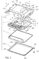
- Fig. 3 is an exploded perspective view illustrating an example of a configuration of the electronic control device according to the present embodiment.
- Fig. 4 is a cross-sectional view along a cut plane G-G line illustrated in Fig. 1 .
- the electronic control device 1 includes the upper case 2, a lower case 3, an electronic control substrate 4, and a sealing agent 5.
- the electronic control substrate 4 in the present embodiment is an example of a "circuit board" in the present invention.
- the upper case 2 in the present embodiment is an example of a "first case” in the present invention.
- the lower case 3 in the present embodiment is an example of a "second case” in the present invention.
- the upper case 2 and the lower case 3 use the sealing agent 5 to contain therein the electronic control substrate 4 in a liquid-tightly sealed or hermetically sealed state, and are fastened together using a plurality of bolts 221 illustrated in Fig. 3 .
- the upper case 2 and the lower case 3 are included in a metallic housing 10.
- the upper case 2 and the lower case 3 of the housing 10 ensure each of functions required of the in-vehicle electronic control device 1, such as heat dissipation, dust-proofness, water-proofness, vibration resistance, and heat resistance.
- the upper case 2 illustrated in Figs. 2 and 3 which is required to dissipate heat generated in the electronic control device 1, is a metallic housing having heat dissipation, and is molded by, e.g., aluminum die-casting.
- the upper case 2 has an uneven three-dimensional shape to correspond to respective shapes of various electronic components mounted on the electronic control substrate 4.
- the upper case 2 has female screw portions 224.
- the female screw portions 224 are formed with female screws into which the bolts 202 (see Fig. 3 ) are to be fitted.
- bolt through holes 48 are formed to allow the bolts 202 to pass therethrough.
- the bolts 202 are fitted into the female screw portions 224 of the upper case 2 through the bolt through holes 48 of the electronic control substrate 4 to thereby fix the electronic control substrate 4 to the upper case 2.
- the upper case 2 fixes the electronic control substrate 4 and covers a first surface 4A of the electronic control substrate 4 on which the various electronic components are mounted.
- a form in which the electronic control substrate 4 is held is not limited thereto.
- the electronic control substrate 4 may also be held between the upper case 2 and the lower case 3 without relying on the fastening member such as the bolts 202.
- the upper case 2 has female screw portions 223.
- female screws into which the bolts 221 (see Fig. 3 ) are to be fitted are formed.
- bolt through holes 222 are formed to allow the bolts 221 to pass therethrough.
- the bolts 221 are fitted into the female screw portions 223 of the upper case 2 through the bolt through holes 222 in the lower case 3 to thereby fix the lower case 3 to the upper case 2.
- the lower case 3 is fixed to the upper case 2 to cover a second surface 4B of the electronic control substrate 4 opposite to the first surface 4A of the electronic control substrate 4.
- the upper case 2 has attached portions 15 at both end portions thereof in a Y-direction.
- the attached portions 15 are portions to be attached to the mounting object 200 via the bolts 201.
- the bolt through holes 151 extend through the attached portions 15 in a Z-direction (height direction).
- the bolts 201 are fitted into the mounting object 200 through the bolt through holes 151 to thereby attach the electronic control device 1 to the mounting object 200.
- respective surfaces 152 of the attached portions 15 are brought into contact with a surface 205 of the mounting object 200 to occupy a relatively wide area.
- the electronic control device 1 is stably attached to the mounting object 200. This can reduce vibration of the electronic control device 1. Note that details, such as a shape of the upper case 2, will be described later.
- the lower case 3 illustrated in Fig. 3 is made of a metal plate of, e.g., iron, aluminum, or the like. Alternatively, the lower case 3 may also be formed of a resin.
- the lower case 3 need not necessarily be formed of a material having heat dissipation, and may also be formed of a non-heat-dissipating material. This allows the lower case 3 to be formed by press working of a low-cost metal plate. Thus, to produce the lower case 3, aluminum die-casting need not be used, and accordingly the lower case 3 can be reduced in cost.
- the lower case 3 is a substantially flat plate-like member which is less uneven than the upper case 2. This results in a relatively simplified structure of the lower case 3.
- the lower case 3 is fixed using the bolts 221 to the upper case 2 to cover the second surface 4B of the electronic control substrate 4.
- the upper case 2 and the lower case 3 contain therein the electronic control substrate 4 in the liquid-tightly sealed or hermetically sealed state.
- a dimension of the lower case 3 in an X-direction as a vertical direction thereof is substantially the same as a dimension of the upper case 2 in the X-direction.
- a dimension of the lower case 3 in the Y-direction as a lateral direction thereof is substantially the same as a dimension of the upper case 2 in the Y-direction.
- the electronic control substrate 4 illustrated in Figs. 3 and 4 is required to have, e.g., high heat resistance and high vibration resistance to meet various mounting conditions and use environment conditions.
- the electronic control substrate 4 has, e.g., two connectors 4C and 4D.
- the connectors 4C and 4D are electrically connected to, e.g., connectors of a harness on a vehicle body side to receive a power supply and transmit/receive a control signal.
- heat-generating components that generate heat during operation and components that require vibration countermeasures in consideration of vibration of the vehicle body of the vehicle are mounted in mixed relation.
- the "heat-generating components” are electronic components that generate heat when being operated by energization, which are components that may undergo functional deterioration or the like without heat dissipation.
- Examples of the heat-generating components include a coil, an LSI (large-scale integrated circuit), a semiconductor element such as a microcomputer, and the like.
- the electronic control device 1 has a heat-dissipating structure portion as described below.
- the upper case 2 is provided with a heat-dissipating region portion 2A and a heat-dissipating region portion 2B.
- heat-dissipating members 41 and 42 are applied or stuck.
- a heat-dissipating member 43 is applied or stuck.
- the heat-dissipating members 41, 42, and 43 may also be applied or stuck to the respective heat-generating components 21, 22, and 23 or may also be applied or stuck to both of the respective heat-generating components 21, 22, and 23 and the inner surface 2R of the upper case 2.
- the heat-generating components 21, 22, and 23 in the present embodiment are an example of a "first heat-generating component” in the present invention.
- the heat-dissipating members 41, 42, and 43 in the present embodiment are examples of a "first heat-dissipating component" in the present invention.
- the heat-dissipating members 41 and 42 are brought into close contact with respective upper surfaces of the heat-generating components 21 and 22 and provided to be interposed between the respective upper surfaces of the heat-generating components 21 and 22 and the inner surface 2R of the upper case 2 in the heat-dissipating region portion 2A.
- the heat-dissipating member 43 is brought into close contact with an upper surface of the heat-generating component 23 and provided to be interposed between the upper surface of the heat-generating component 23 and the inner surface 2R of the upper case 2 in the heat-dissipating region portion 2B.
- the heat-dissipating members 41, 42, and 43 are formed of a material having a relatively high heat conductivity of, e.g., not less than about 2.2 W/m ⁇ K and not more than about 2.8 W/m-K.
- a form of each of the heat-dissipating members 41, 42, and 43 is not particularly limited, and may also be any of a sheet type, a tape type, a gel type, a rubber type, a putty type, a compound type, and the like.
- the heat conductivity of the heat-dissipating members 41, 42, and 43 is not limited to a value of not less than 2.2 W/m ⁇ K and not more than 2.8 W/m ⁇ K.
- Examples of the component that requires vibration countermeasures include a component having a component size which is relatively high mainly in the Z-direction (height direction), such as an electrolytic capacitor.
- the component that requires vibration countermeasures is a component having a relatively large height. Accordingly, when the component that requires vibration countermeasures receives vibration of the electronic control device 1 due to disturbance, a posture of the component that requires vibration countermeasures may change in the housing 10 or soldered portions of the component that requires vibration countermeasures and the electronic control substrate 4 may come apart.
- Examples of the component that requires vibration countermeasures also include an electronic component (heat-degradable component) that undergoes heat degradation such as an electrolytic capacitor.
- heat-degradable components 31 and 32 among the components that require vibration countermeasures have thin electrically connected terminals 33, as illustrated in Fig. 4 .
- the electrically connected terminals 33 are electrically connected by soldering to a conductive pattern portion of an electronic circuit of the electronic control substrate 4.
- the heat-degradable components 31 and 32 use the electrically connected terminals 33 to be held on the first surface 4A of the electronic control substrate 4, while standing by themselves.
- the upper case 2 has supporting region portions 2C and 2D formed so as to contain the heat-degradable components 31 and 32.
- the supporting region portions 2C and 2D have supporting region top portions 2CT and 2DT facing top portions 31T and 32T of the heat-degradable components 31 and 32 and supporting region side portions 2CS and 2DS facing side portions 31S and 32S of the heat-degradable components 31 and 32.
- the supporting region top portions 2CT and 2TD are formed to have projecting shapes with respect to the Z-direction to correspond to height dimensions H1 and H2 of the heat-degradable components 31 and 32 of the electronic control substrate 4.
- the respective heights of the supporting region top portions 2CT and 2DT are larger than respective heights of the heat-dissipating region portions 2A and 2B described above.
- the supporting region portions 2C and 2D are not limited to having rectangular spaces (see Fig. 2 ), and may also have, e.g., cylindrical spaces.
- supporting members 51 and 52 are formed by being applied or stuck.
- the supporting members 51 and 52 are brought into close contact with the respective top portions 31T and 32T of the heat-degradable components 31 and 32.
- the supporting members 51 and 52 may also be applied or stuck to the respective top portions 31T and 32T of the heat-degradable components 31 and 32, or may also be applied or stuck to both of the respective top portions 31T and 32T of the heat-degradable components 31 and 32 and the respective supporting region top portions 2CT and 2DT of the upper case 2.
- the supporting members 51 and 52 are provided to be interposed between the respective top portions 31T and 32T of the heat-degradable components 31 and 32 and the supporting region top portions 2CT and 2DT of the upper case 2.
- the top portions 31T and 32T of the heat-degradable components 31 and 32 among the components that require vibration countermeasures are supported with respect to the supporting region top portions 2CT and 2DT of the upper case 2 via the supporting members 51 and 52.
- the top portions 31T and 32T present at positions relatively distant from positions at which the electrically connected terminals 33 are connected by soldering to the electronic control substrate 4 are supported with respect to the inner surface 2R of the upper case 2 via the supporting members 51 and 52.
- the supporting members 51 and 52 need not necessarily be in close contact with the heat-degradable components 31 and 32 as long as it is possible to support the heat-degradable components 31 and 32 when the mounting object 200 such as, e.g., the vehicle body or the engine vibrates and suppress breakage of the electrically connected terminals 33 or the like.
- the supporting members 51 and 52 need not necessarily be provided to be interposed between the heat-degradable components 31 and 32 and the upper case 2. It is sufficient as long as the supporting members 51 and 52 are disposed between the heat-degradable components 31 and 32 and the upper case 2 to support the heat-degradable components 31 and 32 when the mounting object 200 vibrates, and can prevent breakage of the electrically connected terminals 33 or the like.
- the supporting members 51 and 52 may also be formed by being applied or stuck to the supporting region side portions 2CS and 2DS at positions facing the side portions 31S and 32S of the heat-degradable components 31 and 32.
- the supporting members 51 and 52 may also be applied or stuck to the respective side portions 31S and 32S of the heat-degradable components 31 and 32, or may also be applied or stuck to both of the respective side portions 31S and 32S of the heat-degradable components 31 and 32 and the respective supporting region side portions 2CS and 2DS of the upper case 2.
- the supporting members 51 and 52 need not necessarily be provided to be interposed between the heat-degradable components 31 and 32 and the upper case 2.
- the supporting members 51 and 52 are disposed between the heat-degradable components 31 and 32 and the upper case 2 to support the heat-degradable components 31 and 32 when the mounting object 200 vibrates, and can prevent breakage of the electrically connected terminals 33 or the like.
- the electronic components (heat-degradable components) that undergo heat degradation such as, e.g., an electrolytic capacitor, encounter the following problem.
- the heat generated from the heat-generating components 21, 22, and 23 during operation is transmitted to the upper case 2 through the heat-dissipating members 41, 42, and 43 to be diffused therein. Consequently, the heat diffused in the upper case 2 may be transmitted to the heat-degradable components 31 and 32 via the upper case 2 and the supporting members 51 and 52.
- the heat-degradable components 31 and 32 may undergo heat degradation.
- Conditional Expression (1) related to heat conductivities shown below is satisfied.
- the heat conductivity of the heat-dissipating members 41, 42, and 43 is higher than the heat conductivity of the supporting members 51 and 52.
- the heat-dissipating members 41, 42, and 43 are more likely to transmit heat than the supporting members 51 and 52.
- the supporting members 51 and 52 are less likely to transmit heat than the heat-dissipating members 41, 42, and 43.
- Heat Conductivity of Heat ⁇ Dissipating Members 41 , 42 , and 43 > Heat Conductivity of Supporting Members 51 and 52
- Conditional Expression (1) related to heat conductivities the heat generated from the heat-generating components 21, 22, and 23 during operation is transmitted to the upper case 2 through the heat-dissipating members 41, 42, and 43 to be diffused therein, while the heat diffused in the upper case 2 is kept from being transmitted to the heat-degradable components 31 and 32 via the supporting members 51 and 52. Therefore, it is possible to suppress the heat degradation of the heat-degradable components 31 and 32.
- Examples of a material of the supporting members 51 and 52 include silicone and the like.
- the heat conductivity of the supporting members 51 and 52 is, e.g., not less than about 0.2 W/m ⁇ K and not more than about 0.6 W/m ⁇ K. Note that the heat conductivity of the supporting members 51 and 52 is not limited to a value of not less than about 0.2 W/m ⁇ K and not more than about 0.6 W/m-K.
- heat-generating components 24 may also be mounted on a second surface 4B side of the electronic control substrate 4.
- the heat-generating components 24 in the present embodiment are an example of a "second heat-generating component" in the present invention.
- heat-dissipating members 60 are provided on the heat-generating components 24 by being applied or stuck thereto.
- the heat-dissipating members 60 in the present embodiment are an example of a "second heat-dissipating member" in the present invention.
- heat generated from the heat-generating components 24 is transmitted via the heat-dissipating members 60 to the electronic control substrate 4 and the upper case 2 to be diffused therein or diffused by radiation via the heat-dissipating members 60.
- the heat-generating components 21, 22, 23, and 24 are mounted on both of the first surface 4A and the second surface 4B of the electronic control substrate 4, it is possible to efficiently dissipate the heat generated from the heat-generating components 21, 22, 23, and 24.
- a material of the heat-dissipating members 60 is the same as the material of the heat-dissipating members 41, 42, and 43. In this case, it is possible to reduce the types of the heat-dissipating members to unify the types of the heat-dissipating members, and simplify a process of producing the electronic control device 1.
- the sealing agent 5 illustrated in Fig. 3 is elastically deformable and disposed between the upper case 2 and the lower case 3. As illustrated in Fig. 4 , to protect the electronic control substrate 4, the sealing agent 5 bonds the upper case 2 and the lower case 3 together and exhibits dust-proofness, water-proofness, vibration resistance, and the like to liquid-tightly seal or hermetically seal the electronic control substrate 4.
- the sealing agent 5 is made of, e.g., silicone or the like.
- the sealing agent 5 may also be formed by applying silicone or the like to at least either of the upper case 2 and the lower case 3 or may also be formed in advance as a substantially quadrilateral frame-shaped member.
- the "sealing agent" is referred to also as a "sealing material".
- the sealing agent 5 protects the electronic control substrate 4 and the various electronic components of the electronic control device 1 not only from moisture and dust, but also from an exhaust gas, a combustion gas (SO 2 ), and the like in the engine room. Thus, it is possible to avoid a failure of the electronic control device 1.
- the upper case 2 has a groove portion 28.
- the groove portion 28 of the upper case 2 holds the sealing agent 5.
- the sealing agent 5 is formed by, e.g., applying silicone or the like
- the groove portion 28 of the upper case 2 functions as a reservoir for the sealing agent 5 to be able to keep the sealing agent 5 from protruding or projecting from between the upper case 2 and the lower case 3.
- the sealing agent 5 is formed in advance as the substantially quadrilateral frame-shaped member
- the groove portion 28 of the upper case 2 functions as a portion to be engaged with the sealing agent 5 to be able to hold the sealing agent 5.
- a material of the sealing agent 5 is the same as the material of the supporting members 51 and 52. In this case, it is possible to reduce the types of the members to unify the types of the members, and simplify a process of producing the electronic control device 1.
- the heat-degradable components 31 and 32 that require vibration countermeasures and also undergo heat degradation are supported by the supporting members 51 and 52 provided between the heat-degradable components 31 and 32 and the upper case 2.
- the heat generated from the heat-generating components 21, 22, and 23 is transmitted to the metallic upper case 2 via the heat-dissipating members 41, 42, and 43 each provided on at least any of the heat-generating components 21, 22, and 23 and the upper case 2 to be diffused therein.
- the heat conductivity of the heat-dissipating members 41, 42, and 43 is higher than the heat conductivity of the supporting members 51 and 52.
- the present electronic control device 1 can suppress the heat degradation of the heat-degradable components 31 and 32 that require vibration countermeasures and also undergo heat degradation, while improving the vibration resistance of the heat-degradable components 31 and 32.
- the upper case 2 in the present embodiment can allow the heat generated from the heat-generating components 21, 22, and 23 to be diffused and dissipated, and can also support the heat-degradable components 31 and 32 that require vibration countermeasures via the supporting members 51 and 52.
- the heat-dissipating members 41, 42, and 43 are provided to be interposed between the heat-generating components 21, 22, and 23 and the upper case 2, the heat-dissipating members 41, 42, and 43 can reliably transmit the heat generated from the heat-generating components 21, 22, and 23 during operation to the upper case 2 and diffuse the heat therein, and can more reliably dissipate the heat from the heat-generating components 21, 22, and 23.
- the supporting members 51 and 52 are provided to be interposed between the heat-degradable components 31 and 32 and the upper case 2, the supporting members 51 and 52 further suppress the heat diffused in the upper case 2 from being transmitted to the heat-degradable components 31 and 32 that require vibration countermeasures and also undergo heat degradation, while supporting the heat-degradable components 31 and 32 by using the upper case 2, and can more reliably suppress the heat degradation of the heat-degradable components 31 and 32.
- the electronic control device 1 according to the present embodiment is attached to the mounting object 200 such as the vehicle body of the vehicle or the engine.
- the electronic control device 1 according to the present embodiment can suppress the heat degradation of the heat-degradable components 31 and 32 that require vibration countermeasures and also undergo heat degradation, while improving the vibration resistance of the heat-degradable components 31 and 32. This can improve durability and reliability of the in-vehicle electronic control device 1.
- the surfaces 152 of the attached portions 15 of the upper case 2 are brought into contact with the surface 205 of the mounting object 200, while occupying a relatively large area.
- This allows the heat transmitted from the heat-generating components 21, 22, and 23 to the upper case 2 via the heat-dissipating members 41, 42, and 43 to be efficiently transmitted from the attached portions 15 of the upper case 2 to the mounting object 200 to be dissipated therein.
- the electronic control device 1 is stably attached to the mounting object 200 at the surfaces 152 of the attached portions 15 of the upper case 2, while occupying a relatively large area, it is possible to keep the electronic control device 1 from vibrating.
- the electronic control device 1 can be used for an application other than an in-vehicle application.
- the illustrated shapes of the upper case 2 and the lower case 3, the illustrated shape of the electronic control substrate 4, the types and numbers of the mounted electronic components and the like are only exemplary, and can arbitrarily be changed.
Landscapes
- Engineering & Computer Science (AREA)
- Microelectronics & Electronic Packaging (AREA)
- Physics & Mathematics (AREA)
- Thermal Sciences (AREA)
- Cooling Or The Like Of Electrical Apparatus (AREA)
- Casings For Electric Apparatus (AREA)
Abstract
Description
- The present invention relates to an electronic control device including a circuit board on which a heat-generating component and a heat-degradable component are mounted.
- For example, an in-vehicle electronic control device includes a circuit board. To meet various mounting conditions, a circuit board of this type is required to have high heat resistance and vibration resistance. On the circuit board, a heat-generating component that generates heat during operation and a component that requires vibration countermeasures in consideration of vibration of a vehicle are mounted in mixed relation.
- As one of means for improving the heat resistance of the heat-generating component, it has been known to, e.g., fix the circuit board to a metallic housing and efficiently transmit heat generated from the heat-generating component to the metallic housing via a heat-dissipating member to diffuse the heat therein. In addition, the component that requires vibration countermeasures has a size mainly larger in a height direction. Accordingly, as one of means for improving the vibration resistance of the component that requires vibration countermeasures, it has been known to, e.g., support, with respect to the metallic housing, the component that requires vibration countermeasures at a position as distant as possible from a position at which the component that requires vibration countermeasures is connected by soldering to the circuit board.
-
PTL 1 discloses a circuit board of an electronic device. A container case of the electronic device described inPTL 1 is internally filled with a heat-dissipating resin for heat dissipation. A leading end portion of a heat-generating component on the circuit board is buried in the heat-dissipating resin in the container case. Accordingly, heat generated from the heat-generating component is transmitted to the container case through the heat-dissipating resin to be diffused therein. In addition, a leading end portion of a low-heat-generating component described inPTL 1 is buried in the heat-dissipating resin in the container case via a protective cap made of an elastic member. Thus, the protective cap keeps the heat generated from the heat-generating component from being transmitted to the low-heat-generating component via the heat-dissipating resin. - [PTL 1]
Japanese Patent Application Publication No. 2014-99550 - Note that examples of the component that requires vibration countermeasures include a component that undergoes heat degradation such as, e.g., an electrolytic capacitor. As a result, when the component that requires vibration countermeasures is supported with respect to the metallic housing as the means for improving the vibration resistance of the component that requires vibration countermeasures, the heat generated from the heat-generating component may be transmitted via the metallic housing to a component (such as, e.g., an electrolytic capacitor) that undergoes heat degradation among the components that require vibration countermeasures. This may undesirably accelerate the heat degradation of the component that undergoes heat degradation among the components that require vibration countermeasures.
- The present invention has been achieved in order to solve the problem described above, and an object thereof is to provide an electronic control device that can suppress heat degradation of a heat-degradable component that requires vibration countermeasures and also undergoes heat degradation, while improving vibration resistance of the heat-degradable component.
- The problem described above is solved by an electronic control device according to the present invention including: a circuit board having a first surface on which a heat-generating component that generates heat during operation and a heat-degradable component that requires vibration countermeasures and also undergoes heat degradation are mounted; a first metallic case covering the first surface; a second case covering a second surface of the circuit board opposite to the first surface; a supporting member provided between the heat-degradable component and the first case to support the heat-degradable component; and a heat-dissipating member provided on at least either of the heat-generating component and the first case to transmit the heat generated from the heat-generating component to the first case, a heat conductivity of the heat-dissipating member being higher than a heat conductivity of the supporting member.
- In the electronic control device according to the present invention, the heat-degradable component that requires vibration countermeasures and also undergoes heat degradation is supported by the supporting member provided between the heat-degradable component and the first case. The heat generated from the heat-generating component is transmitted to the metallic first case via the heat-dissipating member provided on at least either of the heat-generating component and the first case to be diffused therein. It is to be noted herein that the heat conductivity of the heat-dissipating member is higher than the heat conductivity of the supporting member. Accordingly, even when the heat generated from the heat-generating component is transmitted via the heat-dissipating member to the metallic first case to be diffused therein, the supporting member can suppress the heat transmitted to the first case from being transmitted to the heat-degradable component and also support the heat-degradable component. This allows the electronic control device according to the present invention to suppress the heat degradation of the heat-degradable component that requires vibration countermeasures and also undergoes heat degradation, while improving vibration resistance of the heat-degradable component.
- It is preferable that, in the electronic control device according to the present invention, the supporting member is disposed between the heat-degradable component and the first case.
- In the electronic control device according to the present invention, the supporting member is disposed between the heat-degradable component and the first case. Therefore, the supporting member can more reliably suppress the heat diffused into the first case from being transmitted to the heat-degradable component that requires vibration countermeasures and also undergoes heat degradation and more reliably suppress the heat degradation of the heat-degradable component, while securely supporting the heat-degradable component by using the first case.
- It is preferable that, in the electronic control device according to the present invention, the heat-dissipating member is provided to be interposed between the heat-generating component and the first case.
- In the electronic control device according to the present invention, the heat-dissipating member is provided to be interposed between the heat-generating component and the first case. Therefore, the heat-dissipating member can allow the heat generated from the heat-generating component during operation to be more reliably transmitted to the first case and more reliably dissipate the heat from the heat-generating component.
- It is preferable that the electronic control device according to the present invention further includes: a sealing agent disposed between the first case and the second case to bond the first case and the second case together and liquid-tightly seal the circuit board between the first case and the second case, wherein a material of the sealing agent is the same as a material of the supporting member.
- In the electronic control device according to the present invention, the material of the sealing agent liquid-tightly sealing the circuit board between the first case and the second case is the same as the material of the supporting member. Therefore, it is possible to reduce the types of the members to unify the types of the members, and simplify a process of producing the electronic control device.
- It is preferable that, in the electronic control device according to the present invention, the heat-generating component is a first heat-generating component, and the heat-dissipating member is a first heat-dissipating member, and the electronic control device further includes: a second heat-generating component mounted on the second surface to generate heat during operation; and a second heat-dissipating member additionally provided on the second heat-generating component to dissipate heat generated from the second heat-generating component.
- In the electronic control device according to the present invention, the heat generated from the second heat-generating component mounted on the second surface of the circuit board is transmitted to the circuit board and the first case via the second heat-dissipating member additionally provided on the second heat-generating component to be diffused therein or diffused by radiation via the second heat-dissipating member. As a result, even when the heat-generating component is mounted on each of the first and second surfaces of the circuit board, it is possible to efficiently dissipate the heat generated from the heat-generating component.
- It is preferable that, in the electronic control device according to the present invention, the circuit board is used to control operation of an engine of a vehicle, and the first case is attached to at least either of the engine and a vehicle body in which the engine is mounted.
- When the electronic control device according to the present invention is attached to at least either of the engine of the vehicle and the vehicle body in which the engine is mounted, the electronic control device can suppress the heat degradation of the heat-degradable component that requires vibration countermeasures and also undergoes heat degradation, while improving the vibration resistance of the heat-degradable component. As a result, it is possible to improve durability and reliability of the in-vehicle electronic control device.
- It is preferable that, in the electronic control device according to the present invention, the first case is attached using a fastening member to at least either of the engine and the vehicle body to have a surface thereof brought into contact with a surface of at least either of the engine and the vehicle body.
- In the electronic control device according to the present invention, the first case is attached using the fastening member to at least either of the engine and the vehicle body and has the surface thereof brought into contact with the surface of at least either of the engine and the vehicle body. As a result, it is possible efficiently transmit, from the first case to at least either of the engine and the vehicle body, the heat transmitted from the heat-generating component to the first case via the heat-dissipating member and dissipate the heat. In addition, since the electronic control device is stably attached to at least either of the engine and the vehicle body by using the surface of the first case, it is possible to reduce vibration of the electronic control device.
- According to the present invention, it is possible to provide an electronic control device that can suppress heat degradation of a heat-degradable component that requires vibration countermeasures and also undergoes heat degradation, while improving vibration resistance of the heat-degradable component.
-
- [
Fig. 1 ]
Fig. 1 is a perspective view illustrating an electronic control device according to an embodiment of the present invention. - [
Fig. 2 ]
Fig. 2 is a perspective view illustrating an upper case of the electronic control device according to the present embodiment. - [
Fig. 3 ]
Fig. 3 is an exploded perspective view illustrating an example of a configuration of the electronic control device according to the present embodiment. - [
Fig. 4 ]
Fig. 4 is a cross-sectional view along a cut plane G-G line illustrated inFig. 1 . - Referring to the drawings, a preferred embodiment of the present invention will be described below in detail.
- Note that the embodiment described below is a preferred specific example of the present invention, and various technically preferable limitations are given thereto. However, the scope of the present invention is not limited to such an embodiment unless there is a specific statement to limit the present invention in the following description. In the individual drawings, the same components are given the same reference signs, and a detailed description thereof is omitted as appropriate.
-
Fig. 1 is a perspective view illustrating an electronic control device according to an embodiment of the present invention. -
Fig. 2 is a perspective view illustrating an upper case of the electronic control device according to the present embodiment. - Note that
Fig. 2 illustrates an inner surface (back surface) side of the upper case. - An
electronic control device 1 illustrated inFig. 1 is used as, e.g., an in-vehicle electronic control device. Theelectronic control device 1 to be used for an in-vehicle application is an engine control unit (ECU), and generally controls an electrical auxiliary device to be used when, e.g., drive control, safety control, or the like for an engine is performed. - The engine to which the
electronic control device 1 is applied is, e.g., an internal combustion engine. An engine of this type is mounted in a vehicle such as, e.g., a construction machine, a farm machine, a lawn mower, or an automobile or the like. The engine is, e.g., a supercharged diesel engine with a turbo-charger. However, the engine is not limited thereto, and may also be a naturally aspired diesel engine, a supercharged gasoline engine with a turbo-charger, a naturally aspired gasoline engine, or a hybrid diesel engine or a hybrid gasoline engine using an electric motor in combination. Theelectronic control device 1 illustrated inFig. 1 is attached to, e.g., a vehicle body of a vehicle or the engine. Using a plurality ofbolts 201, theelectronic control device 1 is removably attached to a mountingobject 200 such as the vehicle body or engine. Examples of the mountingobject 200 include a member in an engine room of the vehicle body of the vehicle, a member in a cabin of a driver seat, the engine, and the like. - As illustrated in
Figs. 1 and 2 , in, e.g., a plurality of portions of anupper case 2, bolt throughholes 151 are provided. Thebolts 201 illustrated inFig. 1 are fitted into the mountingobject 200 through the individual bolt throughholes 151 to allow theelectronic control device 1 to be removably attached to the mountingobject 200. Thebolts 201 in the present embodiment are an example of a "fastening member" in the present embodiment. -
Fig. 3 is an exploded perspective view illustrating an example of a configuration of the electronic control device according to the present embodiment. -
Fig. 4 is a cross-sectional view along a cut plane G-G line illustrated inFig. 1 . - Note that, in
Fig. 4 , for easier understanding of the example of the configuration of theelectronic control device 1, components of theelectronic control device 1 and the like are schematically illustrated in a partially emphasized manner. - As illustrated in
Fig. 3 , theelectronic control device 1 includes theupper case 2, alower case 3, anelectronic control substrate 4, and asealing agent 5. Theelectronic control substrate 4 in the present embodiment is an example of a "circuit board" in the present invention. Theupper case 2 in the present embodiment is an example of a "first case" in the present invention. Thelower case 3 in the present embodiment is an example of a "second case" in the present invention. Theupper case 2 and thelower case 3 use the sealingagent 5 to contain therein theelectronic control substrate 4 in a liquid-tightly sealed or hermetically sealed state, and are fastened together using a plurality ofbolts 221 illustrated inFig. 3 . Theupper case 2 and thelower case 3 are included in ametallic housing 10. Thus, theupper case 2 and thelower case 3 of thehousing 10 ensure each of functions required of the in-vehicleelectronic control device 1, such as heat dissipation, dust-proofness, water-proofness, vibration resistance, and heat resistance. - Next, a description will be given of the
upper case 2 and thelower case 3. - The
upper case 2 illustrated inFigs. 2 and3 , which is required to dissipate heat generated in theelectronic control device 1, is a metallic housing having heat dissipation, and is molded by, e.g., aluminum die-casting. Theupper case 2 has an uneven three-dimensional shape to correspond to respective shapes of various electronic components mounted on theelectronic control substrate 4. - As illustrated in
Fig. 2 , theupper case 2 hasfemale screw portions 224. Thefemale screw portions 224 are formed with female screws into which the bolts 202 (seeFig. 3 ) are to be fitted. As also illustrated inFig. 3 , at four corner positions of theelectronic control substrate 4, bolt throughholes 48 are formed to allow thebolts 202 to pass therethrough. Thebolts 202 are fitted into thefemale screw portions 224 of theupper case 2 through the bolt throughholes 48 of theelectronic control substrate 4 to thereby fix theelectronic control substrate 4 to theupper case 2. Thus, theupper case 2 fixes theelectronic control substrate 4 and covers afirst surface 4A of theelectronic control substrate 4 on which the various electronic components are mounted. Note that a form in which theelectronic control substrate 4 is held is not limited thereto. For example, theelectronic control substrate 4 may also be held between theupper case 2 and thelower case 3 without relying on the fastening member such as thebolts 202. - As illustrated in
Figs. 1 to 3 , theupper case 2 hasfemale screw portions 223. In thefemale screw portions 223, female screws into which the bolts 221 (seeFig. 3 ) are to be fitted are formed. As also illustrated inFig. 3 , at four corner positions of thelower case 3, bolt throughholes 222 are formed to allow thebolts 221 to pass therethrough. Thebolts 221 are fitted into thefemale screw portions 223 of theupper case 2 through the bolt throughholes 222 in thelower case 3 to thereby fix thelower case 3 to theupper case 2. Thus, thelower case 3 is fixed to theupper case 2 to cover asecond surface 4B of theelectronic control substrate 4 opposite to thefirst surface 4A of theelectronic control substrate 4. - The
upper case 2 has attachedportions 15 at both end portions thereof in a Y-direction. The attachedportions 15 are portions to be attached to the mountingobject 200 via thebolts 201. The bolt throughholes 151 extend through the attachedportions 15 in a Z-direction (height direction). As described above, thebolts 201 are fitted into the mountingobject 200 through the bolt throughholes 151 to thereby attach theelectronic control device 1 to the mountingobject 200. As illustrated inFig. 4 , when theelectronic control device 1 is fastened using thebolts 201 to the mountingobject 200,respective surfaces 152 of the attachedportions 15 are brought into contact with asurface 205 of the mountingobject 200 to occupy a relatively wide area. As a result, theelectronic control device 1 is stably attached to the mountingobject 200. This can reduce vibration of theelectronic control device 1. Note that details, such as a shape of theupper case 2, will be described later. - The
lower case 3 illustrated inFig. 3 is made of a metal plate of, e.g., iron, aluminum, or the like. Alternatively, thelower case 3 may also be formed of a resin. Thelower case 3 need not necessarily be formed of a material having heat dissipation, and may also be formed of a non-heat-dissipating material. This allows thelower case 3 to be formed by press working of a low-cost metal plate. Thus, to produce thelower case 3, aluminum die-casting need not be used, and accordingly thelower case 3 can be reduced in cost. Thelower case 3 is a substantially flat plate-like member which is less uneven than theupper case 2. This results in a relatively simplified structure of thelower case 3. In addition, as described above, thelower case 3 is fixed using thebolts 221 to theupper case 2 to cover thesecond surface 4B of theelectronic control substrate 4. As a result, using thesealing agent 5, theupper case 2 and thelower case 3 contain therein theelectronic control substrate 4 in the liquid-tightly sealed or hermetically sealed state. A dimension of thelower case 3 in an X-direction as a vertical direction thereof is substantially the same as a dimension of theupper case 2 in the X-direction. A dimension of thelower case 3 in the Y-direction as a lateral direction thereof is substantially the same as a dimension of theupper case 2 in the Y-direction. - Referring to
Figs. 3 and4 , an example of a configuration of theelectronic control substrate 4 will be described. Theelectronic control substrate 4 illustrated inFigs. 3 and4 is required to have, e.g., high heat resistance and high vibration resistance to meet various mounting conditions and use environment conditions. As illustrated inFigs. 1 and3 , theelectronic control substrate 4 has, e.g., twoconnectors connectors - On the
electronic control substrate 4 illustrated by way of example inFigs. 3 and4 , heat-generating components that generate heat during operation and components that require vibration countermeasures in consideration of vibration of the vehicle body of the vehicle are mounted in mixed relation. The "heat-generating components" are electronic components that generate heat when being operated by energization, which are components that may undergo functional deterioration or the like without heat dissipation. Examples of the heat-generating components include a coil, an LSI (large-scale integrated circuit), a semiconductor element such as a microcomputer, and the like. - Accordingly, to allow heat generated from heat-generating
components Fig. 4 to be efficiently diffused using theupper case 2 of thehousing 10 and dissipated to external air, theelectronic control device 1 according to the present embodiment has a heat-dissipating structure portion as described below. Specifically, as illustrated inFig. 4 , theupper case 2 is provided with a heat-dissipatingregion portion 2A and a heat-dissipatingregion portion 2B. To aninner surface 2R of theupper case 2 corresponding to a position of the heat-dissipatingregion portion 2A, heat-dissipatingmembers inner surface 2R of theupper case 2 corresponding to a position of the heat-dissipatingregion portion 2B, a heat-dissipatingmember 43 is applied or stuck. Note that the heat-dissipatingmembers components components inner surface 2R of theupper case 2. The heat-generatingcomponents members - The heat-dissipating
members components components inner surface 2R of theupper case 2 in the heat-dissipatingregion portion 2A. Likewise, the heat-dissipatingmember 43 is brought into close contact with an upper surface of the heat-generatingcomponent 23 and provided to be interposed between the upper surface of the heat-generatingcomponent 23 and theinner surface 2R of theupper case 2 in the heat-dissipatingregion portion 2B. As a result, the heat generated from the heat-generatingcomponents upper case 2 through the heat-dissipatingmembers - The heat-dissipating
members members members - Examples of the component that requires vibration countermeasures include a component having a component size which is relatively high mainly in the Z-direction (height direction), such as an electrolytic capacitor. In other words, the component that requires vibration countermeasures is a component having a relatively large height. Accordingly, when the component that requires vibration countermeasures receives vibration of the
electronic control device 1 due to disturbance, a posture of the component that requires vibration countermeasures may change in thehousing 10 or soldered portions of the component that requires vibration countermeasures and theelectronic control substrate 4 may come apart. Examples of the component that requires vibration countermeasures also include an electronic component (heat-degradable component) that undergoes heat degradation such as an electrolytic capacitor. - More specifically, heat-
degradable components terminals 33, as illustrated inFig. 4 . The electrically connectedterminals 33 are electrically connected by soldering to a conductive pattern portion of an electronic circuit of theelectronic control substrate 4. The heat-degradable components terminals 33 to be held on thefirst surface 4A of theelectronic control substrate 4, while standing by themselves. Consequently, in a state where the heat-degradable components degradable components housing 10 or soldered portions of the electrically connectedterminals 33 may come apart to result in an electric contact failure. Note that the X-direction, the Y-direction, and the Z-direction each illustrated are perpendicular to each other. - Accordingly, in the
electronic control device 1 in the present embodiment, as illustrated inFig. 4 , theupper case 2 has supportingregion portions degradable components region portions top portions degradable components side portions degradable components degradable components electronic control substrate 4. The respective heights of the supporting region top portions 2CT and 2DT are larger than respective heights of the heat-dissipatingregion portions region portions Fig. 2 ), and may also have, e.g., cylindrical spaces. - On the supporting region top portions 2CT and 2DT at positions on the
inner surface 2R of theupper case 2 which face the respectivetop portions degradable components members members top portions degradable components members top portions degradable components top portions degradable components upper case 2. In other words, the supportingmembers top portions degradable components upper case 2. - Consequently, the
top portions degradable components upper case 2 via the supportingmembers top portions terminals 33 are connected by soldering to theelectronic control substrate 4 are supported with respect to theinner surface 2R of theupper case 2 via the supportingmembers degradable components upper case 2 and theelectronic control substrate 4 and suppressed from moving. Therefore, it is possible to improve vibration resistance of the heat-degradable components degradable components terminals 33 from coming apart to result in an electric contact failure. - Note that the supporting
members degradable components degradable components object 200 such as, e.g., the vehicle body or the engine vibrates and suppress breakage of the electrically connectedterminals 33 or the like. In other words, the supportingmembers degradable components upper case 2. It is sufficient as long as the supportingmembers degradable components upper case 2 to support the heat-degradable components object 200 vibrates, and can prevent breakage of the electrically connectedterminals 33 or the like. - The supporting
members side portions degradable components members respective side portions degradable components respective side portions degradable components upper case 2. In this case also, the supportingmembers degradable components upper case 2. It is sufficient as long as the supportingmembers degradable components upper case 2 to support the heat-degradable components object 200 vibrates, and can prevent breakage of the electrically connectedterminals 33 or the like. - As a result, movement of the supporting
members upper case 2 via the supportingmembers degradable components members upper case 2, an amount of use of the supportingmembers - Among the components that require vibration countermeasures, the electronic components (heat-degradable components) that undergo heat degradation, such as, e.g., an electrolytic capacitor, encounter the following problem. Specifically, as described above, the heat generated from the heat-generating
components upper case 2 through the heat-dissipatingmembers upper case 2 may be transmitted to the heat-degradable components upper case 2 and the supportingmembers components degradable components degradable components - Accordingly, in the
electronic control device 1 according to the present embodiment, to prevent the heat degradation of the heat-degradable components members members members members members members 
- According to Conditional Expression (1) related to heat conductivities, the heat generated from the heat-generating
components upper case 2 through the heat-dissipatingmembers upper case 2 is kept from being transmitted to the heat-degradable components members degradable components - Examples of a material of the supporting
members members members - Note that, as illustrated by way of example in
Fig. 4 , on asecond surface 4B side of theelectronic control substrate 4, heat-generatingcomponents 24 may also be mounted. The heat-generatingcomponents 24 in the present embodiment are an example of a "second heat-generating component" in the present invention. For example, when the heat-generatingcomponents 24 are mounted on thesecond surface 4B side of theelectronic control substrate 4, heat-dissipatingmembers 60 are provided on the heat-generatingcomponents 24 by being applied or stuck thereto. The heat-dissipatingmembers 60 in the present embodiment are an example of a "second heat-dissipating member" in the present invention. As a result of additionally providing the heat-dissipatingmembers 60 on the heat-generatingcomponents 24, heat generated from the heat-generatingcomponents 24 is transmitted via the heat-dissipatingmembers 60 to theelectronic control substrate 4 and theupper case 2 to be diffused therein or diffused by radiation via the heat-dissipatingmembers 60. As a result, even when the heat-generatingcomponents first surface 4A and thesecond surface 4B of theelectronic control substrate 4, it is possible to efficiently dissipate the heat generated from the heat-generatingcomponents - For example, a material of the heat-dissipating
members 60 is the same as the material of the heat-dissipatingmembers electronic control device 1. - The sealing
agent 5 illustrated inFig. 3 is elastically deformable and disposed between theupper case 2 and thelower case 3. As illustrated inFig. 4 , to protect theelectronic control substrate 4, the sealingagent 5 bonds theupper case 2 and thelower case 3 together and exhibits dust-proofness, water-proofness, vibration resistance, and the like to liquid-tightly seal or hermetically seal theelectronic control substrate 4. The sealingagent 5 is made of, e.g., silicone or the like. The sealingagent 5 may also be formed by applying silicone or the like to at least either of theupper case 2 and thelower case 3 or may also be formed in advance as a substantially quadrilateral frame-shaped member. The "sealing agent" is referred to also as a "sealing material". For example, when theelectronic control device 1 is mounted in an engine room of the vehicle, the sealingagent 5 protects theelectronic control substrate 4 and the various electronic components of theelectronic control device 1 not only from moisture and dust, but also from an exhaust gas, a combustion gas (SO2), and the like in the engine room. Thus, it is possible to avoid a failure of theelectronic control device 1. - As illustrated in
Figs. 2 and4 , theupper case 2 has agroove portion 28. Thegroove portion 28 of theupper case 2 holds the sealingagent 5. When the sealingagent 5 is formed by, e.g., applying silicone or the like, thegroove portion 28 of theupper case 2 functions as a reservoir for the sealingagent 5 to be able to keep the sealingagent 5 from protruding or projecting from between theupper case 2 and thelower case 3. Meanwhile, when the sealingagent 5 is formed in advance as the substantially quadrilateral frame-shaped member, thegroove portion 28 of theupper case 2 functions as a portion to be engaged with the sealingagent 5 to be able to hold thesealing agent 5. - For example, a material of the sealing
agent 5 is the same as the material of the supportingmembers electronic control device 1. - As described heretofore, in the
electronic control device 1 according to the present embodiment, the heat-degradable components members degradable components upper case 2. The heat generated from the heat-generatingcomponents upper case 2 via the heat-dissipatingmembers components upper case 2 to be diffused therein. It is to be noted herein that the heat conductivity of the heat-dissipatingmembers members components upper case 2 via the heat-dissipatingmembers members upper case 2 from being transmitted to the heat-degradable components degradable components electronic control device 1 can suppress the heat degradation of the heat-degradable components degradable components - In addition, the
upper case 2 in the present embodiment can allow the heat generated from the heat-generatingcomponents degradable components members lower case 3 to have a function of a lid covering theelectronic control substrate 4. Therefore, it is possible to relatively simplify the structure of thelower case 3 and also simplify an outer shape of theelectronic control device 1. - Since the heat-dissipating
members components upper case 2, the heat-dissipatingmembers components upper case 2 and diffuse the heat therein, and can more reliably dissipate the heat from the heat-generatingcomponents members degradable components upper case 2, the supportingmembers upper case 2 from being transmitted to the heat-degradable components degradable components upper case 2, and can more reliably suppress the heat degradation of the heat-degradable components - Additionally, as described above, the
electronic control device 1 according to the present embodiment is attached to the mountingobject 200 such as the vehicle body of the vehicle or the engine. When attached to at least either of the engine of the vehicle and the vehicle body in which the engine is mounted, theelectronic control device 1 according to the present embodiment can suppress the heat degradation of the heat-degradable components degradable components electronic control device 1. In addition, as described above, when theelectronic control device 1 is fastened using thebolts 201 to the mountingobject 200, thesurfaces 152 of the attachedportions 15 of theupper case 2 are brought into contact with thesurface 205 of the mountingobject 200, while occupying a relatively large area. This allows the heat transmitted from the heat-generatingcomponents upper case 2 via the heat-dissipatingmembers portions 15 of theupper case 2 to the mountingobject 200 to be dissipated therein. Additionally, since theelectronic control device 1 is stably attached to the mountingobject 200 at thesurfaces 152 of the attachedportions 15 of theupper case 2, while occupying a relatively large area, it is possible to keep theelectronic control device 1 from vibrating. - Hereinabove, the embodiment of the present invention has been described. However, the present invention is not limited to the embodiment described above, and various changes can be made without departing from the scope of the claims. The components in the embodiment described above may be partially omitted or arbitrarily combined with each other to be different from those described above.
- For example, the
electronic control device 1 can be used for an application other than an in-vehicle application. The illustrated shapes of theupper case 2 and thelower case 3, the illustrated shape of theelectronic control substrate 4, the types and numbers of the mounted electronic components and the like are only exemplary, and can arbitrarily be changed. -
- 1 Electronic control device
- 2 Upper case
- 2A, 2BHeat-dissipating region portion
- 2C, 2DSupporting region portion
- 2CS, 2DS Supporting region side portion
- 2CT, 2DT Supporting region top portion
- 2R Inner surface
- 3 Lower case
- 4 Electronic control substrate
- 4A First surface
- 4B Second surface
- 4C, 4D Connector
- 5 Sealing agent
- 10 Housing
- 15 Attached portion
- 21, 22, 23, 24 Heat-generating component
- 28 Groove portion
- 31 Heat-degradable component
- 31S Side portion
- 31T Top portion
- 32 Heat-degraded component
- 32S Side portion
- 32T Top portion
- 33 Electrically connected terminal
- 41, 42, 43 Heat-dissipating member
- 48 Bolt through hole
- 51, 52 Supporting member
- 60 Heat-dissipating member
- 151 Bolt through hole
- 152 Surface
- 200 Mounting object
- 201, 202 Bolt
- 205 Surface
- 221 Bolt
- 222 Bolt through hole
- 223, 224 Female screw portion
- H1, H2Height dimension
Claims (7)
- An electronic control device comprising:a circuit board having a first surface on which a heat-generating component that generates heat during operation and a heat-degradable component that requires vibration countermeasures and undergoes heat degradation are mounted;a first metallic case covering the first surface;a second case covering a second surface of the circuit board opposite to the first surface;a supporting member provided between the heat-degradable component and the first case to support the heat-degradable component; anda heat-dissipating member provided on at least either of the heat-generating component and the first case to transmit the heat generated from the heat-generating component to the first case,a heat conductivity of the heat-dissipating member being higher than a heat conductivity of the supporting member.
- The electronic control device according to claim 1, wherein the supporting member is disposed between the heat-degradable component and the first case.
- The electronic control device according to claim 1 or 2, wherein the heat-dissipating member is provided to be interposed between the heat-generating component and the first case.
- The electronic control device according to any one of claims 1 to 3, further comprising:a sealing agent disposed between the first case and the second case to bond the first case and the second case together and liquid-tightly seal the circuit board between the first case and the second case, whereina material of the sealing agent is the same as a material of the supporting member.
- The electronic control device according to any one of claims 1 to 4, whereinthe heat-generating component is a first heat-generating component, andthe heat-dissipating member is a first heat-dissipating member,the electronic control device further comprising:a second heat-generating component mounted on the second surface to generate heat during operation; anda second heat-dissipating member additionally provided on the second heat-generating component to dissipate heat generated from the second heat-generating component.
- The electronic control device according to any one of claims 1 to 4, whereinthe circuit board is used to control operation of an engine of a vehicle, andthe first case is attached to at least either of the engine and a vehicle body in which the engine is mounted.
- The electronic control device according to claim 6, wherein the first case is attached using a fastening member to at least either of the engine and the vehicle body to have a surface thereof brought into contact with a surface of at least either of the engine and the vehicle body.
Applications Claiming Priority (2)
| Application Number | Priority Date | Filing Date | Title |
|---|---|---|---|
| JP2020046228A JP7069238B2 (en) | 2020-03-17 | 2020-03-17 | Electronic control device |
| PCT/JP2021/009370 WO2021187249A1 (en) | 2020-03-17 | 2021-03-09 | Electronic control device |
Publications (2)
| Publication Number | Publication Date |
|---|---|
| EP4122776A1 true EP4122776A1 (en) | 2023-01-25 |
| EP4122776A4 EP4122776A4 (en) | 2023-08-16 |
Family
ID=77771261
Family Applications (1)
| Application Number | Title | Priority Date | Filing Date |
|---|---|---|---|
| EP21771716.4A Pending EP4122776A4 (en) | 2020-03-17 | 2021-03-09 | Electronic control device |
Country Status (5)
| Country | Link |
|---|---|
| US (1) | US12108573B2 (en) |
| EP (1) | EP4122776A4 (en) |
| JP (1) | JP7069238B2 (en) |
| CN (1) | CN114846917B (en) |
| WO (1) | WO2021187249A1 (en) |
Cited By (1)
| Publication number | Priority date | Publication date | Assignee | Title |
|---|---|---|---|---|
| WO2025011796A1 (en) * | 2023-07-12 | 2025-01-16 | Robert Bosch Gmbh | Control device and assembly having a control device |
Families Citing this family (1)
| Publication number | Priority date | Publication date | Assignee | Title |
|---|---|---|---|---|
| JP2023022516A (en) * | 2021-08-03 | 2023-02-15 | セイコーエプソン株式会社 | Electronics |
Family Cites Families (22)
| Publication number | Priority date | Publication date | Assignee | Title |
|---|---|---|---|---|
| JPH02194596A (en) * | 1989-01-23 | 1990-08-01 | Furukawa Battery Co Ltd:The | Assembled body of electric apparatus |
| JP2536657B2 (en) * | 1990-03-28 | 1996-09-18 | 三菱電機株式会社 | Electric device and manufacturing method thereof |
| JP3770157B2 (en) * | 2001-12-26 | 2006-04-26 | 株式会社デンソー | Electronic control equipment |
| JP2004259948A (en) | 2003-02-26 | 2004-09-16 | Denso Corp | Electronic control unit |
| JP4029822B2 (en) | 2003-10-27 | 2008-01-09 | 三菱電機株式会社 | Electronic circuit equipment |
| US7586189B2 (en) * | 2004-08-30 | 2009-09-08 | Denso Corporation | Heat dissipation structure accommodated in electronic control device |
| JP4265796B2 (en) * | 2005-03-23 | 2009-05-20 | 富士通株式会社 | Heat receiving sheet, electronic device, and method of manufacturing heat receiving sheet |
| JP4638923B2 (en) * | 2008-03-31 | 2011-02-23 | 日立オートモティブシステムズ株式会社 | Control device |
| JP2010245174A (en) * | 2009-04-02 | 2010-10-28 | Denso Corp | Electronic control unit and manufacturing method thereof |
| JP5071447B2 (en) * | 2009-07-14 | 2012-11-14 | 株式会社デンソー | Electronic control device |
| JP2011249520A (en) * | 2010-05-26 | 2011-12-08 | Mitsubishi Electric Corp | Electronic control device |
| JP5570361B2 (en) * | 2010-09-22 | 2014-08-13 | 三菱電機株式会社 | Waterproof electronic device and method of assembling the same |
| JP5338797B2 (en) * | 2010-12-14 | 2013-11-13 | 株式会社デンソー | Electronic equipment |
| JP6021253B2 (en) * | 2012-11-15 | 2016-11-09 | 新電元工業株式会社 | Electronics |
| JP5967071B2 (en) * | 2013-12-26 | 2016-08-10 | 株式会社デンソー | Electronic control device and electric power steering device using the same |
| JP2015198168A (en) | 2014-04-01 | 2015-11-09 | 富士電機株式会社 | Electronic device, power conversion device and rotating electric machine |
| JP6431779B2 (en) * | 2015-01-30 | 2018-11-28 | 日立オートモティブシステムズ株式会社 | In-vehicle control device and method for manufacturing in-vehicle control device |
| JP6520325B2 (en) * | 2015-04-06 | 2019-05-29 | 株式会社デンソー | Electronic control unit |
| BR112018070643A2 (en) * | 2016-04-08 | 2019-02-05 | Tyco Fire Products Lp | fire suppression system modules and sealing methods |
| JP6666443B2 (en) * | 2016-07-19 | 2020-03-13 | 日立オートモティブシステムズ株式会社 | Electronic control device and its assembling method |
| WO2018088162A1 (en) * | 2016-11-11 | 2018-05-17 | 日本精工株式会社 | Electronic control device and steering device |
| DE112019001962T5 (en) * | 2018-09-21 | 2021-01-28 | Hitachi Automotive Systems, Ltd. | ELECTRONIC CONTROL UNIT AND METHOD OF MANUFACTURING THE ELECTRONIC CONTROL UNIT |
-
2020
- 2020-03-17 JP JP2020046228A patent/JP7069238B2/en active Active
-
2021
- 2021-03-09 US US17/786,454 patent/US12108573B2/en active Active
- 2021-03-09 WO PCT/JP2021/009370 patent/WO2021187249A1/en not_active Ceased
- 2021-03-09 CN CN202180007246.XA patent/CN114846917B/en active Active
- 2021-03-09 EP EP21771716.4A patent/EP4122776A4/en active Pending
Cited By (1)
| Publication number | Priority date | Publication date | Assignee | Title |
|---|---|---|---|---|
| WO2025011796A1 (en) * | 2023-07-12 | 2025-01-16 | Robert Bosch Gmbh | Control device and assembly having a control device |
Also Published As
| Publication number | Publication date |
|---|---|
| US20230030412A1 (en) | 2023-02-02 |
| CN114846917A (en) | 2022-08-02 |
| US12108573B2 (en) | 2024-10-01 |
| WO2021187249A1 (en) | 2021-09-23 |
| JP7069238B2 (en) | 2022-05-17 |
| JP2021150366A (en) | 2021-09-27 |
| CN114846917B (en) | 2025-07-08 |
| EP4122776A4 (en) | 2023-08-16 |
Similar Documents
| Publication | Publication Date | Title |
|---|---|---|
| JP3748253B2 (en) | In-vehicle electronic device housing structure | |
| US11056864B2 (en) | Electrical junction box | |
| JP3864873B2 (en) | Electronic control unit | |
| US10292281B2 (en) | Electronic control device | |
| KR20090013697A (en) | Power distribution module and header assembly | |
| US11374366B2 (en) | System and method for providing an electrical ground connection for a circuit assembly | |
| US12108573B2 (en) | Electronic control device with heat-dissipating members and supporting members | |
| JP4169561B2 (en) | Electronic control unit | |
| JP3762738B2 (en) | In-vehicle electronic device housing structure | |
| US10880989B2 (en) | Electrical junction box | |
| JP2016192888A (en) | Electronic control unit | |
| WO2015083476A1 (en) | Electricity conversion device | |
| CN103166364A (en) | electric motor | |
| JP3903745B2 (en) | In-vehicle discharge lamp lighting device | |
| JP6458715B2 (en) | Electronic control unit | |
| JP5808703B2 (en) | Electronic control unit | |
| JP6307871B2 (en) | Electronic control unit | |
| EP4036963A1 (en) | Driver | |
| JP6508014B2 (en) | Electronic control unit | |
| JP2022130231A (en) | Inverter device, motor module and vehicle | |
| JP7694377B2 (en) | Electronic control device and its manufacturing method | |
| JP2020202297A (en) | Electronic controller for vehicle | |
| CN115621636B (en) | Power storage device | |
| WO2023281783A1 (en) | In-vehicle control device and manufacturing method | |
| JP6214970B2 (en) | Electronic control device for vehicle |
Legal Events
| Date | Code | Title | Description |
|---|---|---|---|
| STAA | Information on the status of an ep patent application or granted ep patent |
Free format text: STATUS: THE INTERNATIONAL PUBLICATION HAS BEEN MADE |
|
| PUAI | Public reference made under article 153(3) epc to a published international application that has entered the european phase |
Free format text: ORIGINAL CODE: 0009012 |
|
| STAA | Information on the status of an ep patent application or granted ep patent |
Free format text: STATUS: REQUEST FOR EXAMINATION WAS MADE |
|
| 17P | Request for examination filed |
Effective date: 20220617 |
|
| AK | Designated contracting states |
Kind code of ref document: A1 Designated state(s): AL AT BE BG CH CY CZ DE DK EE ES FI FR GB GR HR HU IE IS IT LI LT LU LV MC MK MT NL NO PL PT RO RS SE SI SK SM TR |
|
| DAV | Request for validation of the european patent (deleted) | ||
| DAX | Request for extension of the european patent (deleted) | ||
| REG | Reference to a national code |
Ref country code: DE Ref legal event code: R079 Free format text: PREVIOUS MAIN CLASS: B60R0016020000 Ipc: H05K0005000000 |
|
| A4 | Supplementary search report drawn up and despatched |
Effective date: 20230718 |
|
| RIC1 | Information provided on ipc code assigned before grant |
Ipc: H05K 7/20 20060101ALI20230712BHEP Ipc: H05K 5/00 20060101AFI20230712BHEP |
|
| GRAP | Despatch of communication of intention to grant a patent |
Free format text: ORIGINAL CODE: EPIDOSNIGR1 |
|
| STAA | Information on the status of an ep patent application or granted ep patent |
Free format text: STATUS: GRANT OF PATENT IS INTENDED |
|
| INTG | Intention to grant announced |
Effective date: 20260306 |