CN103166364A - electric motor - Google Patents

electric motor Download PDF

Info

Publication number
CN103166364A
CN103166364A CN2012104956918A CN201210495691A CN103166364A CN 103166364 A CN103166364 A CN 103166364A CN 2012104956918 A CN2012104956918 A CN 2012104956918A CN 201210495691 A CN201210495691 A CN 201210495691A CN 103166364 A CN103166364 A CN 103166364A
Authority
CN
China
Prior art keywords
terminal
hole
holding member
conduction
conduction terminal
Prior art date
Legal status (The legal status is an assumption and is not a legal conclusion. Google has not performed a legal analysis and makes no representation as to the accuracy of the status listed.)
Pending
Application number
CN2012104956918A
Other languages
Chinese (zh)
Inventor
樱田学
Current Assignee (The listed assignees may be inaccurate. Google has not performed a legal analysis and makes no representation or warranty as to the accuracy of the list.)
Honda Motor Co Ltd
Original Assignee
Honda Motor Co Ltd
Priority date (The priority date is an assumption and is not a legal conclusion. Google has not performed a legal analysis and makes no representation as to the accuracy of the date listed.)
Filing date
Publication date
Application filed by Honda Motor Co Ltd filed Critical Honda Motor Co Ltd
Publication of CN103166364A publication Critical patent/CN103166364A/en
Pending legal-status Critical Current

Links

Images

Classifications

    • HELECTRICITY
    • H02GENERATION; CONVERSION OR DISTRIBUTION OF ELECTRIC POWER
    • H02KDYNAMO-ELECTRIC MACHINES
    • H02K5/00Casings; Enclosures; Supports
    • H02K5/04Casings or enclosures characterised by the shape, form or construction thereof
    • H02K5/22Auxiliary parts of casings not covered by groups H02K5/06-H02K5/20, e.g. shaped to form connection boxes or terminal boxes
    • H02K5/225Terminal boxes or connection arrangements
    • HELECTRICITY
    • H02GENERATION; CONVERSION OR DISTRIBUTION OF ELECTRIC POWER
    • H02KDYNAMO-ELECTRIC MACHINES
    • H02K3/00Details of windings
    • H02K3/46Fastening of windings on the stator or rotor structure
    • H02K3/50Fastening of winding heads, equalising connectors, or connections thereto

Landscapes

  • Engineering & Computer Science (AREA)
  • Power Engineering (AREA)
  • Motor Or Generator Frames (AREA)
  • Insulation, Fastening Of Motor, Generator Windings (AREA)

Abstract

A motor includes a motor housing, a terminal holding member, a conducting terminal, a seal member, and a projection. The terminal holding member has a terminal mount hole through which an interior of the motor housing communicates with an exterior of the motor housing. The conducting terminal includes a first end, a second end, and an insertion portion. The first end is connected to a conductor wire of a stator inside the motor housing. The second end is connected to an external electric supply line outside the motor housing. The seal member is provided between the insertion portion of the conducting terminal and an inner peripheral surface defining the terminal mount hole. The projection is provided on the terminal holding member to engage with the conducting terminal to restrict coming-off of the conducting terminal toward the exterior of the motor housing.

Description

电动机electric motor

技术领域technical field

本发明涉及一种卷绕在定子上的导线经由端子连接部与外部的供电线连接的电动机。The present invention relates to a motor in which a lead wire wound around a stator is connected to an external power supply line via a terminal connection portion.

背景技术Background technique

作为这种电动机,已知有如下结构:在电动机壳体的壁部的一部分安装由绝缘材料构成的端子保持构件,经由保持在该端子保持构件上的导通端子将电动机壳体内部的定子的导线和电动机壳体外部的供电线连接(例如,参照专利文献1)。As such a motor, there is known a structure in which a terminal holding member made of an insulating material is attached to a part of the wall of the motor case, and the stator inside the motor case is connected to the motor through the conduction terminal held on the terminal holding member. The lead wire is connected to a power supply line outside the motor case (for example, refer to Patent Document 1).

在专利文献1所记载的电动机中,在由绝缘性树脂构成的端子保持构件上通过镶嵌成形将金属制的导通端子一体化,该端子保持构件通过螺栓紧固等一体地安装于电动机壳体的壁部的一部分。In the motor described in Patent Document 1, a metal conduction terminal is integrated by insert molding on a terminal holding member made of an insulating resin, and the terminal holding member is integrally attached to the motor case by bolt fastening or the like. part of the wall.

【在先技术文献】【Prior technical literature】

【专利文献】【Patent Literature】

【专利文献1】日本特开2011-160619号公报[Patent Document 1] Japanese Patent Laid-Open No. 2011-160619

但是,在该现有的电动机中,虽然在树脂制的端子保持构件上通过镶嵌成形将金属制的导通端子一体化,但认为在端子保持构件与导通端子之间会形成微小的间隙,电动机壳体内的冷却液可能会通过该间隙向外部渗出。However, in this conventional motor, although the metal conduction terminal is integrated by insert molding on the resin terminal holding member, it is considered that a slight gap is formed between the terminal holding member and the conduction terminal. Coolant in the motor housing may seep to the outside through this gap.

作为其对策,研究了在由绝缘材料构成的端子保持构件上形成贯通孔,在该贯通孔中经由密封构件来插入固定金属制的导通端子的方案。As a countermeasure against this, a through-hole is formed in a terminal holding member made of an insulating material, and a metal conduction terminal is inserted and fixed into the through-hole through a sealing member.

这种情况下,虽然端子保持构件与导通端子之间的间隙能够通过密封构件可靠地密闭,但可能因线膨胀系数不同的端子保持构件和导通端子的热伸缩而使导通端子相对于端子保持构件向脱落方向位移。In this case, although the gap between the terminal holding member and the conducting terminal can be reliably sealed by the sealing member, the thermal expansion and contraction of the conducting terminal and the terminal holding member having different coefficients of linear expansion may cause the opening of the conducting terminal. The terminal holding member is displaced in the falling-off direction.

发明内容Contents of the invention

因此,本发明提供一种电动机,其能够将导通端子与端子保持构件之间稳定地密闭,从而防止电动机壳体内的冷却液的渗出。Therefore, the present invention provides a motor capable of stably sealing a gap between a conduction terminal and a terminal holding member, thereby preventing seepage of coolant in a motor case.

在本发明的电动机中,为了解决上述问题采用了以下的结构。In order to solve the above-mentioned problems, the motor of the present invention employs the following configurations.

技术方案1的发明涉及一种电动机,其具备:卷绕有导线的定子;在内部收容该定子的电动机壳体(例如,实施方式的电动机壳体2);由绝缘材料构成,且安装在所述电动机壳体上的端子保持构件(例如,实施方式的第一端子保持构件7);由该端子保持构件保持,一端侧在所述电动机壳体的内侧与所述定子的导线连接,另一端侧在所述电动机壳体的外侧与外部的供电线连接的导通端子(例如,实施方式的导通端子10),所述电动机的特征在于,在所述端子保持构件上以将所述电动机壳体的内外连通的方式形成有端子安装孔(例如,实施方式的端子安装孔13),在该端子安装孔中沿着规定的插入方向插入所述导通端子,并且在所述端子安装孔与所述导通端子的插入部之间安装有密封构件(例如,实施方式的密封圈26),在所述端子保持构件上还设有突起(例如,实施方式的突起37),在将所述导通端子插入到所述端子安装孔中时,所述突起与所述导通端子卡合,来限制所述导通端子向所述插入方向的反方向的脱落。The invention of claim 1 relates to a motor comprising: a stator around which a lead wire is wound; a motor case (for example, the motor case 2 according to the embodiment) accommodating the stator inside; The terminal holding member on the motor casing (for example, the first terminal holding member 7 of the embodiment); held by the terminal holding member, one end side is connected to the wire of the stator inside the motor casing, and the other end The conductive terminal (for example, the conductive terminal 10 of the embodiment) connected to the external power supply line on the outer side of the motor case is characterized in that the motor is placed on the terminal holding member to A terminal installation hole (for example, the terminal installation hole 13 of the embodiment) is formed in the way of communication between the inside and outside of the housing, and the conduction terminal is inserted into the terminal installation hole along a prescribed insertion direction, and the terminal installation hole is inserted into the terminal installation hole. A sealing member (for example, the sealing ring 26 of the embodiment) is installed between the insertion portion of the conduction terminal, and a protrusion (for example, the protrusion 37 of the embodiment) is provided on the terminal holding member. When the conduction terminal is inserted into the terminal installation hole, the protrusion engages with the conduction terminal to restrict the fall-off of the conduction terminal in a direction opposite to the insertion direction.

由此,导通端子与端子保持构件的端子安装孔之间由密封构件密闭,导通端子从端子保持构件的端子安装孔的脱落由突起相对于导通端子的卡止来限制。Thus, the seal member seals the conduction terminal and the terminal attachment hole of the terminal holding member, and the dropout of the conduction terminal from the terminal attachment hole of the terminal holding member is restricted by the engagement of the protrusion with respect to the conduction terminal.

在技术方案1的电动机的基础上,技术方案2的发明的特征在于,在所述端子保持构件上设有定位部(例如,实施方式的定位部40),在将所述导通端子插入到所述端子安装孔中时,所述定位部与所述导通端子抵接,来限制所述导通端子向所述插入方向的位移。In addition to the motor of claim 1, the invention of claim 2 is characterized in that a positioning portion (for example, the positioning portion 40 of the embodiment) is provided on the terminal holding member, and when the conducting terminal is inserted into the When the terminal is installed in the hole, the positioning portion abuts against the conduction terminal to limit the displacement of the conduction terminal in the insertion direction.

由此,导通端子相对于端子保持构件的端子安装孔的侵入方向的位移通过导通端子与定位部抵接来限制。Accordingly, the displacement of the conduction terminal in the direction of entry into the terminal attachment hole of the terminal holding member is restricted by the contact of the conduction terminal with the positioning portion.

在技术方案1或2的电动机的基础上,技术方案3的发明的特征在于,在所述端子保持构件上设有延伸壁(例如,实施方式的延伸壁35),该延伸壁比所述端子安装孔向所述电动机壳体的内侧方向延伸,且覆盖所述导通端子与所述定子的导线的连接部的至少下方区域,所述突起形成在所述延伸壁上。On the basis of the motor of claim 1 or 2, the invention of claim 3 is characterized in that an extension wall (for example, the extension wall 35 of the embodiment) is provided on the terminal holding member, and the extension wall is larger than the terminal. The mounting hole extends toward the inner side of the motor case and covers at least a lower area of a connection portion between the conduction terminal and the lead wire of the stator, and the protrusion is formed on the extension wall.

由此,导通端子与定子的导线的连接部的至少下方区域被由绝缘材料构成的延伸壁遮蔽,而从电动机壳体等周围的导电构件隔离,在兼作该遮蔽壁的延伸壁上突出设置有突起。As a result, at least the lower region of the connecting portion of the conduction terminal and the lead wire of the stator is shielded by the extension wall made of insulating material, and is isolated from the surrounding conductive members such as the motor case, and protrudes from the extension wall that also serves as the shielding wall. There are protrusions.

在技术方案3的电动机的基础上,技术方案4的发明的特征在于,在所述延伸壁上的所述突起的立起部的周围形成有贯通孔(例如,实施方式的贯通孔38)。In addition to the motor of claim 3, the invention of claim 4 is characterized in that a through hole (for example, the through hole 38 in the embodiment) is formed around the rising portion of the protrusion on the extension wall.

由此,通过在突起的立起部的周围形成的贯通孔,使突起的立起部的变形容易。另外,流入到延伸壁部分的冷却液通过贯通孔向下方排出。Thus, deformation of the raised portion of the protrusion is facilitated by the through-hole formed around the raised portion of the protrusion. In addition, the coolant that has flowed into the extension wall portion is discharged downward through the through hole.

在技术方案4的电动机的基础上,技术方案5的发明的特征在于,所述贯通孔形成为包围所述突起的大致コ状。In addition to the motor of claim 4, the invention of claim 5 is characterized in that the through hole is formed in a substantially U-shape surrounding the protrusion.

由此,在突起的立起部的周围区域形成长条状的挠曲允许部,从而作用于突起的应力被该挠曲允许部分散。Thus, a long deflection-allowing portion is formed around the raised portion of the protrusion, and the stress acting on the protrusion is dispersed by the deflection-allowing portion.

在技术方案4或5的电动机的基础上,技术方案6的发明的特征在于,所述延伸壁形成为覆盖所述导通端子与所述定子的导线的连接部的筒状,在该延伸壁的与所述贯通孔对置的上部区域形成有第二贯通孔(例如,实施方式的作业孔36)。In the motor according to claim 4 or 5, the invention according to claim 6 is characterized in that the extension wall is formed in a cylindrical shape covering the connecting portion of the conduction terminal and the lead wire of the stator, and the extension wall A second through-hole (for example, the working hole 36 in the embodiment) is formed in an upper region facing the through-hole.

由此,导通端子与定子的导线的连接部的周围区域被由绝缘材料构成的筒状的延伸壁覆盖,从而导通端子与定子的导线的连接部被更加有利地遮蔽而从周围的导电构件隔离,并且能够通过延伸壁的上部区域的第二贯通孔进行导通端子与定子的导线的连接作业。Thus, the surrounding area of the connecting portion of the conduction terminal and the stator wire is covered by the cylindrical extension wall made of insulating material, so that the connection portion of the conduction terminal and the stator wire is more favorably shielded from the surrounding conductive. The components are isolated, and the connection operation between the conduction terminal and the wire of the stator can be performed through the second through hole in the upper region of the extension wall.

发明效果Invention effect

根据技术方案1的发明,由于导通端子与端子保持构件的端子安装孔之间由密封构件密闭,并且导通端子从端子保持构件的端子安装孔的脱落由突起限制,因此即使在发生温度变化时也能够将导通端子与端子保持构件之间稳定地密闭,从而能够可靠地防止电动机壳体内的冷却液的渗出。According to the invention of claim 1, since the connection terminal and the terminal mounting hole of the terminal holding member are sealed by the sealing member, and the drop-off of the conducting terminal from the terminal mounting hole of the terminal holding member is restricted by the protrusion, even when the temperature changes Even in this case, it is possible to stably seal the gap between the conduction terminal and the terminal holding member, thereby reliably preventing leakage of the coolant in the motor case.

根据技术方案2的发明,由于导通端子相对于端子保持构件的端子安装孔的侵入方向的位移由定位部限制,因此能够将导通端子与端子安装孔之间稳定地密闭。According to the invention of claim 2, since the displacement of the conduction terminal in the direction of entry into the terminal attachment hole of the terminal holding member is restricted by the positioning portion, it is possible to stably seal the conduction terminal and the terminal attachment hole.

根据技术方案3的发明,由于导通端子与定子的导线的连接部的至少下方区域由延伸壁遮蔽,且在该延伸壁上突出设置有突起,因此能够实现导通端子的定子侧的连接部的下方区域的绝缘,且同时能够在端子保持构件上的合适位置上设定突起。According to the invention of claim 3, since at least the lower region of the connecting portion of the conducting terminal and the lead wire of the stator is shielded by the extension wall, and a protrusion is protruded from the extending wall, the connection portion of the conducting terminal on the stator side can be realized. Insulation of the lower area of the terminal, and at the same time, the protrusion can be set at a suitable position on the terminal holding member.

根据技术方案4的发明,由于在延伸壁上的突起的立起部的周围形成有贯通孔,因此能够通过贯通孔使突起的立起部的变形容易,从而缓和作用于突起的应力,将突起的劣化防患于未然。According to the invention of claim 4, since the through-hole is formed around the rising portion of the protrusion on the extension wall, the deformation of the rising portion of the protrusion can be facilitated by the through-hole, and the stress acting on the protrusion can be eased, and the protrusion can be moved. Deterioration can be prevented before it happens.

另外,根据该技术方案4的发明,由于能够通过贯通孔将流入到延伸壁部分的冷却液向延伸壁的下方可靠地排出,因此能够消除冷却液长期滞留在延伸壁部分所引起的导通端子的连接部及端子保持构件的劣化、冷却液自身的劣化、冷却液的不足等不良情况。In addition, according to the invention of claim 4, since the coolant flowing into the extension wall portion can be reliably discharged to the lower side of the extension wall through the through hole, it is possible to eliminate the conduction terminal caused by the coolant staying in the extension wall portion for a long time. Deterioration of the connecting part and terminal holding member, deterioration of the cooling liquid itself, insufficient cooling liquid and other defects.

根据技术方案5的发明,由于贯通孔形成为包围突起的大致コ状,因此能够通过因大致コ状的贯通孔而形成的长条状的挠曲允许部来更加有效地缓和作用于突起的应力,将突起的劣化防患于未然。According to the invention of claim 5, since the through-hole is formed in a substantially U-shape surrounding the protrusion, the stress acting on the protrusion can be more effectively relieved by the elongated deflection allowing portion formed by the substantially U-shaped through-hole. , to prevent the deterioration of the protrusions before it happens.

根据技术方案6的发明,由于导通端子与定子的导线的连接部的周围区域被由绝缘材料构成的筒状的延伸壁覆盖,且在该延伸壁的上部区域形成有第二贯通孔,因此能够实现导通端子的定子侧的连接部的周围的绝缘,且同时能够使导通端子的定子侧的连接作业性变得良好。According to the invention of claim 6, since the surrounding area of the connecting portion of the conduction terminal and the lead wire of the stator is covered by the cylindrical extension wall made of insulating material, and the second through hole is formed in the upper area of the extension wall, therefore Insulation around the connection portion of the conductive terminal on the stator side can be achieved, and at the same time, the workability of connecting the conductive terminal to the stator side can be improved.

附图说明Description of drawings

图1是本发明的一实施方式的电动机的立体图。FIG. 1 is a perspective view of a motor according to one embodiment of the present invention.

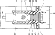
图2是本发明的一实施方式的电动机的沿着图1的A-A截面的剖视图。Fig. 2 is a sectional view of the motor according to the embodiment of the present invention along the A-A section in Fig. 1 .

图3是本发明的一实施方式的组装了导通端子的端子保持构件的剖视图。FIG. 3 is a cross-sectional view of a terminal holding member incorporating conduction terminals according to an embodiment of the present invention.

图4是本发明的一实施方式的端子保持构件的立体图。Fig. 4 is a perspective view of a terminal holding member according to an embodiment of the present invention.

图5是本发明的一实施方式的端子保持构件的仰视图。Fig. 5 is a bottom view of a terminal holding member according to an embodiment of the present invention.

图6是本发明的一实施方式的导通端子的立体图。6 is a perspective view of a conduction terminal according to an embodiment of the present invention.

图7是本发明的一实施方式的导通端子的侧视图。FIG. 7 is a side view of a conduction terminal according to an embodiment of the present invention.

图8是从斜下方观察本发明的一实施方式的端子保持构件而得到的立体图。8 is a perspective view of the terminal holding member according to the embodiment of the present invention viewed obliquely from below.

图9是将比较例的突起的应力分布图(A)和本发明的一实施方式的突起的应力分布图(B)一并记载的图。9 is a diagram showing a stress distribution diagram (A) of a protrusion of a comparative example and a stress distribution diagram (B) of a protrusion according to an embodiment of the present invention.

图10是将比较例的贯通孔的周边部的应力分布图(A)和本发明的一实施方式的贯通孔的周边部的应力分布图(B)一并记载的图。10 is a diagram showing a stress distribution diagram (A) of a peripheral portion of a through-hole in a comparative example and a stress distribution diagram (B) of a peripheral portion of a through-hole according to an embodiment of the present invention.

图11是本发明的一实施方式的电动机的沿着图2的B-B截面的剖视图。Fig. 11 is a cross-sectional view of the motor according to the embodiment of the present invention along the B-B cross section of Fig. 2 .

图12是将本发明的一实施方式的导通端子的组装方法按照(A)~(E)顺次表示的剖视图。12 is a cross-sectional view sequentially showing the method of assembling the conduction terminal according to the embodiment of the present invention (A) to (E).

图13是本发明的另一实施方式的导通端子和端子保持构件的剖视图。13 is a sectional view of a conduction terminal and a terminal holding member according to another embodiment of the present invention.

【符号说明】【Symbol Description】

1…电动机1…Electric motor

2…电动机壳体2…Motor housing

7…第一端子保持构件7...first terminal holding member

10,110…导通端子10, 110... Conduction terminal

13…端子安装孔13...Terminal mounting holes

26…密封圈(密封构件)26...Sealing ring (sealing member)

35…延伸壁35…Extended wall

36…作业孔(第二贯通孔)36...Working hole (second through hole)

37、137…突起37, 137...Protrusions

38…贯通孔38...Through hole

40…定位部40...Positioning Department

具体实施方式Detailed ways

以下,基于图1~图12,对本发明的一实施方式进行说明。Hereinafter, an embodiment of the present invention will be described based on FIGS. 1 to 12 .

图1是表示该实施方式的电动机1的外观的立体图,图2是与图1的A A截面部分对应的剖视图。需要说明的是,在以下的说明中,只要没有特别限定,就将与图1中的上侧相当的一侧称为“上”,将其相反侧称为“下”。FIG. 1 is a perspective view showing the appearance of a motor 1 according to this embodiment, and FIG. 2 is a cross-sectional view corresponding to the AA section of FIG. 1 . In the following description, unless otherwise specified, the side corresponding to the upper side in FIG. 1 will be referred to as "upper", and the opposite side will be referred to as "lower".

该实施方式的电动机1是作为混合动力车或电动机动车的驱动源而使用的电动机,在由铝合金等金属材料构成的电动机壳体2的内部固定配置有圆环状的未图示的定子,并且在定子的内侧配置有可旋转的未图示的转子。在定子上卷绕有U相、V相、W相这三相的导线4,该各相的导线4的端部被引出到定子的外侧,并在电动机壳体2的轴向的一端部的上部侧区域分别与从电动机壳体2的外部引入的对应相的供电线5连接。The electric motor 1 of this embodiment is an electric motor used as a driving source of a hybrid vehicle or an electric vehicle, and an annular stator (not shown) is fixedly disposed inside a motor case 2 made of a metal material such as aluminum alloy. In addition, a rotor (not shown) is rotatably disposed inside the stator. Three-phase wires 4 of U-phase, V-phase, and W-phase are wound on the stator, and the ends of the wires 4 of each phase are drawn out to the outside of the stator, and at one end of the axial direction of the motor case 2 The upper side regions are respectively connected to the power supply lines 5 of the corresponding phases introduced from the outside of the motor housing 2 .

如图2所示,在电动机壳体2的轴向的一端侧的上部设有端子设置部6,该端子设置部6具备大致扁平的上壁6a和与该上壁6a连设的端部壁6b。在端子设置部6的端部壁6b和上壁6a上分别安装有由绝缘性的树脂材料构成的第一端子保持构件7和第二端子保持构件8。在第一端子保持构件7中保持有在一端侧分别连接定子侧的各相的导线4的端子9(以下,称为“线圈端子9”。)的金属制的三个导通端子10。As shown in FIG. 2 , a terminal installation portion 6 is provided on an upper portion of one axial end side of the motor case 2 . The terminal installation portion 6 includes a substantially flat upper wall 6 a and an end wall connected to the upper wall 6 a. 6b. A first terminal holding member 7 and a second terminal holding member 8 made of an insulating resin material are attached to the end wall 6 b and the upper wall 6 a of the terminal installation portion 6 , respectively. The first terminal holding member 7 holds three conductive terminals 10 made of metal to which terminals 9 (hereinafter referred to as “coil terminals 9 ”) are respectively connected to the lead wires 4 of the respective phases on the stator side at one end side.

图3是表示保持有导通端子10的第一端子保持构件7的图,图4、图5是表示第一端子保持构件7的单体的图。FIG. 3 is a diagram showing the first terminal holding member 7 holding the conduction terminal 10 , and FIGS. 4 and 5 are diagrams showing the first terminal holding member 7 alone.

如这些图所示,第一端子保持构件7包括:相对于端部壁6b从电动机壳体2的外侧重叠安装的基座壁7a;从该基座壁7a向大致直角方向突出,且在其内部插入有对应的导通端子10的大致圆筒状的三个突起部7b。三个突起部7b等间隔地并排突出设置。As shown in these figures, the first terminal holding member 7 includes: a base wall 7a installed overlappingly with the end wall 6b from the outside of the motor case 2; Three substantially cylindrical protrusions 7 b corresponding to the conduction terminals 10 are inserted therein. The three protrusions 7b protrude side by side at equal intervals.

另外,在端子设置部6的端部壁6b上与第一端子保持构件7的三个突起部7b对应而形成有三个贯通孔11,在该各贯通孔11中插入第一端子保持构件7的对应的突起部7b。第一端子保持构件7在将三个突起部7b插入到贯通孔11中的状态下,将基座壁7a螺栓紧固连结于端部壁6b。另外,在各突起部7b与对应的贯通孔11之间安装有密封圈12,来实现两者之间的密闭。In addition, three through-holes 11 are formed on the end wall 6b of the terminal installation part 6 corresponding to the three protrusions 7b of the first terminal holding member 7, and the holes of the first terminal holding member 7 are inserted into the through-holes 11. Corresponding protrusion 7b. In the first terminal holding member 7 , the base wall 7 a is bolt-fastened to the end wall 6 b in a state where the three protrusions 7 b are inserted into the through holes 11 . In addition, a seal ring 12 is installed between each protrusion 7 b and the corresponding through-hole 11 to realize airtight sealing between the two.

在插入到端子设置部6的各贯通孔11中的突起部7b上设有沿轴向贯通的端子安装孔13,如图2所示,在该各端子安装孔13中插入导通端子10。对于插入到端子安装孔13中的各导通端子10来说,在配置于电动机壳体2的内侧的前端部上连接有对应相的线圈端子9,并且在配置于电动机壳体2的外侧的基端部上连接有由导电性的金属板构成的母线14。各母线14从与导通端子10连接的连接部向上方延伸,延伸的上端部侧在第二端子保持构件8上与对应相的供电线5的端子15(以下、称为“供电端子15”。)连接。The protrusions 7 b inserted into the through holes 11 of the terminal installation part 6 are provided with terminal mounting holes 13 penetrating in the axial direction, and the conduction terminals 10 are inserted into the respective terminal mounting holes 13 as shown in FIG. 2 . For each conduction terminal 10 inserted into the terminal mounting hole 13, the coil terminal 9 of the corresponding phase is connected to the front end portion arranged inside the motor case 2, and the coil terminal 9 arranged outside the motor case 2 A bus bar 14 made of a conductive metal plate is connected to the base end. Each bus bar 14 extends upward from the connection portion connected to the conduction terminal 10, and the extended upper end side is connected to the terminal 15 of the power supply line 5 of the corresponding phase on the second terminal holding member 8 (hereinafter referred to as "power supply terminal 15"). .)connect.

需要说明的是,如图4所示,在第一端子保持构件7的基座壁7a上形成有围绕各导通端子10的基端部与母线14的连接部的周围的大致U字状的隔壁16,通过该各隔壁16将连接部和母线14遮蔽而从外部电性地隔离。It should be noted that, as shown in FIG. 4 , on the base wall 7 a of the first terminal holding member 7 , there is formed a substantially U-shaped groove surrounding the connection portion between the base end portion of each conduction terminal 10 and the bus bar 14 . The partition wall 16 shields the connection portion and the bus bar 14 by each partition wall 16 and electrically isolates it from the outside.

另外,在端子设置部6的上壁6a上并排设有三个作业孔17。所述各作业孔17配置在三个导通端子10的前端部与线圈端子9的连接部的正上方位置,其用于在通过螺栓18将线圈端子9紧固于导通端子10时,通过工具来进行紧固作业。In addition, three working holes 17 are provided in parallel on the upper wall 6 a of the terminal installation portion 6 . The working holes 17 are arranged directly above the connecting parts between the front ends of the three conduction terminals 10 and the coil terminals 9, and are used to pass through when the coil terminals 9 are fastened to the conduction terminals 10 by bolts 18 tools for fastening work.

在第二端子保持构件8上设有插入到上述三个作业孔17中的盖部19、与将母线14的上端部和供电端子10连接的螺栓20螺合的螺纹承接部21。需要说明的是,图2中,22是安装在盖部19与作业孔17之间的密封圈,23是埋设在第二端子保持构件8的螺纹承接部21中的螺母。The second terminal holding member 8 is provided with a cover portion 19 inserted into the three working holes 17 and a screw receiving portion 21 screwed to the bolt 20 connecting the upper end portion of the bus bar 14 and the power supply terminal 10 . It should be noted that, in FIG. 2 , 22 is a seal ring installed between the cover portion 19 and the working hole 17 , and 23 is a nut embedded in the screw receiving portion 21 of the second terminal holding member 8 .

图6、图7是表示导通端子10的外表面形状的图。6 and 7 are diagrams showing the outer surface shape of the conduction terminal 10 .

如图2、图3及上述图所示,导通端子10的基本形状形成为圆柱状,轴向的基部侧的大致三分之一的区域形成为插入到第一端子保持构件7的端子安装孔13中的嵌合部24,在该嵌合部24的外周形成有环状的保持槽25。在该保持槽25中安装有用于将端子安装孔13与导通端子10之间密闭的密封圈26(密封构件)。As shown in FIG. 2, FIG. 3 and the above-mentioned figures, the basic shape of the conduction terminal 10 is formed in a cylindrical shape, and approximately one-third of the area on the base side in the axial direction is formed as a terminal mounting area inserted into the first terminal holding member 7. The fitting portion 24 in the hole 13 has an annular holding groove 25 formed on the outer periphery of the fitting portion 24 . A seal ring 26 (sealing member) for sealing between the terminal attachment hole 13 and the conduction terminal 10 is attached to the holding groove 25 .

导通端子10的轴向的前端部侧的大致三分之二的区域的上部(如图2所示,安装到电动机壳体2上时成为上侧的部分)被水平切除,形成平坦的接合面27。在该接合面27上重叠接合线圈端子9。接合面27的切除以使接合面27成为导通端子10的基本形状即圆柱形状的大致三分之二的高度的方式设定。The upper portion of the approximately two-thirds area of the front end side in the axial direction of the conduction terminal 10 (as shown in FIG. 2, the upper side when mounted on the motor case 2) is cut horizontally to form a flat junction. Face 27. The coil terminal 9 is overlapped and bonded on the bonding surface 27 . The cutting of the joint surface 27 is set so that the height of the joint surface 27 becomes approximately two-thirds of the cylindrical shape which is the basic shape of the conduction terminal 10 .

另外,在导通端子10的前端部附近的外周区域(除了接合面27的切除部分。)设置有设定宽度的切除槽28,并且在导通端子10的轴向的前端侧的大致三分之二的区域的下表面设置有前端侧与切除槽28连续的水平的切除面29。通过所述切除槽28和切除面29,在导通端子10的前端侧的下方区域形成从切除槽28的前端部向下方侧相对地凸起的第一卡止壁30和从切除面29的后端部向下方相对地凸起的第二卡止壁31。In addition, a cutout groove 28 with a set width is provided in the outer peripheral region near the front end of the conduction terminal 10 (excluding the cutout portion of the joint surface 27 ), and approximately three-thirds of the front end side in the axial direction of the conduction terminal 10 is formed. The lower surface of the second region is provided with a horizontal cutout surface 29 whose front end side is continuous with the cutout groove 28 . Through the cutout groove 28 and the cutout surface 29 , the first locking wall 30 protruding from the front end of the cutout groove 28 to the lower side and the first locking wall 30 protruding from the cutout surface 29 are formed in the lower area of the front end side of the conduction terminal 10 . The second locking wall 31 protrudes downward at the rear end.

需要说明的是,图中符号32是在导通端子10的前端侧区域设置且用于供结合线圈端子9的螺栓18螺合的螺纹孔,符号33是在导通端子10的基端面设置且用于供结合母线14的螺栓34(参照图2。)螺合的螺纹孔。It should be noted that the symbol 32 in the figure is a threaded hole provided on the front end side of the conduction terminal 10 and used for screwing the bolt 18 coupled with the coil terminal 9, and the symbol 33 is provided on the base end surface of the conduction terminal 10 and A threaded hole for screwing a bolt 34 (see FIG. 2 ) that connects the bus bar 14 .

此外,如图2、图3所示,在第一端子保持构件7的各突起部7b的前端部(配置在电动机壳体2的内侧这一侧的端部)设置有从端子安装孔13的形成部的周围区域沿轴向延伸的大致圆筒状的延伸壁35,该延伸壁35遮蔽导通端子10与线圈端子9的连接部的周围区域。但是,在延伸壁35的上部区域的导通端子10与线圈端子9的连接部的正上方位置设有作业孔36(第二贯通孔)。该作业孔36设置在与端子设置部6的上壁6a的作业孔17一致的位置,从而通过两作业孔17、36进行螺栓18的拧入作业。In addition, as shown in FIG. 2 and FIG. 3 , at the front end portion (the end portion disposed on the inner side of the motor case 2 ) of each protrusion portion 7 b of the first terminal holding member 7 , there is a mounting hole 13 from the terminal mounting hole 13 . A substantially cylindrical extension wall 35 extending in the axial direction in the peripheral area of the portion is formed, and the extended wall 35 shields the peripheral area of the connecting portion between the conduction terminal 10 and the coil terminal 9 . However, a working hole 36 (second through hole) is provided in an upper region of the extension wall 35 immediately above the connection portion between the conduction terminal 10 and the coil terminal 9 . The working hole 36 is provided at a position corresponding to the working hole 17 of the upper wall 6 a of the terminal installation portion 6 , and the bolt 18 is screwed in through the working holes 17 and 36 .

另外,在各突起部7b的延伸壁35的下部区域突出设置有向延伸壁35的圆筒内突出的突起37。该突起37形成为大致一定宽度的板状,从导通端子10与线圈端子9的连接部的大致正下方位置向上方突出规定高度后朝向延伸壁35的延伸方向向斜上方弯曲。In addition, a protrusion 37 protruding into the cylinder of the extension wall 35 is protruded from the lower region of the extension wall 35 of each protrusion 7b. The protrusion 37 is formed in a plate shape with a substantially constant width, protrudes upward by a predetermined height from a position substantially directly below the connection portion of the conduction terminal 10 and the coil terminal 9 , and then bends obliquely upward toward the extending direction of the extension wall 35 .

在导通端子10插入到端子安装孔13内规定深度以上时,该突起37被导通端子10的前端侧下端的角部按压而发生挠曲变形,突起37的前端部越过导通端子10的前端部而进行弹性复原时,与第一卡止壁30的内侧端面抵接。因此导通端子10的脱落方向的位移受到限制。When the conduction terminal 10 is inserted into the terminal installation hole 13 to a predetermined depth or more, the protrusion 37 is pressed by the corner of the lower end of the front end side of the conduction terminal 10 to deform, and the front end of the protrusion 37 goes over the edge of the conduction terminal 10. When the front end is elastically restored, it comes into contact with the inner end surface of the first locking wall 30 . Therefore, the displacement in the drop-off direction of the conduction terminal 10 is restricted.

图8是从下方观察延伸壁35的突起37的立起部附近而得到的图。FIG. 8 is a diagram in which the vicinity of the raised portion of the protrusion 37 of the extension wall 35 is viewed from below.

如图8和图5所示,在延伸壁35的突起37的立起部的周围区域形成有正面观察下呈大致コ状的贯通孔38。该贯通孔38通过形成为大致コ状而形成从延伸壁35的前端部侧朝向突起37的立起部延伸的长条状的挠曲片39(挠曲允许部)。对于该挠曲片39来说,在突起37上施加有载荷时,挠曲片39与突起37一起挠曲,由此使作用于突起37的应力分散。As shown in FIGS. 8 and 5 , a through-hole 38 having a substantially U-shape in front view is formed in a region around the raised portion of the protrusion 37 of the extension wall 35 . The through-hole 38 is formed in a substantially U-shape to form an elongated bending piece 39 (bending allowing portion) extending from the front end side of the extension wall 35 toward the rising portion of the protrusion 37 . In this flexure piece 39 , when a load is applied to the protrusion 37 , the flexure piece 39 flexes together with the protrusion 37 , thereby dispersing the stress acting on the protrusion 37 .

图9(A)是在延伸壁35上未设置贯通孔38时的突起37的周边部的应力分布图,图9(B)是在延伸壁35上设置了贯通孔38时的突起37的周边部的应力分布图。9(A) is a stress distribution diagram around the protrusion 37 when no through hole 38 is provided on the extension wall 35, and FIG. 9(B) is a diagram around the protrusion 37 when the through hole 38 is provided on the extension wall 35. The stress distribution diagram of the part.

由这些图也可知,在延伸壁35上未设置贯通孔38时,在突起37的立起部附近的弯曲部分产生应力集中,而在延伸壁35上设置了贯通孔38时,能够使作用于突起37的应力分散到整个周围区域。It can also be seen from these figures that when the extension wall 35 is not provided with the through-hole 38, stress concentration occurs at the curved portion near the upright portion of the protrusion 37, but when the extension wall 35 is provided with the through-hole 38, the force acting on The stress of the protrusion 37 is distributed to the entire surrounding area.

另外,设置在延伸壁35上的贯通孔38的コ状的开口侧的末端附近的形状不是单纯的一定宽度的开口,而是宽度朝向コ状的开口侧扩宽成末端扩宽状,且末端部38a描绘出以突起37的立起部附近为中心的圆弧,并经由曲率半径大的圆弧部38c与沿着延伸壁35的轴向的孔缘38b连续。In addition, the shape near the end of the U-shaped opening side of the through-hole 38 provided on the extension wall 35 is not simply an opening with a constant width, but the width is widened toward the U-shaped opening side to form a widened end shape, and the end The portion 38a describes an arc centered around the vicinity of the raised portion of the protrusion 37, and is continuous with the hole edge 38b along the axial direction of the extension wall 35 via an arc portion 38c having a large curvature radius.

图10(A)是贯通孔38的コ状的开口侧的末端附近的形状为单纯的一定宽度的开口时的应力分布图,图10(B)是贯通孔38的コ状的开口侧的端部附近的形状如上所述那样设定时的应力分布图。另外,图11是用于说明通过螺栓18将线圈端子9紧固于导通端子10时作用于第一端子保持构件7的载荷的图。10(A) is a stress distribution diagram when the shape near the end of the U-shaped opening side of the through-hole 38 is a simple opening with a constant width, and FIG. 10(B) is the end of the U-shaped opening side of the through-hole 38. Stress distribution diagram when the shape of the vicinity of the portion is set as described above. In addition, FIG. 11 is a diagram for explaining the load acting on the first terminal holding member 7 when the coil terminal 9 is fastened to the conduction terminal 10 with the bolt 18 .

在此假想的作用于第一端子块7的应力是如图11所示通过螺栓18将线圈端子9紧固于导通端子10时从线圈端子9作用于延伸壁35的转矩所引起的应力。The virtual stress acting on the first terminal block 7 here is the stress caused by the torque acting on the extension wall 35 from the coil terminal 9 when the coil terminal 9 is fastened to the conduction terminal 10 with the bolt 18 as shown in FIG. 11 . .

如图10(A)所示,在贯通孔38的コ状的开口侧的末端附近形成为单纯的一定宽度的开口形状时,在末端部附近容易产生应力集中,而如图10(B)所示,在贯通孔38的コ状的开口侧的末端附近形成为宽度朝向前端部扩宽成末端扩宽状,且末端部38a描绘出以突起37的立起部附近(螺栓18的紧固部附近)为中心的圆弧,并经由曲率半径大的圆弧部38c与沿着延伸壁35的轴向的孔缘38b连续的形状时,能够将作用于延伸壁35的应力分散到贯通孔38周围的大范围内。As shown in FIG. 10(A), when the through-hole 38 is formed in a simple opening shape with a constant width near the end of the U-shaped opening side, stress concentration is likely to occur near the end portion. However, as shown in FIG. 10(B), As shown, in the vicinity of the end of the U-shaped opening side of the through hole 38, the width is widened toward the front end to form a widened end, and the end portion 38a is drawn in the vicinity of the upright portion of the protrusion 37 (the fastening portion of the bolt 18). When the shape is a circular arc centered on the center of the extension wall 35 through the arc portion 38c with a large radius of curvature and the hole edge 38b along the axial direction of the extension wall 35, the stress acting on the extension wall 35 can be distributed to the through hole 38. in a large area around.

另外,如图2、图3所示,在各突起部7b的端子安装孔13内,在延伸壁35侧的端部附近设有向上方凸起规定高度的定位部40。在导通端子10插入到端子安装孔13中达规定深度时,该定位部40与导通端子10的第二卡止壁31抵接,由此限制导通端子10的插入方向的位移。需要说明的是,定位部40的上表面形成为水平的扁平面。In addition, as shown in FIG. 2 and FIG. 3 , in the terminal mounting hole 13 of each protruding portion 7b, a positioning portion 40 protruding upward by a predetermined height is provided near the end portion on the extension wall 35 side. When the conduction terminal 10 is inserted into the terminal mounting hole 13 to a predetermined depth, the positioning portion 40 contacts the second locking wall 31 of the conduction terminal 10 , thereby restricting the displacement of the conduction terminal 10 in the insertion direction. It should be noted that the upper surface of the positioning portion 40 is formed as a horizontal flat surface.

此外,在该实施方式的导通端子10和第一端子保持构件7的情况下,如图3所示,卡止于突起37的第一卡止壁30和卡止于定位部40的第二卡止壁31隔着切除槽28和切除面29设定在同一高度上。因此,在要将导通端子10直接插入到端子安装孔13中时,导通端子10的前端侧的卡止壁30与端子安装孔13内的定位部40抵接,从而导通端子10无法进行进一步的插入。In addition, in the case of the conduction terminal 10 and the first terminal holding member 7 of this embodiment, as shown in FIG. The locking wall 31 is set at the same height across the cutout groove 28 and the cutout surface 29 . Therefore, when the conduction terminal 10 is to be directly inserted into the terminal installation hole 13, the locking wall 30 on the front end side of the conduction terminal 10 abuts against the positioning portion 40 in the terminal installation hole 13, so that the conduction terminal 10 cannot be inserted into the terminal installation hole 13. Make further insertions.

因此,在将导通端子10向第一端子保持构件7组装时,采用如图12(A)~(E)所示那样的方法。Therefore, when assembling the conduction terminal 10 to the first terminal holding member 7, a method as shown in FIGS. 12(A) to (E) is employed.

以下,对图12所示的组装方法进行说明。需要说明的是,在导通端子10的保持槽25中预先安装密封圈26。Hereinafter, the assembly method shown in FIG. 12 will be described. It should be noted that the sealing ring 26 is preinstalled in the holding groove 25 of the conduction terminal 10 .

首先,如图12(A)所示,使导通端子10相对于最终组装姿态反转大致180°,从而使导通端子10的第一卡止壁30来到上部侧,在该姿态下将导通端子10的前端侧插入到第一端子保持构件7的端子安装孔13内。此时,第一卡止壁30的外侧的圆弧面在端子安装孔13内的没有定位部40的上部区域滑动。导通端子10以该姿态插入到第一卡止壁30穿出到端子安装孔13的外侧为止。First, as shown in FIG. 12(A), the conduction terminal 10 is reversed approximately 180° relative to the final assembly posture so that the first locking wall 30 of the conduction terminal 10 comes to the upper side. The front end side of the conduction terminal 10 is inserted into the terminal mounting hole 13 of the first terminal holding member 7 . At this time, the outer arcuate surface of the first locking wall 30 slides in the upper region of the terminal mounting hole 13 without the positioning portion 40 . The conduction terminal 10 is inserted in this posture until the first locking wall 30 protrudes to the outside of the terminal mounting hole 13 .

接着,当第一卡止壁30穿出到端子安装孔13的外侧时,在该时刻如图12(B)、(C)、(D)依次表示的那样,使导通端子10旋转180°而形成为最终组装姿态。这样,当使导通端子10旋转到最终组装姿态时,导通端子10的第一卡止壁30处于在轴向上与定位部40重叠的范围,但位于定位部40的前端侧。Next, when the first locking wall 30 passes out to the outside of the terminal mounting hole 13, at this moment, as shown in sequence in Figure 12 (B), (C), (D), the conduction terminal 10 is rotated 180° And formed into the final assembly posture. In this way, when the conduction terminal 10 is rotated to the final assembly posture, the first locking wall 30 of the conduction terminal 10 is in the range overlapping the positioning portion 40 in the axial direction, but is located on the front end side of the positioning portion 40 .

随后,在将导通端子10维持最终组装姿态的状态下向端子安装孔13内进一步插入。在这样将导通端子10进一步插入到端子安装孔13内时,导通端子10的前端部下方的角部部分与延伸壁35上的突起37抵接而使突起37挠曲变形。这样,当将导通端子10插入到规定位置时,如图12(E)所示,突起37越过第一卡止壁30的圆弧面而其前端部与第一卡止壁30的内侧端面抵接,并且第二卡止壁31与端子安装孔13内的定位部40抵接。Subsequently, the conduction terminal 10 is further inserted into the terminal mounting hole 13 while maintaining the final assembled posture. When the conduction terminal 10 is further inserted into the terminal mounting hole 13 in this way, the corner portion below the front end of the conduction terminal 10 abuts on the protrusion 37 on the extension wall 35 to bend and deform the protrusion 37 . In this way, when the conduction terminal 10 is inserted to a predetermined position, as shown in FIG. and the second locking wall 31 is in contact with the positioning portion 40 in the terminal installation hole 13 .

其结果,导通端子10的相对于端子安装孔13的脱落方向和侵入方向的位移被突起37和定位部40限制。As a result, the displacement of the conduction terminal 10 in the falling direction and the entering direction with respect to the terminal mounting hole 13 is restricted by the protrusion 37 and the positioning portion 40 .

在此说明的导通端子10相对于第一端子保持构件7的组装是在将第一端子保持构件7安装到电动机壳体2的端子设置部6上之前进行的。并且,在将预先组装了导通端子10的第一端子保持构件7安装到电动机壳体2的端子设置部6上之后,通过作业孔17、36进行各线圈端子9与导通端子10的结合,之后在端子设置部6上组装第二端子保持构件8,进行母线14的下端部相对于导通端子10的结合以及母线14的上端部与供电端子15的结合。The assembly of the conduction terminal 10 described here with the first terminal holding member 7 is performed before the first terminal holding member 7 is attached to the terminal installation portion 6 of the motor case 2 . And, after attaching the first terminal holding member 7 in which the conduction terminal 10 is preassembled to the terminal installation part 6 of the motor case 2, the connection of each coil terminal 9 and the conduction terminal 10 is performed through the working holes 17, 36. Afterwards, the second terminal holding member 8 is assembled on the terminal setting part 6, and the lower end of the bus bar 14 is combined with the conduction terminal 10 and the upper end of the bus bar 14 is combined with the power supply terminal 15.

并且,当这样使所有的接线完成时,如图2所示,在端子设置部6的上部安装覆盖母线14及接线部等的周围的金属制的保护罩41。需要说明的是,在该保护罩41的内表面通过烧结固接有绝缘性的橡胶构件42。该橡胶构件42提高金属制的保护罩41相对于母线14及接线部等的绝缘性,由此能够实现保护罩41的小型化,并且万一保护罩41破损时能够抑制碎片散落。Then, when all the wiring is completed in this way, as shown in FIG. 2 , a metal protective cover 41 is attached to the upper part of the terminal installation part 6 to cover the periphery of the bus bar 14 and the connection parts. It should be noted that an insulating rubber member 42 is fixed to the inner surface of the protective cover 41 by sintering. The rubber member 42 improves the insulation of the metal protective cover 41 with respect to the bus bars 14 and connection parts, thereby enabling the protective cover 41 to be downsized and suppressing fragments from being scattered when the protective cover 41 is damaged.

如上所述,在该实施方式的电动机1中,第一端子保持构件7的各端子安装孔13与对应的导通端子10之间由密封圈26密闭,并且导通端子10从各端子安装孔13的脱落由第一端子保持构件7上的突起37限制,因此即使发生线膨胀系数不同的第一端子保持构件7和导通端子10的热伸缩,也能够将第一端子保持构件7的端子安装孔13与导通端子10之间始终以恒定状态稳定地密闭。As described above, in the motor 1 of this embodiment, the gap between each terminal mounting hole 13 of the first terminal holding member 7 and the corresponding conduction terminal 10 is sealed by the seal ring 26, and the conduction terminal 10 passes through each terminal mounting hole. 13 is restricted by the protrusion 37 on the first terminal holding member 7, so even if the thermal expansion and contraction of the first terminal holding member 7 and the conduction terminal 10 having different coefficients of linear expansion occur, the terminals of the first terminal holding member 7 can be held together. The gap between the mounting hole 13 and the conduction terminal 10 is always stably sealed in a constant state.

并且,在该实施方式中,导通端子10相对于各端子安装孔13的侵入方向的位移由设置在端子安装孔13内的定位部40限制,因此还能够限制导通端子10的向侵入方向的过大位移,从而能够将导通端子10更加稳定地保持为恒定状态。Moreover, in this embodiment, the displacement of the conduction terminal 10 relative to the intrusion direction of each terminal installation hole 13 is restricted by the positioning part 40 provided in the terminal installation hole 13, so the intrusion direction of the conduction terminal 10 can also be restricted. Excessive displacement, so that the conduction terminal 10 can be more stably maintained in a constant state.

因此,在该实施方式的电动机1中,能够始终恒定地维持各端子安装孔13与导通端子10之间的密闭性,且能够可靠地防止电动机壳体2内的冷却液向外部渗出。Therefore, in the motor 1 of this embodiment, the airtightness between each terminal attachment hole 13 and the conduction terminal 10 can be maintained constantly, and the coolant in the motor case 2 can be reliably prevented from seeping out.

另外,在该实施方式的电动机1中,各相的导通端子10与线圈端子9的连接部的周围区域由第一端子保持构件7的大致圆筒状的延伸壁35围绕,并且在延伸壁35中的所述连接部的下方区域突出设置有突起37,因此能够在实现导通端子10的连接部的周围区域的绝缘的同时,在第一端子保持构件7上的合适位置设定突起37。In addition, in the motor 1 of this embodiment, the surrounding area of the connecting portion of the conduction terminal 10 of each phase and the coil terminal 9 is surrounded by the substantially cylindrical extension wall 35 of the first terminal holding member 7, and the extension wall Protrusions 37 are protruded from the lower area of the connecting portion in 35, so that the protrusions 37 can be set at an appropriate position on the first terminal holding member 7 while realizing the insulation of the surrounding area of the connecting portion of the conduction terminal 10. .

另外,在该实施方式的电动机1中,在第一端子保持构件7上的延伸壁35的突起37的立起部的周围区域设有大致コ状的贯通孔38,通过该贯通孔38形成与突起37连续的挠曲片39,因此能够通过挠曲片39减少在突起37上产生的应力集中,从而将突起37的劣化防患于未然。In addition, in the motor 1 of this embodiment, a substantially U-shaped through-hole 38 is provided in the area around the upright portion of the protrusion 37 of the extension wall 35 on the first terminal holding member 7, and the through-hole 38 forms a Since the protrusion 37 is continuous with the flexure piece 39, the stress concentration on the protrusion 37 can be reduced by the flexure piece 39, thereby preventing deterioration of the protrusion 37 before it happens.

并且,在该电动机1中,能够将流入到延伸壁35内的电动机壳体2内的冷却液通过延伸壁35的下方区域的贯通孔38可靠地向下方排出。因此,通过采用该构造,能够消除因冷却液长期滞留在延伸壁35的内侧而引起的导通端子10与线圈端子9的连接部及第一端子保持构件7的劣化、冷却液自身的劣化、需要部位处的冷却液或润滑液的不足等不良情况。In addition, in this motor 1 , the coolant that has flowed into the motor case 2 in the extension wall 35 can be reliably discharged downward through the through hole 38 in the lower region of the extension wall 35 . Therefore, by adopting this structure, it is possible to eliminate deterioration of the connecting portion between the conduction terminal 10 and the coil terminal 9 and the first terminal holding member 7, deterioration of the cooling liquid itself, Bad conditions such as insufficient coolant or lubricant at the required parts.

此外,在该实施方式中,在大致圆筒状的延伸壁35的上部区域形成有作业孔36,因此能够在实现导通端子10的连接部的绝缘的同时,使线圈端子9与导通端子10的连接作业性良好。In addition, in this embodiment, since the working hole 36 is formed in the upper region of the substantially cylindrical extension wall 35, it is possible to insulate the connecting portion of the conduction terminal 10 and connect the coil terminal 9 to the conduction terminal. The connection workability of 10 was good.

需要说明的是,本发明不限定于上述实施方式,在不脱离其主旨的范围内可以进行各种设计变更。例如,在上述实施方式中,导通端子10上的第一卡止壁30和第二卡止壁31的高度设定为相同高度,因此需要采用图12所示那样的特殊的组装方法,但若如图13所示的另一实施方式那样,较高地设定前端侧的第一卡止壁130,与其对应而较高地设定突起137,则能够以最终组装姿态直接将导通端子110插入到对应的端子安装孔13内。在图13中,对与上述实施方式相同的部分标注同一符号,并省略了重复的说明。In addition, this invention is not limited to the said embodiment, Various design changes are possible in the range which does not deviate from the summary. For example, in the above-mentioned embodiment, the heights of the first locking wall 30 and the second locking wall 31 on the conduction terminal 10 are set to be the same height, so a special assembly method as shown in FIG. 12 is required, but If, as in another embodiment shown in FIG. 13 , the first locking wall 130 on the front end side is set higher, and the projection 137 is set higher correspondingly, the conduction terminal 110 can be directly inserted into the final assembly posture. into the corresponding terminal installation hole 13. In FIG. 13 , the same reference numerals are assigned to the same parts as those in the above-mentioned embodiment, and overlapping descriptions will be omitted.

Claims (6)

1.一种电动机,其具备:卷绕有导线的定子;在内部收容该定子的电动机壳体;由绝缘材料构成,且安装在所述电动机壳体上的端子保持构件;由该端子保持构件保持,一端侧在所述电动机壳体的内侧与所述定子的导线连接,另一端侧在所述电动机壳体的外侧与外部的供电线连接的导通端子,所述电动机的特征在于,1. A motor comprising: a stator wound with lead wires; a motor housing for accommodating the stator; a terminal holding member made of an insulating material and mounted on the motor housing; the terminal holding member holding a conduction terminal connected to the lead wire of the stator on the inside of the motor case at one end and connected to an external power supply line at the outside of the motor case at the other end side, the motor is characterized in that 在所述端子保持构件上以将所述电动机壳体的内外连通的方式形成有端子安装孔,在该端子安装孔中沿着规定的插入方向插入所述导通端子,且在所述端子安装孔与所述导通端子的插入部之间安装有密封构件,在所述端子保持构件上还设有突起,在将所述导通端子插入到所述端子安装孔中时,所述突起与所述导通端子卡合,来限制所述导通端子向所述插入方向的反方向的脱落。A terminal mounting hole is formed in the terminal holding member so as to connect the inside and outside of the motor case, and the conduction terminal is inserted into the terminal mounting hole along a predetermined insertion direction, and is mounted on the terminal. A sealing member is installed between the hole and the insertion portion of the conduction terminal, and a protrusion is provided on the terminal holding member. When the conduction terminal is inserted into the terminal installation hole, the protrusion and The conduction terminal is engaged to restrict the disengagement of the conduction terminal in a direction opposite to the insertion direction. 2.根据权利要求1所述的电动机,其特征在于,2. The electric motor according to claim 1, characterized in that, 在所述端子保持构件上设有定位部,在将所述导通端子插入到所述端子安装孔中时,所述定位部与所述导通端子抵接,来限制所述导通端子向所述插入方向的位移。The terminal holding member is provided with a positioning portion, and when the conduction terminal is inserted into the terminal installation hole, the positioning portion abuts on the conduction terminal to restrict the movement of the conduction terminal. displacement in the direction of insertion. 3.根据权利要求1或2所述的电动机,其特征在于,3. An electric motor according to claim 1 or 2, characterized in that, 在所述端子保持构件上设有延伸壁,该延伸壁比所述端子安装孔向所述电动机壳体的内侧方向延伸,且覆盖所述导通端子与所述定子的导线的连接部的至少下方区域,所述突起形成在所述延伸壁上。The terminal holding member is provided with an extension wall extending inwardly of the motor case beyond the terminal mounting hole and covering at least a portion of a connecting portion of the conduction terminal and the lead wire of the stator. In the lower area, the protrusion is formed on the extension wall. 4.根据权利要求3所述的电动机,其特征在于,4. The electric motor according to claim 3, characterized in that, 在所述延伸壁上的所述突起的立起部的周围形成有贯通孔。A through hole is formed around the rising portion of the protrusion on the extension wall. 5.根据权利要求4所述的电动机,其特征在于,5. The electric motor according to claim 4, characterized in that, 所述贯通孔形成为包围所述突起的大致コ状。The through hole is formed in a substantially U-shape surrounding the protrusion. 6.根据权利要求4或5所述的电动机,其特征在于,6. An electric motor according to claim 4 or 5, characterized in that, 所述延伸壁形成为覆盖所述导通端子与所述定子的导线的连接部的筒状,在该延伸壁的与所述贯通孔对置的上部区域形成有第二贯通孔。The extension wall is formed in a cylindrical shape covering a connection portion between the conduction terminal and the lead wire of the stator, and a second through hole is formed in an upper region of the extension wall that faces the through hole.
CN2012104956918A 2011-12-09 2012-11-28 electric motor Pending CN103166364A (en)

Applications Claiming Priority (2)

Application Number Priority Date Filing Date Title
JP2011270004A JP2013123286A (en) 2011-12-09 2011-12-09 Motor
JP2011-270004 2011-12-09

Publications (1)

Publication Number Publication Date
CN103166364A true CN103166364A (en) 2013-06-19

Family

ID=48571312

Family Applications (1)

Application Number Title Priority Date Filing Date
CN2012104956918A Pending CN103166364A (en) 2011-12-09 2012-11-28 electric motor

Country Status (3)

Country Link
US (1) US20130147293A1 (en)
JP (1) JP2013123286A (en)
CN (1) CN103166364A (en)

Cited By (3)

* Cited by examiner, † Cited by third party
Publication number Priority date Publication date Assignee Title
CN108023435A (en) * 2018-01-31 2018-05-11 江苏工大金凯高端装备制造有限公司 A kind of attachment device between electric mover and component
CN113991928A (en) * 2020-07-27 2022-01-28 株式会社电装 Actuator and vehicle operating system having the same
CN115349214A (en) * 2020-03-25 2022-11-15 日本电产株式会社 Motor

Families Citing this family (2)

* Cited by examiner, † Cited by third party
Publication number Priority date Publication date Assignee Title
JP6316463B1 (en) * 2017-01-24 2018-04-25 三菱電機株式会社 Electronic equipment unit
CN113489209A (en) * 2021-07-16 2021-10-08 珠海格力电器股份有限公司 Motor seal assembly and motor

Citations (6)

* Cited by examiner, † Cited by third party
Publication number Priority date Publication date Assignee Title
US4712029A (en) * 1986-12-22 1987-12-08 Sundstrand Corporation Generator high temperature electrical lead assembly
EP0703641A2 (en) * 1994-09-21 1996-03-27 Leopold Kostal GmbH & Co. KG Electrical connection member
JP2008148409A (en) * 2006-12-07 2008-06-26 Toyota Motor Corp Power connection structure for rotating electrical machine and method for manufacturing the same
CN101490929A (en) * 2006-07-12 2009-07-22 丰田自动车株式会社 motor assembly
JP2009284659A (en) * 2008-05-22 2009-12-03 Honda Motor Co Ltd Motor unit
CN101904058A (en) * 2007-12-18 2010-12-01 株式会社自动网络技术研究所 Connector and wire short-circuit method using the same

Family Cites Families (3)

* Cited by examiner, † Cited by third party
Publication number Priority date Publication date Assignee Title
JP3654272B2 (en) * 2002-08-26 2005-06-02 アイシン・エィ・ダブリュ株式会社 Wiring connection device for vehicle motor
JP5208578B2 (en) * 2008-05-22 2013-06-12 本田技研工業株式会社 Motor unit and method for manufacturing motor unit
US8648507B2 (en) * 2009-10-05 2014-02-11 Remy Technologies, L.L.C. Stator assembly including a terminal block for an electric machine

Patent Citations (6)

* Cited by examiner, † Cited by third party
Publication number Priority date Publication date Assignee Title
US4712029A (en) * 1986-12-22 1987-12-08 Sundstrand Corporation Generator high temperature electrical lead assembly
EP0703641A2 (en) * 1994-09-21 1996-03-27 Leopold Kostal GmbH & Co. KG Electrical connection member
CN101490929A (en) * 2006-07-12 2009-07-22 丰田自动车株式会社 motor assembly
JP2008148409A (en) * 2006-12-07 2008-06-26 Toyota Motor Corp Power connection structure for rotating electrical machine and method for manufacturing the same
CN101904058A (en) * 2007-12-18 2010-12-01 株式会社自动网络技术研究所 Connector and wire short-circuit method using the same
JP2009284659A (en) * 2008-05-22 2009-12-03 Honda Motor Co Ltd Motor unit

Cited By (3)

* Cited by examiner, † Cited by third party
Publication number Priority date Publication date Assignee Title
CN108023435A (en) * 2018-01-31 2018-05-11 江苏工大金凯高端装备制造有限公司 A kind of attachment device between electric mover and component
CN115349214A (en) * 2020-03-25 2022-11-15 日本电产株式会社 Motor
CN113991928A (en) * 2020-07-27 2022-01-28 株式会社电装 Actuator and vehicle operating system having the same

Also Published As

Publication number Publication date
US20130147293A1 (en) 2013-06-13
JP2013123286A (en) 2013-06-20

Similar Documents

Publication Publication Date Title
CN103025105B (en) Sealing structure for electronic-controlled installation
JP5410542B2 (en) Inverter terminal block installed in the motor case
US8272891B2 (en) Connector
CN101038995B (en) Connector construction
US11936251B2 (en) Electric compressor with inverter circuit section and filter circuit section
JP7005119B2 (en) connector
CN104584408B (en) Power inverter
US8358041B2 (en) Electric motor having wire connection structure and wire connection method for the same
JP5409517B2 (en) Electrical circuit device
CN103687394A (en) electronic control unit
JP6185826B2 (en) Motor connector and motor connector assembly
US6927522B2 (en) Power supply unit
CN103166364A (en) electric motor
JP2013097946A (en) Electrical connection structure with inverter and motor built-in drive train
JP2004327184A (en) Terminal board
US10389214B2 (en) Motor and producing method for motor
JP5937308B2 (en) Connector connection method
JP5538659B2 (en) Output terminal of electrical equipment
EP4122776A1 (en) Electronic control device
JP7174862B2 (en) stator assembly and motor
US11764632B2 (en) Electric compressor
CN115249928B (en) An integrated electrical connector based on shielding function
JP2021153001A (en) Terminal block
JP2011146159A (en) Connection structure
EP4518108A1 (en) Motor drive device for vehicle

Legal Events

Date Code Title Description
C06 Publication
PB01 Publication
C10 Entry into substantive examination
SE01 Entry into force of request for substantive examination
C02 Deemed withdrawal of patent application after publication (patent law 2001)
WD01 Invention patent application deemed withdrawn after publication

Application publication date: 20130619