EP4122666A1 - Smc manufacturing method - Google Patents
Smc manufacturing method Download PDFInfo
- Publication number
- EP4122666A1 EP4122666A1 EP21772392.3A EP21772392A EP4122666A1 EP 4122666 A1 EP4122666 A1 EP 4122666A1 EP 21772392 A EP21772392 A EP 21772392A EP 4122666 A1 EP4122666 A1 EP 4122666A1
- Authority
- EP
- European Patent Office
- Prior art keywords
- pin roller
- carbon fiber
- pin
- maximum radius
- roller
- Prior art date
- Legal status (The legal status is an assumption and is not a legal conclusion. Google has not performed a legal analysis and makes no representation as to the accuracy of the status listed.)
- Granted
Links
Images




Classifications
-
- B—PERFORMING OPERATIONS; TRANSPORTING
- B29—WORKING OF PLASTICS; WORKING OF SUBSTANCES IN A PLASTIC STATE IN GENERAL
- B29B—PREPARATION OR PRETREATMENT OF THE MATERIAL TO BE SHAPED; MAKING GRANULES OR PREFORMS; RECOVERY OF PLASTICS OR OTHER CONSTITUENTS OF WASTE MATERIAL CONTAINING PLASTICS
- B29B15/00—Pretreatment of the material to be shaped, not covered by groups B29B7/00 - B29B13/00
- B29B15/08—Pretreatment of the material to be shaped, not covered by groups B29B7/00 - B29B13/00 of reinforcements or fillers
- B29B15/10—Coating or impregnating independently of the moulding or shaping step
- B29B15/12—Coating or impregnating independently of the moulding or shaping step of reinforcements of indefinite length
- B29B15/122—Coating or impregnating independently of the moulding or shaping step of reinforcements of indefinite length with a matrix in liquid form, e.g. as melt, solution or latex
-
- C—CHEMISTRY; METALLURGY
- C08—ORGANIC MACROMOLECULAR COMPOUNDS; THEIR PREPARATION OR CHEMICAL WORKING-UP; COMPOSITIONS BASED THEREON
- C08J—WORKING-UP; GENERAL PROCESSES OF COMPOUNDING; AFTER-TREATMENT NOT COVERED BY SUBCLASSES C08B, C08C, C08F, C08G or C08H
- C08J5/00—Manufacture of articles or shaped materials containing macromolecular substances
- C08J5/24—Impregnating materials with prepolymers which can be polymerised in situ, e.g. manufacture of prepregs
- C08J5/241—Impregnating materials with prepolymers which can be polymerised in situ, e.g. manufacture of prepregs using inorganic fibres
- C08J5/243—Impregnating materials with prepolymers which can be polymerised in situ, e.g. manufacture of prepregs using inorganic fibres using carbon fibres
-
- B—PERFORMING OPERATIONS; TRANSPORTING
- B29—WORKING OF PLASTICS; WORKING OF SUBSTANCES IN A PLASTIC STATE IN GENERAL
- B29B—PREPARATION OR PRETREATMENT OF THE MATERIAL TO BE SHAPED; MAKING GRANULES OR PREFORMS; RECOVERY OF PLASTICS OR OTHER CONSTITUENTS OF WASTE MATERIAL CONTAINING PLASTICS
- B29B11/00—Making preforms
- B29B11/14—Making preforms characterised by structure or composition
- B29B11/16—Making preforms characterised by structure or composition comprising fillers or reinforcement
-
- B—PERFORMING OPERATIONS; TRANSPORTING
- B29—WORKING OF PLASTICS; WORKING OF SUBSTANCES IN A PLASTIC STATE IN GENERAL
- B29C—SHAPING OR JOINING OF PLASTICS; SHAPING OF MATERIAL IN A PLASTIC STATE, NOT OTHERWISE PROVIDED FOR; AFTER-TREATMENT OF THE SHAPED PRODUCTS, e.g. REPAIRING
- B29C70/00—Shaping composites, i.e. plastics material comprising reinforcements, fillers or preformed parts, e.g. inserts
- B29C70/04—Shaping composites, i.e. plastics material comprising reinforcements, fillers or preformed parts, e.g. inserts comprising reinforcements only, e.g. self-reinforcing plastics
- B29C70/06—Fibrous reinforcements only
- B29C70/10—Fibrous reinforcements only characterised by the structure of fibrous reinforcements, e.g. hollow fibres
- B29C70/12—Fibrous reinforcements only characterised by the structure of fibrous reinforcements, e.g. hollow fibres using fibres of short length, e.g. in the form of a mat
-
- B—PERFORMING OPERATIONS; TRANSPORTING
- B29—WORKING OF PLASTICS; WORKING OF SUBSTANCES IN A PLASTIC STATE IN GENERAL
- B29C—SHAPING OR JOINING OF PLASTICS; SHAPING OF MATERIAL IN A PLASTIC STATE, NOT OTHERWISE PROVIDED FOR; AFTER-TREATMENT OF THE SHAPED PRODUCTS, e.g. REPAIRING
- B29C70/00—Shaping composites, i.e. plastics material comprising reinforcements, fillers or preformed parts, e.g. inserts
- B29C70/04—Shaping composites, i.e. plastics material comprising reinforcements, fillers or preformed parts, e.g. inserts comprising reinforcements only, e.g. self-reinforcing plastics
- B29C70/28—Shaping operations therefor
- B29C70/40—Shaping or impregnating by compression not applied
- B29C70/50—Shaping or impregnating by compression not applied for producing articles of indefinite length, e.g. prepregs, sheet moulding compounds [SMC] or cross moulding compounds [XMC]
- B29C70/502—Shaping or impregnating by compression not applied for producing articles of indefinite length, e.g. prepregs, sheet moulding compounds [SMC] or cross moulding compounds [XMC] by first forming a mat composed of short fibres
-
- B—PERFORMING OPERATIONS; TRANSPORTING
- B29—WORKING OF PLASTICS; WORKING OF SUBSTANCES IN A PLASTIC STATE IN GENERAL
- B29C—SHAPING OR JOINING OF PLASTICS; SHAPING OF MATERIAL IN A PLASTIC STATE, NOT OTHERWISE PROVIDED FOR; AFTER-TREATMENT OF THE SHAPED PRODUCTS, e.g. REPAIRING
- B29C70/00—Shaping composites, i.e. plastics material comprising reinforcements, fillers or preformed parts, e.g. inserts
- B29C70/04—Shaping composites, i.e. plastics material comprising reinforcements, fillers or preformed parts, e.g. inserts comprising reinforcements only, e.g. self-reinforcing plastics
- B29C70/28—Shaping operations therefor
- B29C70/40—Shaping or impregnating by compression not applied
- B29C70/50—Shaping or impregnating by compression not applied for producing articles of indefinite length, e.g. prepregs, sheet moulding compounds [SMC] or cross moulding compounds [XMC]
- B29C70/504—Shaping or impregnating by compression not applied for producing articles of indefinite length, e.g. prepregs, sheet moulding compounds [SMC] or cross moulding compounds [XMC] using rollers or pressure bands
-
- C—CHEMISTRY; METALLURGY
- C08—ORGANIC MACROMOLECULAR COMPOUNDS; THEIR PREPARATION OR CHEMICAL WORKING-UP; COMPOSITIONS BASED THEREON
- C08J—WORKING-UP; GENERAL PROCESSES OF COMPOUNDING; AFTER-TREATMENT NOT COVERED BY SUBCLASSES C08B, C08C, C08F, C08G or C08H
- C08J5/00—Manufacture of articles or shaped materials containing macromolecular substances
- C08J5/04—Reinforcing macromolecular compounds with loose or coherent fibrous material
- C08J5/0405—Reinforcing macromolecular compounds with loose or coherent fibrous material with inorganic fibres
- C08J5/042—Reinforcing macromolecular compounds with loose or coherent fibrous material with inorganic fibres with carbon fibres
-
- D—TEXTILES; PAPER
- D01—NATURAL OR MAN-MADE THREADS OR FIBRES; SPINNING
- D01G—PRELIMINARY TREATMENT OF FIBRES, e.g. FOR SPINNING
- D01G1/00—Severing continuous filaments or long fibres, e.g. stapling
- D01G1/02—Severing continuous filaments or long fibres, e.g. stapling to form staple fibres not delivered in strand form
- D01G1/04—Severing continuous filaments or long fibres, e.g. stapling to form staple fibres not delivered in strand form by cutting
-
- D—TEXTILES; PAPER
- D02—YARNS; MECHANICAL FINISHING OF YARNS OR ROPES; WARPING OR BEAMING
- D02J—FINISHING OR DRESSING OF FILAMENTS, YARNS, THREADS, CORDS, ROPES OR THE LIKE
- D02J1/00—Modifying the structure or properties resulting from a particular structure; Modifying, retaining, or restoring the physical form or cross-sectional shape, e.g. by use of dies or squeeze rollers
- D02J1/18—Separating or spreading
-
- B—PERFORMING OPERATIONS; TRANSPORTING
- B29—WORKING OF PLASTICS; WORKING OF SUBSTANCES IN A PLASTIC STATE IN GENERAL
- B29K—INDEXING SCHEME ASSOCIATED WITH SUBCLASSES B29B, B29C OR B29D, RELATING TO MOULDING MATERIALS OR TO MATERIALS FOR MOULDS, REINFORCEMENTS, FILLERS OR PREFORMED PARTS, e.g. INSERTS
- B29K2307/00—Use of elements other than metals as reinforcement
- B29K2307/04—Carbon
-
- C—CHEMISTRY; METALLURGY
- C08—ORGANIC MACROMOLECULAR COMPOUNDS; THEIR PREPARATION OR CHEMICAL WORKING-UP; COMPOSITIONS BASED THEREON
- C08J—WORKING-UP; GENERAL PROCESSES OF COMPOUNDING; AFTER-TREATMENT NOT COVERED BY SUBCLASSES C08B, C08C, C08F, C08G or C08H
- C08J2300/00—Characterised by the use of unspecified polymers
- C08J2300/24—Thermosetting resins
-
- C—CHEMISTRY; METALLURGY
- C08—ORGANIC MACROMOLECULAR COMPOUNDS; THEIR PREPARATION OR CHEMICAL WORKING-UP; COMPOSITIONS BASED THEREON
- C08J—WORKING-UP; GENERAL PROCESSES OF COMPOUNDING; AFTER-TREATMENT NOT COVERED BY SUBCLASSES C08B, C08C, C08F, C08G or C08H
- C08J2363/00—Characterised by the use of epoxy resins; Derivatives of epoxy resins
-
- C—CHEMISTRY; METALLURGY
- C08—ORGANIC MACROMOLECULAR COMPOUNDS; THEIR PREPARATION OR CHEMICAL WORKING-UP; COMPOSITIONS BASED THEREON
- C08J—WORKING-UP; GENERAL PROCESSES OF COMPOUNDING; AFTER-TREATMENT NOT COVERED BY SUBCLASSES C08B, C08C, C08F, C08G or C08H
- C08J2367/00—Characterised by the use of polyesters obtained by reactions forming a carboxylic ester link in the main chain; Derivatives of such polymers
- C08J2367/06—Unsaturated polyesters
Definitions
- the present invention relates to a manufacturing method of an SMC (sheet molding compound), and particularly relates to a manufacturing method of a CF-SMC which is an SMC using carbon fiber (CF).
- SMC sheet molding compound
- CF carbon fiber
- CFRP carbon fiber reinforced plastic
- a certain type of CFRP products is molded from the CF-SMC by using a compression molding method.
- the CF-SMC is a type of carbon fiber prepregs, and has a structure in which a mat comprising chopped carbon fiber bundles (also referred to as a "chopped carbon fiber tow” or a “chopped carbon fiber strand”) is impregnated with a thermosetting resin composition.
- the CFRP has higher strength when being reinforced with a carbon fiber bundle having a smaller filament number.
- the carbon fiber bundle requires a higher manufacturing cost when having a smaller filament number (smaller tow size) (Patent Document 1).
- Patent Document 2 It is proposed adding a step of partially splitting a continuous carbon fiber bundle unwound from a creel before chopping to an SMC manufacturing method in which steps are continuously performed from chopping of the continuous carbon fiber bundle to resin impregnation of a carbon fiber mat.
- an SMC which can give a high-strength CFRP molded product can be manufactured at low cost by using a technique of partially splitting before use a continuous carbon fiber bundle having a large filament number, typically such as a large tow.
- the present invention is made in a process of studies performed by the present inventors, based on the above-described idea, and mainly aims to provide a useful improvement in a CF-SMC manufacturing technique including a CF-SMC manufacturing method in which a continuous carbon fiber bundle is partially split before use.
- An aspect of the present invention relates to an SMC manufacturing method.
- the SMC manufacturing method according to a preferred embodiment of the present invention includes, but not limited to the followings.
- a useful improvement in a CF-SMC manufacturing technique including an SMC manufacturing method in which a continuous carbon fiber is partially split before use.
- An SMC is a sheet-shaped carbon fiber prepreg obtainable by impregnating a carbon fiber mat comprising a chopped carbon fiber bundle with a thermosetting resin composition.
- One embodiment of the present invention is an SMC manufacturing method including the following steps (i) to (iv).
- fragmentation processing is performed so that at least some of the chopped carbon fiber bundles before being deposited on the carrier film is fragmented by being brought into contact with a rotating body.
- a distribution of the filament numbers of the chopped carbon fiber bundles included in the carbon fiber mat formed in the step (iii) above becomes different from that when the fragmentation processing is not performed.
- thermosetting resin composition When necessary, a step of thickening the thermosetting resin composition is further provided after the step (iv).
- a package of the continuous carbon fiber bundle prepared in advance is used.
- the continuous carbon fiber bundle has a filament number of NK and is partially split into n sub-bundles.
- NK means N ⁇ 1000.
- a filament number of a carbon fiber bundle comprising 3,000 single filaments is 3K, and a filament number of a carbon fiber bundle comprising 12,000 single filaments is 12K.
- N is usually 12 or more, preferably 15 or more, and can be, but not limited to 18, 24, 36, 48, or 50, for example.
- a continuous carbon fiber bundle is partially split into n sub-bundles, it means, in other words, that the continuous carbon fiber bundle is partially divided into n parts.
- Each of the n fiber bundles formed by dividing into n parts is called a sub-bundle.
- the package of the partially split continuous carbon fiber bundle can be manufactured using, but not limited to a fiber package manufacturing apparatus represented in a conceptual diagram in Fig. 1 .
- a fiber package manufacturing apparatus 100 includes a spread section 110, a split section 120, and a winding section 130.
- a continuous carbon fiber bundle 10 serving as a starting material and having a filament number of NK is drawn out from a supply bobbin B1.
- the continuous carbon fiber bundle 10 drawn out from the supply bobbin B1 before being split is first spread in the spread section 110.
- a spreader bar 111 provided in the spread section 110 may be heated and may be caused to reciprocate in a width direction of the continuous carbon fiber bundle 10. Mechanisms therefor can refer to a known technique.
- the continuous carbon fiber bundle 10 originally has a flat shape, it is further increased in width and further decreased in thickness by being rubbed against the spreader bar 111.
- the thickness of the continuous carbon fiber bundle 10 after passing through the spread section 110 is not limited, but can typically be 0.05 to 0.2 mm.
- the spread section 110 may be omitted, when the continuous carbon fiber bundle 10 is sufficiently flat at a stage when the continuous carbon fiber bundle 10 is supplied from the supply bobbin B1.
- a carbon fiber bundle having a bundle width of 50 times or more of an average thickness can be said to be sufficiently flat.
- the continuous carbon fiber bundle 10 is fed to the split section 120 and is partially split there.
- the split section 120 is provided with a rotary blade 121 for forming a slit in the continuous carbon fiber bundle 10 and a plurality of godet rolls 123 for controlling a traveling speed of the continuous carbon fiber bundle 10.
- a rotation axis of the rotary blade 121 is parallel to a width direction of the continuous carbon fiber bundle 10 traveling along a fiber direction.
- a plurality of blade parts 122 are provided at a regular interval in a circumferential direction on an outer circumference of the rotary blade 121, so that slits having a constant length are intermittently formed at a regular interval along the fiber direction of the continuous carbon fiber bundle 10.
- a slit length and a gap length between the slits can be controlled by adjusting the traveling speed of the continuous carbon fiber bundle 10, a circumferential speed of the rotary blade 121, and/or an interval between the blade portions 122.
- the continuous carbon fiber bundle 10 is partially divided into n parts due to intermittent formation of slits along the fiber direction by (n-1)-number of the rotary blades 121 aligned in a direction parallel to the width direction of the traveling continuous carbon fiber bundle 10.
- n is not limited to, but preferably 3 or more and more preferably 5 or more and may be 10 or more.
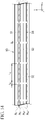
- Figs. 2A and 2B represent the continuous carbon fiber bundle 10 immediately after the slits extending in the fiber direction are intermittently formed by four rotary blades 121.
- the fiber direction (longitudinal direction) is defined as an x-direction
- the width direction is defined as a y-direction
- the thickness direction is defined as a z-direction
- Fig. 2A is a plan view when the continuous carbon fiber bundle 10 is viewed from the z-direction
- Fig. 2B represents a cross section of the continuous carbon fiber bundle 10 perpendicular to the x-direction (cross section when cut by an yz-plane).
- slit rows including a first slit row A S1 , a second slit row A S2 , a third slit row A S3 , and a fourth slit row A S4 are formed.
- the first slit row A S1 comprises a plurality of first slits S1 aligned in the x-direction.
- the second slit row A S2 comprises a plurality of second slits S2 aligned in the x-direction.
- the third slit row A S3 comprises a plurality of third slits S3 aligned in the x-direction.
- the fourth slit row A S4 comprises a plurality of fourth slits S4 aligned in the x-direction.
- the four slit rows are formed by different rotary blades and therefore are different from each other in positions in the y-direction.
- a slit length Ls and an inter-slit gap length L G are constant in any of the slit rows, and are common also among different slit rows.
- a ratio L S /(L S +L G ) of the slit length L S to a sum of the slit length L S and the inter-slit gap length L G is usually 90% or higher and preferably 95% or higher and may be 99% for example. Therefore, as represented in Fig. 2B , the continuous carbon fiber bundle 10 is split into five sub-bundles 11 in most parts.
- the positions of the first slit row A S1 , the second slit row A S2 , the third slit row A S3 , and the fourth slit row A S4 in the y-direction are set so that the widths of the five sub-bundles 11 are approximately the same.
- the filament number of the continuous carbon fiber bundle 10 is 15K
- the filament number of each of the sub-bundles 11 is 3K ⁇ 0.5K.
- the slit length Ls is not limited to, but preferably more than 25 mm, more preferably more than 50 mm, and much more preferably more than 500 mm.
- the slit length Ls can be 10 times or more, further 20 times or more, and further 30 times or more the cutting length when the continuous carbon fiber bundle 10 is cut to manufacture an SMC.
- the slit length Ls can be more than 25 mm and 50 mm or less, more than 50 mm and 100 mm or less, more than 100 mm and 200 mm or less, more than 200 mm and 500 mm or less, more than 500 mm and 1000 mm or less, more than 1000 mm and 1500 mm or less, more than 1500 mm and 2000 mm or less, and more than 2000 mm and 3000 mm or less.
- the inter-slit gap length L G is not limited to, but for example 5 to 10 mm and may be less than 5 mm.
- positions of inter-slit gaps Gs are shifted in the x-direction between the first slit row A S1 and the second slit row A S2 .
- Such a configuration with a shifting in the positions of the inter-slit gaps Gs in the x- direction between the adjacent slit rows is not essential.
- the positions of the inter-slit gaps Gs may be aligned among all of the slit rows as represented in Fig. 14 .
- the positions of the inter-slit gaps Gs may be aligned among some of the slit rows and shifted in the x-direction among some other slit rows.
- the slit length Ls, the inter-slit gap length L G , a ratio L S /(L S +L G ) of the slit length Ls to a sum of the slit length Ls and the inter-slit gap length L G , and the position of the inter-slit gap G S as described above are not limited to a case where the continuous carbon fiber bundle 10 is partially split into the five sub-bundles, and the same applies to a case where the continuous carbon fiber bundle 10 is partially split into four sub-bundles or less or six sub-bundles or more.
- the filament number of the sub-bundle formed by splitting the continuous carbon fiber bundle 10 is preferably 5K or less, more preferably 4K or less, and much more preferably 3K or less.
- the filament number of the sub-bundle formed by splitting the continuous carbon fiber bundle 10 is preferably more than 0.5K and more preferably 1K or more.
- the filament number is more than 0.5K, straightness of the carbon fiber bundle is likely to be maintained, and a reinforcing effect tends to be relatively high.
- the filament number of the sub-bundle formed by splitting the continuous carbon fiber bundle 10 is preferably 0.5K to 5K, more preferably 0.5K to 4K and much more preferably 1K to 3K.
- the continuous carbon fiber bundle 10 partially split into n parts in the split section 120 is fed to the winding section 130, and is wound on a winding bobbin B2, thereby completing the package.
- the winding bobbin B2 is a paper tube, but is not limited thereto.
- the winding bobbin B2 can be pulled out, and the continuous carbon fiber bundle can be unwound by internal unwinding.
- the continuous carbon fiber bundle 10 is wound such that there is no gap between the sub-bundles 11. The reason is to prevent the sub-bundles 11 from biting each other between a part previously wound on the bobbin B2 and a part wound later so as to overlap the previously wound part. By winding such that there is no gap between the sub-bundles 11, the continuous carbon fiber bundle 10 can be prevented from being entangled or broken during unwinding by external unwinding or internal unwinding.
- a total width W of the continuous carbon fiber bundle 10 may be made narrower than a sum of sub-bundle widths W s as represented in Fig. 3 .
- Fig. 3 is a sectional view when the continuous carbon fiber bundle 10 is cut perpendicular to the fiber direction, showing that the five sub-bundles 11 are arranged side by side without any gap in the y-direction. That is, there is no part where the adjacent sub-bundles 11 are away from each other, and each of the sub-bundles 11 overlaps the immediately adjacent sub-bundle 11 at an edge portion.
- the width of the carbon fiber bundle can be reduced by guiding the carbon fiber bundle with a guide having a width narrower than that of the carbon fiber bundle. Therefore, in order to wind the continuous carbon fiber bundle 10 on the bobbin B2 in a state where the total width W is narrowed than a total sum of the sub-bundle widths W s , for example, a grooved roll having a groove width narrower than the total sum of the sub-bundle widths may be used in guiding the continuous carbon fiber bundle after being partially split to the winding bobbin. Alternatively, the width of a fiber bundle guide of a traverse device may be narrowed than the total sum of the sub-bundle widths.
- a manner of overlapping of the sub-bundles in the continuous carbon fiber bundle wound on the winding bobbin is not limited to the manner represented in Fig. 3 and can be various.
- the total width of the continuous carbon fiber bundles 10 when wound on the winding bobbin is preferably 90% or less, more preferably 80% or less of the total sum of the widths of the sub-bundles.
- the total width of the continuous carbon fiber bundle when wound on the winding bobbin is preferably, but without limitation, not narrowed until the total width is equal to the width of the sub-bundle.
- the number n of sub-bundles is large, when the total width is excessively small, winding collapse is likely to occur.
- a traverse device (not represented) is usually installed in the winding section 130.
- a lead angle at a start of winding can be set to, for example, 5° to 30° and the lead angle at an end of winding can be set to, for example, 2° to 17°.
- a winding ratio represents rotation times of the bobbin during one round trip of a traverse guide, and in other words, the winding ratio may be paraphrased as the number of turns per one traverse cycle.
- the winding ratio is an integer, the yarn is wound at the same position of the bobbin in all traverse cycles, thereby causing so-called ribbon winding and a possible poor unwinding property.
- the yarn is wound at the same position of the bobbin every p-traverse cycle, thereby causing a possible poor unwinding property particularly when p is small, as in a case where the winding ratio is an integer.
- the winding ratio is usually not an integer, and further it is preferable that the fraction of the winding ratio after the decimal point is a multiple of none of 1/2, 1/3, 1/4 and 1/5.
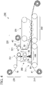
- Fig. 4 represents a conceptual diagram of an SMC manufacturing apparatus that can be preferably used in an SMC manufacturing method of the embodiment.
- an SMC manufacturing apparatus 200 includes a first resin application section 210, a second resin application section 220, a chopping section 230, a deposition section 240, and an impregnation section 250.
- a fragmentation processing apparatus 260 is disposed between the chopping section 230 and the deposition section 240.
- the first resin application section 210 is provided with a first applicator 211 including a doctor blade to form a first resin layer 51 comprising a thermosetting resin composition 50 on a first carrier film 41 drawn out from a roll.
- the second resin application section 220 is provided with a second applicator 221 including a doctor blade to form a second resin layer 52 comprising the same thermosetting resin composition 50 on a second carrier film 42 drawn out from a roll.
- the chopping section 230 is provided with a rotary cutter 231 for chopping a continuous carbon fiber bundle 10 drawn out from a package (the bobbin may be removed).
- the rotary cutter 231 includes a guide roll 232, a pinch roll 233, and a cutter roll 234.
- a plurality of blades 235 are disposed on an outer circumference of the cutter roll 234 at a regular interval in a circumferential direction, and chopped carbon fiber bundles 20 having a constant fiber length can be cut out one after another from the continuous carbon fiber bundle 10.
- a plurality of the continuous carbon fiber bundles 10 are aligned to be parallel to each other in a plane parallel to a rotation axis direction of the rotary cutter 231 and are supplied to the rotary cutter 231 at the same time.
- the rotation axis direction of the rotary cutter 231 is a rotation axis direction of the rolls provided in the rotary cutter 231, that is, a rotation axis direction of the cutter roll 234.
- the directions of the rotation axes of the guide roll 232 and the pinch roll 233 are also the same as the direction of the rotation axis of the cutter roll 234.
- the deposition section 240 is disposed below the chopping section 230.
- the first carrier film 41 is conveyed from the first resin application section 210 to the impregnation section 250 via the deposition section 240.
- the chopped carbon fiber bundles 20 produced in the chopping section 230 are fallen and deposited on the first resin layer 51 formed on a surface of the first carrier film 41, so that a carbon fiber mat 30 is formed.
- a mechanism for gradually bringing the first carrier film 41 and the second carrier film 42 closer to each other is disposed in an upstream part of the impregnation section 250.
- An impregnation machine 251 is disposed in a main part of the impregnation section 250.
- the impregnation machine 251 includes two belt conveyors located above and below, and includes rollers for pressurizing the laminate by sandwiching it together with the conveyor belts.
- the fragmentation processing apparatus 260 disposed between the chopping section 230 and the deposition section 240 includes a cover 261, and guide plates 262 and a pair of pin rollers (first pin roller 263a and second pin roller 263b) which are disposed inside the cover.
- the first pin roller 263a and the second pin roller 263b have substantially the same axial length, and have the rotation axes parallel to each other.
- the fragmentation processing apparatus 260 is disposed such that the rotation axes of the first pin roller 263a and the second pin roller 263b are parallel to the rotation axis direction of the rotary cutter 231.
- the position of the fragmentation processing apparatus 260 is preferably right below the rotary cutter 231.
- the first pin roller 263a has a cylinder 264a, and a plurality of pins 265a having the same shapes and the same dimensions are disposed on the surface thereof.
- Both the cylinder 264a and the pins 265a are rigid bodies, and are formed of metal, for example.
- a diameter of the cylinder 264a is not limited, but can be 60 mm to 150 mm, for example.
- the pins 265a extend to be perpendicular to the rotation axis of the first pin roller 263a.
- the pin 265a has a columnar shape, for example. A boundary between an end surface and a circumferential surface may be chamfered in the pin 265a.
- the diameter of the pin 265a is not limited, but can be, for example, 1 mm to 5 mm.
- the length of the pin 265a that is, the distance from the tip to the root of the pin is not limited, but can be 10 mm to 50 mm, for example.
- the pin 265a has a circular cross section to prevent fuzzing of the chopped carbon fiber bundle 20 processed by the fragmentation processing apparatus 260.
- the pin 265a may have a shape of a cone or a truncated cone whose diameter decreases toward the tip.
- the pin 265a is disposed at each vertex of equilateral triangles (indicated by a broken line) tessellating such that one side is parallel to the axial direction, as represented in Fig. 8 .
- the disposition of the pin 265a represented in Fig. 8 overlaps the original disposition when shifted by 2.5 mm in the axial direction and approximately 4.3 mm in the circumferential direction.
- the maximum radius of the pin roller is defined as a distance from the rotation axis to the tip of the pin.
- the radius of the cylinder 264a is preferably half or more of the maximum radius of the first pin roller 263a, and is more preferably 75% or more. The reason is that as the ratio of the cylinder radius to the maximum radius of the pin roller increases, a difference decreases between the circumferential speed at the tip of the pin and the circumferential speed at the root of the pin when the pin roller is rotated.
- the fragmentation processing apparatus 260 it is preferable that in items as many as possible, including the maximum radius, the cylinder diameter and the shape, the dimension, the number and the disposition of the pins, designs and specifications of the first pin roller 263a and the second pin roller 263b coincide with each other.
- the sum of the maximum radius r M1 of the first pin roller 263a and the maximum radius r M2 of the second pin roller 263b is larger than a distance d 12 between the rotation axes of the two pin rollers.
- the sum of the maximum radius r M1 of the first pin roller 263a and the radius r C2 of the cylinder 264b of the second pin roller is smaller than the distance d 12 between the rotation axes of the two pin rollers.
- the sum of the maximum radius r M2 of the second pin roller 263b and the radius r C1 of the cylinder 264a of the first pin roller is also smaller than the distance d 12 between the rotation axes of the two pin rollers.
- a difference ⁇ (r M1 + r M2 )) - d 12 ⁇ between the sum of the maximum radius r M1 of the first pin roller 263a and the maximum radius r M2 of the second pin roller 263b and the distance d 12 between the rotation axes is not limited but may be 20 mm or less, 15 mm or less, 10 mm or less, or 5 mm or less.
- the first pin roller 263a and the second pin roller 263b are rotationally driven by a drive mechanism (not represented). Rotation speeds of the first pin roller 263a and the second pin roller 263b may be independently controllable.
- Rotation directions of the first pin roller 263a and the second pin roller 263b are as indicated by arrows in Fig. 6 . That is, the first pin roller 263a rotates such that its pins move downward from above on its side facing the second pin roller 263b, and the second pin roller 263b rotates such that its pins move downward from above on its side facing the first pin roller 263a.
- Rotating both the first pin roller 263a and the second pin roller 263b in such a way is advantageous in preventing the chopped carbon fiber bundle 20 from being clogged between the two pin rollers.
- Substantially all of the chopped carbon fiber bundles 20 produced in the chop section 230 are fallen to the deposition section through between the cylinder 264a of the first pin roller 263a and the cylinder 264b of the second pin roller 263b. Since difference in falling positions of the chopped carbon fiber bundles 20 depending on bundle sizes is less likely to occur, even when a distribution of the bundle sizes of the chopped carbon fiber bundles 20 is wide, there is an advantage in that the carbon fiber mat 30 is likely to be uniform in the thickness direction.
- a sum of the maximum radius r M1 of the first pin roller 263a and the maximum radius r M2 of the second pin roller 263b may be equal to the distance d 12 between the rotation axes of the two pin rollers.
- a sum of the maximum radius r M1 of the first pin roller 263a and the maximum radius r M2 of the second pin roller 263b may be slightly smaller than the distance d 12 between the rotation axes of the two pin rollers, and in that case, a difference ⁇ d 12 - (r M1 + r M2 ) ⁇ therebetween is preferably 10 mm or less, and is more preferably 5 mm or less.
- An SMC manufacturing method of the embodiment will be described using, as an example, a case in which the SMC manufacturing apparatus 200 described in 1.2 above is used.
- a continuous carbon fiber bundle is drawn out from a package of the continuous carbon fiber bundle prepared in advance.
- the continuous carbon fiber bundle has a filament number of NK and is partially split into n sub-bundles in advance.
- the continuous carbon fiber bundle may be drawn out by external unwinding from a bobbin package placed on a creel, or the continuous carbon fiber bundle may be drawn out by internal unwinding from a package from which a bobbin is removed.
- the continuous carbon fiber bundle drawn out from the package includes a part in which the sub-bundles are partially overlapped and sticked to each other.
- the drawn out continuous carbon fiber bundle 10 is supplied to the chopping section 230 and cut one after another by the rotary cutter 231, thereby producing the chopped carbon fiber bundles 20 having a predetermined fiber length.
- the produced chopped carbon fiber bundles 20 fall toward the fragmentation processing apparatus 260 placed below the rotary cutter 231.
- the fiber length of the chopped carbon fiber bundle 20 is not limited, but can be 5 to 100 mm, preferably 20 to 60 mm, for example, and can be typically approximately 13 mm, approximately 25 mm, or approximately 50 mm.
- the continuous carbon fiber bundle drawn out from the package includes a part in which the sub-bundles are partially overlapped and sticked to each other.
- the chopped carbon fiber bundles produced in the chopping step include to some extent a fiber bundle having a filament number of more than ⁇ (N/n)+0.5 ⁇ K, which is generated by cutting such part of the continuous carbon fiber bundle.
- the fragmentation processing step aims to improve a distribution of the filament numbers of the chopped carbon fiber bundles in the carbon fiber mat formed in a deposition step (to be described later) by fragmentation of such fiber bundle with the fragmentation processing apparatus.
- the fragmentation processing apparatus 260 At least some of the chopped carbon fiber bundles 20 falling from the rotary cutter 231 come into contact with at least one of the first pin roller 263a and the second pin roller 263b and are divided into a plurality of fragments by an impact.
- the fragmentation processing is not intended for defibration. That is, the fragmentation processing is not to loosen the chopped carbon fiber bundle into single fiber filaments or a state close to single fiber filaments.
- a circumferential speed at a tip of the pin of each of the first pin roller 263a and the second pin roller 263b is set so that the fragmentation processing does not generate a fiber bundle having a filament number of 0.5K or less and a single fiber filament, or even when generated, so that a content thereof in the carbon fiber deposited on the first carrier film 41 is lower than 1% by weight.
- rotation speeds (rpm) of the first pin roller 263a and the second pin roller 263b are set such that the circumferential speed at the tip of the former's pin 265a and the circumferential speed at the tip of the latter's pin 265b are equal to each other.
- the first resin layer 51 comprising the thermosetting resin composition 50 is formed on the first carrier film 41 drawn out from a roll using the first applicator 221, and the second resin layer 52 comprising the same thermosetting resin composition 50 is formed on the second carrier film 42 drawn out from another roll using the second applicator 212.
- the thermosetting resin composition 50 is a fluid paste containing a thermosetting resin as a main component and in which a thickener and a curing agent are blended, and if necessary, additives such as a reactive diluent, a low shrinkage agent, a filler, and a flame retardant are blended.
- thermosetting resin examples include an epoxy resin, a vinyl ester resin, an unsaturated polyester resin, a polyimide resin, a maleimide resin and a phenol resin, and two or more types selected from these resins can be mixed and used.
- thermosetting resins are the epoxy resin, the vinyl ester resin, and the unsaturated polyester resin in view of excellent adhesiveness to the carbon fiber.
- thermosetting resin composition With regard to a specific formulation of the thermosetting resin composition, a related art can be appropriately referred to.
- the chopped carbon fiber bundles 20 processed by the fragmentation processing apparatus 260 fall on the first carrier film 41 conveyed below the fragmentation processing apparatus 260.
- the fallen chopped carbon fiber bundles 20 are deposited on the first resin layer 51 formed on a surface of the first carrier film 41, thereby forming the carbon fiber mat 30.
- the first carrier film 41 loaded with the carbon fiber mat 30 deposited on the first resin layer 51 is laminated with the second carrier film 42 with a side having the second resin layer 52 formed thereon facing downward.
- the carbon fiber mat 30 is impregnated with the thermosetting resin composition 50 by pressurizing the laminate formed by the lamination with the impregnation machine 251.
- the impregnated carbon fiber mat 30 is wound on a bobbin while sandwiched between the first carrier film 41 and the second carrier film 42 and becomes an SMC product through an aging step to be performed when necessary.
- the thermosetting resin composition 50 becomes highly viscous by an action of the added thickener and is brought into a semi-cured state.
- the continuous carbon fiber bundle having a filament number of NK and partially split into n sub-bundles is used as a raw material.
- a continuous carbon fiber bundle which has not been processed to partially split may be used as the raw material.
- An SMC manufacturing method comprising:
- a radius of a cylinder is equal to or larger than half of a maximum radius.
- thermosetting resin composition The manufacturing method according to any one of [36] to [42], wherein the carbon fiber mat is pressurized together with the thermosetting resin composition to impregnate the carbon fiber mat with the thermosetting resin composition.
- thermosetting resin composition is applied to an upper surface of the carrier film before forming the carbon fiber mat by depositing the chopped carbon fiber bundles.
- a flat continuous carbon fiber bundle (TR50S15L manufactured by Mitsubishi Chemical Corporation) having a filament number of 15K, an initial width of 8 mm and a thickness of 0.1 mm was prepared.
- the continuous carbon fiber bundle was partially split into five sub-bundles each having a width of 1.6 mm. Positions of inter-slit gaps along the fiber direction were the same among all of the slit rows.
- a carbon fiber mat was prepared from the continuous carbon fiber bundle having a filament number of 15K and partially split into five sub-bundles prepared in the above-described procedure using an SMC manufacturing apparatus having the same configuration as the SMC manufacturing apparatus represented in Fig. 4 except that the fragmentation processing apparatus was not provided.
- a plurality of the continuous carbon fiber bundles were supplied to a rotary cutter in a state of being aligned in parallel at an equal interval and were cut every 25.4 mm.
- the chopped carbon fiber bundles were fallen onto a carrier film which travels below the rotary cutter at a line speed of 5 m/min and was not coated with a thermosetting resin composition.
- the fallen chopped carbon fiber bundles were deposited on the carrier film to form a carbon fiber mat.
- Fig. 10 represents a distribution of the filament numbers of the chopped carbon fiber bundles in the carbon fiber mat, which was obtained by converting the measured weights into filament numbers.
- a content of the carbon fiber bundle having the filament number of more than 0.5K was 99.9% by weight or more.
- the carbon fiber mat was prepared using the same SMC manufacturing apparatus used in Experiment 1 except that the fragmentation processing apparatus was provided, and the distribution of the filament numbers thereof was measured in the same manner as in Experiment 1.
- the procedure for preparing the carbon fiber mat was the same as that in Experiment 1 except that the chopped carbon fiber bundles were subjected to a fragmentation processing by the fragmentation processing apparatus before being deposited on the carrier film.
- a configuration of the fragmentation processing apparatus was the same as that included in the SMC manufacturing apparatus represented in Fig. 4 .
- Both the two pin rollers were formed of metal and had the same configuration.
- a diameter and a length of a pin disposed on a cylinder circumferential surface were respectively 3 mm and 20 mm.
- the disposition of the pins on the circumferential surface of the cylinder of each pin roller was periodic, and the disposition overlapped the original disposition when shifted by 7.5 mm in the axial direction and 6.5 mm in the circumferential direction.
- the sum of the maximum radii of the two pin rollers was 10 mm larger than the distance between the rotation axes of the two pin rollers.
- the two pin rollers were rotated such that in both pin rollers the circumferential speeds at the pin tips were 377 m/min and in each pin rollers the pins moved downward from above on the side facing the other pin roller.
- Fig. 11 represents the distribution of the filament numbers of the chopped carbon fiber bundles in the prepared carbon fiber mat.
- a content of the carbon fiber bundle having the filament number of more than 0.5K was 99.9% by weight or more.
- the carbon fiber mat was prepared in the same manner as in Experiment 2 except that both the two pin rollers were rotated such that in each pin rollers the pins moved upward from below on the side facing the other pin roller, and the distribution of the filament numbers was measured.
- Fig. 12 represents the distribution of the filament numbers of the chopped carbon fiber bundles in the prepared carbon fiber mat.
- the carbon fiber mat was prepared in the same manner as in Experiment 2 except that the two pin rollers were rotated in the same direction, and the distribution of the filament numbers was measured.
- Fig. 13 represents the distribution of the filament numbers of the chopped carbon fiber bundles in the prepared carbon fiber mat.
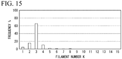
- the carbon fiber mat was prepared in the same manner as in Experiment 2 except that the distance between the rotation axes of the two pin rollers was the same as the sum of the maximum radii of the two pin rollers, and the distribution of the filament numbers was measured.
- Fig. 15 represents the distribution of the filament numbers of the chopped carbon fiber bundles in the prepared carbon fiber mat.
- a square end type fiber package was produced by preparing and partially splitting a flat continuous carbon fiber bundle having the filament number of 15,000 (15K), the initial width of 8 mm and the thickness of 0.1 mm and thereafter, winding the partially split continuous carbon fiber bundle on a paper bobbin having a diameter of 82 mm and a length of 280 mm with a traverse length of 254 mm. Widening with a spreader was not performed.
- a splitter having four rotary blades was used for partially splitting the continuous carbon fiber bundle.
- the continuous carbon fiber bundle was split into five sub-bundles each having the width of 1.6 mm and partially joined to each other. Positions of inter-slit gap in the fiber direction were the same among all of the slit rows.
- the lead angle at the winding start was 9.9°
- the lead angle at the winding end was 5°
- the winding ratio was 11.30
- the winding amount was 5.0 kg.
- the total width of the continuous carbon fiber bundle wound on the bobbin was made to be 6 mm which was 75% of the total sum of the widths of the sub-bundles.
Landscapes
- Engineering & Computer Science (AREA)
- Chemical & Material Sciences (AREA)
- Textile Engineering (AREA)
- Mechanical Engineering (AREA)
- Materials Engineering (AREA)
- Composite Materials (AREA)
- Health & Medical Sciences (AREA)
- Chemical Kinetics & Catalysis (AREA)
- Medicinal Chemistry (AREA)
- Polymers & Plastics (AREA)
- Organic Chemistry (AREA)
- Manufacturing & Machinery (AREA)
- Inorganic Chemistry (AREA)
- Reinforced Plastic Materials (AREA)
Abstract
Description
- The present invention relates to a manufacturing method of an SMC (sheet molding compound), and particularly relates to a manufacturing method of a CF-SMC which is an SMC using carbon fiber (CF).
- Priority is claimed on
Japanese Patent Application No. 2020-047206, filed March 18, 2020 - In recent years, CFRP (carbon fiber reinforced plastic) which is a composite material comprising a carbon fiber and a resin has been widely used for components of aircraft, automobiles, ships and other various transportation equipment, sports goods, and leisure goods.
- A certain type of CFRP products is molded from the CF-SMC by using a compression molding method.
- The CF-SMC is a type of carbon fiber prepregs, and has a structure in which a mat comprising chopped carbon fiber bundles (also referred to as a "chopped carbon fiber tow" or a "chopped carbon fiber strand") is impregnated with a thermosetting resin composition.
- The CFRP has higher strength when being reinforced with a carbon fiber bundle having a smaller filament number. On the other hand, the carbon fiber bundle requires a higher manufacturing cost when having a smaller filament number (smaller tow size) (Patent Document 1).
- It is proposed adding a step of partially splitting a continuous carbon fiber bundle unwound from a creel before chopping to an SMC manufacturing method in which steps are continuously performed from chopping of the continuous carbon fiber bundle to resin impregnation of a carbon fiber mat (Patent Document 2).
-
- [Patent Document 1]
United States Patent Application, Publication No. 2012/0213997 - [Patent Document 2]
PCT International Publication No. WO2017/221655 - It is expected that an SMC which can give a high-strength CFRP molded product can be manufactured at low cost by using a technique of partially splitting before use a continuous carbon fiber bundle having a large filament number, typically such as a large tow.
- Because various adjustments are required in the step of partially splitting the continuous carbon fiber bundle, overall manufacturing efficiency may be improved when the step and subsequent steps are separated in manufacturing the SMC.
- The present invention is made in a process of studies performed by the present inventors, based on the above-described idea, and mainly aims to provide a useful improvement in a CF-SMC manufacturing technique including a CF-SMC manufacturing method in which a continuous carbon fiber bundle is partially split before use.
- In some cases, the present specification may explicitly or implicitly disclose problems which can be solved by each embodiment of the present invention.
- An aspect of the present invention relates to an SMC manufacturing method.
- The SMC manufacturing method according to a preferred embodiment of the present invention includes, but not limited to the followings.
- [1] An SMC manufacturing method comprising:
- (i) drawing out a continuous carbon fiber bundle from a package, the continuous carbon fiber bundle having a filament number of NK and partially split into n sub-bundles in advance;
- (ii) forming chopped carbon fiber bundles by chopping the continuous carbon fiber bundle drawn out from the package with a rotary cutter;
- (iii) forming a carbon fiber mat by depositing the chopped carbon fiber bundles on a carrier film traveling below the rotary cutter; and
- (iv) impregnating the carbon fiber mat with a thermosetting resin composition,
- wherein fragmentation processing using a fragmentation processing apparatus (A) below is performed on the chopped carbon fiber bundles before being deposited on the carrier film,
- the fragmentation processing apparatus (A) comprising a first pin roller and a second pin roller, each of which has a rotation axis parallel to a rotation axis direction of the rotary cutter, and the first pin roller is rotationally driven such that its pins move downward from above on its side facing the second pin roller, and the second pin roller is rotationally driven such that its pins move downward from above on its side facing the first pin roller.
- [2] The manufacturing method according to [1],
wherein a sum of a maximum radius of the first pin roller and a maximum radius of the second pin roller is equal to or larger than a distance between rotation axes of the first pin roller and the second pin roller. - [3] The manufacturing method according to [2],
wherein a sum of a maximum radius of the first pin roller and a maximum radius of the second pin roller is larger than the distance between the rotation axes of the first pin roller and the second pin roller. - [4] The manufacturing method according to [1],
wherein a sum of a maximum radius of the first pin roller and a maximum radius of the second pin roller is smaller than a distance between rotation axes of the first pin roller and the second pin roller, and a difference therebetween is 10 mm or less. - [5] The manufacturing method according to any one of [1] to [4],
wherein in the package, the continuous carbon fiber bundle is wound such that there is no gap between the sub-bundles. - [6] The manufacturing method according to any one of [1] to [5],
wherein in the package, the continuous carbon fiber bundle is wound such that adjacent sub-bundles overlap each other. - [7] The manufacturing method according to any one of [1] to [6],
wherein a total width of the continuous carbon fiber bundle wound in the package is smaller than a total sum of widths of the sub-bundles. - [8] The manufacturing method according to any one of [1] to [7],
wherein N is 15 or more. - [9] The manufacturing method according to any one of [1] to [8],
wherein in each of the first pin roller and the second pin roller, a radius of a cylinder is equal to or larger than half of a maximum radius. - [10] The manufacturing method according to any one of [1] to [9],
wherein a circumferential speed at a pin tip of the first pin roller is equal to a circumferential speed at a pin tip of the second pin roller. - [11] The manufacturing method according to any one of [1] to [10],
wherein a content of a carbon fiber bundle having a filament number of more than 0.5K in the carbon fiber mat is 99% by weight or more. - [12] The manufacturing method according to any one of [1] to [11],
wherein the fragmentation processing reduces a number of the chopped carbon fiber bundles having a filament number of larger than {(N/n) + 0.5} K comprised in a unit weight of the carbon fiber mat. - [13] The manufacturing method according to any one of [1] to [12],
wherein the carbon fiber mat is pressurized together with the thermosetting resin composition to impregnate the carbon fiber mat with the thermosetting resin composition. - [14] The manufacturing method according to any one of [1] to [13],
wherein at least a portion of the thermosetting resin composition is applied to an upper surface of the carrier film before the step (iii).
Another aspect of the present invention relates to a processing method of a carbon fiber bundle. The processing method of a carbon fiber bundle according to a preferred embodiment of the present invention includes the followings, but is not limited thereto. - [15] A processing method of carbon fiber bundles, the method comprising:
- performing fragmentation processing using a fragmentation processing apparatus (A) below on the carbon fiber bundles having fiber lengths of 60 mm or less,
- wherein the fragmentation processing apparatus (A) comprises a first pin roller and a second pin roller which have rotation axes parallel to each other, and the first pin roller is rotationally driven such that its pins move downward from above on its side facing the second pin roller, and the second pin roller is rotationally driven such that its pins move downward from above on its side facing the first pin roller.
- [16] The processing method according to [15],
wherein a sum of a maximum radius of the first pin roller and a maximum radius of the second pin roller is equal to or larger than a distance between rotation axes of the first pin roller and the second pin roller. - [17] The processing method according to [16],
wherein a sum of a maximum radius of the first pin roller and a maximum radius of the second pin roller is larger than the distance between the rotation axes of the first pin roller and the second pin roller. - [18] The processing method according to [15],
wherein a sum of a maximum radius of the first pin roller and a maximum radius of the second pin roller is smaller than a distance between rotation axes of the first pin roller and the second pin roller, and a difference therebetween is 10 mm or less. - [19] The processing method according to any one of [15] to [18],
wherein in each of the first pin roller and the second pin roller, a radius of a cylinder is equal to or larger than half of a maximum radius. - [20] The processing method according to any one of [15] to [19],
wherein a circumferential speed at a pin tip of the first pin roller is equal to a circumferential speed at a pin tip of the second pin roller.
Still another aspect of the present invention relates to a fragmentation processing apparatus for a carbon fiber bundle.
The fragmentation processing apparatus for a carbon fiber bundle according to a preferred embodiment of the present invention includes the followings, but is not limited thereto. - [21] A fragmentation processing apparatus for a carbon fiber bundle, comprising:
- a first pin roller and a second pin roller which have rotation axes parallel to each other,
- wherein the first pin roller can be rotationally driven such that its pins move downward from above on its side facing the second pin roller, and the second pin roller can be rotationally driven such that its pins move downward from above on its side facing the first pin roller.
- [22] The fragmentation processing apparatus according to [21],
wherein a sum of a maximum radius of the first pin roller and a maximum radius of the second pin roller is equal to or larger than a distance between rotation axes of the first pin roller and the second pin roller. - [23] The fragmentation processing apparatus according to [22],
wherein a sum of a maximum radius of the first pin roller and a maximum radius of the second pin roller is larger than the distance between the rotation axes of the first pin roller and the second pin roller. - [24] The fragmentation processing apparatus according to [21],
wherein a sum of a maximum radius of the first pin roller and a maximum radius of the second pin roller is smaller than a distance between rotation axes of the first pin roller and the second pin roller, and a difference therebetween is 10 mm or less. - [25] The fragmentation processing apparatus according to any one of [21] to [24],
wherein in each of the first pin roller and the second pin roller, a radius of a cylinder is equal to or larger than half of a maximum radius.
Still another aspect of the present invention relates to a use of a fragmentation processing apparatus.
The use of a fragmentation processing apparatus according to a preferred embodiment of the present invention includes, but not limited to the followings. - [26] Use of a fragmentation processing apparatus below in an SMC manufacturing method comprising forming a carbon fiber mat by depositing chopped carbon fiber bundles on a carrier film, and impregnating the carbon fiber mat with a thermosetting resin composition, wherein a fragmentation processing is performed on the chopped carbon fiber bundles before being deposited on the carrier film,
the fragmentation processing apparatus comprising a first pin roller and a second pin roller which have rotation axes parallel to each other, and the first pin roller can be rotationally driven such that its pins move downward from above on its side facing the second pin roller, and the second pin roller can be rotationally driven such that its pins move downward from above on its side facing the first pin roller. - [27] The use according to [26],
wherein a sum of a maximum radius of the first pin roller and a maximum radius of the second pin roller is equal to or larger than a distance between rotation axes of the first pin roller and the second pin roller. - [28] The use according to [27],
wherein a sum of a maximum radius of the first pin roller and a maximum radius of the second pin roller is larger than the distance between the rotation axes of the first pin roller and the second pin roller. - [29] The use according to [26],
wherein a sum of a maximum radius of the first pin roller and a maximum radius of the second pin roller is smaller than a distance between rotation axes of the first pin roller and the second pin roller, and a difference therebetween is 10 mm or less. - [30] The use according to any one of [26] to [29],
wherein in each of the first pin roller and the second pin roller, a radius of a cylinder is equal to or larger than half of a maximum radius. - [31] Use of a fragmentation processing apparatus in a fragmentation processing of carbon fiber bundles having fiber lengths of 60 mm or less,
wherein the fragmentation processing apparatus comprises a first pin roller and a second pin roller which have rotation axes parallel to each other, and the first pin roller can be rotationally driven such that its pins move downward from above on its side facing the second pin roller, and the second pin roller can be rotationally driven such that its pins move downward from above on its side facing the first pin roller. - [32] The use according to [31],
wherein a sum of a maximum radius of the first pin roller and a maximum radius of the second pin roller is equal to or larger than a distance between rotation axes of the first pin roller and the second pin roller. - [33] The use according to [32],
wherein a sum of a maximum radius of the first pin roller and a maximum radius of the second pin roller is larger than the distance between the rotation axes of the first pin roller and the second pin roller. - [34] The use according to [31],
wherein a sum of a maximum radius of the first pin roller and a maximum radius of the second pin roller is smaller than a distance between rotation axes of the first pin roller and the second pin roller, and a difference therebetween is 10 mm or less. - [35] The use according to any one of [31] to [34],
wherein in each of the first pin roller and the second pin roller, a radius of a cylinder is equal to or larger than half of a maximum radius. - According to the present invention, there is provided a useful improvement in a CF-SMC manufacturing technique including an SMC manufacturing method in which a continuous carbon fiber is partially split before use.
-
-
Fig. 1 is a schematic diagram of a fiber package manufacturing apparatus. -
Fig. 2A is a plan view of a continuous carbon fiber bundle immediately after being partially split into five parts viewed from a thickness direction. -
Fig. 2B is a sectional view of the continuous carbon fiber bundle immediately after being partially split into five parts representing a cross section perpendicular to a fiber direction. -
Fig. 3 is a schematic diagram representing a cross section perpendicular to the fiber direction of a continuous carbon fiber bundle wound on a bobbin after being partially split into five parts. -
Fig. 4 is a schematic diagram of an SMC manufacturing apparatus. -
Fig. 5 is a schematic diagram of a rotary cutter. -
Fig. 6 is a schematic diagram of a fragmentation processing apparatus. -
Fig. 7 is a schematic diagram of a pin roller provided in the fragmentation processing apparatus. -
Fig. 8 represents a part of a plane-development of a cylinder circumferential surface of a pin roller. -
Fig. 9 is a schematic diagram representing a positional relationship and the like between two pin rollers provided in a fragmentation processing apparatus. -
Fig. 10 is a histogram representing a distribution of filament numbers of chopped carbon fiber bundles in a carbon fiber mat. -
Fig. 11 is a histogram representing a distribution of filament numbers of chopped carbon fiber bundles in a carbon fiber mat. -
Fig. 12 is a histogram representing a distribution of filament numbers of chopped carbon fiber bundles in a carbon fiber mat. -
Fig. 13 is a histogram representing a distribution of filament numbers of chopped carbon fiber bundles in a carbon fiber mat. -
Fig. 14 is a plan view representing a continuous carbon fiber bundle immediately after being partially split into five parts when viewed from the thickness direction. -
Fig. 15 is a histogram representing a distribution of filament numbers of chopped carbon fiber bundles in a carbon fiber mat. - An SMC is a sheet-shaped carbon fiber prepreg obtainable by impregnating a carbon fiber mat comprising a chopped carbon fiber bundle with a thermosetting resin composition.
- One embodiment of the present invention is an SMC manufacturing method including the following steps (i) to (iv).
- (i) A step of drawing out a continuous carbon fiber bundle from a package, the continuous fiber bundle having a filament number of NK and partially split into n sub-bundles in advance.
- (ii) A step of chopping the continuous carbon fiber bundle drawn out from the package with a rotary cutter to form chopped carbon fiber bundles.
- (iii) A step of depositing the chopped carbon fiber bundles on a carrier film traveling below the rotary cutter to form a carbon fiber mat.
- (iv) A step of impregnating the carbon fiber mat with a thermosetting resin composition.
- In the SMC manufacturing method of the embodiment, fragmentation processing is performed so that at least some of the chopped carbon fiber bundles before being deposited on the carrier film is fragmented by being brought into contact with a rotating body. Through the fragmentation processing, a distribution of the filament numbers of the chopped carbon fiber bundles included in the carbon fiber mat formed in the step (iii) above becomes different from that when the fragmentation processing is not performed.
- When necessary, a step of thickening the thermosetting resin composition is further provided after the step (iv).
- In the SMC manufacturing method of the embodiment, a package of the continuous carbon fiber bundle prepared in advance is used. The continuous carbon fiber bundle has a filament number of NK and is partially split into n sub-bundles.
- NK means N×1000. For example, a filament number of a carbon fiber bundle comprising 3,000 single filaments is 3K, and a filament number of a carbon fiber bundle comprising 12,000 single filaments is 12K.
- N is usually 12 or more, preferably 15 or more, and can be, but not limited to 18, 24, 36, 48, or 50, for example.
- When it is said that a continuous carbon fiber bundle is partially split into n sub-bundles, it means, in other words, that the continuous carbon fiber bundle is partially divided into n parts. Each of the n fiber bundles formed by dividing into n parts is called a sub-bundle.
- The package of the partially split continuous carbon fiber bundle can be manufactured using, but not limited to a fiber package manufacturing apparatus represented in a conceptual diagram in
Fig. 1 . - Referring to
Fig. 1 , a fiberpackage manufacturing apparatus 100 includes aspread section 110, asplit section 120, and a windingsection 130. - A continuous
carbon fiber bundle 10 serving as a starting material and having a filament number of NK is drawn out from a supply bobbin B1. - The continuous
carbon fiber bundle 10 drawn out from the supply bobbin B1 before being split is first spread in thespread section 110. - A
spreader bar 111 provided in thespread section 110 may be heated and may be caused to reciprocate in a width direction of the continuouscarbon fiber bundle 10. Mechanisms therefor can refer to a known technique. - While the continuous
carbon fiber bundle 10 originally has a flat shape, it is further increased in width and further decreased in thickness by being rubbed against thespreader bar 111. The thickness of the continuouscarbon fiber bundle 10 after passing through thespread section 110 is not limited, but can typically be 0.05 to 0.2 mm. - The
spread section 110 may be omitted, when the continuouscarbon fiber bundle 10 is sufficiently flat at a stage when the continuouscarbon fiber bundle 10 is supplied from the supply bobbin B1. For example, a carbon fiber bundle having a bundle width of 50 times or more of an average thickness can be said to be sufficiently flat. - Next, the continuous
carbon fiber bundle 10 is fed to thesplit section 120 and is partially split there. - The
split section 120 is provided with arotary blade 121 for forming a slit in the continuouscarbon fiber bundle 10 and a plurality of godet rolls 123 for controlling a traveling speed of the continuouscarbon fiber bundle 10. - A rotation axis of the
rotary blade 121 is parallel to a width direction of the continuouscarbon fiber bundle 10 traveling along a fiber direction. A plurality ofblade parts 122 are provided at a regular interval in a circumferential direction on an outer circumference of therotary blade 121, so that slits having a constant length are intermittently formed at a regular interval along the fiber direction of the continuouscarbon fiber bundle 10. A slit length and a gap length between the slits can be controlled by adjusting the traveling speed of the continuouscarbon fiber bundle 10, a circumferential speed of therotary blade 121, and/or an interval between theblade portions 122. - The continuous
carbon fiber bundle 10 is partially divided into n parts due to intermittent formation of slits along the fiber direction by (n-1)-number of therotary blades 121 aligned in a direction parallel to the width direction of the traveling continuouscarbon fiber bundle 10. - The number n is not limited to, but preferably 3 or more and more preferably 5 or more and may be 10 or more.
- As an example,
Figs. 2A and2B represent the continuouscarbon fiber bundle 10 immediately after the slits extending in the fiber direction are intermittently formed by fourrotary blades 121. - For convenience, when in the continuous
carbon fiber bundle 10, the fiber direction (longitudinal direction) is defined as an x-direction, the width direction is defined as a y-direction and the thickness direction is defined as a z-direction,Fig. 2A is a plan view when the continuouscarbon fiber bundle 10 is viewed from the z-direction andFig. 2B represents a cross section of the continuouscarbon fiber bundle 10 perpendicular to the x-direction (cross section when cut by an yz-plane). - As represented in
Fig. 2A , in the continuouscarbon fiber bundle 10, four slit rows including a first slit row AS1, a second slit row AS2, a third slit row AS3, and a fourth slit row AS4 are formed. - The first slit row AS1 comprises a plurality of first slits S1 aligned in the x-direction.
- The second slit row AS2 comprises a plurality of second slits S2 aligned in the x-direction.
- The third slit row AS3 comprises a plurality of third slits S3 aligned in the x-direction.
- The fourth slit row AS4 comprises a plurality of fourth slits S4 aligned in the x-direction.
- The four slit rows are formed by different rotary blades and therefore are different from each other in positions in the y-direction.
- A slit length Ls and an inter-slit gap length LG are constant in any of the slit rows, and are common also among different slit rows.
- A ratio LS/(LS+LG) of the slit length LS to a sum of the slit length LS and the inter-slit gap length LG is usually 90% or higher and preferably 95% or higher and may be 99% for example. Therefore, as represented in
Fig. 2B , the continuouscarbon fiber bundle 10 is split into fivesub-bundles 11 in most parts. - The positions of the first slit row AS1, the second slit row AS2, the third slit row AS3, and the fourth slit row AS4 in the y-direction are set so that the widths of the five
sub-bundles 11 are approximately the same. For example, when the filament number of the continuouscarbon fiber bundle 10 is 15K, the filament number of each of the sub-bundles 11 is 3K±0.5K. - The slit length Ls is not limited to, but preferably more than 25 mm, more preferably more than 50 mm, and much more preferably more than 500 mm. The slit length Ls can be 10 times or more, further 20 times or more, and further 30 times or more the cutting length when the continuous
carbon fiber bundle 10 is cut to manufacture an SMC. - For example, the slit length Ls can be more than 25 mm and 50 mm or less, more than 50 mm and 100 mm or less, more than 100 mm and 200 mm or less, more than 200 mm and 500 mm or less, more than 500 mm and 1000 mm or less, more than 1000 mm and 1500 mm or less, more than 1500 mm and 2000 mm or less, and more than 2000 mm and 3000 mm or less.
- The inter-slit gap length LG is not limited to, but for example 5 to 10 mm and may be less than 5 mm.
- In an example represented in
Fig. 2A , positions of inter-slit gaps Gs are shifted in the x-direction between the first slit row AS1 and the second slit row AS2. The same applies to between the second slit row AS2 and the third slit row AS3, and between the third slit row AS3 and the fourth slit row AS4. - Such a configuration with a shifting in the positions of the inter-slit gaps Gs in the x- direction between the adjacent slit rows is not essential. In one example, the positions of the inter-slit gaps Gs may be aligned among all of the slit rows as represented in
Fig. 14 . In another example, the positions of the inter-slit gaps Gs may be aligned among some of the slit rows and shifted in the x-direction among some other slit rows. - The slit length Ls, the inter-slit gap length LG, a ratio LS/(LS+LG) of the slit length Ls to a sum of the slit length Ls and the inter-slit gap length LG, and the position of the inter-slit gap GS as described above are not limited to a case where the continuous
carbon fiber bundle 10 is partially split into the five sub-bundles, and the same applies to a case where the continuouscarbon fiber bundle 10 is partially split into four sub-bundles or less or six sub-bundles or more. - Regardless of the number n, the filament number of the sub-bundle formed by splitting the continuous
carbon fiber bundle 10 is preferably 5K or less, more preferably 4K or less, and much more preferably 3K or less. - Regardless of the number n, the filament number of the sub-bundle formed by splitting the continuous
carbon fiber bundle 10 is preferably more than 0.5K and more preferably 1K or more. When the filament number is more than 0.5K, straightness of the carbon fiber bundle is likely to be maintained, and a reinforcing effect tends to be relatively high. - The abovementioned upper limits and lower limits can be arbitrarily combined. For example, regardless of the number n, the filament number of the sub-bundle formed by splitting the continuous
carbon fiber bundle 10 is preferably 0.5K to 5K, more preferably 0.5K to 4K and much more preferably 1K to 3K. - Referring to
Fig. 1 again, the continuouscarbon fiber bundle 10 partially split into n parts in thesplit section 120 is fed to the windingsection 130, and is wound on a winding bobbin B2, thereby completing the package. - For example, the winding bobbin B2 is a paper tube, but is not limited thereto. When the package is used, the winding bobbin B2 can be pulled out, and the continuous carbon fiber bundle can be unwound by internal unwinding.
- The continuous
carbon fiber bundle 10 is wound such that there is no gap between the sub-bundles 11. The reason is to prevent the sub-bundles 11 from biting each other between a part previously wound on the bobbin B2 and a part wound later so as to overlap the previously wound part. By winding such that there is no gap between the sub-bundles 11, the continuouscarbon fiber bundle 10 can be prevented from being entangled or broken during unwinding by external unwinding or internal unwinding. - In order to wind the continuous
carbon fiber bundle 10 on the bobbin so that there is no gap between the sub-bundles 11, a total width W of the continuouscarbon fiber bundle 10 may be made narrower than a sum of sub-bundle widths Ws as represented inFig. 3 . -
Fig. 3 is a sectional view when the continuouscarbon fiber bundle 10 is cut perpendicular to the fiber direction, showing that the fivesub-bundles 11 are arranged side by side without any gap in the y-direction. That is, there is no part where the adjacent sub-bundles 11 are away from each other, and each of the sub-bundles 11 overlaps the immediately adjacent sub-bundle 11 at an edge portion. - The width of the carbon fiber bundle can be reduced by guiding the carbon fiber bundle with a guide having a width narrower than that of the carbon fiber bundle. Therefore, in order to wind the continuous
carbon fiber bundle 10 on the bobbin B2 in a state where the total width W is narrowed than a total sum of the sub-bundle widths Ws, for example, a grooved roll having a groove width narrower than the total sum of the sub-bundle widths may be used in guiding the continuous carbon fiber bundle after being partially split to the winding bobbin. Alternatively, the width of a fiber bundle guide of a traverse device may be narrowed than the total sum of the sub-bundle widths. - When the total width of the continuous carbon fiber bundle is narrowed by the above-described method, not only the sub-bundles may overlap each other, but also some sub-bundles may be folded in the width direction. Therefore, a manner of overlapping of the sub-bundles in the continuous carbon fiber bundle wound on the winding bobbin is not limited to the manner represented in
Fig. 3 and can be various. - In order to ensure that there is no gap between the sub-bundles, the total width of the continuous
carbon fiber bundles 10 when wound on the winding bobbin is preferably 90% or less, more preferably 80% or less of the total sum of the widths of the sub-bundles. - The total width of the continuous carbon fiber bundle when wound on the winding bobbin is preferably, but without limitation, not narrowed until the total width is equal to the width of the sub-bundle. In particular, in a case where the number n of sub-bundles is large, when the total width is excessively small, winding collapse is likely to occur.
- A traverse device (not represented) is usually installed in the winding
section 130. - When the continuous
carbon fiber bundle 10 is traverse-wound on the winding bobbin B2, although not limiting, a lead angle at a start of winding can be set to, for example, 5° to 30° and the lead angle at an end of winding can be set to, for example, 2° to 17°. - A winding ratio represents rotation times of the bobbin during one round trip of a traverse guide, and in other words, the winding ratio may be paraphrased as the number of turns per one traverse cycle. When a yarn is wound on a bobbin with a constant winding ratio, when the winding ratio is an integer, the yarn is wound at the same position of the bobbin in all traverse cycles, thereby causing so-called ribbon winding and a possible poor unwinding property.
- When a fraction of the winding ratio after a decimal point is a multiple of 1/p (p is an integer of 2 or more), the yarn is wound at the same position of the bobbin every p-traverse cycle, thereby causing a possible poor unwinding property particularly when p is small, as in a case where the winding ratio is an integer.
- Therefore, when the continuous
carbon fiber bundle 10 is wound on the winding bobbin B2, the winding ratio is usually not an integer, and further it is preferable that the fraction of the winding ratio after the decimal point is a multiple of none of 1/2, 1/3, 1/4 and 1/5. -
Fig. 4 represents a conceptual diagram of an SMC manufacturing apparatus that can be preferably used in an SMC manufacturing method of the embodiment. - Referring to
Fig. 4 , anSMC manufacturing apparatus 200 includes a firstresin application section 210, a secondresin application section 220, achopping section 230, adeposition section 240, and animpregnation section 250. Afragmentation processing apparatus 260 is disposed between thechopping section 230 and thedeposition section 240. - The first
resin application section 210 is provided with afirst applicator 211 including a doctor blade to form afirst resin layer 51 comprising athermosetting resin composition 50 on afirst carrier film 41 drawn out from a roll. - The second
resin application section 220 is provided with asecond applicator 221 including a doctor blade to form asecond resin layer 52 comprising the samethermosetting resin composition 50 on asecond carrier film 42 drawn out from a roll. - The
chopping section 230 is provided with arotary cutter 231 for chopping a continuouscarbon fiber bundle 10 drawn out from a package (the bobbin may be removed). - As represented in
Fig. 5 , therotary cutter 231 includes aguide roll 232, apinch roll 233, and acutter roll 234. A plurality ofblades 235 are disposed on an outer circumference of thecutter roll 234 at a regular interval in a circumferential direction, and choppedcarbon fiber bundles 20 having a constant fiber length can be cut out one after another from the continuouscarbon fiber bundle 10. - Usually, a plurality of the continuous
carbon fiber bundles 10 are aligned to be parallel to each other in a plane parallel to a rotation axis direction of therotary cutter 231 and are supplied to therotary cutter 231 at the same time. - The rotation axis direction of the
rotary cutter 231 is a rotation axis direction of the rolls provided in therotary cutter 231, that is, a rotation axis direction of thecutter roll 234. The directions of the rotation axes of theguide roll 232 and thepinch roll 233 are also the same as the direction of the rotation axis of thecutter roll 234. - The
deposition section 240 is disposed below thechopping section 230. Thefirst carrier film 41 is conveyed from the firstresin application section 210 to theimpregnation section 250 via thedeposition section 240. When thefirst carrier film 41 travels in thedeposition section 240, the chopped carbon fiber bundles 20 produced in thechopping section 230 are fallen and deposited on thefirst resin layer 51 formed on a surface of thefirst carrier film 41, so that acarbon fiber mat 30 is formed. - A mechanism for gradually bringing the
first carrier film 41 and thesecond carrier film 42 closer to each other is disposed in an upstream part of theimpregnation section 250. Animpregnation machine 251 is disposed in a main part of theimpregnation section 250. In order that a laminate in which thecarbon fiber mat 30 and thethermosetting resin composition 50 are sandwiched between thefirst carrier film 41 and thesecond carrier film 42 is conveyed by being sandwiched from above and below with two conveyor belts, theimpregnation machine 251 includes two belt conveyors located above and below, and includes rollers for pressurizing the laminate by sandwiching it together with the conveyor belts. - As represented in
Fig. 6 , thefragmentation processing apparatus 260 disposed between thechopping section 230 and thedeposition section 240 includes acover 261, and guideplates 262 and a pair of pin rollers (first pin roller 263a andsecond pin roller 263b) which are disposed inside the cover. Thefirst pin roller 263a and thesecond pin roller 263b have substantially the same axial length, and have the rotation axes parallel to each other. - In the
SMC manufacturing apparatus 200, thefragmentation processing apparatus 260 is disposed such that the rotation axes of thefirst pin roller 263a and thesecond pin roller 263b are parallel to the rotation axis direction of therotary cutter 231. The position of thefragmentation processing apparatus 260 is preferably right below therotary cutter 231. - Referring to
Fig. 7 , thefirst pin roller 263a has acylinder 264a, and a plurality ofpins 265a having the same shapes and the same dimensions are disposed on the surface thereof. Both thecylinder 264a and thepins 265a are rigid bodies, and are formed of metal, for example. - A diameter of the
cylinder 264a is not limited, but can be 60 mm to 150 mm, for example. - The
pins 265a extend to be perpendicular to the rotation axis of thefirst pin roller 263a. Although not limited, thepin 265a has a columnar shape, for example. A boundary between an end surface and a circumferential surface may be chamfered in thepin 265a. - The diameter of the
pin 265a is not limited, but can be, for example, 1 mm to 5 mm. - The length of the
pin 265a, that is, the distance from the tip to the root of the pin is not limited, but can be 10 mm to 50 mm, for example. - It is preferable that the
pin 265a has a circular cross section to prevent fuzzing of the choppedcarbon fiber bundle 20 processed by thefragmentation processing apparatus 260. Thepin 265a may have a shape of a cone or a truncated cone whose diameter decreases toward the tip. - It is preferable that disposition of the
pin 265a on the circumferential surface of thecylinder 264a overlaps original disposition when shifted by 5 mm to 20 mm in the axial direction and 4 mm to 30 mm in the circumferential direction. - For example, in a case of the
cylinder 264a represented inFig. 7 , when the circumferential surface is plane-developed, thepin 265a is disposed at each vertex of equilateral triangles (indicated by a broken line) tessellating such that one side is parallel to the axial direction, as represented inFig. 8 . For example, when the length of one side of the equilateral triangle is 5 mm, the disposition of thepin 265a represented inFig. 8 overlaps the original disposition when shifted by 2.5 mm in the axial direction and approximately 4.3 mm in the circumferential direction. - In this specification, the maximum radius of the pin roller is defined as a distance from the rotation axis to the tip of the pin. In the
first pin roller 263a, the radius of thecylinder 264a is preferably half or more of the maximum radius of thefirst pin roller 263a, and is more preferably 75% or more. The reason is that as the ratio of the cylinder radius to the maximum radius of the pin roller increases, a difference decreases between the circumferential speed at the tip of the pin and the circumferential speed at the root of the pin when the pin roller is rotated. - All with regard to the
first pin roller 263a described above are also applied to thesecond pin roller 263b. - Although not limited, in order to reduce costs for designing, manufacturing, and maintaining the
fragmentation processing apparatus 260, it is preferable that in items as many as possible, including the maximum radius, the cylinder diameter and the shape, the dimension, the number and the disposition of the pins, designs and specifications of thefirst pin roller 263a and thesecond pin roller 263b coincide with each other. - Referring to
Fig. 9 , in thefragmentation processing apparatus 260, the sum of the maximum radius rM1 of thefirst pin roller 263a and the maximum radius rM2 of thesecond pin roller 263b is larger than a distance d12 between the rotation axes of the two pin rollers. - The sum of the maximum radius rM1 of the
first pin roller 263a and the radius rC2 of thecylinder 264b of the second pin roller is smaller than the distance d12 between the rotation axes of the two pin rollers. Similarly, the sum of the maximum radius rM2 of thesecond pin roller 263b and the radius rC1 of thecylinder 264a of the first pin roller is also smaller than the distance d12 between the rotation axes of the two pin rollers. - A difference {(rM1 + rM2)) - d12} between the sum of the maximum radius rM1 of the
first pin roller 263a and the maximum radius rM2 of thesecond pin roller 263b and the distance d12 between the rotation axes is not limited but may be 20 mm or less, 15 mm or less, 10 mm or less, or 5 mm or less. - The
first pin roller 263a and thesecond pin roller 263b are rotationally driven by a drive mechanism (not represented). Rotation speeds of thefirst pin roller 263a and thesecond pin roller 263b may be independently controllable. - Rotation directions of the
first pin roller 263a and thesecond pin roller 263b are as indicated by arrows inFig. 6 . That is, thefirst pin roller 263a rotates such that its pins move downward from above on its side facing thesecond pin roller 263b, and thesecond pin roller 263b rotates such that its pins move downward from above on its side facing thefirst pin roller 263a. - Rotating both the
first pin roller 263a and thesecond pin roller 263b in such a way is advantageous in preventing the choppedcarbon fiber bundle 20 from being clogged between the two pin rollers. - Substantially all of the chopped carbon fiber bundles 20 produced in the
chop section 230 are fallen to the deposition section through between thecylinder 264a of thefirst pin roller 263a and thecylinder 264b of thesecond pin roller 263b. Since difference in falling positions of the choppedcarbon fiber bundles 20 depending on bundle sizes is less likely to occur, even when a distribution of the bundle sizes of the chopped carbon fiber bundles 20 is wide, there is an advantage in that thecarbon fiber mat 30 is likely to be uniform in the thickness direction. - In a modified embodiment, in the
fragmentation processing apparatus 260, a sum of the maximum radius rM1 of thefirst pin roller 263a and the maximum radius rM2 of thesecond pin roller 263b may be equal to the distance d12 between the rotation axes of the two pin rollers. - In another modified embodiment, in the
fragmentation processing apparatus 260, a sum of the maximum radius rM1 of thefirst pin roller 263a and the maximum radius rM2 of thesecond pin roller 263b may be slightly smaller than the distance d12 between the rotation axes of the two pin rollers, and in that case, a difference {d12 - (rM1 + rM2)} therebetween is preferably 10 mm or less, and is more preferably 5 mm or less. - An SMC manufacturing method of the embodiment will be described using, as an example, a case in which the
SMC manufacturing apparatus 200 described in 1.2 above is used. - In a drawing out step, a continuous carbon fiber bundle is drawn out from a package of the continuous carbon fiber bundle prepared in advance. The continuous carbon fiber bundle has a filament number of NK and is partially split into n sub-bundles in advance.
- In this step, the continuous carbon fiber bundle may be drawn out by external unwinding from a bobbin package placed on a creel, or the continuous carbon fiber bundle may be drawn out by internal unwinding from a package from which a bobbin is removed.
- As described above, when the package is manufactured, the continuous carbon fiber bundle is wound on the bobbin in a state where the adjacent sub-bundles overlap each other. Therefore, the continuous carbon fiber bundle drawn out from the package includes a part in which the sub-bundles are partially overlapped and sticked to each other.
- In a chopping step, the drawn out continuous
carbon fiber bundle 10 is supplied to thechopping section 230 and cut one after another by therotary cutter 231, thereby producing the choppedcarbon fiber bundles 20 having a predetermined fiber length. The produced choppedcarbon fiber bundles 20 fall toward thefragmentation processing apparatus 260 placed below therotary cutter 231. - The fiber length of the chopped
carbon fiber bundle 20 is not limited, but can be 5 to 100 mm, preferably 20 to 60 mm, for example, and can be typically approximately 13 mm, approximately 25 mm, or approximately 50 mm. - As described above, the continuous carbon fiber bundle drawn out from the package includes a part in which the sub-bundles are partially overlapped and sticked to each other. The chopped carbon fiber bundles produced in the chopping step include to some extent a fiber bundle having a filament number of more than { (N/n)+0.5 } K, which is generated by cutting such part of the continuous carbon fiber bundle. The fragmentation processing step aims to improve a distribution of the filament numbers of the chopped carbon fiber bundles in the carbon fiber mat formed in a deposition step (to be described later) by fragmentation of such fiber bundle with the fragmentation processing apparatus.
- In the
fragmentation processing apparatus 260, at least some of the choppedcarbon fiber bundles 20 falling from therotary cutter 231 come into contact with at least one of thefirst pin roller 263a and thesecond pin roller 263b and are divided into a plurality of fragments by an impact. - The fragmentation processing is not intended for defibration. That is, the fragmentation processing is not to loosen the chopped carbon fiber bundle into single fiber filaments or a state close to single fiber filaments. In a preferred example, a circumferential speed at a tip of the pin of each of the
first pin roller 263a and thesecond pin roller 263b is set so that the fragmentation processing does not generate a fiber bundle having a filament number of 0.5K or less and a single fiber filament, or even when generated, so that a content thereof in the carbon fiber deposited on thefirst carrier film 41 is lower than 1% by weight. - One of reasons why the rotation directions of the
first pin roller 263a and thesecond pin roller 263b are each set such that the pins move downward from above on the side facing the other pin roller is to prevent applying a strong shearing force to the choppedcarbon fiber bundles 20 passing through between the two pin rollers. It is conceivable that the strong shearing force causes fuzzing or straightness deterioration of the carbon fiber bundles. - In order to more effectively achieve this object, it is preferable that rotation speeds (rpm) of the
first pin roller 263a and thesecond pin roller 263b are set such that the circumferential speed at the tip of the former'spin 265a and the circumferential speed at the tip of the latter'spin 265b are equal to each other. - In a resin application step, the
first resin layer 51 comprising thethermosetting resin composition 50 is formed on thefirst carrier film 41 drawn out from a roll using thefirst applicator 221, and thesecond resin layer 52 comprising the samethermosetting resin composition 50 is formed on thesecond carrier film 42 drawn out from another roll using the second applicator 212. - The
thermosetting resin composition 50 is a fluid paste containing a thermosetting resin as a main component and in which a thickener and a curing agent are blended, and if necessary, additives such as a reactive diluent, a low shrinkage agent, a filler, and a flame retardant are blended. - Typical examples of the thermosetting resin are an epoxy resin, a vinyl ester resin, an unsaturated polyester resin, a polyimide resin, a maleimide resin and a phenol resin, and two or more types selected from these resins can be mixed and used.
- Preferred thermosetting resins are the epoxy resin, the vinyl ester resin, and the unsaturated polyester resin in view of excellent adhesiveness to the carbon fiber.
- With regard to a specific formulation of the thermosetting resin composition, a related art can be appropriately referred to.
- In a deposition step, the chopped
carbon fiber bundles 20 processed by thefragmentation processing apparatus 260 fall on thefirst carrier film 41 conveyed below thefragmentation processing apparatus 260. The fallen choppedcarbon fiber bundles 20 are deposited on thefirst resin layer 51 formed on a surface of thefirst carrier film 41, thereby forming thecarbon fiber mat 30. - On the way to the
impregnation machine 251, thefirst carrier film 41 loaded with thecarbon fiber mat 30 deposited on thefirst resin layer 51 is laminated with thesecond carrier film 42 with a side having thesecond resin layer 52 formed thereon facing downward. - The
carbon fiber mat 30 is impregnated with thethermosetting resin composition 50 by pressurizing the laminate formed by the lamination with theimpregnation machine 251. - After the impregnation step is completed, the impregnated
carbon fiber mat 30 is wound on a bobbin while sandwiched between thefirst carrier film 41 and thesecond carrier film 42 and becomes an SMC product through an aging step to be performed when necessary. In the aging step, thethermosetting resin composition 50 becomes highly viscous by an action of the added thickener and is brought into a semi-cured state. - According to the SMC manufacturing method described in 1.3, the continuous carbon fiber bundle having a filament number of NK and partially split into n sub-bundles is used as a raw material. In the SMC manufacturing method according to a modified embodiment, a continuous carbon fiber bundle which has not been processed to partially split may be used as the raw material.
- Therefore, the SMC manufacturing method below is also included in the embodiment of the present invention.
- An SMC manufacturing method comprising:
- forming chopped carbon fiber bundles by chopping a continuous carbon fiber bundle with a rotary cutter;
- forming a carbon fiber mat by depositing the chopped carbon fiber bundles on a carrier film traveling below the rotary cutter; and
- impregnating the carbon fiber mat with a thermosetting resin composition,
- wherein fragmentation processing using a fragmentation processing apparatus (A) below is performed on the chopped carbon fiber bundles before being deposited on the carrier film,
- the fragmentation processing apparatus (A) comprises a first pin roller and a second pin roller, each of which has a rotation axis parallel to a rotation axis direction of the rotary cutter, and the first pin roller is rotationally driven such that its pins move downward from above on its side facing the second pin roller, and the second pin roller is rotationally driven such that its pins move downward from above on its side facing the first pin roller.
- The manufacturing method according to [36],
wherein a sum of a maximum radius of the first pin roller and a maximum radius of the second pin roller is equal to or larger than a distance between rotation axes of the first pin roller and the second pin roller. - The manufacturing method according to [37],
wherein the sum of the maximum radius of the first pin roller and the maximum radius of the second pin roller is larger than the distance between the rotation axes of the first pin roller and the second pin roller. - The manufacturing method according to [36],
wherein a sum of a maximum radius of the first pin roller and a maximum radius of the second pin roller is smaller than a distance between rotation axes of the first pin roller and the second pin roller, and a difference therebetween is 10 mm or less. - The manufacturing method according to any one of [36] to [39],
wherein in each of the first pin roller and the second pin roller, a radius of a cylinder is equal to or larger than half of a maximum radius. - The manufacturing method according to any one of [36] to [40],
wherein a circumferential speed at a pin tip of the first pin roller is equal to a circumferential speed at a pin tip of the second pin roller. - The manufacturing method according to any one of [36] to [41],
wherein a content of a carbon fiber bundle having a filament number of more than 0.5K in the carbon fiber mat is 99% by weight or more. - The manufacturing method according to any one of [36] to [42],
wherein the carbon fiber mat is pressurized together with the thermosetting resin composition to impregnate the carbon fiber mat with the thermosetting resin composition. - The manufacturing method according to any one of [36] to [43],
wherein at least a part of the thermosetting resin composition is applied to an upper surface of the carrier film before forming the carbon fiber mat by depositing the chopped carbon fiber bundles. - Hereinafter, results of experiments performed by the present inventors will be described.
- As a starting material, a flat continuous carbon fiber bundle (TR50S15L manufactured by Mitsubishi Chemical Corporation) having a filament number of 15K, an initial width of 8 mm and a thickness of 0.1 mm was prepared. By forming four slit rows each having a slit length of 1,000 mm and an inter-slit gap length of 5 mm using a splitter having four rotary blades, the continuous carbon fiber bundle was partially split into five sub-bundles each having a width of 1.6 mm. Positions of inter-slit gaps along the fiber direction were the same among all of the slit rows.
- After the partial splitting, by winding the continuous carbon fiber bundle on a paper bobbin having a diameter of 82 mm and a length of 280 mm with a traverse length of 254 mm, a square end type package was produced. By adjusting the width of a guide for guiding the fiber bundle, the total width of the continuous carbon fiber bundle during winding was made to be 6 mm or less.
- A carbon fiber mat was prepared from the continuous carbon fiber bundle having a filament number of 15K and partially split into five sub-bundles prepared in the above-described procedure using an SMC manufacturing apparatus having the same configuration as the SMC manufacturing apparatus represented in
Fig. 4 except that the fragmentation processing apparatus was not provided. - A plurality of the continuous carbon fiber bundles were supplied to a rotary cutter in a state of being aligned in parallel at an equal interval and were cut every 25.4 mm.
- The chopped carbon fiber bundles were fallen onto a carrier film which travels below the rotary cutter at a line speed of 5 m/min and was not coated with a thermosetting resin composition. The fallen chopped carbon fiber bundles were deposited on the carrier film to form a carbon fiber mat.
- A region of approximately 21 cm × 30 cm deposited near a center line of the carrier film was selected from the carbon fiber mat prepared through the above-described procedure, and weights of all of the chopped carbon fiber bundles (300 pieces or more) included in the region was measured.
Fig. 10 represents a distribution of the filament numbers of the chopped carbon fiber bundles in the carbon fiber mat, which was obtained by converting the measured weights into filament numbers. - In the prepared carbon fiber mat, a content of the carbon fiber bundle having the filament number of more than 0.5K was 99.9% by weight or more.
- The carbon fiber mat was prepared using the same SMC manufacturing apparatus used in
Experiment 1 except that the fragmentation processing apparatus was provided, and the distribution of the filament numbers thereof was measured in the same manner as inExperiment 1. The procedure for preparing the carbon fiber mat was the same as that inExperiment 1 except that the chopped carbon fiber bundles were subjected to a fragmentation processing by the fragmentation processing apparatus before being deposited on the carrier film. - A configuration of the fragmentation processing apparatus was the same as that included in the SMC manufacturing apparatus represented in
Fig. 4 . Both the two pin rollers were formed of metal and had the same configuration. A diameter and a length of a pin disposed on a cylinder circumferential surface were respectively 3 mm and 20 mm. The disposition of the pins on the circumferential surface of the cylinder of each pin roller was periodic, and the disposition overlapped the original disposition when shifted by 7.5 mm in the axial direction and 6.5 mm in the circumferential direction. The sum of the maximum radii of the two pin rollers was 10 mm larger than the distance between the rotation axes of the two pin rollers. - The two pin rollers were rotated such that in both pin rollers the circumferential speeds at the pin tips were 377 m/min and in each pin rollers the pins moved downward from above on the side facing the other pin roller.
-
Fig. 11 represents the distribution of the filament numbers of the chopped carbon fiber bundles in the prepared carbon fiber mat. - In the prepared carbon fiber mat, a content of the carbon fiber bundle having the filament number of more than 0.5K was 99.9% by weight or more.
- The carbon fiber mat was prepared in the same manner as in
Experiment 2 except that both the two pin rollers were rotated such that in each pin rollers the pins moved upward from below on the side facing the other pin roller, and the distribution of the filament numbers was measured. -
Fig. 12 represents the distribution of the filament numbers of the chopped carbon fiber bundles in the prepared carbon fiber mat. - It was found that the chopped carbon fiber bundles tend to be more finely fragmented by the fragmentation processing of
Experiment 3 compared to that ofExperiment 2. - The carbon fiber mat was prepared in the same manner as in
Experiment 2 except that the two pin rollers were rotated in the same direction, and the distribution of the filament numbers was measured. -
Fig. 13 represents the distribution of the filament numbers of the chopped carbon fiber bundles in the prepared carbon fiber mat. - It was found that the chopped carbon fiber bundles tend to be more finely fragmented by the fragmentation processing of
Experiment 4 compared to that ofExperiment 2. - The carbon fiber mat was prepared in the same manner as in
Experiment 2 except that the distance between the rotation axes of the two pin rollers was the same as the sum of the maximum radii of the two pin rollers, and the distribution of the filament numbers was measured. -
Fig. 15 represents the distribution of the filament numbers of the chopped carbon fiber bundles in the prepared carbon fiber mat. - A square end type fiber package was produced by preparing and partially splitting a flat continuous carbon fiber bundle having the filament number of 15,000 (15K), the initial width of 8 mm and the thickness of 0.1 mm and thereafter, winding the partially split continuous carbon fiber bundle on a paper bobbin having a diameter of 82 mm and a length of 280 mm with a traverse length of 254 mm. Widening with a spreader was not performed.
- A splitter having four rotary blades was used for partially splitting the continuous carbon fiber bundle. By forming four slit rows each having the slit length of 1,000 mm and the inter-slit gap length of 5 mm, the continuous carbon fiber bundle was split into five sub-bundles each having the width of 1.6 mm and partially joined to each other. Positions of inter-slit gap in the fiber direction were the same among all of the slit rows.
- In winding, the lead angle at the winding start was 9.9°, the lead angle at the winding end was 5°, the winding ratio was 11.30, and the winding amount was 5.0 kg.
- By adjusting a groove width of a grooved roll which the continuous carbon fiber bundle passed through after the split processing, the total width of the continuous carbon fiber bundle wound on the bobbin was made to be 6 mm which was 75% of the total sum of the widths of the sub-bundles. When the bobbin was pulled out from the produced fiber package and the continuous carbon fiber bundle was drawn out by internal unwinding, no particular problem was found out.
- In contrast, with a fiber package produced in the same manner, except that the total width of the continuous carbon fiber bundle wound on the bobbin was made to be 8 mm which was the same as the total sum of the widths of the sub-bundles, when the bobbin was pulled out and the continuous carbon fiber bundle was drawn out by internal unwinding, frequency of occurrence of entanglement was relatively high.
- The present invention has been described above with reference to specific embodiments. However, each embodiment is presented as an example, and does not limit the scope of the present invention. Each embodiment described in the present specification can be modified in various ways within the scope not departing from the concept of the invention, and can be combined with characteristics described in other embodiments to the extent practicable.
-
- 10: Continuous carbon fiber bundle
- 11: Sub-bundle
- 20: Chopped carbon fiber bundle
- 100: Fiber package manufacturing apparatus
- 110: Spread section
- 120: Split section
- 130: Winding section
- 200: SMC manufacturing apparatus
- 210: First resin application section
- 220: Second resin application section
- 230: Chopping section
- 240: Deposition section
- 250: Impregnation section
- 260: Fragmentation processing apparatus
Claims (44)
- An SMC manufacturing method comprising:(i) drawing out a continuous carbon fiber bundle from a package, the continuous carbon fiber bundle having a filament number of NK and partially split into n sub-bundles in advance;(ii) forming chopped carbon fiber bundles by chopping the continuous carbon fiber bundle drawn out from the package with a rotary cutter;(iii) forming a carbon fiber mat by depositing the chopped carbon fiber bundles on a carrier film traveling below the rotary cutter; and(iv) impregnating the carbon fiber mat with a thermosetting resin composition,wherein fragmentation processing using a fragmentation processing apparatus (A) below is performed on the chopped carbon fiber bundles before being deposited on the carrier film,the fragmentation processing apparatus (A) comprising a first pin roller and a second pin roller, each of which has a rotation axis parallel to a rotation axis direction of the rotary cutter, and the first pin roller is rotationally driven such that its pins move downward from above on its side facing the second pin roller, and the second pin roller is rotationally driven such that its pins move downward from above on its side facing the first pin roller.
- The manufacturing method according to Claim 1,
wherein a sum of a maximum radius of the first pin roller and a maximum radius of the second pin roller is equal to or larger than a distance between rotation axes of the first pin roller and the second pin roller. - The manufacturing method according to Claim 2,
wherein a sum of a maximum radius of the first pin roller and a maximum radius of the second pin roller is larger than the distance between the rotation axes of the first pin roller and the second pin roller. - The manufacturing method according to Claim 1,
wherein a sum of a maximum radius of the first pin roller and a maximum radius of the second pin roller is smaller than a distance between rotation axes of the first pin roller and the second pin roller, and a difference therebetween is 10 mm or less. - The manufacturing method according to any one of Claims 1 to 4,
wherein in the package, the continuous carbon fiber bundle is wound such that there is no gap between the sub-bundles. - The manufacturing method according to any one of Claims 1 to 5,
wherein in the package, the continuous carbon fiber bundle is wound such that adjacent sub-bundles overlap each other. - The manufacturing method according to any one of Claims 1 to 6,
wherein a total width of the continuous carbon fiber bundle wound in the package is smaller than a total sum of widths of the sub-bundles. - The manufacturing method according to any one of Claims 1 to 7, wherein N is 15 or more.
- The manufacturing method according to any one of Claims 1 to 8,
wherein in each of the first pin roller and the second pin roller, a radius of a cylinder is equal to or larger than half of a maximum radius. - The manufacturing method according to any one of Claims 1 to 9,
wherein a circumferential speed at a pin tip of the first pin roller is equal to a circumferential speed at a pin tip of the second pin roller. - The manufacturing method according to any one of Claims 1 to 10,
wherein a content of a carbon fiber bundle having a filament number of more than 0.5K in the carbon fiber mat is 99% by weight or more. - The manufacturing method according to any one of Claims 1 to 11,
wherein the fragmentation processing reduces a number of the chopped carbon fiber bundles having a filament number of larger than {(N/n) + 0.5}K comprised in a unit weight of the carbon fiber mat. - The manufacturing method according to any one of Claims 1 to 12,
wherein the carbon fiber mat is pressurized together with the thermosetting resin composition to impregnate the carbon fiber mat with the thermosetting resin composition. - The manufacturing method according to any one of Claims 1 to 13,
wherein at least a portion of the thermosetting resin composition is applied to an upper surface of the carrier film before the step (iii). - A processing method of carbon fiber bundles, the method comprising:performing fragmentation processing using a fragmentation processing apparatus (A) below on the carbon fiber bundles having fiber lengths of 60 mm or less,wherein the fragmentation processing apparatus (A) comprises a first pin roller and a second pin roller which have rotation axes parallel to each other, and the first pin roller is rotationally driven such that its pins move downward from above on its side facing the second pin roller, and the second pin roller is rotationally driven such that its pins move downward from above on its side facing the first pin roller.
- The processing method according to Claim 15,
wherein a sum of a maximum radius of the first pin roller and a maximum radius of the second pin roller is equal to or larger than a distance between rotation axes of the first pin roller and the second pin roller. - The processing method according to Claim 16,
wherein a sum of a maximum radius of the first pin roller and a maximum radius of the second pin roller is larger than the distance between the rotation axes of the first pin roller and the second pin roller. - The processing method according to Claim 15,
wherein a sum of a maximum radius of the first pin roller and a maximum radius of the second pin roller is smaller than a distance between rotation axes of the first pin roller and the second pin roller, and a difference therebetween is 10 mm or less. - The processing method according to any one of Claims 15 to 18,
wherein in each of the first pin roller and the second pin roller, a radius of a cylinder is equal to or larger than half of a maximum radius. - The processing method according to any one of Claims 15 to 19,
wherein a circumferential speed at a pin tip of the first pin roller is equal to a circumferential speed at a pin tip of the second pin roller. - A fragmentation processing apparatus for a carbon fiber bundle, comprising:a first pin roller and a second pin roller which have rotation axes parallel to each other,wherein the first pin roller can be rotationally driven such that its pins move downward from above on its side facing the second pin roller, and the second pin roller can be rotationally driven such that its pins move downward from above on its side facing the first pin roller.
- The fragmentation processing apparatus according to Claim 21,
wherein a sum of a maximum radius of the first pin roller and a maximum radius of the second pin roller is equal to or larger than a distance between rotation axes of the first pin roller and the second pin roller. - The fragmentation processing apparatus according to Claim 22,
wherein a sum of a maximum radius of the first pin roller and a maximum radius of the second pin roller is larger than the distance between the rotation axes of the first pin roller and the second pin roller. - The fragmentation processing apparatus according to Claim 21,
wherein a sum of a maximum radius of the first pin roller and a maximum radius of the second pin roller is smaller than a distance between rotation axes of the first pin roller and the second pin roller, and a difference therebetween is 10 mm or less. - The fragmentation processing apparatus according to any one of Claims 21 to 24,
wherein in each of the first pin roller and the second pin roller, a radius of a cylinder is equal to or larger than half of a maximum radius. - Use of a fragmentation processing apparatus below in an SMC manufacturing method comprising forming a carbon fiber mat by depositing chopped carbon fiber bundles on a carrier film, and impregnating the carbon fiber mat with a thermosetting resin composition, wherein a fragmentation processing is performed on the chopped carbon fiber bundles before being deposited on the carrier film,
the fragmentation processing apparatus comprising a first pin roller and a second pin roller which have rotation axes parallel to each other, and the first pin roller can be rotationally driven such that its pins move downward from above on its side facing the second pin roller, and the second pin roller can be rotationally driven such that its pins move downward from above on its side facing the first pin roller. - The use according to Claim 26,
wherein a sum of a maximum radius of the first pin roller and a maximum radius of the second pin roller is equal to or larger than a distance between rotation axes of the first pin roller and the second pin roller. - The use according to Claim 27,
wherein a sum of a maximum radius of the first pin roller and a maximum radius of the second pin roller is larger than the distance between the rotation axes of the first pin roller and the second pin roller. - The use according to Claim 26,
wherein a sum of a maximum radius of the first pin roller and a maximum radius of the second pin roller is smaller than a distance between rotation axes of the first pin roller and the second pin roller, and a difference therebetween is 10 mm or less. - The use according to any one of Claims 26 to 29,
wherein in each of the first pin roller and the second pin roller, a radius of a cylinder is equal to or larger than half of a maximum radius. - Use of a fragmentation processing apparatus in a fragmentation processing of carbon fiber bundles having fiber lengths of 60 mm or less,
wherein the fragmentation processing apparatus comprises a first pin roller and a second pin roller which have rotation axes parallel to each other, and the first pin roller can be rotationally driven such that its pins move downward from above on its side facing the second pin roller, and the second pin roller can be rotationally driven such that its pins move downward from above on its side facing the first pin roller. - The use according to Claim 31,
wherein a sum of a maximum radius of the first pin roller and a maximum radius of the second pin roller is equal to or larger than a distance between rotation axes of the first pin roller and the second pin roller. - The use according to Claim 32,
wherein a sum of a maximum radius of the first pin roller and a maximum radius of the second pin roller is larger than the distance between the rotation axes of the first pin roller and the second pin roller. - The use according to Claim 31,
wherein a sum of a maximum radius of the first pin roller and a maximum radius of the second pin roller is smaller than a distance between rotation axes of the first pin roller and the second pin roller, and a difference therebetween is 10 mm or less. - The use according to any one of Claims 31 to 34,
wherein in each of the first pin roller and the second pin roller, a radius of a cylinder is equal to or larger than half of a maximum radius. - An SMC manufacturing method comprising:forming chopped carbon fiber bundles by chopping a continuous carbon fiber bundle with a rotary cutter;forming a carbon fiber mat by depositing the chopped carbon fiber bundles on a carrier film traveling below the rotary cutter; andimpregnating the carbon fiber mat with a thermosetting resin composition,wherein fragmentation processing using a fragmentation processing apparatus (A) below is performed on the chopped carbon fiber bundles before being deposited on the carrier film,the fragmentation processing apparatus (A) comprises a first pin roller and a second pin roller, each of which has a rotation axis parallel to a rotation axis direction of the rotary cutter, and the first pin roller is rotationally driven such that its pins move downward from above on its side facing the second pin roller, and the second pin roller is rotationally driven such that its pins move downward from above on its side facing the first pin roller.
- The manufacturing method according to Claim 36,
wherein a sum of a maximum radius of the first pin roller and a maximum radius of the second pin roller is equal to or larger than a distance between rotation axes of the first pin roller and the second pin roller. - The manufacturing method according to Claim 37,
wherein the sum of the maximum radius of the first pin roller and the maximum radius of the second pin roller is larger than the distance between the rotation axes of the first pin roller and the second pin roller. - The manufacturing method according to Claim 36,
wherein a sum of a maximum radius of the first pin roller and a maximum radius of the second pin roller is smaller than a distance between rotation axes of the first pin roller and the second pin roller, and a difference therebetween is 10 mm or less. - The manufacturing method according to any one of Claims 36 to 39,
wherein in each of the first pin roller and the second pin roller, a radius of a cylinder is equal to or larger than half of a maximum radius. - The manufacturing method according to any one of Claims 36 to 40,
wherein a circumferential speed at a pin tip of the first pin roller is equal to a circumferential speed at a pin tip of the second pin roller. - The manufacturing method according to any one of Claims 36 to 41,
wherein a content of a carbon fiber bundle having a filament number of more than 0.5K in the carbon fiber mat is 99% by weight of more. - The manufacturing method according to any one of Claims 36 to 42,
wherein the carbon fiber mat is pressurized together with the thermosetting resin composition to impregnate the carbon fiber mat with the thermosetting resin composition. - The manufacturing method according to any one of Claims 36 to 43,
wherein at least a part of the thermosetting resin composition is applied to an upper surface of the carrier film before forming the carbon fiber mat by depositing the chopped carbon fiber bundles.
Applications Claiming Priority (2)
| Application Number | Priority Date | Filing Date | Title |
|---|---|---|---|
| JP2020047206 | 2020-03-18 | ||
| PCT/JP2021/009970 WO2021187346A1 (en) | 2020-03-18 | 2021-03-12 | Smc manufacturing method |
Publications (3)
| Publication Number | Publication Date |
|---|---|
| EP4122666A1 true EP4122666A1 (en) | 2023-01-25 |
| EP4122666A4 EP4122666A4 (en) | 2023-08-30 |
| EP4122666B1 EP4122666B1 (en) | 2025-01-01 |
Family
ID=77772101
Family Applications (1)
| Application Number | Title | Priority Date | Filing Date |
|---|---|---|---|
| EP21772392.3A Active EP4122666B1 (en) | 2020-03-18 | 2021-03-12 | Smc manufacturing method |
Country Status (6)
| Country | Link |
|---|---|
| US (1) | US20230020921A1 (en) |
| EP (1) | EP4122666B1 (en) |
| JP (1) | JP7726203B2 (en) |
| CN (1) | CN115298006B (en) |
| ES (1) | ES3012109T3 (en) |
| WO (1) | WO2021187346A1 (en) |
Families Citing this family (4)
| Publication number | Priority date | Publication date | Assignee | Title |
|---|---|---|---|---|
| JPWO2021193234A1 (en) * | 2020-03-26 | 2021-09-30 | ||
| JP7604802B2 (en) * | 2020-08-05 | 2024-12-24 | 三菱ケミカル株式会社 | CF-SMC and method for producing CF-SMC |
| JP7597199B2 (en) * | 2021-02-16 | 2024-12-10 | 三菱ケミカル株式会社 | Sheet molding compound manufacturing method, carbon fiber mat deposition device, and sheet molding compound manufacturing device |
| CN116555958A (en) * | 2023-05-15 | 2023-08-08 | 亨弗劳恩(江苏)复合材料研发有限公司 | A kind of fiber bundle splitting device, splitting method and SMC preparation method |
Family Cites Families (23)
| Publication number | Priority date | Publication date | Assignee | Title |
|---|---|---|---|---|
| US3081499A (en) * | 1956-07-09 | 1963-03-19 | Emil Shapiro | Fiber integrating apparatus |
| US3787929A (en) * | 1972-02-14 | 1974-01-29 | Korea Inst Sci & Tech | Compressed air scutcher |
| JPS61157335A (en) * | 1984-12-28 | 1986-07-17 | Irie Hekizai:Kk | Apparatus for preparing fine powdery stock material in dry state by dispersing and mixing carbon staple fiber in monofilament state |
| JP3090723B2 (en) * | 1990-09-27 | 2000-09-25 | 積水化学工業株式会社 | Method for producing fiber composite sheet |
| JPH0737040B2 (en) * | 1990-09-27 | 1995-04-26 | 積水化学工業株式会社 | Method for manufacturing fiber composite sheet |
| GB9507074D0 (en) * | 1995-04-05 | 1995-05-31 | Gbe International Plc | Tobacco processing apparatus |
| JP3630221B2 (en) * | 1998-04-28 | 2005-03-16 | 大日本インキ化学工業株式会社 | Chopped strand dispersion method, disperser device, glass fiber cutting device, and molding material manufacturing method |
| GB0810543D0 (en) * | 2008-06-10 | 2008-07-16 | Univ Exeter The | Manufacturing arrangement |
| US20120213997A1 (en) | 2011-02-21 | 2012-08-23 | United States Council For Automotive Research | Fiber tow treatment apparatus and system |
| US9421548B2 (en) * | 2014-01-16 | 2016-08-23 | Ford Global Technologies, Llc | System and method for scutching material fibers |
| CN112590260A (en) * | 2015-06-24 | 2021-04-02 | 三菱化学株式会社 | Apparatus for producing fiber-reinforced resin material |
| CN111674060A (en) * | 2015-12-25 | 2020-09-18 | 三菱化学株式会社 | Fiber separation method of carbon fiber bundle |
| US20190161890A1 (en) | 2016-06-20 | 2019-05-30 | Toray Industries, Inc. | Partially separated fiber bundle, production method of partially separated fiber bundle, fiber-reinforced resin molding material using partially separated fiber bundle, and production method of fiber-reinforced resin molding material using partially separated fiber bundle |
| US11371171B2 (en) * | 2016-06-22 | 2022-06-28 | Toray Industries, Inc. | Production method for separated fiber bundle, separated fiber bundle, fiber-reinforced resin molding material using separated fiber bundle, and production method for fiber-reinforced resin molding material using separated fiber bundle |
| JP7085844B2 (en) * | 2018-01-09 | 2022-06-17 | ジャパンコンポジット株式会社 | Sheet molding compound manufacturing equipment |
| ES2923601T3 (en) * | 2018-01-17 | 2022-09-28 | Toray Industries | Apparatus for the manufacture of blankets with reinforcing fibers |
| WO2019146486A1 (en) * | 2018-01-26 | 2019-08-01 | 東レ株式会社 | Reinforcing fiber bundle and method for manufacturing same, and chopped fiber bundle and fiber-reinforced resin molding material using same |
| JP7035934B2 (en) | 2018-09-21 | 2022-03-15 | トヨタ自動車株式会社 | Information processing equipment, information processing methods, and programs |
| WO2020080238A1 (en) * | 2018-10-19 | 2020-04-23 | 三菱ケミカル株式会社 | Carbon fiber bundle, carbon fiber bundle production method, and sheet molding compound production method |
| CN119261248A (en) * | 2020-01-21 | 2025-01-07 | 三菱化学株式会社 | Manufacturing method of SMC |
| JPWO2021193234A1 (en) * | 2020-03-26 | 2021-09-30 | ||
| ES3033411T3 (en) * | 2020-06-09 | 2025-08-04 | Mitsubishi Chem Corp | Method for producing carbon fiber bundle with slit, carbon fiber package, and method for producing carbon fiber package |
| JP7597199B2 (en) * | 2021-02-16 | 2024-12-10 | 三菱ケミカル株式会社 | Sheet molding compound manufacturing method, carbon fiber mat deposition device, and sheet molding compound manufacturing device |
-
2021
- 2021-03-12 EP EP21772392.3A patent/EP4122666B1/en active Active
- 2021-03-12 JP JP2022508304A patent/JP7726203B2/en active Active
- 2021-03-12 WO PCT/JP2021/009970 patent/WO2021187346A1/en not_active Ceased
- 2021-03-12 ES ES21772392T patent/ES3012109T3/en active Active
- 2021-03-12 CN CN202180021170.6A patent/CN115298006B/en active Active
-
2022
- 2022-09-15 US US17/945,185 patent/US20230020921A1/en active Pending
Also Published As
| Publication number | Publication date |
|---|---|
| WO2021187346A1 (en) | 2021-09-23 |
| ES3012109T3 (en) | 2025-04-08 |
| JP7726203B2 (en) | 2025-08-20 |
| CN115298006B (en) | 2025-08-15 |
| EP4122666A4 (en) | 2023-08-30 |
| CN115298006A (en) | 2022-11-04 |
| US20230020921A1 (en) | 2023-01-19 |
| JPWO2021187346A1 (en) | 2021-09-23 |
| EP4122666B1 (en) | 2025-01-01 |
Similar Documents
| Publication | Publication Date | Title |
|---|---|---|
| EP4094914B1 (en) | Smc manufacturing method | |
| EP4122666B1 (en) | Smc manufacturing method | |
| EP3473757B1 (en) | Production method for partially separated fiber bundle | |
| US12319017B2 (en) | Method for manufacturing SMC | |
| EP3473759B1 (en) | Partially separated fiber bundle, production method for partially separated fiber bundle, fiber-reinforced resin molding material using partially separated fiber bundle, and production method for fiber-reinforced resin molding material using partially separated fiber bundle | |
| EP3473758B1 (en) | Partially separated fiber bundle, production method for partially separated fiber bundle, fiber-reinforced resin molding material using partially separated fiber bundle, and production method for fiber-reinforced resin molding material using partially separated fiber bundle | |
| JP6369622B2 (en) | Manufacturing method of fiber reinforced resin molding material | |
| US12023876B2 (en) | Method for producing fiber-reinforced resin molding material, and apparatus for producing fiber-reinforced resin molding material | |
| EP3476988A1 (en) | Production method for partially separated fiber bundle, partially separated fiber bundle, fiber-reinforced resin molding material using partially separated fiber bundle, and production method for fiber-reinforced resin molding material using partially separated fiber bundle | |
| US20230103035A1 (en) | Method for Producing Slit Carbon Fiber Bundle, Carbon Fiber Package, and Method for Producing Carbon Fiber Package | |
| JP7604802B2 (en) | CF-SMC and method for producing CF-SMC |
Legal Events
| Date | Code | Title | Description |
|---|---|---|---|
| STAA | Information on the status of an ep patent application or granted ep patent |
Free format text: STATUS: THE INTERNATIONAL PUBLICATION HAS BEEN MADE |
|
| PUAI | Public reference made under article 153(3) epc to a published international application that has entered the european phase |
Free format text: ORIGINAL CODE: 0009012 |
|
| STAA | Information on the status of an ep patent application or granted ep patent |
Free format text: STATUS: REQUEST FOR EXAMINATION WAS MADE |
|
| 17P | Request for examination filed |
Effective date: 20221013 |
|
| AK | Designated contracting states |
Kind code of ref document: A1 Designated state(s): AL AT BE BG CH CY CZ DE DK EE ES FI FR GB GR HR HU IE IS IT LI LT LU LV MC MK MT NL NO PL PT RO RS SE SI SK SM TR |
|
| DAV | Request for validation of the european patent (deleted) | ||
| DAX | Request for extension of the european patent (deleted) | ||
| REG | Reference to a national code |
Ref country code: DE Ref legal event code: R079 Free format text: PREVIOUS MAIN CLASS: B29B0011160000 Ipc: B29B0015120000 Ref country code: DE Ref legal event code: R079 Ref document number: 602021024310 Country of ref document: DE Free format text: PREVIOUS MAIN CLASS: B29B0011160000 Ipc: B29B0015120000 |
|
| A4 | Supplementary search report drawn up and despatched |
Effective date: 20230801 |
|
| RIC1 | Information provided on ipc code assigned before grant |
Ipc: B29C 70/18 20060101ALI20230726BHEP Ipc: D02J 1/18 20060101ALI20230726BHEP Ipc: B29K 105/12 20060101ALI20230726BHEP Ipc: B29B 15/12 20060101AFI20230726BHEP |
|
| GRAP | Despatch of communication of intention to grant a patent |
Free format text: ORIGINAL CODE: EPIDOSNIGR1 |
|
| STAA | Information on the status of an ep patent application or granted ep patent |
Free format text: STATUS: GRANT OF PATENT IS INTENDED |
|
| INTG | Intention to grant announced |
Effective date: 20240910 |
|
| GRAS | Grant fee paid |
Free format text: ORIGINAL CODE: EPIDOSNIGR3 |
|
| GRAA | (expected) grant |
Free format text: ORIGINAL CODE: 0009210 |
|
| STAA | Information on the status of an ep patent application or granted ep patent |
Free format text: STATUS: THE PATENT HAS BEEN GRANTED |
|
| P01 | Opt-out of the competence of the unified patent court (upc) registered |
Free format text: CASE NUMBER: APP_61379/2024 Effective date: 20241115 |
|
| AK | Designated contracting states |
Kind code of ref document: B1 Designated state(s): AL AT BE BG CH CY CZ DE DK EE ES FI FR GB GR HR HU IE IS IT LI LT LU LV MC MK MT NL NO PL PT RO RS SE SI SK SM TR |
|
| REG | Reference to a national code |
Ref country code: GB Ref legal event code: FG4D |
|
| REG | Reference to a national code |
Ref country code: DE Ref legal event code: R096 Ref document number: 602021024310 Country of ref document: DE |
|
| REG | Reference to a national code |
Ref country code: CH Ref legal event code: EP |
|
| REG | Reference to a national code |
Ref country code: IE Ref legal event code: FG4D |
|
| REG | Reference to a national code |
Ref country code: ES Ref legal event code: FG2A Ref document number: 3012109 Country of ref document: ES Kind code of ref document: T3 Effective date: 20250408 |
|
| PGFP | Annual fee paid to national office [announced via postgrant information from national office to epo] |
Ref country code: AT Payment date: 20250417 Year of fee payment: 5 |
|
| REG | Reference to a national code |
Ref country code: LT Ref legal event code: MG9D |
|
| REG | Reference to a national code |
Ref country code: NL Ref legal event code: MP Effective date: 20250101 |
|
| REG | Reference to a national code |
Ref country code: AT Ref legal event code: MK05 Ref document number: 1755784 Country of ref document: AT Kind code of ref document: T Effective date: 20250101 |
|
| PG25 | Lapsed in a contracting state [announced via postgrant information from national office to epo] |
Ref country code: NL Free format text: LAPSE BECAUSE OF FAILURE TO SUBMIT A TRANSLATION OF THE DESCRIPTION OR TO PAY THE FEE WITHIN THE PRESCRIBED TIME-LIMIT Effective date: 20250101 |
|
| PG25 | Lapsed in a contracting state [announced via postgrant information from national office to epo] |
Ref country code: FI Free format text: LAPSE BECAUSE OF FAILURE TO SUBMIT A TRANSLATION OF THE DESCRIPTION OR TO PAY THE FEE WITHIN THE PRESCRIBED TIME-LIMIT Effective date: 20250101 |
|
| PG25 | Lapsed in a contracting state [announced via postgrant information from national office to epo] |
Ref country code: PL Free format text: LAPSE BECAUSE OF FAILURE TO SUBMIT A TRANSLATION OF THE DESCRIPTION OR TO PAY THE FEE WITHIN THE PRESCRIBED TIME-LIMIT Effective date: 20250101 |
|
| PG25 | Lapsed in a contracting state [announced via postgrant information from national office to epo] |
Ref country code: NO Free format text: LAPSE BECAUSE OF FAILURE TO SUBMIT A TRANSLATION OF THE DESCRIPTION OR TO PAY THE FEE WITHIN THE PRESCRIBED TIME-LIMIT Effective date: 20250401 Ref country code: IS Free format text: LAPSE BECAUSE OF FAILURE TO SUBMIT A TRANSLATION OF THE DESCRIPTION OR TO PAY THE FEE WITHIN THE PRESCRIBED TIME-LIMIT Effective date: 20250501 |
|
| PG25 | Lapsed in a contracting state [announced via postgrant information from national office to epo] |
Ref country code: HR Free format text: LAPSE BECAUSE OF FAILURE TO SUBMIT A TRANSLATION OF THE DESCRIPTION OR TO PAY THE FEE WITHIN THE PRESCRIBED TIME-LIMIT Effective date: 20250101 |
|
| PG25 | Lapsed in a contracting state [announced via postgrant information from national office to epo] |
Ref country code: LV Free format text: LAPSE BECAUSE OF FAILURE TO SUBMIT A TRANSLATION OF THE DESCRIPTION OR TO PAY THE FEE WITHIN THE PRESCRIBED TIME-LIMIT Effective date: 20250101 Ref country code: PT Free format text: LAPSE BECAUSE OF FAILURE TO SUBMIT A TRANSLATION OF THE DESCRIPTION OR TO PAY THE FEE WITHIN THE PRESCRIBED TIME-LIMIT Effective date: 20250502 |
|
| PG25 | Lapsed in a contracting state [announced via postgrant information from national office to epo] |
Ref country code: BG Free format text: LAPSE BECAUSE OF FAILURE TO SUBMIT A TRANSLATION OF THE DESCRIPTION OR TO PAY THE FEE WITHIN THE PRESCRIBED TIME-LIMIT Effective date: 20250101 Ref country code: GR Free format text: LAPSE BECAUSE OF FAILURE TO SUBMIT A TRANSLATION OF THE DESCRIPTION OR TO PAY THE FEE WITHIN THE PRESCRIBED TIME-LIMIT Effective date: 20250402 |
|
| PG25 | Lapsed in a contracting state [announced via postgrant information from national office to epo] |
Ref country code: AT Free format text: LAPSE BECAUSE OF FAILURE TO SUBMIT A TRANSLATION OF THE DESCRIPTION OR TO PAY THE FEE WITHIN THE PRESCRIBED TIME-LIMIT Effective date: 20250101 |
|
| PG25 | Lapsed in a contracting state [announced via postgrant information from national office to epo] |
Ref country code: CZ Free format text: LAPSE BECAUSE OF FAILURE TO SUBMIT A TRANSLATION OF THE DESCRIPTION OR TO PAY THE FEE WITHIN THE PRESCRIBED TIME-LIMIT Effective date: 20250101 |
|
| PG25 | Lapsed in a contracting state [announced via postgrant information from national office to epo] |
Ref country code: SE Free format text: LAPSE BECAUSE OF FAILURE TO SUBMIT A TRANSLATION OF THE DESCRIPTION OR TO PAY THE FEE WITHIN THE PRESCRIBED TIME-LIMIT Effective date: 20250101 |
|
| REG | Reference to a national code |
Ref country code: DE Ref legal event code: R097 Ref document number: 602021024310 Country of ref document: DE |
|
| PG25 | Lapsed in a contracting state [announced via postgrant information from national office to epo] |
Ref country code: SM Free format text: LAPSE BECAUSE OF FAILURE TO SUBMIT A TRANSLATION OF THE DESCRIPTION OR TO PAY THE FEE WITHIN THE PRESCRIBED TIME-LIMIT Effective date: 20250101 |
|
| PG25 | Lapsed in a contracting state [announced via postgrant information from national office to epo] |
Ref country code: DK Free format text: LAPSE BECAUSE OF FAILURE TO SUBMIT A TRANSLATION OF THE DESCRIPTION OR TO PAY THE FEE WITHIN THE PRESCRIBED TIME-LIMIT Effective date: 20250101 |
|
| PG25 | Lapsed in a contracting state [announced via postgrant information from national office to epo] |
Ref country code: MC Free format text: LAPSE BECAUSE OF FAILURE TO SUBMIT A TRANSLATION OF THE DESCRIPTION OR TO PAY THE FEE WITHIN THE PRESCRIBED TIME-LIMIT Effective date: 20250101 |
|
| PG25 | Lapsed in a contracting state [announced via postgrant information from national office to epo] |
Ref country code: EE Free format text: LAPSE BECAUSE OF FAILURE TO SUBMIT A TRANSLATION OF THE DESCRIPTION OR TO PAY THE FEE WITHIN THE PRESCRIBED TIME-LIMIT Effective date: 20250101 |
|
| PG25 | Lapsed in a contracting state [announced via postgrant information from national office to epo] |
Ref country code: RO Free format text: LAPSE BECAUSE OF FAILURE TO SUBMIT A TRANSLATION OF THE DESCRIPTION OR TO PAY THE FEE WITHIN THE PRESCRIBED TIME-LIMIT Effective date: 20250101 |
|
| REG | Reference to a national code |
Ref country code: CH Ref legal event code: H13 Free format text: ST27 STATUS EVENT CODE: U-0-0-H10-H13 (AS PROVIDED BY THE NATIONAL OFFICE) Effective date: 20251023 |
|
| PG25 | Lapsed in a contracting state [announced via postgrant information from national office to epo] |
Ref country code: SK Free format text: LAPSE BECAUSE OF FAILURE TO SUBMIT A TRANSLATION OF THE DESCRIPTION OR TO PAY THE FEE WITHIN THE PRESCRIBED TIME-LIMIT Effective date: 20250101 |
|
| PLBE | No opposition filed within time limit |
Free format text: ORIGINAL CODE: 0009261 |
|
| STAA | Information on the status of an ep patent application or granted ep patent |
Free format text: STATUS: NO OPPOSITION FILED WITHIN TIME LIMIT |
|
| PG25 | Lapsed in a contracting state [announced via postgrant information from national office to epo] |
Ref country code: LU Free format text: LAPSE BECAUSE OF NON-PAYMENT OF DUE FEES Effective date: 20250312 |
|
| 26N | No opposition filed |
Effective date: 20251002 |
|
| REG | Reference to a national code |
Ref country code: BE Ref legal event code: MM Effective date: 20250331 |
|
| GBPC | Gb: european patent ceased through non-payment of renewal fee |
Effective date: 20250401 |
|
| PG25 | Lapsed in a contracting state [announced via postgrant information from national office to epo] |
Ref country code: GB Free format text: LAPSE BECAUSE OF NON-PAYMENT OF DUE FEES Effective date: 20250401 |
|
| PG25 | Lapsed in a contracting state [announced via postgrant information from national office to epo] |
Ref country code: BE Free format text: LAPSE BECAUSE OF NON-PAYMENT OF DUE FEES Effective date: 20250331 |
|
| PG25 | Lapsed in a contracting state [announced via postgrant information from national office to epo] |
Ref country code: CH Free format text: LAPSE BECAUSE OF NON-PAYMENT OF DUE FEES Effective date: 20250331 |
|
| PG25 | Lapsed in a contracting state [announced via postgrant information from national office to epo] |
Ref country code: IE Free format text: LAPSE BECAUSE OF NON-PAYMENT OF DUE FEES Effective date: 20250312 |
|
| PGFP | Annual fee paid to national office [announced via postgrant information from national office to epo] |
Ref country code: DE Payment date: 20260219 Year of fee payment: 6 |
|
| PGFP | Annual fee paid to national office [announced via postgrant information from national office to epo] |
Ref country code: IT Payment date: 20260219 Year of fee payment: 6 |
|
| PGFP | Annual fee paid to national office [announced via postgrant information from national office to epo] |
Ref country code: FR Payment date: 20260220 Year of fee payment: 6 |
|
| PG25 | Lapsed in a contracting state [announced via postgrant information from national office to epo] |
Ref country code: CY Free format text: LAPSE BECAUSE OF FAILURE TO SUBMIT A TRANSLATION OF THE DESCRIPTION OR TO PAY THE FEE WITHIN THE PRESCRIBED TIME-LIMIT Effective date: 20250101 |
|
| PG25 | Lapsed in a contracting state [announced via postgrant information from national office to epo] |
Ref country code: RS Free format text: LAPSE BECAUSE OF FAILURE TO SUBMIT A TRANSLATION OF THE DESCRIPTION OR TO PAY THE FEE WITHIN THE PRESCRIBED TIME-LIMIT Effective date: 20250101 |
|
| PG25 | Lapsed in a contracting state [announced via postgrant information from national office to epo] |
Ref country code: LT Free format text: LAPSE BECAUSE OF FAILURE TO SUBMIT A TRANSLATION OF THE DESCRIPTION OR TO PAY THE FEE WITHIN THE PRESCRIBED TIME-LIMIT Effective date: 20250101 |
|
| PG25 | Lapsed in a contracting state [announced via postgrant information from national office to epo] |
Ref country code: TR Free format text: LAPSE BECAUSE OF FAILURE TO SUBMIT A TRANSLATION OF THE DESCRIPTION OR TO PAY THE FEE WITHIN THE PRESCRIBED TIME-LIMIT Effective date: 20250101 |
|
| PGFP | Annual fee paid to national office [announced via postgrant information from national office to epo] |
Ref country code: ES Payment date: 20260401 Year of fee payment: 6 |