EP4122612A1 - Six-high rolling mill stand and finishing mill train for hot rolling an intermediate strip into a thin strip - Google Patents
Six-high rolling mill stand and finishing mill train for hot rolling an intermediate strip into a thin strip Download PDFInfo
- Publication number
- EP4122612A1 EP4122612A1 EP21187459.9A EP21187459A EP4122612A1 EP 4122612 A1 EP4122612 A1 EP 4122612A1 EP 21187459 A EP21187459 A EP 21187459A EP 4122612 A1 EP4122612 A1 EP 4122612A1
- Authority
- EP
- European Patent Office
- Prior art keywords
- rolling
- strip
- cooling
- thin strip
- work roll
- Prior art date
- Legal status (The legal status is an assumption and is not a legal conclusion. Google has not performed a legal analysis and makes no representation as to the accuracy of the status listed.)
- Withdrawn
Links
- 238000005096 rolling process Methods 0.000 title claims abstract description 128
- 238000005098 hot rolling Methods 0.000 title claims abstract description 29
- 229910000831 Steel Inorganic materials 0.000 claims abstract description 38
- 239000010959 steel Substances 0.000 claims abstract description 38
- 238000005266 casting Methods 0.000 claims abstract description 22
- 238000009434 installation Methods 0.000 claims abstract description 19
- 238000004519 manufacturing process Methods 0.000 claims abstract description 12
- 238000001816 cooling Methods 0.000 claims description 100
- 238000013000 roll bending Methods 0.000 claims description 37
- 238000005452 bending Methods 0.000 claims description 28
- 238000009749 continuous casting Methods 0.000 claims description 18
- 238000005259 measurement Methods 0.000 claims description 15
- 230000000087 stabilizing effect Effects 0.000 claims description 5
- 238000010438 heat treatment Methods 0.000 claims description 4
- 230000003019 stabilising effect Effects 0.000 claims description 4
- 238000000034 method Methods 0.000 claims 3
- 239000007788 liquid Substances 0.000 description 4
- 238000010586 diagram Methods 0.000 description 3
- 238000006073 displacement reaction Methods 0.000 description 3
- 239000010960 cold rolled steel Substances 0.000 description 2
- 239000012809 cooling fluid Substances 0.000 description 2
- 238000005507 spraying Methods 0.000 description 2
- 229910001566 austenite Inorganic materials 0.000 description 1
- 230000000694 effects Effects 0.000 description 1
- 238000005516 engineering process Methods 0.000 description 1
- 230000006698 induction Effects 0.000 description 1
- 239000000463 material Substances 0.000 description 1
- 230000004048 modification Effects 0.000 description 1
- 238000012986 modification Methods 0.000 description 1
- 238000003908 quality control method Methods 0.000 description 1
- 230000035939 shock Effects 0.000 description 1
- 229910000859 α-Fe Inorganic materials 0.000 description 1
Images


Classifications
-
- B—PERFORMING OPERATIONS; TRANSPORTING
- B21—MECHANICAL METAL-WORKING WITHOUT ESSENTIALLY REMOVING MATERIAL; PUNCHING METAL
- B21B—ROLLING OF METAL
- B21B13/00—Metal-rolling stands, i.e. an assembly composed of a stand frame, rolls, and accessories
- B21B13/02—Metal-rolling stands, i.e. an assembly composed of a stand frame, rolls, and accessories with axes of rolls arranged horizontally
-
- B—PERFORMING OPERATIONS; TRANSPORTING
- B21—MECHANICAL METAL-WORKING WITHOUT ESSENTIALLY REMOVING MATERIAL; PUNCHING METAL
- B21B—ROLLING OF METAL
- B21B13/00—Metal-rolling stands, i.e. an assembly composed of a stand frame, rolls, and accessories
- B21B13/14—Metal-rolling stands, i.e. an assembly composed of a stand frame, rolls, and accessories having counter-pressure devices acting on rolls to inhibit deflection of same under load; Back-up rolls
- B21B13/142—Metal-rolling stands, i.e. an assembly composed of a stand frame, rolls, and accessories having counter-pressure devices acting on rolls to inhibit deflection of same under load; Back-up rolls by axially shifting the rolls, e.g. rolls with tapered ends or with a curved contour for continuously-variable crown CVC
-
- B—PERFORMING OPERATIONS; TRANSPORTING
- B21—MECHANICAL METAL-WORKING WITHOUT ESSENTIALLY REMOVING MATERIAL; PUNCHING METAL
- B21B—ROLLING OF METAL
- B21B1/00—Metal-rolling methods or mills for making semi-finished products of solid or profiled cross-section; Sequence of operations in milling trains; Layout of rolling-mill plant, e.g. grouping of stands; Succession of passes or of sectional pass alternations
- B21B1/46—Metal-rolling methods or mills for making semi-finished products of solid or profiled cross-section; Sequence of operations in milling trains; Layout of rolling-mill plant, e.g. grouping of stands; Succession of passes or of sectional pass alternations for rolling metal immediately subsequent to continuous casting
-
- B—PERFORMING OPERATIONS; TRANSPORTING
- B21—MECHANICAL METAL-WORKING WITHOUT ESSENTIALLY REMOVING MATERIAL; PUNCHING METAL
- B21B—ROLLING OF METAL
- B21B29/00—Counter-pressure devices acting on rolls to inhibit deflection of same under load, e.g. backing rolls ; Roll bending devices, e.g. hydraulic actuators acting on roll shaft ends
-
- B—PERFORMING OPERATIONS; TRANSPORTING
- B21—MECHANICAL METAL-WORKING WITHOUT ESSENTIALLY REMOVING MATERIAL; PUNCHING METAL
- B21B—ROLLING OF METAL
- B21B37/00—Control devices or methods specially adapted for metal-rolling mills or the work produced thereby
- B21B37/28—Control of flatness or profile during rolling of strip, sheets or plates
- B21B37/42—Control of flatness or profile during rolling of strip, sheets or plates using a combination of roll bending and axial shifting of the rolls
-
- B—PERFORMING OPERATIONS; TRANSPORTING
- B21—MECHANICAL METAL-WORKING WITHOUT ESSENTIALLY REMOVING MATERIAL; PUNCHING METAL
- B21B—ROLLING OF METAL
- B21B37/00—Control devices or methods specially adapted for metal-rolling mills or the work produced thereby
- B21B37/28—Control of flatness or profile during rolling of strip, sheets or plates
- B21B37/44—Control of flatness or profile during rolling of strip, sheets or plates using heating, lubricating or water-spray cooling of the product
-
- B—PERFORMING OPERATIONS; TRANSPORTING
- B22—CASTING; POWDER METALLURGY
- B22D—CASTING OF METALS; CASTING OF OTHER SUBSTANCES BY THE SAME PROCESSES OR DEVICES
- B22D11/00—Continuous casting of metals, i.e. casting in indefinite lengths
- B22D11/12—Accessories for subsequent treating or working cast stock in situ
- B22D11/1206—Accessories for subsequent treating or working cast stock in situ for plastic shaping of strands
-
- B—PERFORMING OPERATIONS; TRANSPORTING
- B22—CASTING; POWDER METALLURGY
- B22D—CASTING OF METALS; CASTING OF OTHER SUBSTANCES BY THE SAME PROCESSES OR DEVICES
- B22D11/00—Continuous casting of metals, i.e. casting in indefinite lengths
- B22D11/12—Accessories for subsequent treating or working cast stock in situ
- B22D11/128—Accessories for subsequent treating or working cast stock in situ for removing
- B22D11/1287—Rolls; Lubricating, cooling or heating rolls while in use
-
- B—PERFORMING OPERATIONS; TRANSPORTING
- B21—MECHANICAL METAL-WORKING WITHOUT ESSENTIALLY REMOVING MATERIAL; PUNCHING METAL
- B21B—ROLLING OF METAL
- B21B1/00—Metal-rolling methods or mills for making semi-finished products of solid or profiled cross-section; Sequence of operations in milling trains; Layout of rolling-mill plant, e.g. grouping of stands; Succession of passes or of sectional pass alternations
- B21B1/46—Metal-rolling methods or mills for making semi-finished products of solid or profiled cross-section; Sequence of operations in milling trains; Layout of rolling-mill plant, e.g. grouping of stands; Succession of passes or of sectional pass alternations for rolling metal immediately subsequent to continuous casting
- B21B1/463—Metal-rolling methods or mills for making semi-finished products of solid or profiled cross-section; Sequence of operations in milling trains; Layout of rolling-mill plant, e.g. grouping of stands; Succession of passes or of sectional pass alternations for rolling metal immediately subsequent to continuous casting in a continuous process, i.e. the cast not being cut before rolling
-
- B—PERFORMING OPERATIONS; TRANSPORTING
- B21—MECHANICAL METAL-WORKING WITHOUT ESSENTIALLY REMOVING MATERIAL; PUNCHING METAL
- B21B—ROLLING OF METAL
- B21B1/00—Metal-rolling methods or mills for making semi-finished products of solid or profiled cross-section; Sequence of operations in milling trains; Layout of rolling-mill plant, e.g. grouping of stands; Succession of passes or of sectional pass alternations
- B21B1/46—Metal-rolling methods or mills for making semi-finished products of solid or profiled cross-section; Sequence of operations in milling trains; Layout of rolling-mill plant, e.g. grouping of stands; Succession of passes or of sectional pass alternations for rolling metal immediately subsequent to continuous casting
- B21B1/466—Metal-rolling methods or mills for making semi-finished products of solid or profiled cross-section; Sequence of operations in milling trains; Layout of rolling-mill plant, e.g. grouping of stands; Succession of passes or of sectional pass alternations for rolling metal immediately subsequent to continuous casting in a non-continuous process, i.e. the cast being cut before rolling
-
- B—PERFORMING OPERATIONS; TRANSPORTING
- B21—MECHANICAL METAL-WORKING WITHOUT ESSENTIALLY REMOVING MATERIAL; PUNCHING METAL
- B21B—ROLLING OF METAL
- B21B13/00—Metal-rolling stands, i.e. an assembly composed of a stand frame, rolls, and accessories
- B21B13/14—Metal-rolling stands, i.e. an assembly composed of a stand frame, rolls, and accessories having counter-pressure devices acting on rolls to inhibit deflection of same under load; Back-up rolls
- B21B13/145—Lateral support devices for rolls acting mainly in a direction parallel to the movement of the product
-
- B—PERFORMING OPERATIONS; TRANSPORTING
- B21—MECHANICAL METAL-WORKING WITHOUT ESSENTIALLY REMOVING MATERIAL; PUNCHING METAL
- B21B—ROLLING OF METAL
- B21B15/00—Arrangements for performing additional metal-working operations specially combined with or arranged in, or specially adapted for use in connection with, metal-rolling mills
- B21B15/0085—Joining ends of material to continuous strip, bar or sheet
-
- B—PERFORMING OPERATIONS; TRANSPORTING
- B21—MECHANICAL METAL-WORKING WITHOUT ESSENTIALLY REMOVING MATERIAL; PUNCHING METAL
- B21B—ROLLING OF METAL
- B21B1/00—Metal-rolling methods or mills for making semi-finished products of solid or profiled cross-section; Sequence of operations in milling trains; Layout of rolling-mill plant, e.g. grouping of stands; Succession of passes or of sectional pass alternations
- B21B1/22—Metal-rolling methods or mills for making semi-finished products of solid or profiled cross-section; Sequence of operations in milling trains; Layout of rolling-mill plant, e.g. grouping of stands; Succession of passes or of sectional pass alternations for rolling plates, strips, bands or sheets of indefinite length
- B21B2001/225—Metal-rolling methods or mills for making semi-finished products of solid or profiled cross-section; Sequence of operations in milling trains; Layout of rolling-mill plant, e.g. grouping of stands; Succession of passes or of sectional pass alternations for rolling plates, strips, bands or sheets of indefinite length by hot-rolling
-
- B—PERFORMING OPERATIONS; TRANSPORTING
- B21—MECHANICAL METAL-WORKING WITHOUT ESSENTIALLY REMOVING MATERIAL; PUNCHING METAL
- B21B—ROLLING OF METAL
- B21B13/00—Metal-rolling stands, i.e. an assembly composed of a stand frame, rolls, and accessories
- B21B13/02—Metal-rolling stands, i.e. an assembly composed of a stand frame, rolls, and accessories with axes of rolls arranged horizontally
- B21B2013/025—Quarto, four-high stands
-
- B—PERFORMING OPERATIONS; TRANSPORTING
- B21—MECHANICAL METAL-WORKING WITHOUT ESSENTIALLY REMOVING MATERIAL; PUNCHING METAL
- B21B—ROLLING OF METAL
- B21B13/00—Metal-rolling stands, i.e. an assembly composed of a stand frame, rolls, and accessories
- B21B13/02—Metal-rolling stands, i.e. an assembly composed of a stand frame, rolls, and accessories with axes of rolls arranged horizontally
- B21B2013/028—Sixto, six-high stands
-
- B—PERFORMING OPERATIONS; TRANSPORTING
- B21—MECHANICAL METAL-WORKING WITHOUT ESSENTIALLY REMOVING MATERIAL; PUNCHING METAL
- B21B—ROLLING OF METAL
- B21B15/00—Arrangements for performing additional metal-working operations specially combined with or arranged in, or specially adapted for use in connection with, metal-rolling mills
- B21B2015/0057—Coiling the rolled product
-
- B—PERFORMING OPERATIONS; TRANSPORTING
- B21—MECHANICAL METAL-WORKING WITHOUT ESSENTIALLY REMOVING MATERIAL; PUNCHING METAL
- B21B—ROLLING OF METAL
- B21B27/00—Rolls, roll alloys or roll fabrication; Lubricating, cooling or heating rolls while in use
- B21B27/06—Lubricating, cooling or heating rolls
- B21B27/10—Lubricating, cooling or heating rolls externally
- B21B2027/103—Lubricating, cooling or heating rolls externally cooling externally
-
- B—PERFORMING OPERATIONS; TRANSPORTING
- B21—MECHANICAL METAL-WORKING WITHOUT ESSENTIALLY REMOVING MATERIAL; PUNCHING METAL
- B21B—ROLLING OF METAL
- B21B2201/00—Special rolling modes
- B21B2201/14—Soft reduction
-
- B—PERFORMING OPERATIONS; TRANSPORTING
- B21—MECHANICAL METAL-WORKING WITHOUT ESSENTIALLY REMOVING MATERIAL; PUNCHING METAL
- B21B—ROLLING OF METAL
- B21B2261/00—Product parameters
- B21B2261/02—Transverse dimensions
- B21B2261/04—Thickness, gauge
-
- B—PERFORMING OPERATIONS; TRANSPORTING
- B21—MECHANICAL METAL-WORKING WITHOUT ESSENTIALLY REMOVING MATERIAL; PUNCHING METAL
- B21B—ROLLING OF METAL
- B21B2261/00—Product parameters
- B21B2261/20—Temperature
-
- B—PERFORMING OPERATIONS; TRANSPORTING
- B21—MECHANICAL METAL-WORKING WITHOUT ESSENTIALLY REMOVING MATERIAL; PUNCHING METAL
- B21B—ROLLING OF METAL
- B21B2267/00—Roll parameters
- B21B2267/02—Roll dimensions
- B21B2267/06—Roll diameter
-
- B—PERFORMING OPERATIONS; TRANSPORTING
- B21—MECHANICAL METAL-WORKING WITHOUT ESSENTIALLY REMOVING MATERIAL; PUNCHING METAL
- B21B—ROLLING OF METAL
- B21B2269/00—Roll bending or shifting
- B21B2269/02—Roll bending; vertical bending of rolls
- B21B2269/04—Work roll bending
-
- B—PERFORMING OPERATIONS; TRANSPORTING
- B21—MECHANICAL METAL-WORKING WITHOUT ESSENTIALLY REMOVING MATERIAL; PUNCHING METAL
- B21B—ROLLING OF METAL
- B21B2269/00—Roll bending or shifting
- B21B2269/02—Roll bending; vertical bending of rolls
- B21B2269/06—Intermediate roll bending
-
- B—PERFORMING OPERATIONS; TRANSPORTING
- B21—MECHANICAL METAL-WORKING WITHOUT ESSENTIALLY REMOVING MATERIAL; PUNCHING METAL
- B21B—ROLLING OF METAL
- B21B2269/00—Roll bending or shifting
- B21B2269/10—Horizontal bending of rolls
-
- B—PERFORMING OPERATIONS; TRANSPORTING
- B21—MECHANICAL METAL-WORKING WITHOUT ESSENTIALLY REMOVING MATERIAL; PUNCHING METAL
- B21B—ROLLING OF METAL
- B21B2269/00—Roll bending or shifting
- B21B2269/12—Axial shifting the rolls
- B21B2269/14—Work rolls
-
- B—PERFORMING OPERATIONS; TRANSPORTING
- B21—MECHANICAL METAL-WORKING WITHOUT ESSENTIALLY REMOVING MATERIAL; PUNCHING METAL
- B21B—ROLLING OF METAL
- B21B2269/00—Roll bending or shifting
- B21B2269/12—Axial shifting the rolls
- B21B2269/16—Intermediate rolls
-
- B—PERFORMING OPERATIONS; TRANSPORTING
- B21—MECHANICAL METAL-WORKING WITHOUT ESSENTIALLY REMOVING MATERIAL; PUNCHING METAL
- B21B—ROLLING OF METAL
- B21B37/00—Control devices or methods specially adapted for metal-rolling mills or the work produced thereby
- B21B37/28—Control of flatness or profile during rolling of strip, sheets or plates
- B21B37/30—Control of flatness or profile during rolling of strip, sheets or plates using roll camber control
- B21B37/32—Control of flatness or profile during rolling of strip, sheets or plates using roll camber control by cooling, heating or lubricating the rolls
-
- B—PERFORMING OPERATIONS; TRANSPORTING
- B21—MECHANICAL METAL-WORKING WITHOUT ESSENTIALLY REMOVING MATERIAL; PUNCHING METAL
- B21B—ROLLING OF METAL
- B21B37/00—Control devices or methods specially adapted for metal-rolling mills or the work produced thereby
- B21B37/28—Control of flatness or profile during rolling of strip, sheets or plates
- B21B37/38—Control of flatness or profile during rolling of strip, sheets or plates using roll bending
-
- B—PERFORMING OPERATIONS; TRANSPORTING
- B21—MECHANICAL METAL-WORKING WITHOUT ESSENTIALLY REMOVING MATERIAL; PUNCHING METAL
- B21B—ROLLING OF METAL
- B21B37/00—Control devices or methods specially adapted for metal-rolling mills or the work produced thereby
- B21B37/74—Temperature control, e.g. by cooling or heating the rolls or the product
- B21B37/76—Cooling control on the run-out table
-
- B—PERFORMING OPERATIONS; TRANSPORTING
- B21—MECHANICAL METAL-WORKING WITHOUT ESSENTIALLY REMOVING MATERIAL; PUNCHING METAL
- B21B—ROLLING OF METAL
- B21B38/00—Methods or devices for measuring, detecting or monitoring specially adapted for metal-rolling mills, e.g. position detection, inspection of the product
- B21B38/02—Methods or devices for measuring, detecting or monitoring specially adapted for metal-rolling mills, e.g. position detection, inspection of the product for measuring flatness or profile of strips
-
- B—PERFORMING OPERATIONS; TRANSPORTING
- B21—MECHANICAL METAL-WORKING WITHOUT ESSENTIALLY REMOVING MATERIAL; PUNCHING METAL
- B21B—ROLLING OF METAL
- B21B45/00—Devices for surface or other treatment of work, specially combined with or arranged in, or specially adapted for use in connection with, metal-rolling mills
- B21B45/02—Devices for surface or other treatment of work, specially combined with or arranged in, or specially adapted for use in connection with, metal-rolling mills for lubricating, cooling, or cleaning
- B21B45/0203—Cooling
- B21B45/0209—Cooling devices, e.g. using gaseous coolants
- B21B45/0215—Cooling devices, e.g. using gaseous coolants using liquid coolants, e.g. for sections, for tubes
- B21B45/0218—Cooling devices, e.g. using gaseous coolants using liquid coolants, e.g. for sections, for tubes for strips, sheets, or plates
-
- B—PERFORMING OPERATIONS; TRANSPORTING
- B21—MECHANICAL METAL-WORKING WITHOUT ESSENTIALLY REMOVING MATERIAL; PUNCHING METAL
- B21B—ROLLING OF METAL
- B21B45/00—Devices for surface or other treatment of work, specially combined with or arranged in, or specially adapted for use in connection with, metal-rolling mills
- B21B45/02—Devices for surface or other treatment of work, specially combined with or arranged in, or specially adapted for use in connection with, metal-rolling mills for lubricating, cooling, or cleaning
- B21B45/0203—Cooling
- B21B45/0209—Cooling devices, e.g. using gaseous coolants
- B21B45/0215—Cooling devices, e.g. using gaseous coolants using liquid coolants, e.g. for sections, for tubes
- B21B45/0233—Spray nozzles, Nozzle headers; Spray systems
Definitions
- the invention concerns a six-high rolling mill stand (also known as sexto rolling mill stand) for hot rolling an intermediate strip into a thin strip and a method for producing a thin strip in a combined casting and rolling installation, wherein the thickness of the thin strip is ⁇ 0.8 mm.
- the invention concerns a six-high rolling mill stand for hot rolling an intermediate strip into a thin strip
- the rolling mill stand comprising: an upper work roll and a lower work roll for hot rolling the intermediate strip between the upper work roll and the lower work roll into the thin strip; work roll bending blocks for bending the work rolls in vertical direction; two axial shifting devices for axially shifting the work rolls; two intermediate rolls for supporting the work rolls in vertical direction; intermediate roll bending blocks for bending the intermediate rolls in vertical direction; and two backup rolls for supporting the intermediate rolls in vertical direction.
- the invention concerns a method for producing a thin strip in a combined casting and rolling installation, wherein the thickness of the thin strip is ⁇ 0.8 mm, comprising the following steps: continuous casting a steel strand with slab or thin-slab format in a continuous casting machine; liquid-core reduction and/or soft-core reduction of the steel strand in the strand guide of the continuous casting machine, wherein the thickness of the steel strand is reduced by at least 5%; roughing rolling of the reduced steel strand to an intermediate strip in a roughing mill train, wherein the thickness of the intermediate strip is between 8 and 45 mm; finishing rolling the intermediate strip into the thin strip in a finishing mill train; measuring the profile and/or the flatness of the thin strip, wherein the measurement device is arranged in the transport direction of the strip between the last mill stand of the finishing mill train and the first cooling header of a cooling line; cooling of the thin strip to coiling temperature in the cooling line; and coiling of the cooled thin strip.
- WO2017/215595 discloses a four-high rolling mill stand (also known as quarto rolling mill stand) for hot rolling an intermediate strip into a thin strip, the rolling mill stand comprising: an upper work roll and a lower work roll for hot rolling the intermediate strip between the upper work roll and the lower work roll into the thin strip, wherein each work roll features a cylindrical portion, in axial direction followed by a running surface, and followed by a tapered portion, wherein the upper work roll is arranged in an opposite direction to the lower work roll; and two axial shifting devices for shifting the work rolls in opposite axial directions.
- the document discloses a method for producing a thin strip in a combined casting and rolling installation, comprising the following steps: continuous casting a steel strand with slab or thin-slab format in a continuous casting machine; roughing rolling of the reduced steel strand to an intermediate strip in a roughing mill train; finishing rolling the intermediate strip into the thin strip in a finishing mill train; cooling of the thin strip to coiling temperature in a cooling line; and coiling of the cooled thin strip.
- the rolling mill of WO2017/215595 is suitable for hot rolling long uninterrupted sequences without any change of the work rolls, the rolling forces become very high when producing ultra-thin strip with a thickness ⁇ 0.8 mm.
- EP3595822 discloses a six-high rolling mill stand for hot rolling an intermediate strip into a thin strip, the rolling mill stand comprising: an upper work roll and a lower work roll for hot rolling the intermediate strip between the upper work roll and the lower work roll into the thin strip; two intermediate rolls for supporting the work rolls in the vertical direction; and two backup rolls for supporting the intermediate rolls in the vertical direction.
- the document discloses a method for producing a thin strip in a combined casting and rolling installation, wherein the thickness of the thin strip is ⁇ 0.8 mm, comprising the following steps: continuous casting a steel strand with slab or thin-slab format in a continuous casting machine; roughing rolling of the reduced steel strand to an intermediate strip in a roughing mill train, wherein the thickness of the intermediate strip is between 8 and 40 mm; finishing rolling the intermediate strip into the thin strip in a finishing mill train; cooling of the thin strip to coiling temperature in the cooling line; and coiling of the cooled thin strip.
- the rolling mill of EP3595822 is suitable for producing ultra-thin strip with a thickness ⁇ 0.8 mm, the solution is not suitable for hot rolling long uninterrupted sequences without any change of the work rolls.
- the known mill stands are either not suitable for hot rolling long uninterrupted sequences, particularly in endless mode, without any change of the work rolls, or the mill stands are not optimally suited for the production of ultra-thin strip with a thickness ⁇ 0.8 mm.
- Another object of the invention is to come up with a method for producing an ultra-thin steel strip in a combined casting and rolling installation with low production costs and very good geometry.
- the first object of the invention is solved by a six-high rolling mill stand for hot rolling an intermediate strip into a thin strip according to claim 1, the rolling mill stand comprising:
- the running surface of the work rolls may have a small diameter, e.g. between 300 and 500 mm, resulting in low rolling forces and a good geometry of the resulting thin strip.
- the geometry, i.e. the profile and flatness, of the thin strip can be adjusted by both the work roll bending blocks for bending the work rolls in vertical direction and the intermediate roll bending blocks for bending the intermediate rolls in vertical direction.
- the combination of both bending the work rolls and bending the intermediate rolls results in a broad two-dimensional field that allows the effective adjustment of profile and flatness of the rolled ultrathin strip in a broad manner.
- each of the two intermediate rolls features a first tapered portion, in axial direction followed by an intermediate surface, and in axial direction followed by a second tapered portion. This in retrospect relatively simple modification of the intermediate roll's shape reduces the Hertz' stresses between the end regions of the running surface of the work rolls and the corresponding regions of the intermediate rolls significantly. As the edge regions in the width direction of the thin strip are most strongly affected by work roll wear, the special shape of the intermediate rolls reduces the work roll wear considerably.
- the six-high rolling mill stand according to the invention can either feature
- the earlier mentioned embodiment has been known from conventional hot strip mills for a long time.
- the cyclical shifting of the work rolls aims to distribute the wear across the running surface of the work rolls.
- each roll having a cylindrical portion, a typically ground running surface, and a tapered portion, the opposite arrangement of the work rolls in the mill stand, and two long-stroke axial shifting devices for shifting the work rolls in opposite axial directions.
- the shifting of the work rolls in opposite axial directions ensures that the wear of the work rolls has no or at least very little effect on the geometry of the thin strip.
- Such a six-high rolling mill stand is ideally suited for hot-rolling long uninterrupted sequences in a combined casting and rolling installation, e.g. an Arvedi ESP line.
- the six-high rolling mill stand features two work roll cooling devices, one assigned to the upper work roll and the other assigned to the lower work roll, for the cooling of multiple, axially spaced cooling zones of the running surface of the work roll with adjustable cooling intensity.
- the geometry, i.e. the profile and/or flatness, of the thin strip can be adjusted not only by bending the work rolls and the intermediate rolls, but also by cooling the running surface of the work rolls with adjustable cooling intensity. This allows an effective control of the geometry of the thin strip.
- At least one, preferably two, work roll cooling device is present on the entry side of the rolling mill and at least one, preferably two or three, work roll cooling device is present on the exit side of the rolling mill.
- the work roll cooling devices may either be shifted synchronously with the axial shifting of the work rolls or remain stationary in the axial direction. Particularly in the former case, it may be advantageous to use valves to switch off cooling zones which are no longer in contact with the strip.
- the number of multiple, axially spaced cooling zones is at least three, preferably at least five.
- the number of cooling zones can be increased further, e.g. up to 29.
- work rolls having a diameter between 300 and 500 mm, and/or to use intermediate rolls having a diameter between 450 and 800 mm.
- the diameter of the work rolls directly influences the rolling force during hot rolling, wherein a small diameter results in a small rolling force and vice versa.
- At least two stabilising devices are assigned to each work roll and/or intermediate roll.
- the locking can be done prior to the commencement of a rolling sequence, wherein the sequence can be conducted in endless, semi-endless or even batch rolling mode.
- shocks e.g. a rapidly increasing rolling force at the beginning of the rolling sequence, do not result in a corresponding displacement of the roll in vertical and/or horizontal direction. In any case, such displacement will be a lot smaller.
- a finishing mill train according to the invention comprises: two or three, preferably three, four-high mill stands, wherein each four-high mill stand features work roll bending blocks for bending the work rolls of the mill stand in vertical direction; two or three, preferably two, six-high rolling mill stands according to the invention, wherein the four-high mill stands are arranged in the transport direction of the strip before the six-high rolling mill stands.
- all four-high mill stands are comprised in a first group and all six-high mill stands are comprised in a second group, wherein the 1 st group is arranged ahead of the 2 nd group.
- a measurement device for measuring the profile and/or the flatness of the thin strip is arranged between the last mill stand of the finishing mill train and the first cooling header of the cooling line.
- the measurement device allows quality control of the rolled thin strip and - as may be seen below - can be used to feed measurement data into a controller in order to control the geometry of the thin strip in the finishing mill train.
- the finishing mill train features a controller for controlling the profile and/or flatness of the thin strip, wherein the controller is connected to the measurement device for measuring the profile and/or the flatness of the thin strip, the work roll bending blocks of the four-high mill stands of the finishing mill train, the work roll bending blocks and the intermediate roll bending blocks of the six-high mill stands of the finishing mill train, and preferably the work roll cooling devices for cooling multiple, axially spaced cooling zones of the running surface of a work roll with adjustable cooling intensity.
- the second object of the invention is solved by a method for producing a thin strip in a combined casting and rolling installation, wherein the thickness of the thin strip is ⁇ 0.8 mm, comprising the following steps:
- a continuous casting machine continuously casts liquid steel into a steel strand with slab or thin-slab format.
- a liquid-core and/or soft-core reduction in the strand guide of the casting machine, the metallurgical quality of the steel strand is improved, the thickness is reduced and the speed of the steel strand is increased.
- the so-called liquid-core reduction reduces the thickness of the strand when the centre of the strand is still liquid; likewise the so-called soft-core reduction reduces the thickness of the strand when the centre of the strand is still mushy, i.e. no longer liquid and not yet fully solidified.
- the thickness of the strand is reduced further by roughing rolling to an intermediate strip with a thickness between 8 and 45 mm.
- the roughing rolling is typically done by two, three or four roughing stands.
- the last reduction step in the finishing mill train needs to be performed at a specific temperature.
- the surface temperature of the intermediate strip may be heated to a temperature between 900 and 1200 °C. The heating may be done by induction heating preferably.
- the intermediate strip is finish rolled into the thin strip in a finishing mill train, wherein the first two or three, preferably three, reduction steps are performed subsequently by four-high mill stands, and after this, two or three, preferably two, reduction steps are performed subsequently by six-high mill stands.
- the six-high mill stands is preferably according to one of the claims 8 to 10.
- the roughing rolling is performed on the uncut steel strand
- the finishing rolling is performed on the uncut intermediate strip
- the cooling is performed on the uncut thin strip
- the thin strip is cut before the coiling of the cooled thin strip.
- This embodiment is particularly suitable for traditional combined casting and rolling installations, wherein the continuous casting machine, the roughing mill train, the finishing mill train, the cooling line and the coilers are aligned in-line.
- the endless operation of the casting and rolling installation allows the production of ultra-thin steel strip without the risk of cobbles in the line due to strip heads moving with high speed and getting caught by auxiliary devices. Due to the endless operation, no strip heads are present and in the steel strand, the intermediate strip and the thin strip some tension is present, such that a "flying strip head" cannot occur.
- the steel strand is cut to slabs before roughing rolling, the slabs are roughing rolled into intermediate strips, the intermediate strips are joined together before finishing rolling, the finishing rolling is performed on the joined intermediate strips, preferably the cooling is performed on the uncut thin strip, and the thin strip is cut before the coiling of the cooled thin strip.
- This embodiment allows the production of 4 Million metric tons / year on a single casting and rolling installation having more than 1 continuous casting machine. Also in this case, the finishing rolling and the cooling take place in an uncut fashion, whereby the risk of a "flying strip head" is greatly reduced.
- the profile and/or the flatness of the thin strip is controlled by a controller taking into account the measured profile and/or flatness of the thin strip by setting
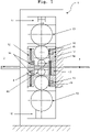
- FIG 1 shows a schematic front view of a six-high rolling mill stand 1 according to the invention for hot rolling an intermediate strip 2 into a thin strip 3.
- the intermediate strip 2 is hot rolled between the rolling gap between the upper work roll 4a and the lower work roll 4b.
- the work rolls 4a, 4b are journaled in roll chocks and may be bent by two work roll bending blocks 8.
- the work roll bending block 8 on the entry side of the mill stand 1 features two stabilizing devices 16 for locking the work rolls 4a, 4b during hot rolling.
- the work rolls 4a, 4b are supported by two intermediate rolls 10 in the mill stand.
- the intermediate rolls 10 are journaled in roll chocks and may be bent by four intermediate roll bending blocks 12.
- the bending forces from the work roll bending blocks 8 and the intermediate roll bending blocks 12 are shown by arrows on the exit side and on the entry side of the mill stand 1, respectively. For reasons of clarity, the bending forces are shown on one side of the mill stand 1 only, although they are present on both sides.
- the intermediate rolls 10 are supported by two so-called backup rolls 13 in the mill stand. Also the backup rolls 13 are journaled in roll chocks, however, no bending blocks for bending the backup rolls 13 are present.
- one hydraulic cylinder 17 is present to move the roll chocks journaling the backup rolls 13 in the mill stand 1.
- the pass line level of the work roll 4b is set by the pass line adjusting device 18.
- stabilizing devices 16 are present on the exit side of the mill stand 1 between the intermediate roll bending blocks 12 and the roll chocks. It is possible that further stabilizing devices 16 are present on the entry side of the mill stand and between the roll chocks and work roll bending blocks 8.
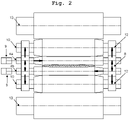
- each work roll 4a, 4b features a tapered section, followed by a typically ground running surface, and a cylindrical surface.
- the upper work roll 4a is arranged opposite to the lower work roll 4b.
- Both work rolls 4a, 4b are connected to a respective separate axial shifting device 9 that allows the shifting of the work rolls 4a, 4b in opposite horizontal directions, i.e. the upper work roll 4a to the right and the lower work roll 4b to the left (see horizontal arrows).
- the work roll bending blocks 8 and the intermediate bending blocks 12 are shown schematically.
- Each work roll 4a, 4b features a tapered portion 7, in axial direction followed by a running surface 6 and a cylindrical portion 5.
- Each intermediate roll 10 features two tapered portions 7 and an intermediate portion 11 in-between.
- the bending forces FB1 acting on the upper work roll 4a and the bending forces FB2 acting on the intermediate roll 10 as well as the force FS shifting the work roll 4a in a horizontal, axial direction are depicted by arrows.
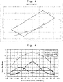
- FIG 4 the control range of the work roll bending blocks 8 and the intermediate bending blocks 12 depicted in FIGs 1 and 2 of a six-high rolling mill stand according to the invention are compared to the control range of the work roll bending block 8 for a 4-high rolling mill stand. It is evident that the combination of the w ork r oll bending b locks (in the diagram labelled WRB) with the i ntermediate r oll bending b locks (short IRB) results in a much wider control range for both the quadratic component A2 and the quartic component A4.
- the six-high rolling mill stands 1 according to the invention are therefore superior to 4-high rolling mill stands in terms of geometry control of the rolled thin strip.
- FIGs 5a and 5b depict the upper and lower work rolls 4a, 4b of the six-high rolling mill stand with one work roll cooling device 14 on the entry and three work roll cooling devices 14 on the exit side of the mill stand per work roll, respectively.
- the intermediate rolls and the backup rolls are not depicted in these FIGs.
- one work roll cooling device 14 is present per work roll.
- This work roll cooling device 14 allows the individual cooling of 12 axially spaced cooling zones Z1...Z12 of the running surface 6 of the work roll 4a, 4b (see FIG 5b ).
- the cooling intensity of each zone Z1...Z12 may be adjusted independently by a separate valve 15.
- the valve 15 can either adjust the pressure of the cooling fluid, which consequently changes the flow rate through the spraying nozzle or change the opening time in which the valve 15 is fully open.
- the change of the opening time also adjusts the total amount of the cooling fluid passing through the spraying nozzle per cycle (see so-called pulse width modulation, short PWM).
- three work roll cooling devices 14 are present. Each work roll cooling device 14 again features at least one valve 15 for setting the effective flow rate through the cooling nozzle.
- the cooling zones cover the running surface 6 of the work rolls 4a, 4b only, and possibly some overlap with the tapered portion and/or the cylindrical portion of the work rolls exists. Therefore, e.g. only the cooling zones Z3... Z12 depicted in FIG 5b are switched on.
- the cooling devices 14 remain stationary even though the work rolls 4a, 4b may be shifted in an axial direction.
- the cooling devices 14 do not remain stationary and are shifted axially synchronously with the respective work rolls.
- the shifting of the cooling devices 14 can take place by either the long stroke axial shifting devices shifting the work rolls, or by separate axial shifting devices.
- the cooling zones cover both the tapered portion 7 and the running surface 6 of the work rolls.
- the cooling zone Z3...Z12 are switched on and the valves 15 for the cooling zones Z1 and Z2 are closed.
- the zones Z1... Z10 are switched on and the valves 15 for zones Z11 and Z12 are shut off. By doing so, the regions of the work rolls contacting the strip are cooled at all times.
- FIG 6 shows the specific flow rates of the three work roll cooling devices 14 located on the exit side of the mill stand of FIG 5 .
- One of the work roll cooling devices 14 supplies the basic cooling of the work roll, amounting to 30% of the max. total cooling intensity.
- the basic cooling is almost constant across the width of the work roll, falling to some 70% at the edges.
- the additional cooling #1 amounts to 35% of the max. total cooling intensity and follows a cosine function with its peak at the centre of the barrel.
- the additional cooling #2 also amounts to 35% of the max. total cooling intensity and follows a negative cosine function with its minimum at the centre of the barrel.
- the frequency of the additional cooling function #2 is twice the frequency of the additional cooling function #1. Assuming that all three work roll cooling devices 14 operate at maximum flow, the max. cooling intensity is at the centre of the barrel (flow rate almost 4) compared to a flow rate of 1.5 at the edges of the barrel.
- the six-high rolling mill stand according to the invention is particularly advantageous for finishing rolling high quality ultra-thin steel strip with a final thickness after the last roll stand ⁇ 0.8 mm, preferably ⁇ 0.6 mm.
- the diameter of the work rolls is typically between 300 and 500 mm and consequently considerably smaller than the diameter of work rolls in four-high mill stands. The smaller diameter results in a considerably smaller rolling force at the same ratio of thickness reduction. Due to the reduced rolling force, the geometrical properties, such as profile and/or flatness, of the thin steel strip are greatly improved.
- the application of six-high rolling mill stands is particularly advantageous as the third, fourth and/or fifth mill stand in a finishing mill train of a combined casting and hot rolling installation, where thin (or ultra-thin) steel strip is produced that may serve as substitute material for cold rolled steel strip.
- FIG 7 shows a combined casting and hot rolling installation 40 featuring a continuous casting machine 41 with a bow-type strand guide 42, in which the strand coming from the mould is subjected to a liquid core and/or a soft core reduction.
- the strand having a thickness of 110 mm immediately after the mould is reduced to a thickness of 100 mm at the end of the bow-type strand guide 42.
- the reduced strand is then rough rolled in a roughing mill train 43 to a so-called intermediate strip having a thickness of 16 mm.
- the temperature of the intermediate strip can be adjusted by a heater 44. After descaling the heated intermediate strip, the intermediate strip is finish rolled in a finishing mill train 20.
- the first to third rolling step in the finishing mill train 20 are done by 4-high mill stands 21, the fourth and the fifth rolling step are done by six-high rolling mill stands 1, respectively.
- the end thickness of the ultra-thin steel strip is 0.6 mm. All rolling steps both in the roughing mill train 43 and in the finishing mill train 20 are performed on the uncut strand/strip, i.e. in endless mode.
- the profile and/or the flatness of the ultra-thin steel strip is measured by a measurement device 23. After that, the temperature of the steel strip is reduced to coiling temperature in the cooling line 22, the endless strip is cut to length/weight by shears and coiled by at least two coilers.
- the measurement device 23 continuously measures both the profile and the flatness of the thin steel strip and feeds the measurement data into a controller 30.
- the controller 30 compares the measured profile of the thin strip PR Is to the reference value for the thin strip PR Ref and creates control values for the work roll bending blocks of the 4-high rolling mill stands 21, the work roll bending blocks of the 6-high rolling mill stands 1 and the intermediate roll bending blocks of the 6-high rolling mill stands 1.
Landscapes
- Engineering & Computer Science (AREA)
- Mechanical Engineering (AREA)
- Metal Rolling (AREA)
Abstract
Description
- The invention concerns a six-high rolling mill stand (also known as sexto rolling mill stand) for hot rolling an intermediate strip into a thin strip and a method for producing a thin strip in a combined casting and rolling installation, wherein the thickness of the thin strip is < 0.8 mm.
- According to a first aspect of the invention, the invention concerns a six-high rolling mill stand for hot rolling an intermediate strip into a thin strip, the rolling mill stand comprising: an upper work roll and a lower work roll for hot rolling the intermediate strip between the upper work roll and the lower work roll into the thin strip; work roll bending blocks for bending the work rolls in vertical direction; two axial shifting devices for axially shifting the work rolls; two intermediate rolls for supporting the work rolls in vertical direction; intermediate roll bending blocks for bending the intermediate rolls in vertical direction; and two backup rolls for supporting the intermediate rolls in vertical direction.
- According to a second aspect of the invention, the invention concerns a method for producing a thin strip in a combined casting and rolling installation, wherein the thickness of the thin strip is < 0.8 mm, comprising the following steps: continuous casting a steel strand with slab or thin-slab format in a continuous casting machine; liquid-core reduction and/or soft-core reduction of the steel strand in the strand guide of the continuous casting machine, wherein the thickness of the steel strand is reduced by at least 5%; roughing rolling of the reduced steel strand to an intermediate strip in a roughing mill train, wherein the thickness of the intermediate strip is between 8 and 45 mm; finishing rolling the intermediate strip into the thin strip in a finishing mill train; measuring the profile and/or the flatness of the thin strip, wherein the measurement device is arranged in the transport direction of the strip between the last mill stand of the finishing mill train and the first cooling header of a cooling line; cooling of the thin strip to coiling temperature in the cooling line; and coiling of the cooled thin strip.
-
WO2017/215595 discloses a four-high rolling mill stand (also known as quarto rolling mill stand) for hot rolling an intermediate strip into a thin strip, the rolling mill stand comprising: an upper work roll and a lower work roll for hot rolling the intermediate strip between the upper work roll and the lower work roll into the thin strip, wherein each work roll features a cylindrical portion, in axial direction followed by a running surface, and followed by a tapered portion, wherein the upper work roll is arranged in an opposite direction to the lower work roll; and two axial shifting devices for shifting the work rolls in opposite axial directions. In addition, the document discloses a method for producing a thin strip in a combined casting and rolling installation, comprising the following steps: continuous casting a steel strand with slab or thin-slab format in a continuous casting machine; roughing rolling of the reduced steel strand to an intermediate strip in a roughing mill train; finishing rolling the intermediate strip into the thin strip in a finishing mill train; cooling of the thin strip to coiling temperature in a cooling line; and coiling of the cooled thin strip. Although the rolling mill ofWO2017/215595 is suitable for hot rolling long uninterrupted sequences without any change of the work rolls, the rolling forces become very high when producing ultra-thin strip with a thickness < 0.8 mm. -
EP3595822 discloses a six-high rolling mill stand for hot rolling an intermediate strip into a thin strip, the rolling mill stand comprising: an upper work roll and a lower work roll for hot rolling the intermediate strip between the upper work roll and the lower work roll into the thin strip; two intermediate rolls for supporting the work rolls in the vertical direction; and two backup rolls for supporting the intermediate rolls in the vertical direction. In addition, the document discloses a method for producing a thin strip in a combined casting and rolling installation, wherein the thickness of the thin strip is ≤ 0.8 mm, comprising the following steps: continuous casting a steel strand with slab or thin-slab format in a continuous casting machine; roughing rolling of the reduced steel strand to an intermediate strip in a roughing mill train, wherein the thickness of the intermediate strip is between 8 and 40 mm; finishing rolling the intermediate strip into the thin strip in a finishing mill train; cooling of the thin strip to coiling temperature in the cooling line; and coiling of the cooled thin strip. Although the rolling mill ofEP3595822 is suitable for producing ultra-thin strip with a thickness < 0.8 mm, the solution is not suitable for hot rolling long uninterrupted sequences without any change of the work rolls. - Although six-high rolling mill stands are known in the prior art, the known mill stands are either not suitable for hot rolling long uninterrupted sequences, particularly in endless mode, without any change of the work rolls, or the mill stands are not optimally suited for the production of ultra-thin strip with a thickness < 0.8 mm.
- It is the primary object of the invention to come up with a six-high rolling mill stand that is suitable for hot-rolling of ultra-thin steel strip with a thickness < 0.8 mm, say 0.6 mm and below, in a combined casting and rolling installation, whereby the hot rolling can be done in long uninterrupted sequences, particularly in endless mode, without any change of the work rolls, and very good geometry of the thin strip due to moderate rolling forces.
- Another object of the invention is to come up with a method for producing an ultra-thin steel strip in a combined casting and rolling installation with low production costs and very good geometry.
- The first object of the invention is solved by a six-high rolling mill stand for hot rolling an intermediate strip into a thin strip according to
claim 1, the rolling mill stand comprising: - an upper work roll and a lower work roll for hot rolling the intermediate strip between the upper work roll and the lower work roll into the thin strip;
- work roll bending blocks for bending the work rolls in vertical direction;
- two axial shifting devices for axially shifting the work rolls;
- two intermediate rolls for supporting the work rolls in vertical direction;
- intermediate roll bending blocks for bending the intermediate rolls in vertical direction; and
- two backup rolls for supporting the intermediate rolls in vertical direction.
- Due to the six-high arrangement of the rolling mill stand, the running surface of the work rolls may have a small diameter, e.g. between 300 and 500 mm, resulting in low rolling forces and a good geometry of the resulting thin strip. The geometry, i.e. the profile and flatness, of the thin strip can be adjusted by both the work roll bending blocks for bending the work rolls in vertical direction and the intermediate roll bending blocks for bending the intermediate rolls in vertical direction. The combination of both bending the work rolls and bending the intermediate rolls results in a broad two-dimensional field that allows the effective adjustment of profile and flatness of the rolled ultrathin strip in a broad manner.
- Compared to six-high rolling mill stands from the prior art, bending blocks for both the work rolls as well as for the two intermediate rolls are present. Typically, the upper work roll is bent by the work roll bending block in the upward vertical direction, whereas the lower work roll is bent by the work roll bending block in the downward vertical direction. The intermediate rolls may be bent in analogous directions by the intermediate roll bending blocks. Another significant difference to six-high rolling mill stands from the prior art is that each of the two intermediate rolls features a first tapered portion, in axial direction followed by an intermediate surface, and in axial direction followed by a second tapered portion. This in retrospect relatively simple modification of the intermediate roll's shape reduces the Hertz' stresses between the end regions of the running surface of the work rolls and the corresponding regions of the intermediate rolls significantly. As the edge regions in the width direction of the thin strip are most strongly affected by work roll wear, the special shape of the intermediate rolls reduces the work roll wear considerably.
- The six-high rolling mill stand according to the invention can either feature
- a) work rolls having a conventional shape, i.e. featuring a running surface, and wherein the two axial shifting devices allow the typically cyclical shifting of the work rolls in the opposite or same axial direction, or
- b) preferably work rolls having a special shape, wherein each work roll features a cylindrical portion, in axial direction followed by a running surface, and in axial direction followed by a tapered portion, wherein the upper work roll is arranged in an opposite direction to the lower work roll, and wherein the two axial shifting devices allow the shifting of the work rolls in opposite axial directions.
- The earlier mentioned embodiment has been known from conventional hot strip mills for a long time. The cyclical shifting of the work rolls aims to distribute the wear across the running surface of the work rolls.
- The latter mentioned embodiment allows even longer uninterrupted rolling sequences due to the special shape of the work rolls, each roll having a cylindrical portion, a typically ground running surface, and a tapered portion, the opposite arrangement of the work rolls in the mill stand, and two long-stroke axial shifting devices for shifting the work rolls in opposite axial directions. The shifting of the work rolls in opposite axial directions (see
WO 2017/215595 ) ensures that the wear of the work rolls has no or at least very little effect on the geometry of the thin strip. Such a six-high rolling mill stand is ideally suited for hot-rolling long uninterrupted sequences in a combined casting and rolling installation, e.g. an Arvedi ESP line. - In a preferred embodiment of the invention, the six-high rolling mill stand features two work roll cooling devices, one assigned to the upper work roll and the other assigned to the lower work roll, for the cooling of multiple, axially spaced cooling zones of the running surface of the work roll with adjustable cooling intensity. By doing so, the geometry, i.e. the profile and/or flatness, of the thin strip can be adjusted not only by bending the work rolls and the intermediate rolls, but also by cooling the running surface of the work rolls with adjustable cooling intensity. This allows an effective control of the geometry of the thin strip.
- At least one, preferably two, work roll cooling device is present on the entry side of the rolling mill and at least one, preferably two or three, work roll cooling device is present on the exit side of the rolling mill.
- The work roll cooling devices may either be shifted synchronously with the axial shifting of the work rolls or remain stationary in the axial direction. Particularly in the former case, it may be advantageous to use valves to switch off cooling zones which are no longer in contact with the strip.
- According to a preferred embodiment, the number of multiple, axially spaced cooling zones is at least three, preferably at least five. For effectively controlling the geometry of the rolled strip, the number of cooling zones can be increased further, e.g. up to 29.
- It is preferred to use work rolls having a diameter between 300 and 500 mm, and/or to use intermediate rolls having a diameter between 450 and 800 mm. The diameter of the work rolls directly influences the rolling force during hot rolling, wherein a small diameter results in a small rolling force and vice versa.
- In order to "lock" the work-rolls and/or intermediate rolls in the vertical and horizontal direction, it is preferred that at least two stabilising devices are assigned to each work roll and/or intermediate roll. The locking can be done prior to the commencement of a rolling sequence, wherein the sequence can be conducted in endless, semi-endless or even batch rolling mode. By locking the rolls, shocks - e.g. a rapidly increasing rolling force at the beginning of the rolling sequence, do not result in a corresponding displacement of the roll in vertical and/or horizontal direction. In any case, such displacement will be a lot smaller.
- A finishing mill train according to the invention comprises: two or three, preferably three, four-high mill stands, wherein each four-high mill stand features work roll bending blocks for bending the work rolls of the mill stand in vertical direction; two or three, preferably two, six-high rolling mill stands according to the invention, wherein the four-high mill stands are arranged in the transport direction of the strip before the six-high rolling mill stands.
- As four-high mill stands are significantly simpler and cheaper than six-high rolling mill stands, it makes sense to use four-high mill stands at the beginning of the finishing mill train and to use six-high mill stands towards the end of the finishing mill train. In a preferred embodiment, all four-high mill stands are comprised in a first group and all six-high mill stands are comprised in a second group, wherein the 1st group is arranged ahead of the 2nd group.
- In a more preferred embodiment of the invention, between the last mill stand of the finishing mill train and the first cooling header of the cooling line a measurement device for measuring the profile and/or the flatness of the thin strip is arranged. The measurement device allows quality control of the rolled thin strip and - as may be seen below - can be used to feed measurement data into a controller in order to control the geometry of the thin strip in the finishing mill train.
- According to an even more preferred embodiment, the finishing mill train features a controller for controlling the profile and/or flatness of the thin strip, wherein the controller is connected to the measurement device for measuring the profile and/or the flatness of the thin strip, the work roll bending blocks of the four-high mill stands of the finishing mill train, the work roll bending blocks and the intermediate roll bending blocks of the six-high mill stands of the finishing mill train, and preferably the work roll cooling devices for cooling multiple, axially spaced cooling zones of the running surface of a work roll with adjustable cooling intensity.
- The second object of the invention is solved by a method for producing a thin strip in a combined casting and rolling installation, wherein the thickness of the thin strip is < 0.8 mm, comprising the following steps:
- continuous casting a steel strand with slab or thin-slab format in a continuous casting machine,
- liquid-core reduction and/or soft-core reduction of the steel strand in the strand guide of the continuous casting machine, wherein the thickness of the steel strand is reduced by at least 5%,
- roughing rolling of the reduced steel strand to an intermediate strip in a roughing mill train, wherein the thickness of the intermediate strip is between 8 and 45 mm,
- optionally heating the intermediate strip to a surface temperature between 900 and 1200 °C,
- finishing rolling the intermediate strip into the thin strip in a finishing mill train, wherein firstly two or three, preferably three, reduction steps are performed subsequently by four-high mill stands, and secondly, two or three, preferably two, reduction steps are performed subsequently by six-high mill stands, wherein the finishing mill train is preferably according to one of the
claims 8 to 10, - measuring the profile and/or the flatness of the thin strip, wherein the measurement device is arranged in the transport direction of the strip between the last mill stand of the finishing mill train and the first cooling header of a cooling line,
- cooling of the thin strip to coiling temperature in the cooling line, and
- coiling of the cooled thin strip.
- In the combined casting and rolling installation, a continuous casting machine continuously casts liquid steel into a steel strand with slab or thin-slab format. By reducing the thickness of the steel strand by a liquid-core and/or soft-core reduction in the strand guide of the casting machine, the metallurgical quality of the steel strand is improved, the thickness is reduced and the speed of the steel strand is increased. The so-called liquid-core reduction reduces the thickness of the strand when the centre of the strand is still liquid; likewise the so-called soft-core reduction reduces the thickness of the strand when the centre of the strand is still mushy, i.e. no longer liquid and not yet fully solidified. After the liquid-core and/or soft-core reduction, the thickness of the strand is reduced further by roughing rolling to an intermediate strip with a thickness between 8 and 45 mm. The roughing rolling is typically done by two, three or four roughing stands. In order to reach a specific, e.g. austenite or ferrite, grain in the thin strip, the last reduction step in the finishing mill train needs to be performed at a specific temperature. Depending on the length of the combined casting and rolling installation, the casting speed etc. the surface temperature of the intermediate strip may be heated to a temperature between 900 and 1200 °C. The heating may be done by induction heating preferably. In any case, the intermediate strip is finish rolled into the thin strip in a finishing mill train, wherein the first two or three, preferably three, reduction steps are performed subsequently by four-high mill stands, and after this, two or three, preferably two, reduction steps are performed subsequently by six-high mill stands. The six-high mill stands is preferably according to one of the
claims 8 to 10. After hot rolling and before cooling the thin strip to coiling temperature, the profile and/or the flatness of the thin strip is measured by a measurement device. Finally, the cooled thin strip is coiled. - According to a first preferred embodiment, the roughing rolling is performed on the uncut steel strand, the finishing rolling is performed on the uncut intermediate strip, preferably the cooling is performed on the uncut thin strip, and the thin strip is cut before the coiling of the cooled thin strip.
- This embodiment is particularly suitable for traditional combined casting and rolling installations, wherein the continuous casting machine, the roughing mill train, the finishing mill train, the cooling line and the coilers are aligned in-line. The endless operation of the casting and rolling installation allows the production of ultra-thin steel strip without the risk of cobbles in the line due to strip heads moving with high speed and getting caught by auxiliary devices. Due to the endless operation, no strip heads are present and in the steel strand, the intermediate strip and the thin strip some tension is present, such that a "flying strip head" cannot occur.
- According to a second preferred embodiment, the steel strand is cut to slabs before roughing rolling, the slabs are roughing rolled into intermediate strips, the intermediate strips are joined together before finishing rolling, the finishing rolling is performed on the joined intermediate strips, preferably the cooling is performed on the uncut thin strip, and the thin strip is cut before the coiling of the cooled thin strip.
- This embodiment allows the production of 4 Million metric tons / year on a single casting and rolling installation having more than 1 continuous casting machine. Also in this case, the finishing rolling and the cooling take place in an uncut fashion, whereby the risk of a "flying strip head" is greatly reduced.
- In another preferred embodiment of the invention, the profile and/or the flatness of the thin strip is controlled by a controller taking into account the measured profile and/or flatness of the thin strip by setting
- the bending of the work rolls of the four-high mill stands of the finishing mill train,
- the bending of both the work rolls and the intermediate rolls of the six-high mill stands of the finishing mill train, and
- preferably the cooling of multiple, axially spaced cooling zones of the running surface of the work rolls of the six-high mill stands of the finishing mill train with a pre-set cooling intensity.
- Further advantages and features of the present invention are provided by the following description of non-restrictive exemplary embodiments, wherein the figures show:
-
FIG 1 a schematic showing a six-high rolling mill stand according to the invention in a partially cut front view, -
FIG 2 a schematic showing the work, intermediate and backup rolls of the six-high rolling mill stand ofFIG 1 , -
FIG 3 a schematic showing the upper work roll, the upper intermediate roll and the upper backup roll ofFIG 2 separately in greater detail, -
FIG 4 a diagram showing the control range in a 4-high rolling mill stand according to the prior art and a 6-high rolling mill stand according to the invention, -
FIG 5a and 5b a schematic showing the work roll cooling device for cooling multiple, axially separated cooling zones of the work roll, -
FIG 6 a diagram showing the specific flow rates of the work roll cooling device ofFIG 5a and 5b in the width direction of the work roll, and -
FIG 7 a schematic showing a combined casting and rolling line having two six-high rolling stands in the finishing rolling train. -
FIG 1 shows a schematic front view of a six-highrolling mill stand 1 according to the invention for hot rolling anintermediate strip 2 into athin strip 3. Theintermediate strip 2 is hot rolled between the rolling gap between theupper work roll 4a and thelower work roll 4b. The work rolls 4a, 4b are journaled in roll chocks and may be bent by two work roll bending blocks 8. The workroll bending block 8 on the entry side of themill stand 1 features two stabilizingdevices 16 for locking the work rolls 4a, 4b during hot rolling. The work rolls 4a, 4b are supported by twointermediate rolls 10 in the mill stand. Also theintermediate rolls 10 are journaled in roll chocks and may be bent by four intermediate roll bending blocks 12. The bending forces from the workroll bending blocks 8 and the intermediate roll bending blocks 12 are shown by arrows on the exit side and on the entry side of themill stand 1, respectively. For reasons of clarity, the bending forces are shown on one side of themill stand 1 only, although they are present on both sides. The intermediate rolls 10 are supported by two so-called backup rolls 13 in the mill stand. Also the backup rolls 13 are journaled in roll chocks, however, no bending blocks for bending the backup rolls 13 are present. In order to change the rolling gap between the upper and thelower work roll hydraulic cylinder 17 is present to move the roll chocks journaling the backup rolls 13 in themill stand 1. The pass line level of thework roll 4b is set by the passline adjusting device 18. As the backup rolls 13 are in contact with theintermediate rolls 10 and theintermediate rolls 10 are in contact with the work rolls 4a, 4b, the rolling gap is changed by thehydraulic cylinder 17. As depicted inFIG 1 , stabilizingdevices 16 are present on the exit side of themill stand 1 between the intermediate roll bending blocks 12 and the roll chocks. It is possible that further stabilizingdevices 16 are present on the entry side of the mill stand and between the roll chocks and work roll bending blocks 8. - The work rolls 4a, 4b and the work roll bending blocks 8, the
intermediate rolls 10 and the intermediate bending blocks 12, the backup rolls 13 and theaxial shifting devices 9 are shown again inFIG 2 in a side view. It is immediately apparent that eachwork roll upper work roll 4a is arranged opposite to thelower work roll 4b. Both work rolls 4a, 4b are connected to a respective separateaxial shifting device 9 that allows the shifting of the work rolls 4a, 4b in opposite horizontal directions, i.e. theupper work roll 4a to the right and thelower work roll 4b to the left (see horizontal arrows). The workroll bending blocks 8 and the intermediate bending blocks 12 are shown schematically. - The different portions of the work rolls 4a, 4b, the
intermediate rolls 10 and the backup rolls 13 are depicted inFIG 3 . Eachwork roll portion 7, in axial direction followed by a runningsurface 6 and acylindrical portion 5. Eachintermediate roll 10 features twotapered portions 7 and anintermediate portion 11 in-between. The bending forces FB1 acting on theupper work roll 4a and the bending forces FB2 acting on theintermediate roll 10 as well as the force FS shifting thework roll 4a in a horizontal, axial direction are depicted by arrows. - In
FIG 4 the control range of the workroll bending blocks 8 and the intermediate bending blocks 12 depicted inFIGs 1 and2 of a six-high rolling mill stand according to the invention are compared to the control range of the workroll bending block 8 for a 4-high rolling mill stand. It is evident that the combination of the work roll bending blocks (in the diagram labelled WRB) with the intermediate roll bending blocks (short IRB) results in a much wider control range for both the quadratic component A2 and the quartic component A4. The six-high rolling mill stands 1 according to the invention are therefore superior to 4-high rolling mill stands in terms of geometry control of the rolled thin strip. -
FIGs 5a and 5b depict the upper and lower work rolls 4a, 4b of the six-high rolling mill stand with one workroll cooling device 14 on the entry and three workroll cooling devices 14 on the exit side of the mill stand per work roll, respectively. For sake of conciseness, the intermediate rolls and the backup rolls are not depicted in these FIGs. On the entry side of the mill stand, one workroll cooling device 14 is present per work roll. This workroll cooling device 14 allows the individual cooling of 12 axially spaced cooling zones Z1...Z12 of the runningsurface 6 of thework roll FIG 5b ). In other words, the cooling intensity of each zone Z1...Z12 may be adjusted independently by aseparate valve 15. Thevalve 15 can either adjust the pressure of the cooling fluid, which consequently changes the flow rate through the spraying nozzle or change the opening time in which thevalve 15 is fully open. The change of the opening time also adjusts the total amount of the cooling fluid passing through the spraying nozzle per cycle (see so-called pulse width modulation, short PWM). On the exit side of the mill stand, three workroll cooling devices 14 are present. Each workroll cooling device 14 again features at least onevalve 15 for setting the effective flow rate through the cooling nozzle. - With respect to
FIG 5b it is noted that according to a simple first embodiment of the invention, it is in most cases sufficient that the cooling zones cover the runningsurface 6 of the work rolls 4a, 4b only, and possibly some overlap with the tapered portion and/or the cylindrical portion of the work rolls exists. Therefore, e.g. only the cooling zones Z3... Z12 depicted inFIG 5b are switched on. In this case, thecooling devices 14 remain stationary even though the work rolls 4a, 4b may be shifted in an axial direction. According to an alternative embodiment of the invention, thecooling devices 14 do not remain stationary and are shifted axially synchronously with the respective work rolls. The shifting of thecooling devices 14 can take place by either the long stroke axial shifting devices shifting the work rolls, or by separate axial shifting devices. In either case, it is advantageous that the cooling zones cover both the taperedportion 7 and the runningsurface 6 of the work rolls. At the beginning of a rolling sequence, only the cooling zone Z3...Z12 are switched on and thevalves 15 for the cooling zones Z1 and Z2 are closed. Towards the end of the rolling campaign and as theupper work roll 4a is shifted to the right during rolling, the zones Z1... Z10 are switched on and thevalves 15 for zones Z11 and Z12 are shut off. By doing so, the regions of the work rolls contacting the strip are cooled at all times. -
FIG 6 shows the specific flow rates of the three workroll cooling devices 14 located on the exit side of the mill stand ofFIG 5 . One of the workroll cooling devices 14 supplies the basic cooling of the work roll, amounting to 30% of the max. total cooling intensity. The basic cooling is almost constant across the width of the work roll, falling to some 70% at the edges. Theadditional cooling # 1 amounts to 35% of the max. total cooling intensity and follows a cosine function with its peak at the centre of the barrel. Theadditional cooling # 2 also amounts to 35% of the max. total cooling intensity and follows a negative cosine function with its minimum at the centre of the barrel. The frequency of the additionalcooling function # 2 is twice the frequency of the additionalcooling function # 1. Assuming that all three workroll cooling devices 14 operate at maximum flow, the max. cooling intensity is at the centre of the barrel (flow rate almost 4) compared to a flow rate of 1.5 at the edges of the barrel. - The six-high rolling mill stand according to the invention is particularly advantageous for finishing rolling high quality ultra-thin steel strip with a final thickness after the last roll stand < 0.8 mm, preferably ≤ 0.6 mm. The diameter of the work rolls is typically between 300 and 500 mm and consequently considerably smaller than the diameter of work rolls in four-high mill stands. The smaller diameter results in a considerably smaller rolling force at the same ratio of thickness reduction. Due to the reduced rolling force, the geometrical properties, such as profile and/or flatness, of the thin steel strip are greatly improved. The application of six-high rolling mill stands is particularly advantageous as the third, fourth and/or fifth mill stand in a finishing mill train of a combined casting and hot rolling installation, where thin (or ultra-thin) steel strip is produced that may serve as substitute material for cold rolled steel strip.
-
FIG 7 shows a combined casting andhot rolling installation 40 featuring acontinuous casting machine 41 with a bow-type strand guide 42, in which the strand coming from the mould is subjected to a liquid core and/or a soft core reduction. By doing so, the strand having a thickness of 110 mm immediately after the mould is reduced to a thickness of 100 mm at the end of the bow-type strand guide 42. The reduced strand is then rough rolled in aroughing mill train 43 to a so-called intermediate strip having a thickness of 16 mm. The temperature of the intermediate strip can be adjusted by aheater 44. After descaling the heated intermediate strip, the intermediate strip is finish rolled in a finishingmill train 20. The first to third rolling step in the finishingmill train 20 are done by 4-high mill stands 21, the fourth and the fifth rolling step are done by six-high rolling mill stands 1, respectively. The end thickness of the ultra-thin steel strip is 0.6 mm. All rolling steps both in theroughing mill train 43 and in the finishingmill train 20 are performed on the uncut strand/strip, i.e. in endless mode. After the finishing rolling, the profile and/or the flatness of the ultra-thin steel strip is measured by ameasurement device 23. After that, the temperature of the steel strip is reduced to coiling temperature in thecooling line 22, the endless strip is cut to length/weight by shears and coiled by at least two coilers. In order to produce ultra-thin strip with top notch geometrical properties, themeasurement device 23 continuously measures both the profile and the flatness of the thin steel strip and feeds the measurement data into acontroller 30. As depicted, thecontroller 30 compares the measured profile of the thin strip PRIs to the reference value for the thin strip PRRef and creates control values for the work roll bending blocks of the 4-high rolling mill stands 21, the work roll bending blocks of the 6-high rolling mill stands 1 and the intermediate roll bending blocks of the 6-high rolling mill stands 1. By doing so, the geometric properties of the ultra-thin steel strip are equally good or at least almost comparable to cold rolled steel strip produced by state of the art technologies. - Although the invention has been illustrated more specifically and described in detail by the preferred exemplary embodiments, the invention is not restricted by the examples disclosed and other variations can be derived therefrom by a person skilled in the art without departing from the scope of protection of the invention.
-
- 1
- Six-high rolling mill stand
- 2
- Intermediate strip
- 3
- Thin strip
- 4a
- Upper work roll
- 4b
- Lower work roll
- 5
- Cylindrical portion
- 6
- Running surface
- 7
- Tapered portion
- 8
- Work roll bending block
- 9
- Axial shifting device
- 10
- Intermediate roll
- 11
- Intermediate portion
- 12
- Intermediate roll bending block
- 13
- Backup roll
- 14
- Work roll cooling device
- 15
- Valve
- 16
- Stabilising device
- 17
- Hydraulic cylinder
- 18
- Pass line adjusting device
- 20
- Finishing mill train
- 21
- Four-high rolling mill stand
- 22
- Cooling line
- 23
- Measurement device
- 30
- Controller
- 40
- Combined casting and rolling installation
- 41
- Continuous casting machine
- 42
- Strand guide
- 43
- Roughing mill train
- 44
- Heater
- FB1, FB2
- Bending force
- FS
- Displacement force
- PRIs
- Measured profile of the thin strip
- PRRef
- Reference value of the profile of the thin strip
- Z1...Z12
- Axially spaced cooling zone
Claims (14)
- Six-high rolling mill stand (1) for hot rolling an intermediate strip (2) into a thin strip (3), the rolling mill stand comprising:- an upper work roll (4a) and a lower work roll (4b) for hot rolling the intermediate strip (2) between the upper work roll (4a) and the lower work roll (4b) into the thin strip (3),- work roll bending blocks (8) for bending the work rolls (4a, 4b) in vertical direction;- two axial shifting devices (9) for axially shifting the work rolls (4a, 4b);- two intermediate rolls (10) for supporting the work rolls (4a, 4b) in vertical direction,
wherein each intermediate roll (10) has a first tapered portion (7), in axial direction followed by an intermediate surface (11), and followed by a second tapered portion (7);- intermediate roll bending blocks (12) for bending the intermediate rolls (10) in vertical direction; and- two backup rolls (13) for supporting the intermediate rolls (10) in vertical direction. - Six-high rolling mill stand (1) according to claim 1,wherein each work roll (4a, 4b) features a cylindrical portion (5), in axial direction followed by a running surface (6), and followed by a tapered portion (7),wherein the upper work roll (4a) is arranged in an opposite direction to the lower work roll (4b); andwherein the two axial shifting devices (9) allow the shifting the work rolls (4a, 4b) in opposite axial directions.
- Six-high rolling mill stand according to claim 1 or 2, comprising at least two work roll cooling devices (14), wherein each work roll cooling device (14) allows the cooling of multiple, axially spaced cooling zones (Z1... Z12) of the running surface (6) of a work roll (4a, 4b) with adjustable cooling intensity.
- Six-high rolling mill stand according to claim 3, wherein the number of multiple, axially spaced cooling zones (Z1... Z12) is at least three, preferably at least five, more preferably at least 9.
- Six-high rolling mill stand according to one of the preceding claims, wherein the diameter of a work roll (4a, 4b) is between 300 and 500 mm, and/or wherein the diameter of an intermediate roll (10) is between 450 and 800 mm.
- Six-high rolling mill stand according to one of the preceding claims, wherein at least two stabilising devices (16) are assigned to each intermediate roll (10) for stabilizing the intermediate roll during rolling in the horizontal and vertical direction.
- Six-high rolling mill stand according to one of the preceding claims, wherein at least two stabilising devices (16) are assigned to each work roll (4a, 4b) for stabilizing the work roll during rolling in the horizontal and vertical direction.
- Finishing mill train (20) for hot rolling an intermediate strip (2) into a thin strip (3), wherein the thickness of the thin strip (3) is < 0.8 mm, the finishing mill comprising:- two or three, preferably three, four-high mill stands (21), wherein each four-high mill stand (21) features work roll bending blocks for bending the work rolls of the mill stand in the vertical direction,- two or three, preferably two, six-high rolling mill stands (1) according to one of the preceding claims, wherein the four-high mill (21) stands are arranged in the transport direction of the strip before the six-high rolling mill stands (1).
- Finishing mill train according to claim 8, additionally comprising:- a cooling line (22) for cooling the thin strip (3) to coiling temperature,- a measurement device (23) for measuring the profile and/or the flatness of the thin strip (3), wherein the measurement device (23) is arranged in the transport direction of the strip between the last mill stand (1) of the finishing mill train (20) and the first cooling header of the cooling line (22).
- Finishing mill according to claim 9, additionally comprising:- a controller (30) for controlling the profile and/or flatness of the thin strip (3), wherein the controller (30) is connected to- the measurement device (23) for measuring the profile and/or the flatness of the thin strip (3),- the work roll bending blocks (8) of the four-high mill stands (21) of the finishing mill train (20),- the work roll bending blocks (8) and the intermediate roll bending blocks (12) of the six-high mill stands (1) of the finishing mill train (20), and- preferably the work roll cooling devices (14) for cooling multiple, axially spaced cooling zones (Z1... Z12) of the running surface (6) of a work roll (4a, 4b) with adjustable cooling intensity.
- Method for producing a thin strip (3) in a combined casting and rolling installation (40), wherein the thickness of the thin strip (3) is < 0.8 mm, comprising the following steps:- continuous casting a steel strand with slab or thin-slab format in a continuous casting machine (41);- liquid-core reduction and/or soft-core reduction of the steel strand in the strand guide (42) of the continuous casting machine (41), wherein the thickness of the steel strand is reduced by at least 5%, preferably between 5 and 20%;- roughing rolling of the reduced steel strand to an intermediate strip (2) in a roughing mill train (43), wherein the thickness of the intermediate strip (2) is between 8 and 45 mm;- optionally heating the intermediate strip (2) to a surface temperature between 900 and 1200 °C;- finishing rolling the intermediate strip (2) into the thin strip (3) in a finishing mill train (20), wherein firstly two or three, preferably three, reduction steps are performed subsequently by four-high mill stands (21), and secondly, two or three, preferably two, reduction steps are performed subsequently by six-high mill stands (1), wherein the finishing mill train (20) is preferably according to one of the claims 8 to 10;- measuring the profile and/or the flatness of the thin strip (3), wherein the measurement device (23) is arranged in the transport direction of the strip between the last mill stand (1) of the finishing mill train (20) and the first cooling header of a cooling line (22);- cooling of the thin strip (3) to coiling temperature in the cooling line; and- coiling of the cooled thin strip.
- Method according to claim 11, wherein the roughing rolling is performed on the uncut steel strand, the finishing rolling is performed on the uncut intermediate strip, preferably the cooling is performed on the uncut thin strip, and the thin strip is cut before the coiling of the cooled thin strip.
- Method according to claim 11, wherein the steel strand is cut to slabs before roughing rolling, roughing rolling the slabs into intermediate strips, wherein the intermediate strips are joined together before finishing rolling, finishing rolling is performed on the joined intermediate strips, preferably the cooling is performed on the uncut thin strip, and the thin strip is cut before the coiling of the cooled thin strip.
- Method according to claim 11, wherein the profile and/or the flatness of the thin strip (3) is controlled by a controller (30) taking into account the measured profile and/or flatness of the thin strip (3) by setting- the bending of the work rolls of the four-high mill stands (21) of the finishing mill train (20),- the bending of both the work rolls (4a, 4b) and the intermediate rolls (10) of the six-high mill stands (1) of the finishing mill train (20), and- preferably the cooling of multiple, axially spaced cooling zones (Z1...Z12) of the running surface (6) of the work rolls (4a, 4b) of the six-high mill stands (1) of the finishing mill train (20) with a pre-set cooling intensity.
Priority Applications (6)
| Application Number | Priority Date | Filing Date | Title |
|---|---|---|---|
| EP21187459.9A EP4122612A1 (en) | 2021-07-23 | 2021-07-23 | Six-high rolling mill stand and finishing mill train for hot rolling an intermediate strip into a thin strip |
| CN202280051387.6A CN117677447A (en) | 2021-07-23 | 2022-07-21 | Six-high rolling mill stand and finishing mill for hot rolling of intermediate strip into thin strip |
| ES22754076T ES3039633T3 (en) | 2021-07-23 | 2022-07-21 | Six-high rolling mill stand, finishing mill train for hot rolling an intermediate strip into a thin strip and method for producing a thin strip |
| US18/291,192 US12233443B2 (en) | 2021-07-23 | 2022-07-21 | Six-high rolling mill stand and finishing mill train for hot rolling an intermediate strip into a thin strip |
| PCT/EP2022/070546 WO2023001985A1 (en) | 2021-07-23 | 2022-07-21 | Six-high rolling mill stand and finishing mill train for hot rolling an intermediate strip into a thin strip |
| EP22754076.2A EP4373623B8 (en) | 2021-07-23 | 2022-07-21 | Six-high rolling mill stand, finishing mill train for hot rolling an intermediate strip into a thin strip and method for producing a thin strip |
Applications Claiming Priority (1)
| Application Number | Priority Date | Filing Date | Title |
|---|---|---|---|
| EP21187459.9A EP4122612A1 (en) | 2021-07-23 | 2021-07-23 | Six-high rolling mill stand and finishing mill train for hot rolling an intermediate strip into a thin strip |
Publications (1)
| Publication Number | Publication Date |
|---|---|
| EP4122612A1 true EP4122612A1 (en) | 2023-01-25 |
Family
ID=77179885
Family Applications (2)
| Application Number | Title | Priority Date | Filing Date |
|---|---|---|---|
| EP21187459.9A Withdrawn EP4122612A1 (en) | 2021-07-23 | 2021-07-23 | Six-high rolling mill stand and finishing mill train for hot rolling an intermediate strip into a thin strip |
| EP22754076.2A Active EP4373623B8 (en) | 2021-07-23 | 2022-07-21 | Six-high rolling mill stand, finishing mill train for hot rolling an intermediate strip into a thin strip and method for producing a thin strip |
Family Applications After (1)
| Application Number | Title | Priority Date | Filing Date |
|---|---|---|---|
| EP22754076.2A Active EP4373623B8 (en) | 2021-07-23 | 2022-07-21 | Six-high rolling mill stand, finishing mill train for hot rolling an intermediate strip into a thin strip and method for producing a thin strip |
Country Status (5)
| Country | Link |
|---|---|
| US (1) | US12233443B2 (en) |
| EP (2) | EP4122612A1 (en) |
| CN (1) | CN117677447A (en) |
| ES (1) | ES3039633T3 (en) |
| WO (1) | WO2023001985A1 (en) |
Cited By (1)
| Publication number | Priority date | Publication date | Assignee | Title |
|---|---|---|---|---|
| CN119406924A (en) * | 2025-01-03 | 2025-02-11 | 安徽擎天伟嘉装备制造有限公司 | A forming roller mill for sheet metal thin plate production |
Families Citing this family (1)
| Publication number | Priority date | Publication date | Assignee | Title |
|---|---|---|---|---|
| WO2025000099A1 (en) * | 2023-06-28 | 2025-01-02 | Maynard Dokken | Bio-origin validation engine with ownership rights management and certification apparatus, system and method |
Citations (8)
| Publication number | Priority date | Publication date | Assignee | Title |
|---|---|---|---|---|
| EP0411516A2 (en) * | 1989-08-01 | 1991-02-06 | SUNDWIGER EISENHÜTTE MASCHINENFABRIK GmbH & CO. | Four- or six-rolling mill with laterally supported workrolls |
| EP0510713A1 (en) * | 1991-04-26 | 1992-10-28 | Hitachi, Ltd. | Method and apparatus for joining hot strips |
| US5622073A (en) * | 1991-05-16 | 1997-04-22 | Kawasaki Steel Corporation | Six high rolling mill |
| EP1228818A2 (en) * | 2001-02-05 | 2002-08-07 | Hitachi, Ltd. | Rolling method for strip rolling mill and strip rolling equipment |
| WO2006042606A1 (en) * | 2004-10-13 | 2006-04-27 | Siemens Vai Metals Technologies Gmbh & Co | Method and device for continuously producing a thin metal strip |
| EP2441540A1 (en) * | 2010-10-12 | 2012-04-18 | Siemens VAI Metals Technologies GmbH | Method and assembly for energy-efficient production of hot rolled steel strips |
| WO2017215595A1 (en) | 2016-06-15 | 2017-12-21 | Rizhao Baohua New Material Co., Ltd. | Mill rolls capable of rolling long kilometres for esp production line |
| EP3595822A1 (en) | 2017-03-15 | 2020-01-22 | Danieli & C. Officine Meccaniche S.p.A. | Combined continuous casting and metal strip hot-rolling plant |
Family Cites Families (7)
| Publication number | Priority date | Publication date | Assignee | Title |
|---|---|---|---|---|
| JPS6017601B2 (en) * | 1977-07-01 | 1985-05-04 | 株式会社日立製作所 | 6-high rolling mill |
| JP3174457B2 (en) * | 1994-05-17 | 2001-06-11 | 株式会社日立製作所 | Continuous casting direct hot rolling equipment and rolling method |
| CN101229560B (en) * | 2008-01-30 | 2014-07-09 | 武汉钢铁(集团)公司 | Continuous variational convexity degree rolling mill back-up shaft |
| CN101249505A (en) * | 2008-04-05 | 2008-08-27 | 无锡五冶金属压延有限公司 | Roller device of cold calender |
| DE102009060641A1 (en) * | 2009-07-07 | 2011-01-13 | Sms Siemag Ag | Device for locking the chock and the thrust bearing housing of a set of rollers and the roll changing car |
| JP5905322B2 (en) * | 2012-04-25 | 2016-04-20 | Primetals Technologies Japan株式会社 | Rolling mill with work roll shift function |
| JP6470134B2 (en) * | 2015-07-08 | 2019-02-13 | Primetals Technologies Japan株式会社 | Rolling mill and rolling method |
-
2021
- 2021-07-23 EP EP21187459.9A patent/EP4122612A1/en not_active Withdrawn
-
2022
- 2022-07-21 EP EP22754076.2A patent/EP4373623B8/en active Active
- 2022-07-21 US US18/291,192 patent/US12233443B2/en active Active
- 2022-07-21 CN CN202280051387.6A patent/CN117677447A/en active Pending
- 2022-07-21 ES ES22754076T patent/ES3039633T3/en active Active
- 2022-07-21 WO PCT/EP2022/070546 patent/WO2023001985A1/en not_active Ceased
Patent Citations (8)
| Publication number | Priority date | Publication date | Assignee | Title |
|---|---|---|---|---|
| EP0411516A2 (en) * | 1989-08-01 | 1991-02-06 | SUNDWIGER EISENHÜTTE MASCHINENFABRIK GmbH & CO. | Four- or six-rolling mill with laterally supported workrolls |
| EP0510713A1 (en) * | 1991-04-26 | 1992-10-28 | Hitachi, Ltd. | Method and apparatus for joining hot strips |
| US5622073A (en) * | 1991-05-16 | 1997-04-22 | Kawasaki Steel Corporation | Six high rolling mill |
| EP1228818A2 (en) * | 2001-02-05 | 2002-08-07 | Hitachi, Ltd. | Rolling method for strip rolling mill and strip rolling equipment |
| WO2006042606A1 (en) * | 2004-10-13 | 2006-04-27 | Siemens Vai Metals Technologies Gmbh & Co | Method and device for continuously producing a thin metal strip |
| EP2441540A1 (en) * | 2010-10-12 | 2012-04-18 | Siemens VAI Metals Technologies GmbH | Method and assembly for energy-efficient production of hot rolled steel strips |
| WO2017215595A1 (en) | 2016-06-15 | 2017-12-21 | Rizhao Baohua New Material Co., Ltd. | Mill rolls capable of rolling long kilometres for esp production line |
| EP3595822A1 (en) | 2017-03-15 | 2020-01-22 | Danieli & C. Officine Meccaniche S.p.A. | Combined continuous casting and metal strip hot-rolling plant |
Cited By (1)
| Publication number | Priority date | Publication date | Assignee | Title |
|---|---|---|---|---|
| CN119406924A (en) * | 2025-01-03 | 2025-02-11 | 安徽擎天伟嘉装备制造有限公司 | A forming roller mill for sheet metal thin plate production |
Also Published As
| Publication number | Publication date |
|---|---|
| EP4373623A1 (en) | 2024-05-29 |
| CN117677447A (en) | 2024-03-08 |
| US20240359224A1 (en) | 2024-10-31 |
| ES3039633T3 (en) | 2025-10-23 |
| US12233443B2 (en) | 2025-02-25 |
| WO2023001985A1 (en) | 2023-01-26 |
| EP4373623B8 (en) | 2025-08-27 |
| EP4373623B1 (en) | 2025-07-02 |
| EP4373623C0 (en) | 2025-07-02 |
Similar Documents
| Publication | Publication Date | Title |
|---|---|---|
| EP4087692B1 (en) | Method and apparatus for producing flat metal products | |
| AU745206B2 (en) | Method and installation for the continuous production of hot-rolled, thin flat products | |
| US5435164A (en) | Apparatus and method for the manufacture of hot rolled metal strip | |
| US6286354B1 (en) | Rolling mill and rolling method and rolling equipment | |
| US9296027B2 (en) | Method and plant for the energy-efficient production of hot steel strip | |
| US20130160277A1 (en) | Rolling line and relative method | |
| EP4373623B1 (en) | Six-high rolling mill stand, finishing mill train for hot rolling an intermediate strip into a thin strip and method for producing a thin strip | |
| EP2670539B1 (en) | Rolling method for strip and corresponding rolling line | |
| TWI615210B (en) | Installation based on the csp concept and method for operating such an installation | |
| RU2647417C2 (en) | Method of managing influence on geometry of rolled material and control device for this purpose | |
| Wang et al. | Design and application of an optimum backup roll contour configured with CVC work roll in hot strip mill | |
| EP0896840B1 (en) | Rolling mill and rolling method and rolling equipment | |
| US8186422B2 (en) | Method for the continuous casting of thin metal strip and continuous casting installation | |
| CN115943001A (en) | Casting-rolling plants for the manufacture of hot-rolled finished strip from molten steel | |
| JPH01233005A (en) | Method for controlling plate width in hot rolling of thin cast billet | |
| US20230330740A1 (en) | Method to produce a metal strip, and production plant implementing said method | |
| RU2380181C1 (en) | Method for cooling of rolled sheet on broad-strip mill of hot rolling | |
| OA19989A (en) | Method and apparatus for producing flat metal products. | |
| JPH0716694B2 (en) | Rolling method in thin plate cold rolling | |
| JPWO1997036700A1 (en) | Rolling mill, rolling method and rolling equipment |
Legal Events
| Date | Code | Title | Description |
|---|---|---|---|
| PUAI | Public reference made under article 153(3) epc to a published international application that has entered the european phase |
Free format text: ORIGINAL CODE: 0009012 |
|
| STAA | Information on the status of an ep patent application or granted ep patent |
Free format text: STATUS: THE APPLICATION HAS BEEN PUBLISHED |
|
| AK | Designated contracting states |
Kind code of ref document: A1 Designated state(s): AL AT BE BG CH CY CZ DE DK EE ES FI FR GB GR HR HU IE IS IT LI LT LU LV MC MK MT NL NO PL PT RO RS SE SI SK SM TR |
|
| STAA | Information on the status of an ep patent application or granted ep patent |
Free format text: STATUS: THE APPLICATION IS DEEMED TO BE WITHDRAWN |
|
| 18D | Application deemed to be withdrawn |
Effective date: 20230726 |
|
| RAP3 | Party data changed (applicant data changed or rights of an application transferred) |
Owner name: PRIMETALS TECHNOLOGIES AUSTRIA GMBH Owner name: PRIMETALS TECHNOLOGIES JAPAN, LTD. |