EP4122525B1 - Coupling device with coating - Google Patents
Coupling device with coating Download PDFInfo
- Publication number
- EP4122525B1 EP4122525B1 EP21186504.3A EP21186504A EP4122525B1 EP 4122525 B1 EP4122525 B1 EP 4122525B1 EP 21186504 A EP21186504 A EP 21186504A EP 4122525 B1 EP4122525 B1 EP 4122525B1
- Authority
- EP
- European Patent Office
- Prior art keywords
- housing
- coupling device
- tube
- sealing element
- fluid
- Prior art date
- Legal status (The legal status is an assumption and is not a legal conclusion. Google has not performed a legal analysis and makes no representation as to the accuracy of the status listed.)
- Active
Links
Images


Classifications
-
- A—HUMAN NECESSITIES
- A61—MEDICAL OR VETERINARY SCIENCE; HYGIENE
- A61M—DEVICES FOR INTRODUCING MEDIA INTO, OR ONTO, THE BODY; DEVICES FOR TRANSDUCING BODY MEDIA OR FOR TAKING MEDIA FROM THE BODY; DEVICES FOR PRODUCING OR ENDING SLEEP OR STUPOR
- A61M39/00—Tubes, tube connectors, tube couplings, valves, access sites or the like, specially adapted for medical use
- A61M39/10—Tube connectors; Tube couplings
-
- F—MECHANICAL ENGINEERING; LIGHTING; HEATING; WEAPONS; BLASTING
- F16—ENGINEERING ELEMENTS AND UNITS; GENERAL MEASURES FOR PRODUCING AND MAINTAINING EFFECTIVE FUNCTIONING OF MACHINES OR INSTALLATIONS; THERMAL INSULATION IN GENERAL
- F16L—PIPES; JOINTS OR FITTINGS FOR PIPES; SUPPORTS FOR PIPES, CABLES OR PROTECTIVE TUBING; MEANS FOR THERMAL INSULATION IN GENERAL
- F16L37/00—Couplings of the quick-acting type
- F16L37/28—Couplings of the quick-acting type with fluid cut-off means
- F16L37/30—Couplings of the quick-acting type with fluid cut-off means with fluid cut-off means in each of two pipe-end fittings
-
- A—HUMAN NECESSITIES
- A61—MEDICAL OR VETERINARY SCIENCE; HYGIENE
- A61M—DEVICES FOR INTRODUCING MEDIA INTO, OR ONTO, THE BODY; DEVICES FOR TRANSDUCING BODY MEDIA OR FOR TAKING MEDIA FROM THE BODY; DEVICES FOR PRODUCING OR ENDING SLEEP OR STUPOR
- A61M39/00—Tubes, tube connectors, tube couplings, valves, access sites or the like, specially adapted for medical use
- A61M39/08—Tubes; Storage means specially adapted therefor
-
- A—HUMAN NECESSITIES
- A61—MEDICAL OR VETERINARY SCIENCE; HYGIENE
- A61M—DEVICES FOR INTRODUCING MEDIA INTO, OR ONTO, THE BODY; DEVICES FOR TRANSDUCING BODY MEDIA OR FOR TAKING MEDIA FROM THE BODY; DEVICES FOR PRODUCING OR ENDING SLEEP OR STUPOR
- A61M39/00—Tubes, tube connectors, tube couplings, valves, access sites or the like, specially adapted for medical use
- A61M39/10—Tube connectors; Tube couplings
- A61M39/16—Tube connectors; Tube couplings having provision for disinfection or sterilisation
- A61M39/162—Tube connectors; Tube couplings having provision for disinfection or sterilisation with antiseptic agent incorporated within the connector
-
- F—MECHANICAL ENGINEERING; LIGHTING; HEATING; WEAPONS; BLASTING
- F16—ENGINEERING ELEMENTS AND UNITS; GENERAL MEASURES FOR PRODUCING AND MAINTAINING EFFECTIVE FUNCTIONING OF MACHINES OR INSTALLATIONS; THERMAL INSULATION IN GENERAL
- F16L—PIPES; JOINTS OR FITTINGS FOR PIPES; SUPPORTS FOR PIPES, CABLES OR PROTECTIVE TUBING; MEANS FOR THERMAL INSULATION IN GENERAL
- F16L37/00—Couplings of the quick-acting type
- F16L37/24—Couplings of the quick-acting type in which the connection is made by inserting one member axially into the other and rotating it to a limited extent, e.g. with bayonet-action
- F16L37/244—Couplings of the quick-acting type in which the connection is made by inserting one member axially into the other and rotating it to a limited extent, e.g. with bayonet-action the coupling being co-axial with the pipe
- F16L37/252—Couplings of the quick-acting type in which the connection is made by inserting one member axially into the other and rotating it to a limited extent, e.g. with bayonet-action the coupling being co-axial with the pipe the male part having lugs on its periphery penetrating into the corresponding slots provided in the female part
-
- A—HUMAN NECESSITIES
- A61—MEDICAL OR VETERINARY SCIENCE; HYGIENE
- A61M—DEVICES FOR INTRODUCING MEDIA INTO, OR ONTO, THE BODY; DEVICES FOR TRANSDUCING BODY MEDIA OR FOR TAKING MEDIA FROM THE BODY; DEVICES FOR PRODUCING OR ENDING SLEEP OR STUPOR
- A61M39/00—Tubes, tube connectors, tube couplings, valves, access sites or the like, specially adapted for medical use
- A61M39/10—Tube connectors; Tube couplings
- A61M2039/1016—Unlocking means providing a secure or comfortable disconnection
-
- A—HUMAN NECESSITIES
- A61—MEDICAL OR VETERINARY SCIENCE; HYGIENE
- A61M—DEVICES FOR INTRODUCING MEDIA INTO, OR ONTO, THE BODY; DEVICES FOR TRANSDUCING BODY MEDIA OR FOR TAKING MEDIA FROM THE BODY; DEVICES FOR PRODUCING OR ENDING SLEEP OR STUPOR
- A61M39/00—Tubes, tube connectors, tube couplings, valves, access sites or the like, specially adapted for medical use
- A61M39/10—Tube connectors; Tube couplings
- A61M2039/1072—Tube connectors; Tube couplings with a septum present in the connector
Definitions
- displacements of this kind of an element may not only be painful for the patient but may also lead to consequences of the treatment if the transferring of fluid due to the element's displacement is not performed correctly. Furthermore, it should be noted that pulling an element inserted into a patient with force could damage the vessel of a patient. Furthermore, for a patient with a compromised immune system, a wounded vessel could lead to a serious infection.
- US 4256106 A discloses a connector for the transfer of material, with the open end thereof being adapted to being connected to a mating connector.
- the open ends of the connectors are closed by deformable membranes, the outer surfaces of which can be sterilised by application of a suitable sterilising fluid.
- the second housing is insertable into the first housing via the second opening thereof, wherein the first and second sealing elements are configured to abut each other and sealingly separate the tube and the channel, wherein the cavity of at least one of the first and second sealing elements defines a first space upon contact between the first and second sealing elements.
- the tube projects through the first and second sealing elements for connection with the channel for enabling a transfer of fluid through the coupling device.
- the tube has been retracted through the first sealing element and the end portion of the tube is in close vicinity of the second sealing element.
- the ability of the coupling device to mitigate any leakage of fluid is advantageous for reasons of safety.
- any leakage from the coupling device may be particularly hazardous.
- the coupling device of the present invention may significantly increase the safety of medical staff and/or patients.
- the coupling device of the present invention is further advantageous in that its components (e.g. the first and/or second housing, the first and second sealing elements, etc.) are designed to have relatively smooth outer surfaces, such that they may be cleaned and/or disinfected in an easy and efficient manner. For example, after a cleaning and/or disinfection of a dissembled coupling device, the respective components of the coupling device may subsequently be reassembled into the coupling device.
- its components e.g. the first and/or second housing, the first and second sealing elements, etc.
- the coupling device of the present invention is further advantageous in that it is relatively inexpensive to manufacture and is easily assembled. Consequently, the coupling device may primarily be designed for single-use, i.e. the coupling device may for example be used for one patient and one therapy (e.g. infusion).
- the coupling device may for example be used for one patient and one therapy (e.g. infusion).
- the coupling device of the present invention is further advantageous in that the flow of fluid through the coupling device is linear along the principal axis of the coupling device.
- the design of the coupling device may hereby avoid an undesired turbulence of the fluid during operation of the coupling device.
- At least one of the first and second sealing elements may comprise a resilient membrane, wherein the at least one resilient membrane may have a convex shape and is configured to flatten upon abutment of the first sealing element with the second sealing element.
- the resilient membrane(s) is (are) configured to become arranged (clamped) between the first and second sealing elements upon connection of the second and third housings.
- each of the first and second sealing elements comprises a resilient, convex-shaped membrane, it will be appreciated that the membranes may push away air and form an air-tight seal, furthermore minimizing dead space, when the membranes are pressed against each other.
- the coupling device may further comprise a locking arrangement.
- the third housing In the second position, the third housing is releasably connected to the first housing via the locking arrangement.
- the third housing may be releasably connected to the first housing. It will be appreciated that this position of the third housing implies an enabled transfer of fluid through the coupling device, and the present embodiment is advantageous in that a fluid may be transferred through the device in a stationary state of the coupling device, i.e. without the need of applying any pressure on one or more components of the coupling device.
- the coupling device is further advantageous in that the coupling device may be detached before any relatively large force, subjected to a portion of the tube on one side of the coupling device, is transferred to the other portion of the tube, on the other side of the coupling device.
- the coupling device may mitigate any pull, jerk, twitch or the like, of the element.
- the coupling device may comprise a locking mechanism for releasable connection of the second housing to the third housing.
- the embodiment is advantageous in that the second housing may be conveniently connected to (or disconnected from) the third housing by means of the locking element(s).
- the second housing and the third housing may be connected by the locking mechanism.
- the locking mechanism connects the third and second housings to each other.
- the embodiment is advantageous in that the locking mechanism may provide a reliable connection of the third and second housings to each other, such that the third and second housings provide a sealed (leak-proof) transfer of fluid through the coupling device.
- the second housing may comprise a first locking element of the locking mechanism
- the third housing may comprise a second locking element of the locking mechanism, wherein the first and second locking elements are configured to releasably lock upon rotation of the first and second locking elements with respect to each other.
- the locking mechanism for connecting the third and second housings may comprise a connection of a male-female type.
- the locking mechanism of a male-female type may comprise at least one groove and at least one projection configured to project into the at least one groove.
- At least one of the first and second sealing elements may comprise a resilient membrane, wherein the at least one resilient membrane comprises a guiding hole, and wherein the at least one resilient membrane is configured to be arranged into a respective fitting of the first and/or second sealing element, the size of the at least one resilient membrane being larger than the fitting such that the guiding hole is configured to be compressed upon arrangement of the at least one resilient membrane into the fitting.
- the example is advantageous in that the tube may be guided by the compressed guiding hole upon projection of the tube through the sealing elements.
- the compressed guiding hole may avoid, or at least minimize, a tearing of the membrane material upon penetration of the tube through the sealing elements.
- the coupling device may be configured to generate a tactile feedback to an operator when the second housing is in the second position.
- tactile feedback it is here meant a physical sensation, alert, or the like, which can be felt by an operator upon handling of the coupling device.
- the coupling device may be configured to generate a tactile feedback to an operator when the coupling device is connected, e.g. when the third housing, in its second position, becomes connected to the first housing.
- the present embodiment is advantageous in that an operator may be assured that the coupling device is correctly coupled or connected, e.g. when the third housing is in the second, retracted position, as the coupling device hereby is configured to enable a transfer of fluid through the coupling device.
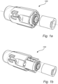
- the coupling device 100 is provided for the transfer of a fluid through the coupling device 100 when the coupling device 100 is in its connected state.
- a connection of the coupling device 100 has been initiated, which will be described in more detail in the following text and associated figures.
- Fig. 1b a disconnection of the coupling device 100 has been initiated.
- the coupling device 100 becomes disconnected (detached), whereby the transfer of fluid through the coupling device 100 is interrupted.
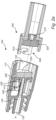
- the coupling device 100 further comprises a second housing 300 which in the disconnected state of the coupling device 100 is separated from the first housing 110 (and according to examples, also from the third housing 200) of the coupling device 100.
- the second housing 300 comprises a channel 310 which is arranged through the second housing 300.
- the third housing 200 further comprises a second sealing element 320 which is arranged to seal the second channel 310.
- the first sealing element 220 seals the tube 140 such that there is no passage of fluid through the third housing 200 or first housing 110.
- the second sealing element 320 seals the second channel 310 such that there is no passage of fluid through the second housing 300.
- the second housing 300 is insertable into the first housing 110 via the second opening 130 of the first housing 110.
- the first housing 110 is able to receive the second housing 300 via the second opening 130 thereof and accommodate the second housing 300 within the first housing 110.
- the first housing 110 and the second housing 300 may have elliptic cross-sections, whereas the third housing 200 may have a circular cross-section. It will be appreciated that the provision of elliptic cross-sections may facilitate the coupling between the housings.
- the second housing 300 may be connected to the third housing 200 by a relative arrangement of 0° or 180° between the second housing 300 and the third housing 200.
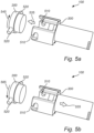
- Fig. 3b is a schematic, cross-sectional view of a portion of a coupling device 100 at a second stage of a disconnection of the coupling device 100 according to an example of the present invention.
- the tube 140 is retracted through the first sealing element 220.
- the tube 140 in Fig. 3b has been retracted through the second sealing element 320 such that the end portion 380 of the tube 140 is in close vicinity of the (face of the) second sealing element 320.
- the tube 140, the first sealing element 220 and the second sealing element 320 are configured to define a second space 410 at the end portion 380 of the tube 140.
- the volume and/or shape of the second space 410 may be dependent on one or more properties of the first sealing element 220 and/or the tube 140, e.g. the material of the first sealing element 220, the material and/or shape of the tube 140, etc.
- the volume and/or shape of the second space 410 may be dependent on the friction between the first sealing element 220 and the tube 140.
- the first space 400 as defined by the tube 140 and the second sealing element 320 in Fig. 3a has collapsed upon the retraction of the tube 140 in Fig. 3b .
- the second sealing element 320 has retained its unbiased, original state and the fluid which was present in the first space 400 in Fig. 3a has entered (has been released into) the second space 410.
- antimicrobial peptides have a broad spectrum of activity and are effective against drug-resistant pathogens.
- lactoferrin present in breast milk
- lactoferricin lactoferricin
- AMC-109 AMC-109 may retain and amplify the antimicrobial properties characteristic of the natural peptides while gaining the properties required of an industrially applicable product such as extended stability against metabolic degradation and ease of manufacture.
- the fluid which has been released from the first space 400 and has entered the second space 410 comes into contact with at least a portion of the antimicrobial coating 330a of the first sealing element 220 and/or at least a portion of the antimicrobial coating 330b of the second sealing element 320.
- Figs. 4a-c are schematic, cross-sectional views of portions of a coupling device 100 according to exemplifying embodiments of the present invention. It should be noted that features and/or references of the coupling device 100 with respect to the coupling device 100 as described by Figs. 2a-d have been removed for simplicity, and it is referred to Figs. 2a-d for an increased understanding of the operation of the coupling device 100. It will be appreciated that Figs. 4a-c disclose exemplifying and momentary stages of a connection and disconnection of a coupling device 100 for an increased understanding of the operation of the coupling device 100 according to the present invention.
- Fig. 4b is a schematic, cross-sectional view of a portion of a coupling device 100 at a first stage of a disconnection of the coupling device 100 according to the present invention.
- the tube 140 is retracted through the first and second sealing elements 220, 320.
- the tube 140 which in Fig. 2d was in fluid contact with the channel 310 for a transfer of fluid through the coupling device 100 in the second stage of the connection of the coupling device 100, has been retracted such that an end portion 380 of the tube 140 is enclosed by the second sealing element 320.
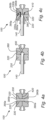
- the second locking element 520 Upon movement of the second housing 300 towards the third housing 200, as indicated by arrow 535, the second locking element 520 is configured to rotate, as indicated by arrow 545, as the result of the second locking element 520 being guided by a groove in the first housing (not shown).
- the second locking element 520 is hereby rotated with respect to the first locking element 510 for mating engagement with the first locking element 510 such that the second housing 300 and the third housing 200 become connected in the second position of the second housing 300.
- the third housing 200 in the second position, is releasably connected to the first housing 110 via the at least one groove 410 (see Fig. 2a ) and the second locking element 520.
- the coupling device 100 furthermore may comprise an alarm arrangement (not shown).
- the alarm arrangement may be configured to generate an alarm in case the coupling device 100 is disconnected.
- the alarm may for example comprise a visual alarm and/or an audible alarm.
- the alarm may be coupled (wirelessly or by wire) to any other equipment used by the medical staff for monitoring the patient(s).
Landscapes
- Health & Medical Sciences (AREA)
- Engineering & Computer Science (AREA)
- Heart & Thoracic Surgery (AREA)
- General Engineering & Computer Science (AREA)
- Hematology (AREA)
- Pulmonology (AREA)
- Anesthesiology (AREA)
- Biomedical Technology (AREA)
- Life Sciences & Earth Sciences (AREA)
- Animal Behavior & Ethology (AREA)
- General Health & Medical Sciences (AREA)
- Public Health (AREA)
- Veterinary Medicine (AREA)
- Mechanical Engineering (AREA)
- Epidemiology (AREA)
- Infusion, Injection, And Reservoir Apparatuses (AREA)
Priority Applications (5)
| Application Number | Priority Date | Filing Date | Title |
|---|---|---|---|
| EP21186504.3A EP4122525B1 (en) | 2021-07-19 | 2021-07-19 | Coupling device with coating |
| US18/580,907 US12442476B2 (en) | 2021-07-19 | 2022-06-30 | Coupling device with coating |
| CN202280049051.6A CN117677421A (zh) | 2021-07-19 | 2022-06-30 | 具有涂层的联接装置 |
| PCT/EP2022/068155 WO2023001524A1 (en) | 2021-07-19 | 2022-06-30 | Coupling device with coating |
| JP2024501652A JP2024525711A (ja) | 2021-07-19 | 2022-06-30 | コーティング付き結合デバイス |
Applications Claiming Priority (1)
| Application Number | Priority Date | Filing Date | Title |
|---|---|---|---|
| EP21186504.3A EP4122525B1 (en) | 2021-07-19 | 2021-07-19 | Coupling device with coating |
Publications (2)
| Publication Number | Publication Date |
|---|---|
| EP4122525A1 EP4122525A1 (en) | 2023-01-25 |
| EP4122525B1 true EP4122525B1 (en) | 2025-04-09 |
Family
ID=76971788
Family Applications (1)
| Application Number | Title | Priority Date | Filing Date |
|---|---|---|---|
| EP21186504.3A Active EP4122525B1 (en) | 2021-07-19 | 2021-07-19 | Coupling device with coating |
Country Status (5)
| Country | Link |
|---|---|
| US (1) | US12442476B2 (https=) |
| EP (1) | EP4122525B1 (https=) |
| JP (1) | JP2024525711A (https=) |
| CN (1) | CN117677421A (https=) |
| WO (1) | WO2023001524A1 (https=) |
Families Citing this family (1)
| Publication number | Priority date | Publication date | Assignee | Title |
|---|---|---|---|---|
| WO2025144732A1 (en) * | 2023-12-28 | 2025-07-03 | Luminoah, Inc. | Separable bi-directional check valve assembly |
Family Cites Families (9)
| Publication number | Priority date | Publication date | Assignee | Title |
|---|---|---|---|---|
| US4256106A (en) * | 1979-04-30 | 1981-03-17 | Becton, Dickinson And Company | Resealable device |
| US5509912A (en) * | 1994-10-24 | 1996-04-23 | Vlv Associates | Connector |
| US6181287B1 (en) * | 1997-03-10 | 2001-01-30 | Precision Dynamics Corporation | Reactively coupled elements in circuits on flexible substrates |
| US7232419B2 (en) * | 2002-02-11 | 2007-06-19 | Baxter International Inc. | Enclosure with cam action snap release |
| US7198611B2 (en) * | 2002-02-11 | 2007-04-03 | Baxter International Inc. | Dialysis connector and cap having an integral disinfectant |
| US8512294B2 (en) * | 2006-07-28 | 2013-08-20 | Becton, Dickinson And Company | Vascular access device antimicrobial materials and solutions |
| SE1651467A1 (sv) * | 2016-11-09 | 2018-05-10 | Tada Medical Ab | Coupling device |
| JP7163617B2 (ja) * | 2018-05-22 | 2022-11-01 | 株式会社ジェイ・エム・エス | レバーロック式オスコネクタ |
| CN213312923U (zh) * | 2020-06-23 | 2021-06-01 | 南方医科大学珠江医院 | 一体化一次性使用带固定装置无菌连接头 |
-
2021
- 2021-07-19 EP EP21186504.3A patent/EP4122525B1/en active Active
-
2022
- 2022-06-30 JP JP2024501652A patent/JP2024525711A/ja active Pending
- 2022-06-30 CN CN202280049051.6A patent/CN117677421A/zh active Pending
- 2022-06-30 US US18/580,907 patent/US12442476B2/en active Active
- 2022-06-30 WO PCT/EP2022/068155 patent/WO2023001524A1/en not_active Ceased
Also Published As
| Publication number | Publication date |
|---|---|
| US20240230000A1 (en) | 2024-07-11 |
| WO2023001524A1 (en) | 2023-01-26 |
| CN117677421A (zh) | 2024-03-08 |
| JP2024525711A (ja) | 2024-07-12 |
| EP4122525A1 (en) | 2023-01-25 |
| US12442476B2 (en) | 2025-10-14 |
Similar Documents
| Publication | Publication Date | Title |
|---|---|---|
| EP3538201B1 (en) | Coupling device | |
| EP3960229B1 (en) | Coupling device | |
| US9851037B2 (en) | Fluid connector and method for making sealed fluid connections | |
| EP0956088B1 (en) | Positive flow valve | |
| US20060129109A1 (en) | Reconnectable disconnect device for fluid transfer line | |
| US20050090805A1 (en) | Reconnectable disconnect device for fluid transfer line | |
| EP4122525B1 (en) | Coupling device with coating | |
| KR20220054416A (ko) | 분리시에 시일링이 자동적으로 이루어지는 의료용 커넥터 | |
| US20240204452A1 (en) | Connector coupling assembly | |
| EP4122524A1 (en) | Coupling device for transferring fluid | |
| CA3042594C (en) | Coupling device | |
| WO2014116883A1 (en) | Device for improved prevention of infectious contamination in intravenous ("iv") components |
Legal Events
| Date | Code | Title | Description |
|---|---|---|---|
| PUAI | Public reference made under article 153(3) epc to a published international application that has entered the european phase |
Free format text: ORIGINAL CODE: 0009012 |
|
| STAA | Information on the status of an ep patent application or granted ep patent |
Free format text: STATUS: THE APPLICATION HAS BEEN PUBLISHED |
|
| AK | Designated contracting states |
Kind code of ref document: A1 Designated state(s): AL AT BE BG CH CY CZ DE DK EE ES FI FR GB GR HR HU IE IS IT LI LT LU LV MC MK MT NL NO PL PT RO RS SE SI SK SM TR |
|
| RAP3 | Party data changed (applicant data changed or rights of an application transferred) |
Owner name: TADA GROUP AB |
|
| STAA | Information on the status of an ep patent application or granted ep patent |
Free format text: STATUS: REQUEST FOR EXAMINATION WAS MADE |
|
| 17P | Request for examination filed |
Effective date: 20230531 |
|
| RBV | Designated contracting states (corrected) |
Designated state(s): AL AT BE BG CH CY CZ DE DK EE ES FI FR GB GR HR HU IE IS IT LI LT LU LV MC MK MT NL NO PL PT RO RS SE SI SK SM TR |
|
| RAP3 | Party data changed (applicant data changed or rights of an application transferred) |
Owner name: INTERLINKED AB |
|
| GRAP | Despatch of communication of intention to grant a patent |
Free format text: ORIGINAL CODE: EPIDOSNIGR1 |
|
| STAA | Information on the status of an ep patent application or granted ep patent |
Free format text: STATUS: GRANT OF PATENT IS INTENDED |
|
| INTG | Intention to grant announced |
Effective date: 20241209 |
|
| GRAS | Grant fee paid |
Free format text: ORIGINAL CODE: EPIDOSNIGR3 |
|
| GRAA | (expected) grant |
Free format text: ORIGINAL CODE: 0009210 |
|
| STAA | Information on the status of an ep patent application or granted ep patent |
Free format text: STATUS: THE PATENT HAS BEEN GRANTED |
|
| AK | Designated contracting states |
Kind code of ref document: B1 Designated state(s): AL AT BE BG CH CY CZ DE DK EE ES FI FR GB GR HR HU IE IS IT LI LT LU LV MC MK MT NL NO PL PT RO RS SE SI SK SM TR |
|
| REG | Reference to a national code |
Ref country code: GB Ref legal event code: FG4D |
|
| REG | Reference to a national code |
Ref country code: CH Ref legal event code: EP |
|
| REG | Reference to a national code |
Ref country code: DE Ref legal event code: R096 Ref document number: 602021028796 Country of ref document: DE |
|
| REG | Reference to a national code |
Ref country code: IE Ref legal event code: FG4D |
|
| PGFP | Annual fee paid to national office [announced via postgrant information from national office to epo] |
Ref country code: GB Payment date: 20250613 Year of fee payment: 5 |
|
| PGFP | Annual fee paid to national office [announced via postgrant information from national office to epo] |
Ref country code: NO Payment date: 20250618 Year of fee payment: 5 |
|
| PGFP | Annual fee paid to national office [announced via postgrant information from national office to epo] |
Ref country code: FR Payment date: 20250613 Year of fee payment: 5 |
|
| REG | Reference to a national code |
Ref country code: NL Ref legal event code: MP Effective date: 20250409 |
|
| PG25 | Lapsed in a contracting state [announced via postgrant information from national office to epo] |
Ref country code: NL Free format text: LAPSE BECAUSE OF FAILURE TO SUBMIT A TRANSLATION OF THE DESCRIPTION OR TO PAY THE FEE WITHIN THE PRESCRIBED TIME-LIMIT Effective date: 20250409 |
|
| REG | Reference to a national code |
Ref country code: AT Ref legal event code: MK05 Ref document number: 1783017 Country of ref document: AT Kind code of ref document: T Effective date: 20250409 |
|
| PG25 | Lapsed in a contracting state [announced via postgrant information from national office to epo] |
Ref country code: ES Free format text: LAPSE BECAUSE OF FAILURE TO SUBMIT A TRANSLATION OF THE DESCRIPTION OR TO PAY THE FEE WITHIN THE PRESCRIBED TIME-LIMIT Effective date: 20250409 Ref country code: FI Free format text: LAPSE BECAUSE OF FAILURE TO SUBMIT A TRANSLATION OF THE DESCRIPTION OR TO PAY THE FEE WITHIN THE PRESCRIBED TIME-LIMIT Effective date: 20250409 Ref country code: PT Free format text: LAPSE BECAUSE OF FAILURE TO SUBMIT A TRANSLATION OF THE DESCRIPTION OR TO PAY THE FEE WITHIN THE PRESCRIBED TIME-LIMIT Effective date: 20250811 |
|
| PGFP | Annual fee paid to national office [announced via postgrant information from national office to epo] |
Ref country code: DE Payment date: 20250617 Year of fee payment: 5 |
|
| REG | Reference to a national code |
Ref country code: LT Ref legal event code: MG9D |
|
| PG25 | Lapsed in a contracting state [announced via postgrant information from national office to epo] |
Ref country code: GR Free format text: LAPSE BECAUSE OF FAILURE TO SUBMIT A TRANSLATION OF THE DESCRIPTION OR TO PAY THE FEE WITHIN THE PRESCRIBED TIME-LIMIT Effective date: 20250710 |
|
| PG25 | Lapsed in a contracting state [announced via postgrant information from national office to epo] |
Ref country code: PL Free format text: LAPSE BECAUSE OF FAILURE TO SUBMIT A TRANSLATION OF THE DESCRIPTION OR TO PAY THE FEE WITHIN THE PRESCRIBED TIME-LIMIT Effective date: 20250409 |
|
| PGFP | Annual fee paid to national office [announced via postgrant information from national office to epo] |
Ref country code: IT Payment date: 20250616 Year of fee payment: 5 |
|
| PG25 | Lapsed in a contracting state [announced via postgrant information from national office to epo] |
Ref country code: BG Free format text: LAPSE BECAUSE OF FAILURE TO SUBMIT A TRANSLATION OF THE DESCRIPTION OR TO PAY THE FEE WITHIN THE PRESCRIBED TIME-LIMIT Effective date: 20250409 |
|
| PG25 | Lapsed in a contracting state [announced via postgrant information from national office to epo] |
Ref country code: HR Free format text: LAPSE BECAUSE OF FAILURE TO SUBMIT A TRANSLATION OF THE DESCRIPTION OR TO PAY THE FEE WITHIN THE PRESCRIBED TIME-LIMIT Effective date: 20250409 |
|
| PG25 | Lapsed in a contracting state [announced via postgrant information from national office to epo] |
Ref country code: AT Free format text: LAPSE BECAUSE OF FAILURE TO SUBMIT A TRANSLATION OF THE DESCRIPTION OR TO PAY THE FEE WITHIN THE PRESCRIBED TIME-LIMIT Effective date: 20250409 |
|
| PG25 | Lapsed in a contracting state [announced via postgrant information from national office to epo] |
Ref country code: RS Free format text: LAPSE BECAUSE OF FAILURE TO SUBMIT A TRANSLATION OF THE DESCRIPTION OR TO PAY THE FEE WITHIN THE PRESCRIBED TIME-LIMIT Effective date: 20250709 |
|
| PG25 | Lapsed in a contracting state [announced via postgrant information from national office to epo] |
Ref country code: IS Free format text: LAPSE BECAUSE OF FAILURE TO SUBMIT A TRANSLATION OF THE DESCRIPTION OR TO PAY THE FEE WITHIN THE PRESCRIBED TIME-LIMIT Effective date: 20250809 |
|
| PG25 | Lapsed in a contracting state [announced via postgrant information from national office to epo] |
Ref country code: LV Free format text: LAPSE BECAUSE OF FAILURE TO SUBMIT A TRANSLATION OF THE DESCRIPTION OR TO PAY THE FEE WITHIN THE PRESCRIBED TIME-LIMIT Effective date: 20250409 |
|
| REG | Reference to a national code |
Ref country code: DE Ref legal event code: R097 Ref document number: 602021028796 Country of ref document: DE |
|
| PG25 | Lapsed in a contracting state [announced via postgrant information from national office to epo] |
Ref country code: SM Free format text: LAPSE BECAUSE OF FAILURE TO SUBMIT A TRANSLATION OF THE DESCRIPTION OR TO PAY THE FEE WITHIN THE PRESCRIBED TIME-LIMIT Effective date: 20250409 Ref country code: DK Free format text: LAPSE BECAUSE OF FAILURE TO SUBMIT A TRANSLATION OF THE DESCRIPTION OR TO PAY THE FEE WITHIN THE PRESCRIBED TIME-LIMIT Effective date: 20250409 |
|
| PG25 | Lapsed in a contracting state [announced via postgrant information from national office to epo] |
Ref country code: CZ Free format text: LAPSE BECAUSE OF FAILURE TO SUBMIT A TRANSLATION OF THE DESCRIPTION OR TO PAY THE FEE WITHIN THE PRESCRIBED TIME-LIMIT Effective date: 20250409 |
|
| PG25 | Lapsed in a contracting state [announced via postgrant information from national office to epo] |
Ref country code: EE Free format text: LAPSE BECAUSE OF FAILURE TO SUBMIT A TRANSLATION OF THE DESCRIPTION OR TO PAY THE FEE WITHIN THE PRESCRIBED TIME-LIMIT Effective date: 20250409 |
|
| PG25 | Lapsed in a contracting state [announced via postgrant information from national office to epo] |
Ref country code: SK Free format text: LAPSE BECAUSE OF FAILURE TO SUBMIT A TRANSLATION OF THE DESCRIPTION OR TO PAY THE FEE WITHIN THE PRESCRIBED TIME-LIMIT Effective date: 20250409 |
|
| PG25 | Lapsed in a contracting state [announced via postgrant information from national office to epo] |
Ref country code: RO Free format text: LAPSE BECAUSE OF FAILURE TO SUBMIT A TRANSLATION OF THE DESCRIPTION OR TO PAY THE FEE WITHIN THE PRESCRIBED TIME-LIMIT Effective date: 20250409 |
|
| PLBE | No opposition filed within time limit |
Free format text: ORIGINAL CODE: 0009261 |
|
| STAA | Information on the status of an ep patent application or granted ep patent |
Free format text: STATUS: NO OPPOSITION FILED WITHIN TIME LIMIT |
|
| REG | Reference to a national code |
Ref country code: CH Ref legal event code: L10 Free format text: ST27 STATUS EVENT CODE: U-0-0-L10-L00 (AS PROVIDED BY THE NATIONAL OFFICE) Effective date: 20260218 |
|
| REG | Reference to a national code |
Ref country code: CH Ref legal event code: H13 Free format text: ST27 STATUS EVENT CODE: U-0-0-H10-H13 (AS PROVIDED BY THE NATIONAL OFFICE) Effective date: 20260224 |
|
| PG25 | Lapsed in a contracting state [announced via postgrant information from national office to epo] |
Ref country code: LU Free format text: LAPSE BECAUSE OF NON-PAYMENT OF DUE FEES Effective date: 20250719 |
|
| 26N | No opposition filed |
Effective date: 20260112 |
|
| REG | Reference to a national code |
Ref country code: BE Ref legal event code: MM Effective date: 20250731 |
|
| PG25 | Lapsed in a contracting state [announced via postgrant information from national office to epo] |
Ref country code: BE Free format text: LAPSE BECAUSE OF NON-PAYMENT OF DUE FEES Effective date: 20250731 |
|
| PG25 | Lapsed in a contracting state [announced via postgrant information from national office to epo] |
Ref country code: CH Free format text: LAPSE BECAUSE OF NON-PAYMENT OF DUE FEES Effective date: 20250731 |