EP4121708B1 - Wärmetauscher für ein kraftfahrzeug - Google Patents
Wärmetauscher für ein kraftfahrzeug Download PDFInfo
- Publication number
- EP4121708B1 EP4121708B1 EP21711925.4A EP21711925A EP4121708B1 EP 4121708 B1 EP4121708 B1 EP 4121708B1 EP 21711925 A EP21711925 A EP 21711925A EP 4121708 B1 EP4121708 B1 EP 4121708B1
- Authority
- EP
- European Patent Office
- Prior art keywords
- contact
- tubes
- transverse
- tube
- heat exchanger
- Prior art date
- Legal status (The legal status is an assumption and is not a legal conclusion. Google has not performed a legal analysis and makes no representation as to the accuracy of the status listed.)
- Active
Links
Images


Classifications
-
- F—MECHANICAL ENGINEERING; LIGHTING; HEATING; WEAPONS; BLASTING
- F28—HEAT EXCHANGE IN GENERAL
- F28D—HEAT-EXCHANGE APPARATUS, NOT PROVIDED FOR IN ANOTHER SUBCLASS, IN WHICH THE HEAT-EXCHANGE MEDIA DO NOT COME INTO DIRECT CONTACT
- F28D7/00—Heat-exchange apparatus having stationary tubular conduit assemblies for both heat-exchange media, the media being in contact with different sides of a conduit wall
- F28D7/16—Heat-exchange apparatus having stationary tubular conduit assemblies for both heat-exchange media, the media being in contact with different sides of a conduit wall the conduits being arranged in parallel spaced relation
- F28D7/1684—Heat-exchange apparatus having stationary tubular conduit assemblies for both heat-exchange media, the media being in contact with different sides of a conduit wall the conduits being arranged in parallel spaced relation the conduits having a non-circular cross-section
-
- F—MECHANICAL ENGINEERING; LIGHTING; HEATING; WEAPONS; BLASTING
- F02—COMBUSTION ENGINES; HOT-GAS OR COMBUSTION-PRODUCT ENGINE PLANTS
- F02B—INTERNAL-COMBUSTION PISTON ENGINES; COMBUSTION ENGINES IN GENERAL
- F02B29/00—Engines characterised by provision for charging or scavenging not provided for in groups F02B25/00, F02B27/00 or F02B33/00 - F02B39/00; Details thereof
- F02B29/04—Cooling of air intake supply
- F02B29/045—Constructional details of the heat exchangers, e.g. pipes, plates, ribs, insulation, materials, or manufacturing and assembly
-
- F—MECHANICAL ENGINEERING; LIGHTING; HEATING; WEAPONS; BLASTING
- F28—HEAT EXCHANGE IN GENERAL
- F28F—DETAILS OF HEAT-EXCHANGE AND HEAT-TRANSFER APPARATUS, OF GENERAL APPLICATION
- F28F9/00—Casings; Header boxes; Auxiliary supports for elements; Auxiliary members within casings
- F28F9/02—Header boxes; End plates
- F28F9/0219—Arrangements for sealing end plates into casing or header box; Header box sub-elements
- F28F9/0224—Header boxes formed by sealing end plates into covers
-
- F—MECHANICAL ENGINEERING; LIGHTING; HEATING; WEAPONS; BLASTING
- F28—HEAT EXCHANGE IN GENERAL
- F28F—DETAILS OF HEAT-EXCHANGE AND HEAT-TRANSFER APPARATUS, OF GENERAL APPLICATION
- F28F9/00—Casings; Header boxes; Auxiliary supports for elements; Auxiliary members within casings
- F28F9/02—Header boxes; End plates
- F28F9/04—Arrangements for sealing elements into header boxes or end plates
- F28F9/16—Arrangements for sealing elements into header boxes or end plates by permanent joints, e.g. by rolling
- F28F9/18—Arrangements for sealing elements into header boxes or end plates by permanent joints, e.g. by rolling by welding
- F28F9/182—Arrangements for sealing elements into header boxes or end plates by permanent joints, e.g. by rolling by welding the heat-exchange conduits having ends with a particular shape, e.g. deformed; the heat-exchange conduits or end plates having supplementary joining means, e.g. abutments
-
- F—MECHANICAL ENGINEERING; LIGHTING; HEATING; WEAPONS; BLASTING
- F28—HEAT EXCHANGE IN GENERAL
- F28D—HEAT-EXCHANGE APPARATUS, NOT PROVIDED FOR IN ANOTHER SUBCLASS, IN WHICH THE HEAT-EXCHANGE MEDIA DO NOT COME INTO DIRECT CONTACT
- F28D21/00—Heat-exchange apparatus not covered by any of the groups F28D1/00 - F28D20/00
- F28D2021/0019—Other heat exchangers for particular applications; Heat exchange systems not otherwise provided for
- F28D2021/008—Other heat exchangers for particular applications; Heat exchange systems not otherwise provided for for vehicles
- F28D2021/0082—Charged air coolers
-
- F—MECHANICAL ENGINEERING; LIGHTING; HEATING; WEAPONS; BLASTING
- F28—HEAT EXCHANGE IN GENERAL
- F28F—DETAILS OF HEAT-EXCHANGE AND HEAT-TRANSFER APPARATUS, OF GENERAL APPLICATION
- F28F2275/00—Fastening; Joining
- F28F2275/06—Fastening; Joining by welding
-
- Y—GENERAL TAGGING OF NEW TECHNOLOGICAL DEVELOPMENTS; GENERAL TAGGING OF CROSS-SECTIONAL TECHNOLOGIES SPANNING OVER SEVERAL SECTIONS OF THE IPC; TECHNICAL SUBJECTS COVERED BY FORMER USPC CROSS-REFERENCE ART COLLECTIONS [XRACs] AND DIGESTS
- Y02—TECHNOLOGIES OR APPLICATIONS FOR MITIGATION OR ADAPTATION AGAINST CLIMATE CHANGE
- Y02T—CLIMATE CHANGE MITIGATION TECHNOLOGIES RELATED TO TRANSPORTATION
- Y02T10/00—Road transport of goods or passengers
- Y02T10/10—Internal combustion engine [ICE] based vehicles
- Y02T10/12—Improving ICE efficiencies
Definitions
- the invention relates to a heat exchanger for a motor vehicle and it relates more particularly to a heat exchanger capable of cooling the air supplied to the vehicle engine.
- a heat exchanger comprising the characteristics of the preamble of claim 1 is known from FR 3 030 709 .
- Such an exchanger may comprise an intake manifold and a distribution manifold framing a heat exchange bundle capable of channeling fluids and configured to allow heat exchange between the fluids when they cross in the heat exchanger.
- the heat exchange bundle comprises tubes in which a first fluid circulates through the heat exchanger, the second fluid being guided to circulate between the tubes. It is thus at the level of these tubes that the gases are cooled, in particular by heat exchange with a cooling fluid which is advantageously a heat transfer fluid.
- the cooling fluid circulates through the heat exchange bundle, between the tubes, and thus contributes to the cooling of the gases circulating in the tubes.
- the heat exchange bundle thus has a sealed internal volume in which the cooling fluid circulates. It is known to delimit this internal volume by three elements, namely by the intake and distribution manifolds, by a first and a last tube extending at the ends of the heat exchange bundle and by a casing surrounding the tubes of the heat exchanger.
- connection areas between the various components delimiting the internal volume of the heat exchange bundle, in particular to prevent coolant from leaking from the heat exchanger at these connection areas.
- the invention thus relates to a heat exchanger whose function is to cool a first fluid, in particular using a second fluid.
- the intake manifold receives the first fluid, this fluid then passing through the heat exchange bundle towards the distribution manifold.
- the first fluid is cooled by a second fluid, the cooled first fluid then arriving at the distribution manifold.
- the second fluid is guided into circulation within the heat exchange bundle by means of the heat exchange bundle casing. Therefore, the heat exchanger must be sealed to prevent leakage of the second fluid from the heat exchanger.
- Surface contact is understood to mean a contact that extends at least in one plane, this plane being here a plane substantially perpendicular to the longitudinal direction.
- the casing is thus in contact with at least one of the collectors, and advantageously both collectors, in a plane perpendicular to the longitudinal direction.
- the straight-edged end of the casing allows, when mounting the collector plate on the heat exchange bundle, to push the collector plate all the way to the stop and thus to ensure that the collector plate is as close as possible to the casing before the brazing operation.
- the envelope is also in planar surface contact with the at least one collector plate in a plane parallel to the longitudinal direction.
- the tubes are arranged successively next to each other in the transverse direction and in which the envelope comprises at least one transverse wall which extends in this transverse direction while being in contact with each of the tubes, the surface contact between collector plate and tube being formed at the longitudinal end of this transverse wall.
- a protrusion is an extension of the casing from one of its longitudinal ends.
- the main function of the protrusion is to reinforce the sealing function of the casing, in particular by positioning itself in a space where the second fluid can leak.
- the protrusion is configured to be positioned at one of the contact zones of the casing with the intake and/or distribution manifold.
- the outgrowth can be a single piece with the envelope.
- single piece means that the outgrowth and the envelope can only be separated by the destruction of one of the two elements.
- the protrusion extends at least partially one of the longitudinal ends of the casing along the longitudinal direction, but the protrusion may also extend along another direction.
- the protrusion may extend along a direction parallel to the direction in which the plurality of tubes are aligned.
- the perforated wall is stamped locally, around each of the through openings, so as to present a rolled end edge forming a projecting border of the perforated wall and increasing the contact surface with the tubes.
- the envelope has a first longitudinal end with a straight edge in contact with the first collector plate at a first contact zone and a second longitudinal end with a straight edge in contact with the second collector plate at a second contact zone.
- Each of the longitudinal ends of the casing is in contact with either the collector plate associated with the intake manifold or the collector plate associated with the distribution manifold, thereby forming a first contact zone at the intake manifold and a second contact zone at the distribution manifold.
- At least one of the contact zones of the envelope is a surface contact in a plane perpendicular to the longitudinal direction.
- the first contact zone or the second contact zone reproduces a surface contact in a plane perpendicular to the longitudinal direction in accordance with the invention.
- each contact zone of the envelope with the intake manifold and the distribution manifold is a surface contact in a plane perpendicular to the longitudinal direction.
- variants of the invention may be combined with each other in various combinations, provided that they are not incompatible or mutually exclusive.
- variants of the invention may be conceived comprising only a selection of features described below in isolation from the other features described, if this selection of features is sufficient to confer a technical advantage and/or to differentiate the invention from the prior art.
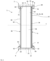
- FIG. 1 illustrates a heat exchanger 1 according to the invention, suitable for equipping a motor vehicle and which can in particular constitute a cooling radiator for an engine or a heating radiator for the passenger compartment of this vehicle.
- the heat exchanger 1 generally takes the form of a rectangular parallelepiped and comprises at least one intake manifold, not shown here, and capable of being fixed to a first collector plate 2, a distribution manifold, not shown here, and capable of being fixed to a second collector plate 4, and a heat exchange bundle 6 extending between the intake manifold and the distribution manifold along a longitudinal direction A.
- the bundle 6 is in particular configured to allow heat exchange between a first fluid and a second fluid.
- the first fluid may, for example, be supercharging air intended to supply the vehicle's engine
- the second fluid may be a coolant or air depending on whether the heat exchanger is of the air-water or air-air type.
- the first collector plate 2 and the second collector plate 4 each represent an opposite face of the rectangular parallelepiped, the heat exchange bundle 6 being arranged between these collector plates and formed, as will be described below, by an external envelope and a plurality of tubes arranged in parallel with each other inside this envelope.
- the heat exchange bundle is such that the first fluid is caused to circulate inside each of the tubes and the second fluid is caused to circulate between the tubes, the heat exchange taking place from one fluid to the other at the level of the tubes.
- the first collector plate 2 and the second collector plate 4 are symmetrical to each other with respect to the heat exchange bundle 6 and to the longitudinal direction A. In this way, a characteristic described for one collector plate will also be applicable to the other collector plate, whether the latter is intended to be secured to the intake manifold or to the distribution manifold.
- the general term “collector plate 2, 4” will refer indifferently to the first collector plate 2 and to the second collector plate 4 in the remainder of the description.
- the collector plate 2, 4 extends mainly in a plane perpendicular to the longitudinal direction A, a main dimension of the collector plate 2, 4 being measured along a transverse direction B perpendicular to the longitudinal direction A.
- the collector plate 2, 4 comprises an openwork wall 8 delimited peripherally by a frame 10. More particularly, the collector plate comprises a plurality of bars arranged parallel to each other, perpendicular to the transverse direction B, extending between two opposite edges of the frame so as to define a plurality of through openings 12 through which a fluid, and in particular supercharging air intended to supply the engine of the vehicle, can circulate.
- These through openings 12 are here represented in an elongated shape, such as a rectangle for example, the largest dimension of which is measured along a vertical direction C perpendicular to the longitudinal directions A and transverse directions B.
- Each through opening 12 is sized to receive the end of one of the tubes forming part of the heat exchange bundle 6 as they will be described below. It is thus understood that the fluid brought to pass through the collector and the corresponding through openings 12 comes from the tubes or is directed inside the tubes, depending on whether the collector is an inlet or outlet collector.
- the frame 10 forms an extension of the periphery of the perforated wall 8 along the longitudinal direction A, over the entire periphery of this perforated wall 8. More particularly, the frame 10 comprises a first portion 21 which directly extends the perforated wall and which extends towards the inside of the heat exchanger, that is to say towards the heat exchange bundle 6, forming a bowl surrounding the perforated wall, and it also comprises a second portion 22 which directly extends the first portion 21 and which extends longitudinally opposite the heat exchange bundle while having a free end edge. The free end edge of the second portion 22 is configured to cooperate with the aforementioned power supply circuit and/or the motor while the first portion 21 is configured to be in contact with the heat exchange bundle 6.
- the heat exchange bundle 6 of the heat exchanger 1 comprises at least a plurality of tubes 24 and a casing 38.
- the tubes 24 are arranged parallel to each other, each of the tubes 24 extending longitudinally between the intake manifold and the first collector plate 2 and the distribution manifold and the second collector plate 4 through the heat exchange bundle 6.
- the tubes are arranged successively one after the other so that a first tube 26 can be distinguished, arranged at one transverse end of this plurality of tubes, and a last tube 28, arranged at the opposite transverse end of this plurality of tubes.
- Each tube 24 extends longitudinally between a first end 30 and a second end 32 and is arranged in the heat exchange bundle 6 so that the first end 30 is in contact with the first collector plate 2 and the second end 32 is in contact with the second collector plate 4.
- Each end 30, 32 of these tubes 24 protrudes from the corresponding through opening 12 so that the tubes 24 thus open into the intake or distribution manifold and allow the passage of fluid between these collectors and the heat exchange bundle.
- Three first ends 30 are visible on the Figure 1 , the other tubes not having been shown to make visible the position of the tubes through the collector plate.
- Each tube 24 extends along the longitudinal direction A, between a through opening 12 of the first collector plate 2 and a corresponding through opening of the second collector plate of the distribution manifold 4.
- the plurality of tubes 24 generally comprises as many tubes 24 as the number of through openings 12 of the collector plates 2, 4, each tube 24 connecting a through opening 12 of the first collector plate 2 to the corresponding through opening 12 of the second collector plate 4.
- Each tube 24 has a shape similar to that of the other tubes 24, namely here the shape of a flat tube, a section of each tube 24 corresponding to the section of a through opening 12 of the collector plates 2, 4. More precisely, the section of each tube 24 has a generally rectangular shape, the largest dimension of which is measured along the vertical direction C. In this way, each tube 24 has two end faces 34 opposite here vertically with respect to each other and two main faces 36 connecting the end faces 34.
- the envelope 38 is intended to surround the plurality of tubes 24 and to seal the area defining the heat exchange bundle 6. More particularly, the envelope 38 comprises two side walls 40, of which only one of the two side walls 40 is visible on the Figure 2 , and two transverse walls 42, 44 which each extend longitudinally between the intake manifold and the first collector plate 2 on the one hand and the distribution manifold and the second collector plate 4 on the other hand.
- Each of the side walls 40 extends in a plane parallel to the longitudinal A and vertical C directions, one of these side walls 40 being arranged on a main external face of the last tube 28 of the plurality of tubes 24, while the other side wall is arranged on a main external face of the first tube 26 of the plurality of tubes 24. It is understood that the main external face of the first tube and the main external face of the last tube are turned away from each other, towards the outside of the heat exchange bundle 6, so that the side walls 40 of the casing 38 transversely frame the plurality of tubes 24.
- the transverse walls 42, 44 each extend in a plane parallel to the longitudinal directions A and transverse directions B. These transverse walls 42, 44 extend between the collector plates 2, 4 along the longitudinal direction A and between the side walls 40 along the transverse direction B.
- the transverse walls 42, 44 vertically frame the plurality of tubes 24.
- Each transverse wall 42, 44 comprises a flat portion intended to be pressed against the end faces 34 of the tubes and a stamped portion 48 forming a fluid circulation channel which extends mainly perpendicular to the direction of elongation of the tubes, namely here the longitudinal direction.
- This stamped portion forms a portion bulging towards the outside of the heat exchange bundle 6 and it has a fluid inlet or outlet 46 equipped with a circular orifice 50 through which the fluid enters or leaves the fluid circulation channel.
- the stamped portion 48 extends over the entire dimension of the corresponding transverse wall 42, 44 along the transverse direction B, the fluid circulation channel 48 making it possible to distribute the fluid entering the heat exchange bundle between each of the tubes or to recover all of the fluid circulating between each of the tubes depending on whether the transverse wall and its circulation channel are associated with a fluid inlet or outlet.
- the arrangement of the side walls 40 and transverse walls 42, 44 of the casing 38 delimits an internal volume of the heat exchange bundle 6 in which the plurality of tubes 24 extends and inside which the first fluid circulates, inside the tubes, and the second fluid, between the tubes.
- the transverse walls 42, 44 of the casing 38 have a first longitudinal end 60 capable of being in contact with the first portion 21 of the first collector plate 2 and a second longitudinal end 62 capable of being in contact with the first portion 21 of the second collector plate 4.
- this contact between the longitudinal ends 60, 62 of the transverse walls 42, 44 of the casing 38 and the first portions 21 of the collector plates 2, 4 makes it possible to form contact zones 64 which seal the junction of the heat exchange bundle 6 and the collectors via the collector plates 2, 4 and which thus make it possible to seal the circulation of the second fluid between the tubes.
- each collector plate 2, 4 comprises at its first portion 21 a housing 82 of a shape complementary to that of a longitudinal end 60, 62 of the transverse walls 42, 44 of the casing 38.
- Each contact zone 64 between one of the longitudinal ends 60, 62 of the casing 38 and one of the first portions 21 of the collector plates 2, 4, at a housing 82, is similar, that is to say that the contact is made in an identical manner.
- a characteristic described for one of these contact zones 64 is applicable to the other contact zones 64.
- the term “longitudinal end 60, 62” will be used to refer indifferently to the first and second longitudinal ends 60, 62 of each transverse wall 42, 44 of the casing 38 of the heat exchange bundle 6 in the remainder of the description.
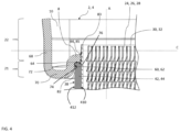
- the first portion 21 is formed successively of an external wall 68, which extends in the longitudinal extension of the second portion 22, of a bottom wall 70, which forms the bottom of the cavity previously mentioned by extending substantially perpendicularly the external wall 68 in the direction of the interior of the collector plate 2, 4, namely towards the perforated wall 8, and finally of a fold wall 72, which extends perpendicularly the bottom wall 70, opposite the external wall 68 and up to the perforated wall 8.
- the perforated wall 8 is stamped locally, around each of the through openings 12, so as to have an end edge rolled towards the inside of the corresponding collector plate, that is to say in the direction of the second portion 22.
- the perforated wall comprises on the periphery of each through opening a border 83 which forms a projection of the perforated wall and which ensures an elongation of the contact surface with the tubes inside the corresponding collector plate.
- the housing 82 sized to receive the corresponding longitudinal end 60, 62, is formed between the end faces 34 of the tubes 24, the internal face 74 of the folding wall 72 and the internal face 76 of the perforated wall 8, said internal faces being turned towards the heat exchange bundle.
- the transverse wall 42, 44 intended to be positioned in the housing 82 is configured according to the invention to be in contact with the corresponding collector plate 2, 4, in a plane surface contact made in a plane perpendicular to the longitudinal direction A.
- the transverse wall has a straight edge at each longitudinal end 60, 62, that is to say an edge perpendicular to the main elongation plane, here longitudinal and transverse, of the transverse wall.
- an inclined plane forming a ramp may be locally provided on this straight edge, but it should be noted that the major part of the longitudinal end has the shape of this straight edge, that is to say extending in a plane perpendicular to the main elongation plane of the transverse wall.
- the longitudinal end 60, 62 of one of the transverse walls 42, 44 of the casing 38 is in contact at least with the internal face 76 of the perforated wall 8, this contact being made at least in a plane parallel to the transverse B and vertical C directions.
- the longitudinal end 60, 62 and the perforated wall 8 thus define a contact zone 64, the latter extending continuously along the transverse direction B between the first tube 26 and the last tube 28.
- This contact zone 64 contributes to sealing the internal volume of the heat exchange bundle 6, at least at the level of the transverse walls 42, 44 of the casing 38 and the collector plates 2, 4 specific to the admission and distribution of fluid.
- the sealing is ensured in particular by a brazing operation carried out in a suitable furnace, which tends to ensure contact between the straight edge of the longitudinal ends of the transverse walls and the internal face 76 of the perforated wall 8.
- the brazing operation also makes it possible to make the transverse walls 42, 44 of the casing 38 integral with the end faces 34 of at least the first and last tubes 26, 28 of the plurality of tubes 24, the contact extending substantially along the longitudinal direction A between each of the longitudinal ends 60, 62 of the transverse walls 42, 44, so as again to ensure the sealing of the internal volume of the heat exchange bundle 6.
- the end faces 34 of other tubes 24 of the plurality of tubes 24 may also be in contact with the transverse walls 42, 44 of the casing 38, these contacts participating in delimiting partially closed spaces of the internal volume of the heat exchange bundle 6.
- the brazing operation can also make it possible to make the longitudinal end 60, 62 of the transverse wall 42, 44 integral with the fold wall 72 of the collector plate 2, 4, the contact being made at least in a plane parallel to the longitudinal A and transverse B directions.
- the shapes and dimensions of the housing 82 on the one hand and of the longitudinal end 60, 62 of the transverse wall 42, 44 on the other hand make it possible to insert the transverse wall into the housing until the surface contact between the longitudinal end and the perforated wall is effective and forms a stop to the movement. This ensures that the transverse wall is correctly inserted before the brazing operation, that is to say that the transverse wall is sufficiently close to the perforated wall for the brazing operation to be effective and to ensure the sealing of the heat exchange surface.
- the envelope 38 comprises at least one protrusion 84 which locally extends the envelope 38 along the longitudinal direction A. More precisely, each protrusion 84 locally extends a longitudinal end 60, 62 of a transverse wall 40, 42 of the envelope 38, it being understood that this longitudinal end retains a predominantly planar shape perpendicular to the main elongation plane of the transverse wall.
- the at least one protrusion 84 is made projecting from the longitudinal end 60, 62 and is configured to fill the clearance 85 present between the perforated wall 8 and the corresponding tube 24.
- the edge of the perforated wall 8 participating in delimiting a through opening 12 is folded so that a stamping radius participates in delimiting a clearance 85 forming, between the tube and the longitudinal end of the casing, a leakage space.
- the protrusion 84 of the longitudinal end 60, 62 is housed in this escape space by presenting a structural complementarity with each of the components delimiting this space.
- An inner surface 410 of the transverse wall is defined as the surface opposite the tubes on which the flat portion of the transverse wall rests, and an outer surface 412 of the transverse wall as the opposite surface.
- the longitudinal end 60, 62 of the transverse wall has a predominantly straight edge and the protrusion 84, which partly extends the longitudinal end 60, 62 of the casing 38 along the longitudinal direction A, extends locally in the extension of the internal surface 410, that is to say as close as possible to the internal volume of the heat exchange bundle 6 so as to be able to be in contact with the tube 24.
- the thickness, or dimension in the vertical direction C, of the protrusion 84 is less than the thickness, or corresponding dimension in the same vertical direction, of the transverse wall.
- the protrusion 84 may in particular have a thickness whose value is substantially equal to 10 to 20% of the value of the thickness of the transverse wall.
- Each protrusion 84 provided as an extension of the transverse wall of the envelope extends along the transverse direction B over a distance substantially equal to the transverse dimension of the tube 24 in contact with which this protrusion is intended to be.
- the protrusion 84 is arranged on the casing so as to be in contact with the first tube 26 or the last tube 28 of the plurality of tubes 24, at least two protrusions 84 being provided, opposite one another in the transverse direction B, on the same longitudinal end to cooperate respectively with the first tube 26 and the last tube 28.
- the first tube 26, the last tube 28, the protrusions 84, the collector plates 2, 4 and the transverse walls 42, 44 of the casing 38 delimit a sealed space for the circulation of a fluid, in particular after a brazing operation made possible by the proximity of material of each of the components cited above before passing into the brazing furnace.
- each of the aforementioned elements participates in guiding the circulation of a fluid between the tubes 24 from the first transverse wall 42 of the casing 38 towards the second transverse wall 44 of the casing 38.
- the casing 38 may comprise a protrusion 84 at each contact zone 64 close to a tube 24, in addition to those intended to be in contact with the first and last tubes 26, 28.
- the protrusions 84 delimit different sealed circulation spaces in the internal volume of the heat exchange bundle 6, the number of sealed circulation spaces thus being correlated to the number of protrusions 84 of the casing 38.
- the protrusion 84 is made in one piece with the corresponding transverse wall 40, 42, so as to advantageously form a single-piece assembly with the casing 38. This characteristic facilitates the manufacture and assembly of the heat exchanger 1, but it should be noted that a protrusion 84 forming an entity made separately from the casing 38 and attached to the latter would not depart from the scope of the invention.
- the protrusion 84 is made of a material similar to the casing 38 and the collector plates 2, 4. Indeed, as mentioned previously, during the assembly of the heat exchanger 1, the perforated wall 8 at the contact zone 64 and the longitudinal end 60, 62 are made at least partially integral with each other by brazing and it is appropriate that the filler material necessary for the brazing operation is chemically integral with the protrusion 84, the longitudinal end 60, 62 and the collector plate.
- the heat exchanger 1 has the function of cooling gases circulating through itself.
- the intake manifold receives the gases from the engine fuel circuit and then guides them, via the first collector plate 2, to the heat exchange core 6 through the plurality of tubes 24 where they are cooled, increasing their oxygen concentration. The cooled gases are then guided to the distribution manifold 4 and to the engine.
- the gases are cooled in the plurality of tubes 24 by heat exchange with another fluid, through the wall of each tube 24 of the plurality of tubes 24.
- the second fluid circulates between the plurality of tubes 24 in the internal volume of the heat exchange bundle 6 from the circular orifice 50 of the first transverse wall 42 to the circular orifice 50 of the second transverse wall 44.
- the second fluid may for example be a heat transfer fluid, cooling the gases circulating in the plurality of tubes 24.
- the contact zone 64 between the longitudinal end 60, 62, the protrusion 84 and the perforated wall 8 and its clearance 85, as well as the contact between the transverse walls 42, 44 and the first and last tubes 26, 28 contribute to making the heat exchange bundle 6 leaktight so as to limit the possibility of leakage of the other fluid circulating in the internal volume of the heat exchange bundle 6.
- the internal volume of the heat exchange bundle can be traversed by at least two fluids, the transverse walls then comprising two fluid inlets, two distribution bearings, two receiving bearings and two fluid outlets, a protrusion being positioned at each contact zone close to the tube of the plurality of tubes delimiting the two fluid circulation spaces.
Landscapes
- Engineering & Computer Science (AREA)
- Physics & Mathematics (AREA)
- Thermal Sciences (AREA)
- Mechanical Engineering (AREA)
- General Engineering & Computer Science (AREA)
- Chemical & Material Sciences (AREA)
- Combustion & Propulsion (AREA)
- Heat-Exchange Devices With Radiators And Conduit Assemblies (AREA)
- Cooling, Air Intake And Gas Exhaust, And Fuel Tank Arrangements In Propulsion Units (AREA)
Claims (7)
- Wärmeaustauscher (1), beinhaltend eine erste Sammelplatte (2) eines Einlassendbodens, eine zweite Sammelplatte (4) eines Verteilerendbodens und ein Wärmeaustauschbündel (6), das sich zwischen der ersten Sammelplatte (2) und der zweiten Sammelplatte (4) entlang einer Längsrichtung (A) erstreckt, wobei das Wärmeaustauschbündel (6) durch ein Gehäuse (38) begrenzt wird und eine Vielzahl von Rohren (24) beinhaltet, die aufeinanderfolgend nebeneinander entlang einer Querrichtung (B) angeordnet sind, wobei jedes Rohr (24) dazu fähig ist, über Durchgangsöffnungen (12), die in jeder Platte eingerichtet sind, mit den Sammelplatten (2, 4) zusammenzuwirken, dadurch gekennzeichnet, dass das Gehäuse (38) mindestens ein Längsende (60, 62) mit gerader Kante aufweist, das dazu konfiguriert ist, in einem Kontaktbereich (64) mit mindestens einer Sammelplatte (2, 4) in ebenem Flächenkontakt zu stehen, wobei der Flächenkontakt hauptsächlich in einer zu der Längsrichtung (A) senkrechten Ebene hergestellt ist,wobei die Sammelplatte (2, 4) eine durchbrochene Wand (8), in der die Durchgangsöffnungen (12) hergestellt sind, und einen Rahmen (10), der am Umfang der durchbrochenen Wand eingerichtet ist und dazu konfiguriert ist, mit dem Gehäuse (38) zusammenzuwirken, umfasst,und wobei das mindestens eine Längsende (60, 62) mit gerader Kante des Gehäuses (38) mindestens einen Vorsprung (84) beinhaltet, der das Gehäuse (38) entlang der Längsrichtung (A) verlängert,wobei die Vielzahl von Rohren des Wärmeaustauschbündels (6) mindestens ein erstes Rohr (26) und ein letztes Rohr (28) beinhaltet, die jeweils an jedem Querende der Vielzahl von Rohren angeordnet sind, dadurch gekennzeichnet, dass das Gehäuse (38) mindestens einen ersten Vorsprung (84) in Kontakt mit dem ersten Rohr (26) und einen zweiten Vorsprung (84) in Kontakt mit dem letzten Rohr (28) beinhaltet und dass die durchbrochene Wand (8) im Bereich jeder Durchgangsöffnung eine Aussparung (85) aufweist, die durch eine gerundete Kante oder eine Abschrägung gebildet wird, wobei jeder Vorsprung (84) eine Form und Abmessungen aufweist, die zu denjenigen der Aussparung (85) komplementär sind.
- Wärmeaustauscher (1) nach Anspruch 1, wobei das Gehäuse (38) auch in einer zu der Längsrichtung (A) parallelen Ebene mit der mindestens einen Sammelplatte in ebenem Flächenkontakt steht.
- Wärmeaustauscher (1) nach einem der vorhergehenden Ansprüche, wobei die Rohre aufeinanderfolgend nebeneinander entlang der Querrichtung (B) angeordnet sind und wobei das Gehäuse mindestens eine Querwand (42, 44) umfasst, die sich entlang dieser Querrichtung erstreckt und dabei mit jedem der Rohre (24) in Kontakt steht, wobei der Flächenkontakt zwischen Sammelplatte und Rohr an dem Längsende dieser Querwand gebildet ist.
- Wärmeaustauscher (1) nach Anspruch 2 oder 3, wobei jeder Vorsprung (84) eine Querabmessung aufweist, die im Wesentlichen gleich der Querabmessung des in dem entsprechenden Kontaktbereich angeordneten Rohrs ist.
- Wärmeaustauscher (1) nach Anspruch 2, 3 oder 4, wobei jeder Vorsprung (84) eine vertikale Abmessung C aufweist, die kleiner als die vertikale Abmessung der Querwand (42, 44) ist.
- Wärmeaustauscher (1) nach einem der Ansprüche 1 bis 5, wobei die durchbrochene Wand (8) lokal um jede der Durchgangsöffnungen (12) herum tiefgezogen ist, um eine profilierte Endkante, die eine von der durchbrochenen Wand vorstehende Umrandung (83) bildet, aufzuweisen und die Kontaktfläche zu den Rohren (24) zu vergrößern.
- Wärmeaustauscher (1) nach einem der vorhergehenden Ansprüche, wobei das Gehäuse (38) in einem ersten Kontaktbereich (64) ein erstes Längsende (60) mit gerader Kante in Kontakt mit der ersten Sammelplatte (2) und in einem zweiten Kontaktbereich (64) ein zweites Längsende (62) mit gerader Kante in Kontakt mit der zweiten Sammelplatte (4) aufweist.
Applications Claiming Priority (2)
| Application Number | Priority Date | Filing Date | Title |
|---|---|---|---|
| FR2002730A FR3108395B1 (fr) | 2020-03-20 | 2020-03-20 | Echangeur thermique pour véhicule automobile |
| PCT/EP2021/056998 WO2021185987A1 (fr) | 2020-03-20 | 2021-03-18 | Echangeur thermique pour véhicule automobile |
Publications (2)
| Publication Number | Publication Date |
|---|---|
| EP4121708A1 EP4121708A1 (de) | 2023-01-25 |
| EP4121708B1 true EP4121708B1 (de) | 2025-06-04 |
Family
ID=70228365
Family Applications (1)
| Application Number | Title | Priority Date | Filing Date |
|---|---|---|---|
| EP21711925.4A Active EP4121708B1 (de) | 2020-03-20 | 2021-03-18 | Wärmetauscher für ein kraftfahrzeug |
Country Status (5)
| Country | Link |
|---|---|
| US (1) | US12385696B2 (de) |
| EP (1) | EP4121708B1 (de) |
| CN (1) | CN115298503B (de) |
| FR (1) | FR3108395B1 (de) |
| WO (1) | WO2021185987A1 (de) |
Families Citing this family (1)
| Publication number | Priority date | Publication date | Assignee | Title |
|---|---|---|---|---|
| EP3945264B1 (de) * | 2020-07-26 | 2025-05-14 | Valeo Autosystemy SP. Z.O.O. | Elektrischer flüssigkeitserhitzer |
Citations (1)
| Publication number | Priority date | Publication date | Assignee | Title |
|---|---|---|---|---|
| EP1995544B1 (de) * | 2007-05-24 | 2018-07-18 | MAHLE Behr GmbH & Co. KG | Wärmetauscher, insbesondere Ladeluftkühler oder Abgaskühler für eine Brennkraftmaschine eines Kraftfahrzeuges und dessen Herstellungsverfahren |
Family Cites Families (9)
| Publication number | Priority date | Publication date | Assignee | Title |
|---|---|---|---|---|
| DE10233407B4 (de) * | 2001-07-26 | 2016-02-18 | Denso Corporation | Abgaswärmeaustauscher |
| FR2933177B1 (fr) * | 2008-06-26 | 2018-05-25 | Valeo Systemes Thermiques Branche Thermique Moteur | Echangeur de chaleur et carter pour l'echangeur |
| FR2968750B1 (fr) * | 2010-12-10 | 2015-12-11 | Valeo Systemes Thermiques | Echangeur de chaleur, notamment pour vehicule automobile |
| FR2991036B1 (fr) * | 2012-05-22 | 2022-03-11 | Valeo Systemes Thermiques | Plaque collectrice pour une boite collectrice d'un echangeur de chaleur de vehicule automobile |
| FR2991037B1 (fr) * | 2012-05-24 | 2014-06-20 | Valeo Systemes Thermiques | Echangeur de chaleur a collecteur renforce |
| FR3030709B1 (fr) * | 2014-12-18 | 2019-04-05 | Valeo Systemes Thermiques | Echangeur de chaleur |
| KR101896326B1 (ko) * | 2016-09-09 | 2018-09-07 | 현대자동차 주식회사 | 수냉식 이지알 쿨러 |
| DE102016011254A1 (de) * | 2016-09-20 | 2018-03-22 | Modine Manufacturing Company | Bypass-Blockiervorrichtung für Wärmeübertrager |
| GB2588636B8 (en) * | 2019-10-30 | 2023-08-30 | Denso Marston Ltd | A heat exchanger |
-
2020
- 2020-03-20 FR FR2002730A patent/FR3108395B1/fr active Active
-
2021
- 2021-03-18 EP EP21711925.4A patent/EP4121708B1/de active Active
- 2021-03-18 CN CN202180023266.6A patent/CN115298503B/zh active Active
- 2021-03-18 WO PCT/EP2021/056998 patent/WO2021185987A1/fr not_active Ceased
- 2021-03-18 US US17/912,304 patent/US12385696B2/en active Active
Patent Citations (1)
| Publication number | Priority date | Publication date | Assignee | Title |
|---|---|---|---|---|
| EP1995544B1 (de) * | 2007-05-24 | 2018-07-18 | MAHLE Behr GmbH & Co. KG | Wärmetauscher, insbesondere Ladeluftkühler oder Abgaskühler für eine Brennkraftmaschine eines Kraftfahrzeuges und dessen Herstellungsverfahren |
Also Published As
| Publication number | Publication date |
|---|---|
| CN115298503B (zh) | 2025-08-12 |
| US20230194181A1 (en) | 2023-06-22 |
| WO2021185987A1 (fr) | 2021-09-23 |
| FR3108395A1 (fr) | 2021-09-24 |
| US12385696B2 (en) | 2025-08-12 |
| FR3108395B1 (fr) | 2022-11-11 |
| EP4121708A1 (de) | 2023-01-25 |
| CN115298503A (zh) | 2022-11-04 |
Similar Documents
| Publication | Publication Date | Title |
|---|---|---|
| EP2513585B1 (de) | Wärmetauscher | |
| EP2972049B1 (de) | Wärmetauscher, insbesondere supraladender luftkühler | |
| EP2064506B1 (de) | Wärmetauscher, insbesondere ein systemluftkühler | |
| EP2912396B1 (de) | Wärmetauscher, insbesondere für ein kraftfahrzeug | |
| EP2652425A2 (de) | Gestapelter plattenwärmetauscher | |
| FR2855604A1 (fr) | Echangeur de chaleur a plaques comportant un element d'obturation des fuites du gaz a fefroidir. | |
| EP2169195B1 (de) | Wärmeaustauschelement von einem wärmeaustauscheinheit in einem Wärmetauscher | |
| EP4121708B1 (de) | Wärmetauscher für ein kraftfahrzeug | |
| EP3384224B1 (de) | Kraftfahrzeugwärmetauscher mit einem ausgleichsbehälter | |
| EP2856059A1 (de) | Wärmetauscher mit verstärktem kollektor | |
| EP1636533B1 (de) | Wärmetauscher mit einem gehäuse und einem bündel, die aus aluminiumblech hergestellt und hartverlötet sind | |
| WO2024028091A1 (fr) | Dispositif de regulation thermique, notamment de refroidissement pour vehicule automobile | |
| FR2935912A1 (fr) | Procede d'assemblage et de brasage de deux pieces munies d'elements d'assemblage. | |
| EP2171247A1 (de) | Mittels einer wärmebrücke mit einem wärmetauscher verbundenes regulatorventil und entsprechende wärmetauschervorrichtung | |
| EP3449198B1 (de) | Sammler und zugehörige kühlvorrichtung | |
| FR3030709A1 (fr) | Echangeur de chaleur | |
| WO2020128194A1 (fr) | Cadre configure pour le support d'un echangeur de chaleur | |
| EP3663695B1 (de) | Konstitutiver sammelbehälter für einen wärmetauscher | |
| FR3077127A1 (fr) | Echangeur thermique, notamment pour la regulation thermique de batteries | |
| FR2997486A1 (fr) | Tube d'echangeur de chaleur a moyen de perturbation plat | |
| FR3139295A1 (fr) | Module thermique pour véhicule automobile. | |
| WO2024251686A1 (fr) | Elément interne d'échangeur de chaleur | |
| WO2019229356A1 (fr) | Boîte collectrice pour un échangeur de chaleur | |
| FR3088710A1 (fr) | Echangeur de chaleur pour vehicule automobile | |
| EP1623177A2 (de) | Wärmetauscher, insbesondere für kraftfahrzeuge |
Legal Events
| Date | Code | Title | Description |
|---|---|---|---|
| STAA | Information on the status of an ep patent application or granted ep patent |
Free format text: STATUS: UNKNOWN |
|
| STAA | Information on the status of an ep patent application or granted ep patent |
Free format text: STATUS: THE INTERNATIONAL PUBLICATION HAS BEEN MADE |
|
| PUAI | Public reference made under article 153(3) epc to a published international application that has entered the european phase |
Free format text: ORIGINAL CODE: 0009012 |
|
| STAA | Information on the status of an ep patent application or granted ep patent |
Free format text: STATUS: REQUEST FOR EXAMINATION WAS MADE |
|
| 17P | Request for examination filed |
Effective date: 20221005 |
|
| AK | Designated contracting states |
Kind code of ref document: A1 Designated state(s): AL AT BE BG CH CY CZ DE DK EE ES FI FR GB GR HR HU IE IS IT LI LT LU LV MC MK MT NL NO PL PT RO RS SE SI SK SM TR |
|
| DAV | Request for validation of the european patent (deleted) | ||
| DAX | Request for extension of the european patent (deleted) | ||
| GRAP | Despatch of communication of intention to grant a patent |
Free format text: ORIGINAL CODE: EPIDOSNIGR1 |
|
| STAA | Information on the status of an ep patent application or granted ep patent |
Free format text: STATUS: GRANT OF PATENT IS INTENDED |
|
| INTG | Intention to grant announced |
Effective date: 20250107 |
|
| GRAS | Grant fee paid |
Free format text: ORIGINAL CODE: EPIDOSNIGR3 |
|
| GRAA | (expected) grant |
Free format text: ORIGINAL CODE: 0009210 |
|
| STAA | Information on the status of an ep patent application or granted ep patent |
Free format text: STATUS: THE PATENT HAS BEEN GRANTED |
|
| AK | Designated contracting states |
Kind code of ref document: B1 Designated state(s): AL AT BE BG CH CY CZ DE DK EE ES FI FR GB GR HR HU IE IS IT LI LT LU LV MC MK MT NL NO PL PT RO RS SE SI SK SM TR |
|
| REG | Reference to a national code |
Ref country code: GB Ref legal event code: FG4D Free format text: NOT ENGLISH |
|
| REG | Reference to a national code |
Ref country code: CH Ref legal event code: EP |
|
| REG | Reference to a national code |
Ref country code: DE Ref legal event code: R096 Ref document number: 602021031737 Country of ref document: DE |
|
| REG | Reference to a national code |
Ref country code: IE Ref legal event code: FG4D Free format text: LANGUAGE OF EP DOCUMENT: FRENCH |
|
| REG | Reference to a national code |
Ref country code: NL Ref legal event code: MP Effective date: 20250604 |
|
| PG25 | Lapsed in a contracting state [announced via postgrant information from national office to epo] |
Ref country code: FI Free format text: LAPSE BECAUSE OF FAILURE TO SUBMIT A TRANSLATION OF THE DESCRIPTION OR TO PAY THE FEE WITHIN THE PRESCRIBED TIME-LIMIT Effective date: 20250604 Ref country code: ES Free format text: LAPSE BECAUSE OF FAILURE TO SUBMIT A TRANSLATION OF THE DESCRIPTION OR TO PAY THE FEE WITHIN THE PRESCRIBED TIME-LIMIT Effective date: 20250604 |
|
| REG | Reference to a national code |
Ref country code: LT Ref legal event code: MG9D |
|
| PG25 | Lapsed in a contracting state [announced via postgrant information from national office to epo] |
Ref country code: NO Free format text: LAPSE BECAUSE OF FAILURE TO SUBMIT A TRANSLATION OF THE DESCRIPTION OR TO PAY THE FEE WITHIN THE PRESCRIBED TIME-LIMIT Effective date: 20250904 Ref country code: GR Free format text: LAPSE BECAUSE OF FAILURE TO SUBMIT A TRANSLATION OF THE DESCRIPTION OR TO PAY THE FEE WITHIN THE PRESCRIBED TIME-LIMIT Effective date: 20250905 |
|
| PG25 | Lapsed in a contracting state [announced via postgrant information from national office to epo] |
Ref country code: PL Free format text: LAPSE BECAUSE OF FAILURE TO SUBMIT A TRANSLATION OF THE DESCRIPTION OR TO PAY THE FEE WITHIN THE PRESCRIBED TIME-LIMIT Effective date: 20250604 |
|
| PG25 | Lapsed in a contracting state [announced via postgrant information from national office to epo] |
Ref country code: BG Free format text: LAPSE BECAUSE OF FAILURE TO SUBMIT A TRANSLATION OF THE DESCRIPTION OR TO PAY THE FEE WITHIN THE PRESCRIBED TIME-LIMIT Effective date: 20250604 |
|
| PG25 | Lapsed in a contracting state [announced via postgrant information from national office to epo] |
Ref country code: HR Free format text: LAPSE BECAUSE OF FAILURE TO SUBMIT A TRANSLATION OF THE DESCRIPTION OR TO PAY THE FEE WITHIN THE PRESCRIBED TIME-LIMIT Effective date: 20250604 |
|
| PG25 | Lapsed in a contracting state [announced via postgrant information from national office to epo] |
Ref country code: RS Free format text: LAPSE BECAUSE OF FAILURE TO SUBMIT A TRANSLATION OF THE DESCRIPTION OR TO PAY THE FEE WITHIN THE PRESCRIBED TIME-LIMIT Effective date: 20250904 |
|
| PG25 | Lapsed in a contracting state [announced via postgrant information from national office to epo] |
Ref country code: LV Free format text: LAPSE BECAUSE OF FAILURE TO SUBMIT A TRANSLATION OF THE DESCRIPTION OR TO PAY THE FEE WITHIN THE PRESCRIBED TIME-LIMIT Effective date: 20250604 |
|
| PG25 | Lapsed in a contracting state [announced via postgrant information from national office to epo] |
Ref country code: NL Free format text: LAPSE BECAUSE OF FAILURE TO SUBMIT A TRANSLATION OF THE DESCRIPTION OR TO PAY THE FEE WITHIN THE PRESCRIBED TIME-LIMIT Effective date: 20250604 |
|
| PG25 | Lapsed in a contracting state [announced via postgrant information from national office to epo] |
Ref country code: PT Free format text: LAPSE BECAUSE OF FAILURE TO SUBMIT A TRANSLATION OF THE DESCRIPTION OR TO PAY THE FEE WITHIN THE PRESCRIBED TIME-LIMIT Effective date: 20251006 |
|
| REG | Reference to a national code |
Ref country code: AT Ref legal event code: MK05 Ref document number: 1800692 Country of ref document: AT Kind code of ref document: T Effective date: 20250604 |
|
| PG25 | Lapsed in a contracting state [announced via postgrant information from national office to epo] |
Ref country code: IS Free format text: LAPSE BECAUSE OF FAILURE TO SUBMIT A TRANSLATION OF THE DESCRIPTION OR TO PAY THE FEE WITHIN THE PRESCRIBED TIME-LIMIT Effective date: 20251004 |
|
| PG25 | Lapsed in a contracting state [announced via postgrant information from national office to epo] |
Ref country code: SM Free format text: LAPSE BECAUSE OF FAILURE TO SUBMIT A TRANSLATION OF THE DESCRIPTION OR TO PAY THE FEE WITHIN THE PRESCRIBED TIME-LIMIT Effective date: 20250604 Ref country code: AT Free format text: LAPSE BECAUSE OF FAILURE TO SUBMIT A TRANSLATION OF THE DESCRIPTION OR TO PAY THE FEE WITHIN THE PRESCRIBED TIME-LIMIT Effective date: 20250604 |