EP4121618B1 - Gebäudeserviceelement - Google Patents
Gebäudeserviceelement Download PDFInfo
- Publication number
- EP4121618B1 EP4121618B1 EP22716878.8A EP22716878A EP4121618B1 EP 4121618 B1 EP4121618 B1 EP 4121618B1 EP 22716878 A EP22716878 A EP 22716878A EP 4121618 B1 EP4121618 B1 EP 4121618B1
- Authority
- EP
- European Patent Office
- Prior art keywords
- building
- casing
- building service
- service element
- elements
- Prior art date
- Legal status (The legal status is an assumption and is not a legal conclusion. Google has not performed a legal analysis and makes no representation as to the accuracy of the status listed.)
- Active
Links
Images


Classifications
-
- E—FIXED CONSTRUCTIONS
- E04—BUILDING
- E04F—FINISHING WORK ON BUILDINGS, e.g. STAIRS, FLOORS
- E04F17/00—Vertical ducts; Channels, e.g. for drainage
- E04F17/08—Vertical ducts; Channels, e.g. for drainage for receiving utility lines, e.g. cables, pipes
-
- F—MECHANICAL ENGINEERING; LIGHTING; HEATING; WEAPONS; BLASTING
- F24—HEATING; RANGES; VENTILATING
- F24D—DOMESTIC- OR SPACE-HEATING SYSTEMS, e.g. CENTRAL HEATING SYSTEMS; DOMESTIC HOT-WATER SUPPLY SYSTEMS; ELEMENTS OR COMPONENTS THEREFOR
- F24D5/00—Hot-air central heating systems; Exhaust gas central heating systems
- F24D5/12—Hot-air central heating systems; Exhaust gas central heating systems using heat pumps
-
- F—MECHANICAL ENGINEERING; LIGHTING; HEATING; WEAPONS; BLASTING
- F24—HEATING; RANGES; VENTILATING
- F24F—AIR-CONDITIONING; AIR-HUMIDIFICATION; VENTILATION; USE OF AIR CURRENTS FOR SCREENING
- F24F11/00—Control or safety arrangements
- F24F11/70—Control systems characterised by their outputs; Constructional details thereof
- F24F11/72—Control systems characterised by their outputs; Constructional details thereof for controlling the supply of treated air, e.g. its pressure
-
- F—MECHANICAL ENGINEERING; LIGHTING; HEATING; WEAPONS; BLASTING
- F24—HEATING; RANGES; VENTILATING
- F24F—AIR-CONDITIONING; AIR-HUMIDIFICATION; VENTILATION; USE OF AIR CURRENTS FOR SCREENING
- F24F12/00—Use of energy recovery systems in air conditioning, ventilation or screening
- F24F12/001—Use of energy recovery systems in air conditioning, ventilation or screening with heat-exchange between supplied and exhausted air
- F24F12/006—Use of energy recovery systems in air conditioning, ventilation or screening with heat-exchange between supplied and exhausted air using an air-to-air heat exchanger
-
- F—MECHANICAL ENGINEERING; LIGHTING; HEATING; WEAPONS; BLASTING
- F24—HEATING; RANGES; VENTILATING
- F24F—AIR-CONDITIONING; AIR-HUMIDIFICATION; VENTILATION; USE OF AIR CURRENTS FOR SCREENING
- F24F5/00—Air-conditioning systems or apparatus not covered by F24F1/00 or F24F3/00, e.g. using solar heat or combined with household units such as an oven or water heater
- F24F5/0096—Air-conditioning systems or apparatus not covered by F24F1/00 or F24F3/00, e.g. using solar heat or combined with household units such as an oven or water heater combined with domestic apparatus
-
- F—MECHANICAL ENGINEERING; LIGHTING; HEATING; WEAPONS; BLASTING
- F24—HEATING; RANGES; VENTILATING
- F24H—FLUID HEATERS, e.g. WATER OR AIR HEATERS, HAVING HEAT-GENERATING MEANS, e.g. HEAT PUMPS, IN GENERAL
- F24H1/00—Water heaters, e.g. boilers, continuous-flow heaters or water-storage heaters
- F24H1/18—Water-storage heaters
- F24H1/20—Water-storage heaters with immersed heating elements, e.g. electric elements or furnace tubes
- F24H1/201—Water-storage heaters with immersed heating elements, e.g. electric elements or furnace tubes using electric energy supply
-
- F—MECHANICAL ENGINEERING; LIGHTING; HEATING; WEAPONS; BLASTING
- F24—HEATING; RANGES; VENTILATING
- F24H—FLUID HEATERS, e.g. WATER OR AIR HEATERS, HAVING HEAT-GENERATING MEANS, e.g. HEAT PUMPS, IN GENERAL
- F24H3/00—Air heaters
- F24H3/02—Air heaters with forced circulation
- F24H3/022—Air heaters with forced circulation using electric energy supply
-
- F—MECHANICAL ENGINEERING; LIGHTING; HEATING; WEAPONS; BLASTING
- F24—HEATING; RANGES; VENTILATING
- F24H—FLUID HEATERS, e.g. WATER OR AIR HEATERS, HAVING HEAT-GENERATING MEANS, e.g. HEAT PUMPS, IN GENERAL
- F24H4/00—Fluid heaters characterised by the use of heat pumps
- F24H4/02—Water heaters
- F24H4/04—Storage heaters
-
- F—MECHANICAL ENGINEERING; LIGHTING; HEATING; WEAPONS; BLASTING
- F24—HEATING; RANGES; VENTILATING
- F24H—FLUID HEATERS, e.g. WATER OR AIR HEATERS, HAVING HEAT-GENERATING MEANS, e.g. HEAT PUMPS, IN GENERAL
- F24H4/00—Fluid heaters characterised by the use of heat pumps
- F24H4/06—Air heaters
-
- F—MECHANICAL ENGINEERING; LIGHTING; HEATING; WEAPONS; BLASTING
- F24—HEATING; RANGES; VENTILATING
- F24F—AIR-CONDITIONING; AIR-HUMIDIFICATION; VENTILATION; USE OF AIR CURRENTS FOR SCREENING
- F24F2110/00—Control inputs relating to air properties
- F24F2110/20—Humidity
-
- F—MECHANICAL ENGINEERING; LIGHTING; HEATING; WEAPONS; BLASTING
- F24—HEATING; RANGES; VENTILATING
- F24F—AIR-CONDITIONING; AIR-HUMIDIFICATION; VENTILATION; USE OF AIR CURRENTS FOR SCREENING
- F24F2110/00—Control inputs relating to air properties
- F24F2110/50—Air quality properties
- F24F2110/65—Concentration of specific substances or contaminants
- F24F2110/70—Carbon dioxide
-
- F—MECHANICAL ENGINEERING; LIGHTING; HEATING; WEAPONS; BLASTING
- F24—HEATING; RANGES; VENTILATING
- F24F—AIR-CONDITIONING; AIR-HUMIDIFICATION; VENTILATION; USE OF AIR CURRENTS FOR SCREENING
- F24F2221/00—Details or features not otherwise provided for
- F24F2221/18—Details or features not otherwise provided for combined with domestic apparatus
- F24F2221/183—Details or features not otherwise provided for combined with domestic apparatus combined with a hot-water boiler
-
- F—MECHANICAL ENGINEERING; LIGHTING; HEATING; WEAPONS; BLASTING
- F24—HEATING; RANGES; VENTILATING
- F24F—AIR-CONDITIONING; AIR-HUMIDIFICATION; VENTILATION; USE OF AIR CURRENTS FOR SCREENING
- F24F2221/00—Details or features not otherwise provided for
- F24F2221/54—Heating and cooling, simultaneously or alternatively
Definitions
- the invention relates to a system including a building service element for fastening in front of an outer wall of a building and in particular of an existing building. It can be used in particular in the context of an energy-efficient building renovation, but is also suitable for use in new buildings.
- the refurbishment should ultimately enable buildings to be operated in a CO 2 -neutral manner.
- Numerous approaches to energy-efficient building refurbishment have already been developed and tested in the past, but for various reasons they have been problematic or at least have not gained acceptance on a significant scale.
- a "serial renovation" to climate-neutral buildings based on the principles of the Passive House Standard is currently being discussed in Germany as a promising concept.
- the German patent application DE 10 2021 107 398.7 discloses a process for energy-efficient building refurbishment that includes, as an essential process element, covering the outer walls of existing buildings with prefabricated flat facade elements and building service elements.
- the building service elements should contain as much of the necessary building services as possible so that major construction work inside the building can be dispensed with during refurbishment.
- the building service elements, together with the facade elements are to form a flush and attractive outer surface of the buildings.
- the object of the invention is to provide a system including a building service element that meets these requirements and can supply residential units with the respective required building technology on the basis of different supply variants.
- the invention relates to a system according to claim 1.
- the system comprises building service element for fastening in front of an outer wall of a building and, in particular, of an existing building, and at least one soffit element for insertion into a door- or window-opening in the outer wall of the building.
- the building service element has a casing which comprises at least one receiving region with preassembled domestic engineering components and a shaft region running through the casing from top to bottom, wherein the receiving region and the shaft region are arranged next to one another, and wherein the building service element has, on the front side, a large-area or full-area access opening through which both the receiving region and the shaft region are accessible and which is reversibly closed.
- the the soffit element has side panels corresponding to a respective edge of the door- or window-opening, wherein the side panels are backed with a heater acting thereon in a largesurface manner, wherein the heater is connected to a domestic engineering component of the building service element for the purpose of energy supply, the heating preferably being a heating mat whose heating elements are formed as electrical resistance heatings.
- the building service element has at least one closure element in the form of, for example, a door that can be pivoted about a vertical axis or a flap that can be pivoted about a horizontal axis.
- the access opening can be closed by means of one or two such doors or flaps, wherein, if necessary, a part of the access opening located in front of the receiving region can be closed by such a door or flap and a part of the access opening located in front of the shaft region can be closed by a further such door or flap.
- the closure element is thermally insulated.
- the entire building service element is thermally insulated at least to the front, to the sides and to the top and bottom.
- the thermal insulation can be realized by a renewable and biodegradable insulation material, such as cellulose material or wood fiber material.
- vacuum insulation is particularly preferred, since such insulations have especially good insulating properties, which, despite relatively thin doors, make it possible to achieve a high insulating effect that is comparable with the facade elements arranged next to them in a possible application of the building service elements.
- the abutment surfaces between the closure element and the casing are preferably provided with a circumferential seal on at least one side in order to achieve a minimum air leakage rate and the highest possible casing tightness with respect to air exchange, moisture ingress, etc.
- the casing of the building service element preferably has a flat rectangular shape.
- the casing is further preferably higher than wide.
- Flat preferably means that the length of the shorter side of the casing, mostly the width, is at least three times the depth thereof, and/or that the length of the longer side of the casing, mostly the height, is at least five times the depth thereof.
- the casing is manufactured in a frame construction.
- it may comprise an outer frame and one or more struts, wherein a strut may extend between the receiving region and the shaft region.
- the closure elements for the removal opening may also be manufactured in frame construction.
- the frame is composed of wood material beams. Closed surfaces of the frame may be formed by panels of wood-based materials, gypsum fiberboard, sheet metal or other building materials.
- the shaft region is preferably open upwards and downwards, respectively the casing has corresponding passages or recesses.
- the casing is closed at least upwards or downwards, in particular upwards and downwards by means of a ceiling or a floor.
- the ceiling, the floor or both the ceiling and the floor can be fire-protection-insulated.
- the building service element comprises two shaft regions to the left and right of the receiving region.
- the building service element is preferably storey-high.
- the rear side of the building service element is open. This leads to maximum utilization of the available space, in particular in the depth direction, which is limited due to the necessarily flat shape of the building service element.
- a rear wall may also be provided at least area-wise. Area-wise may mean that a rear wall is provided in the shaft region while the receiving region is open at the rear, or conversely that the receiving region is closed at the rear with a rear wall while the shaft region is open at the rear.
- the building service element has at least one pair, and preferably at least two pairs, of fastening elements via which the building service element can be fastened in front of the outer wall of the building.
- the fastening elements of the pair are each arranged at the same height on the left and right of the casing, either on the rear side or preferably on the side of the casing.
- one pair of fastening elements is regularly arranged in the upper region of the building service element; in the case of two or more pairs, a second pair may be arranged in the lower region of the building service element.
- the fastening elements may be downwardly open suspension contours such as hooks for suspending the building services element in corresponding mating contours, for example horizontally extending bolts, on the outer wall, and the building may be equipped for this purpose with a fastening system with corresponding contours at the applicable locations.
- the domestic engineering components are fastened within the building service element or more specifically within the receiving region of the building service element, preferably laterally, i.e. to vertical structural elements of the casing, for example struts, which are located to the left and right of the receiving region.
- the domestic engineering components can be fastened directly to these vertical structural elements, or further fastening aids such as horizontal cross members, in particular floors or beams, can be mounted thereon, to which the domestic engineering components are then in turn held.
- Lateral fastening has the advantage that a rear wall and at least one solid rear wall can be dispensed with.
- the building service element for fastening the domestic engineering components comprises a shelf system with crossbars that can be flexibly inserted into the casing and to which individual domestic engineering components can be fastened.
- the crossbars can be attached to holders arranged at different heights, such as strips, on vertical structural elements of the casing. In one embodiment, only a subset of these holders is in use. This can occur as a result of a concept in which a uniform casing is to be equipped according to the modular principle with different crossbars for different equipment of domestic engineering components.
- the domestic engineering components preferably comprise the necessary or even the entire building services required to supply a residential unit. These include heating, cooling, energy supply, e.g. with electricity, material supply, e.g. with water, disposal of e.g. waste water, aeration and deaeration of the residential unit, measurement of consumption, and the establishment of communication and data connections.
- the domestic engineering components comprise at least one ventilation system in the form of an aeration and deaeration system.
- the ventilation system may comprise fans for supply air and/or exhaust air respectively outside air and/or outgoing air, as well as air filters.
- sensors such as temperature sensors may be provided for one or more air streams.
- a control unit associated at least among other things with the ventilation system may be installed in the building service element.
- the ventilation system comprises a heat exchanger for heat recovery, preferably a cross-flow heat exchanger.
- a bypass line is also provided to bypass the heat exchanger during summer operation.
- the ventilation system can include a heating register, for example an electric heating register for heating supply air respectively outside air.
- the building service element respectively the ventilation system comprises one or more exhaust air and/or outgoing air heat pumps.
- a ventilation opening can be arranged in a part of the closure element in front of the receiving region, which in one embodiment can be adapted in terms of position and size to associated air guide elements of the ventilation system. Sealing elements may be provided on the closure element or the ventilation system, which seal an interface between the ventilation opening and the associated air guide element when the closure element is closed, in order to ensure effective air guidance and prevent an undesirable reduction in the insulating effect of the closure element.
- the ventilation openings can be covered with a ventilation grille or ventilation fins for protection and/or air conduction. In this case, a short circuit between outside air and outgoing air is to be avoided.
- the building service element may comprise an exhaust air system.
- the ventilation system or exhaust air system may be arranged in the upper or middle part of the receiving region. It may be equipped with silencers for supply air and exhaust air.
- Further domestic engineering components may include a hot water storage tank, which may have a flat shape.
- the capacity of the hot water tank can be adapted according to the size of the building service element and can be, for example, between 100 and 200 litres, in particular between 120 and 160 litres.
- a water pipe is located in the shaft region in order to be able to supply the hot water tank with fresh water.
- the water storage tank may be planar with respect to the rear side of the casing, or in another embodiment, it may project beyond the rear side (so that when the building service element is installed, it projects into the parapet area of the adjacent room) to provide more depth and for the storage tank. To implement the latter option, the parapet of the existing wall can be removed.
- a heat exchanger and/or electric resistance heater may be provided to heat hot water within the storage tank.
- the heat exchanger may be the aforementioned exhaust or outgoing air heat exchanger.
- the hot water storage tank may be located in the lower portion of the receiving region.
- the ventilation system and the hot water storage tank are thermally connected within the building service element via a heat pump so that, if required, there can be a flow of heat from an exhaust air flow or from an outgoing air flow or from an outdoor air flow or a combination of these flows to the hot water storage tank.
- domestic engineering components of the building service element may include fuses and switches for power or data lines. Further, domestic engineering components may include various sensors or measuring devices, such as measuring devices for power or heat consumption or temperature sensors.
- Line, duct or cable sections may be pre-installed in the shaft region.
- lines such as power lines, signal lines, risers, sewage lines, etc. are only pulled on site through a vertical shaft formed by the shaft regions after vertical stacking of two or more building service elements.
- the building service elements comprises connections for connecting the building service element to a pipe in the shaft region. These connections are preferably arranged in the shaft region or adjacent to the shaft region. Furthermore, these connections are preferably arranged stationary in the building service element.
- lines leading to and from the domestic engineering components in the installed state are to lead into the residential units or building areas through core drillings in the outer wall.
- the building service element has a rear wall in the region of the receiving region, this has regularly aligned apertures.
- at least part of the building service elements comprises corresponding connections for its connection to a line leading into the housing unit.
- These connections are preferably arranged in the rear area of the receiving region or on a possible rear wall.
- these connections are preferably arranged stationarily in the building service element. Insofar as such connections are present, they are preferably arranged in the uppermost region of the building service element, since in use of the building service elements it may be preferable to route the lines under the ceilings of the floors of the building.
- the soffit element preferably has three or four side panels backed with a heater corresponding to the four edges, top, bottom, right and left, of the corresponding and typically rectangular door or window openings. In variants of the invention, however, it may be provided that either not all four side panels are backed with a heater, for example the floor and/or ceiling are not, or that the soffit element comprises only two or three side panels, for example for the side edges and possibly the floor or ceiling of the door or window opening.
- the system may include a building service element and two or more soffit elements.
- one building service element is used per residential unit or per building area, wherein the residential unit or the building area typically has more than one window or, in addition to the windows, a balcony door or escape door.
- a soffit element is preferably provided in the system according to the invention.
- the heater is preferably a heating mat, the heating elements of which are designed as electrical resistance heatings. Alternatively, water-flow heating pipes are possible.
- the building service element of the inventive system can supply a flat or part of a building with building services, internet, telephone, electricity and other media in a decentralized, minimally invasive manner, over a short distance and without disturbing the tenant.
- a vertical supply shaft is created that is accessible from the outside and allows for installation or supply per flat or per floor, even staggered over time.
- the buildings can thus be digitized retroactively, from the outside, or new connections can be laid without the individual tenant having to give his or her consent or being affected in his or her flat. If necessary, individual connections can then be connected and activated on an apartment-by-apartment basis.
- apartment-by-apartment basis In addition to residential buildings, office buildings, other building uses and new buildings are also conceivable for the use of building service elements.
- the building service element can be flexibly equipped with various components, so that different supply systems are made possible through appropriate combinations, which can be used depending on the framework conditions and objectives. In the following, some variants of different supply systems are shown by way of example.
- One variant includes components for ventilation within the building service element, preferably in the form of an aeration and deaeration system with heat recovery, possibly a decentralised hot water tank, as well as conduits for house-central components.
- Heating is carried out centrally in the house via an air or brine heat pump or via district heating, wherein the corresponding components can be arranged in the basement, for example.
- Cooling is also carried out house-centrally via the aforementioned heat pump, wherein the cold is distributed at least with the aid of the ventilation system located in the building service element.
- a house-central hot water tank can also be provided, for example in the basement.
- a ventilation system for operating an exhaust air system and cooling system is located in the flat and can include, in particular, an exhaust air heat pump with storage tank.
- Another variant comprises components for ventilation within the building service element, preferably in the form of an aeration and deaeration system with heat recovery, an exhaust air heat pump with air heating via the ventilation system, possibly a buffer tank for the heater and a fresh water station, components for operating electric heating soffits on windows and balcony doors as the only or additional heating elements of a residential unit, a decentralised hot water tank, as well as conduits for house-central components. Heating is provided by the heat pump and/or the hot water tank. Cooling is done via the heat pump, distribution of cold via the ventilation system.
- electric instantaneous water heaters can also be provided in the kitchen and bathroom.
- Another variant in contrast to the variant described above, provides for heating purely via the electric heating soffits on all windows and balcony doors of the flat. If necessary, active overflow heaters can be provided for interior bathrooms.
- Another variant provides for room-by-room aeration and deaeration systems with heat recovery integrated or attached to the windows for ventilation, as well as an exhaust air system for interior bathrooms if necessary.
- Heating is to be provided entirely electrically via the electric heating soffits on all windows and balcony doors of the flat.
- For hot water there are electric instantaneous water heaters in the kitchen and bathroom; there is no cooling system.
- the conduits are located in the building service element.
- Another variant which can be realized using a building service element described below in the embodiment, comprises within the building service element an aeration and deaeration system for the flat with heat recovery, an outgoing air heat pump and a decentralised hot water tank for providing hot water to the flat, a device for cooling or heating air via the heat pump, wherein the tempered air can then be distributed to the flat, components for operating electric heating soffits on windows and balcony doors as additional heating elements of the flat, as well as conduits for the components described.
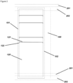
- Figures 1 to 4 show a building service element 100 of a system according to the invention in several views.
- the building service element 100 has a flat and rectangular casing 101 with vertical struts 102, which is made in a wooden frame construction and comprises a receiving region 120 with pre-assembled domestic engineering components and a shaft region 140 extending through the casing 101 from top to bottom.
- the depth of the building service element may be, for example, less than 50 cm and preferably less than 35 cm.
- a full-surface access opening 103 is formed at the front of the building service element 100, which in other variants of the invention could also be subdivided into several smaller opening possibilities, through which both the receiving region 120 and the shaft region 140 are accessible.
- the building service element 100 has two doors 104 for reversibly closing this access opening, each of which can be pivoted about a vertical axis, wherein one of the doors 104 in its closed state closes the part of the access opening 103 located in front of the receiving region 120 and the other door 104 in its closed state closes the part of the access opening 103 located in front of the shaft region 140.
- the doors can be opened by at least 90° or preferably by 180° or just under 180° to ensure the best possible accessibility.
- the doors 104 are full-surface insulated with a vacuum insulation panel 105 and are provided on the inside with a circumferential rubber seal, not shown in the Figure, which rests on the abutment surface of the casing 101 when closed.
- the internal air leakage rate should thus be kept to a value of ⁇ 5%.
- the total thickness of the doors can be less than 10 cm.
- the u-value of the entire building service element 100 should ideally be less than 0.15 W/m 2 without taking the outer building wall 200 into account.
- the shaft region 140 is open at the top and bottom respectively the casing 101 has corresponding openings in the upper and lower frame elements.
- the casing 101 is closed at the top and bottom, wherein in the corresponding regions both the frame element forming the ceiling and the frame element forming the floor are insulated against fire in such a way that the building service elements 100 as a whole meet the requirements of fire resistance class F30.
- the back of the casing 101 is open and sits directly against the existing wall of the building when the building service element 100 is installed. This leads to maximum utilization of the available space in the depth direction, which is limited due to the necessarily flat shape of the building service element.
- the building service element 100 has, for example, three pairs of fastening elements not shown in the Figures, in the form of hooks open at the bottom, which are attached on both sides of the casing 101 at the same height, once at the top, once in the middle and once at the bottom of the casing 101.
- the fastening elements are attached to the sides of the frame elements forming the side walls of the casing 101, so that no space is lost in the depth direction for fastening the building service element 100 to the outer wall 200. Rather, the building service element 100 is attached to mating contours arranged laterally of the building service element in front of the outer wall 200.
- crossbars 121 In the receiving region 120 there are a number of crossbars 121 that are held on strips 122 or directly on the casing 101.
- the domestic engineering components are attached to these crossbars 121.
- the crossbars 121 can be flexibly inserted into the casing 101 and form a shelf system by means of which the available installation space can be optimally and flexibly used for different combinations of domestic engineering components.
- the domestic engineering components can comprise the entire domestic services required to supply a residential unit. This includes heating, cooling, power supply, water supply, waste water disposal, aeration and deaeration of the residential unit, measurement of consumption, and the establishment of communication and data connections.
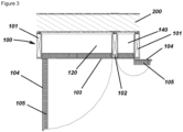
- a ventilation system 123 is provided for the aeration and deaeration of the residential unit.
- the ventilation system 123 comprises an outside and supply air duct 124 and an exhaust and outgoing air duct 125, which are thermally coupled to a cross-flow heat exchanger 126, which in other variants of the invention can also be replaced by another heat exchanger, for heat recovery.
- a bypass line to the outside and supply air duct 124, which is not shown in the Figure, can bypass the cross-flow heat exchanger 126 for winter operation.
- the cross-flow heat exchanger 126 is preferably designed to achieve a heat recovery coefficient of ⁇ 80% in operation.
- the power efficiency of the ventilation system 123 in operation shall preferably reach ⁇ 0.4 Wh/m 3 .
- the ducts 124 and 125 terminate at a grilled ventilation opening 106 in the door 104 in front of the receiving region 120, which is provided with a circumferential rubber seal to prevent unwanted air exchange next to the ducts.
- ducts 124 and 125 terminate at connectors not shown in the Figure, which are stationary mounted to the casing 101.
- the ventilation system 123 is arranged in the upper part of the receiving region 120 and the connections 135 on the inside of the ducts 124 and 125 are located under the ceiling of the casing 101. In this way, when the building service element 100 is in use, they can be connected directly to ducts that run into the residential unit through core holes in the outer wall of the building arranged under a storey ceiling.
- the ventilation system 123 may further comprise control electronics, flaps, valves, fans, air filters, silencers, humidity sensors and/or CO 2 -sensors. However, all of these elements are not shown in the Figures for reasons of clarity.
- the ventilation system 123 may be configured to control air flow rates via CO 2 -sensors and/or humidity sensors. Both the humidity and the CO 2 -content in the flat can thus be monitored and controlled.
- a hot water tank 136 is arranged below the ventilation system 123 in the receiving region 120.
- its capacity can be at least 120 to 160 litres in order to be able to cover all typical flat sizes in apartment buildings.
- the hot water tank 136 meets the requirements of ErP class A with heat losses of ⁇ 1.5 W/K.
- An electric heating register 128 allows heating of both the air flow in the outdoor and supply air duct 124 for winter operation and the water in the hot water tank 136 as required. Hot water can be supplied to the flat directly from the hot water tank or indirectly via a flat station with heat exchanger.
- the exhaust and outgoing air duct 125 of the ventilation system 123 and the hot water tank 136 are additionally coupled via a heat transfer circuit 129, whereby exhaust heat from the residential unit can be used to heat the water in the hot water tank.
- the target for the effective performance of the heat transfer circuit 129 is a COP (Air7 - Water35) in the range of 3.5 to 4.5 respectively ⁇ s (ETAs) - EE-requirements in % low temperature 35°C of at least 140 %.
- the exhaust air heat source improves the COP compared to an outdoor air heat pump.
- Some and possibly even all of the pipes, valves and ducts of the building service element 100 are preferably thermally insulated.
- the domestic engineering components mentioned are preferably set so that their output is sufficient for a flat with 3-5 people respectively 60-100 m 2 of living space. With this output, most common flats or areas in apartment buildings or other buildings can be covered and supplied. This means that the prerequisites for standardization are fulfilled.
- this means that the domestic engineering components mentioned are preferably designed for a nominal air flow rate according to DIN 1946-6 of 60 to 100 m 3 /h, ventilation for moisture protection according to DIN 1946-6 of 30 to 50 m 3 /h, a heating load demand of 900 to 1,500 W/h respectively up to 20 W/m 2 , and/or a domestic hot water energy demand of 200 to 300 W/h.
- domestic engineering components which in one embodiment may be installed in the building service element 100, include components of an electric auxiliary heating system, an electric frost protection system, temperature sensors on the inside and/or outside of the casing 101, thermostats, silencers, as well as a control unit with, for example, interfaces for remote control and remote reading, consumption recording, control software for the domestic engineering components, and possibly a screen with information and control.
- the hot water tank 136 comprises two connections 127 for connection to risers 141 respectively hot water pipes 142 leading into the living unit, which are routed through the shaft region 140 after the building service element 100 has been fixed in front of the outer wall 200.
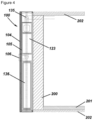
- Figures 5 and 6 show a window opening 203 in the outer wall 200 of a building provided with a soffit element 300.
- the soffit element 300 has the shape of a rectangular frame and is composed of four side panels 301, each covering one side of the window opening 203. It is inserted into the window opening 203 from the inside of the building.
- the depth of the side panels 301 is greater than the depth of the outer wall 200 or window opening 203, so that the side panels 301 also conceal a gap 220 between facade elements 400 arranged in front of the outer wall 200 and the outer wall 200 in relation to the window opening 203.
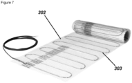
- the side panels 301 of the soffit element 300 are backed on their side facing away from the window opening 203 with a heating mat 302 as shown in Figure 7 , which have electrical heating elements 303 in the form of meandering resistance wires.
- a heating mat 302 as shown in Figure 7 , which have electrical heating elements 303 in the form of meandering resistance wires.
- all four side panels 301 are backed in this manner, but three or fewer side panels 301 may also be backed with heating elements in other variants of the invention.
- these heating elements 303 are connected to a distributor in the building service element 100.
- Suitable heating mats have, for example, heating powers of between 200 and 500 W/m 2 respectively can be set to a maximum temperature of between 40°C and 60°C.
- the heating soffit element 300 can also be a prefabricated part which, together with the ventilation system 123 of the building service element, forms a system for temperature control of a residential unit.
- the soffit elements 300 should cover peak loads, while basic loads are preferably covered by the normally more energy-efficient ventilation system 123. They can be quickly and easily installed in the window opening 203 using, for example, plug-in or snap-in connections.
- the heated soffits are auxiliary heaters used to support and provide peak load coverage for the supply air heating via the ventilation system. While the air heating can preferably cover a basic load up to, for example, 18°C inside temperature, the heated soffits can individually supplement the heating requirement, for example in connection with room-by-room thermostats. In this way, differently warm rooms can be made possible, with recourse to pleasant radiant heat directly at the thermal weak point, the window.
- windows 204 and jalousies 205 are inserted into them, as can be seen in Figures 5 and 6 .
Landscapes
- Engineering & Computer Science (AREA)
- General Engineering & Computer Science (AREA)
- Chemical & Material Sciences (AREA)
- Combustion & Propulsion (AREA)
- Mechanical Engineering (AREA)
- Thermal Sciences (AREA)
- Physics & Mathematics (AREA)
- Architecture (AREA)
- Life Sciences & Earth Sciences (AREA)
- Sustainable Development (AREA)
- Civil Engineering (AREA)
- Structural Engineering (AREA)
- Building Environments (AREA)
Claims (14)
- Ein System umfassend:ein Haustechnikelement (100) zur Montage vor einer Außenwand (200) eines Gebäudes und, insbesondere, eines Bestandsgebäudes;wobei das Haustechnikelement (100) ein Gehäuse (101) aufweist, das mindestens einen Aufnahmebereich (120) mit vormontierten Haustechnikkomponenten und einen das Gehäuse (101) von oben bis unten durchlaufenden Schachtbereich (140) umfasst, wobei der Aufnahmebereich (120) und der Schachtbereich (140) nebeneinander angeordnet sind, und wobei das Haustechnikelement (100) an der Vorderseite eine großflächige oder vollflächige Zugangsöffnung (103) aufweist, durch die sowohl der Aufnahmebereich (120) als auch der Schachtbereich (140) zugänglich sind, und die durch eine oder mehrere Verschlusselemente reversibel verschlossen ist (104);dadurch gekennzeichnet,dass das System des Weiteren umfasst:wenigstens ein Laibungselement (300) zum Einsetzen in eine Tür- oder Fensteröffnung (203) in der Außenwand (200) des Gebäudes,wobei das Laibungselement (300) zu je einer Kante der Tür- oder Fensteröffnung (203) korrespondierende Seitentafeln (301) aufweist, wobei die Seitentafeln (301) mit einer großflächig daran wirkenden Heizung hinterkleidet sind, wobei die Heizung zur Energieversorgung mit einer Haustechnikkomponente des Haustechnikelements (100) verbunden ist, wobei es sich bei der Heizung vorzugsweise um eine Heizmatte (302) handelt, deren Heizelemente als elektrische Widerstandsheizungen ausgebildet sind.
- System nach Anspruch 1, dadurch gekennzeichnet, dass es sich bei den Verschlusselementen (104) um eine oder mehrere um eine senkrechte Achse schwenkbare Türen oder um eine waagrechte Achse schwenkbare Klappen handelt, und/oder dass ein dem Aufnahmebereich (120) vorgelagerter Teil der Zugangsöffnung (103) durch ein erstes Verschlusselement (104) und ein dem Schachtbereich (140) vorgelagerter Teil der Zugangsöffnung (103) durch ein weiteres Verschlusselement (104) verschlossen ist.
- System nach einem der vorhergehenden Ansprüche, dadurch gekennzeichnet, dass das oder die Verschlusselemente (104) wärmegedämmt sind, insbesondere eine Vakuumdämmung (105) aufweisen; und/oder dass zwischen den Verschlusselementen (104) und dem Gehäuse (101) eine luftdichte bzw. zumindest winddichte Dichtung verläuft.
- System nach einem der vorhergehenden Ansprüche, dadurch gekennzeichnet, dass das Gehäuse (101) eine flache rechteckige Gestalt hat, wobei vorzugsweise die Länge der kürzeren Seite des Gehäuses (101) mindestens das dreifache von dessen Tiefe und/oder die Länge der längeren Seite des Gehäuses (101) mindestens das fünffache von dessen Tiefe beträgt.
- System nach einem der vorhergehenden Ansprüche, dadurch gekennzeichnet, dass der Schachtbereich (140) nach oben und unten offen ist und das Gehäuse (101) entsprechende Durchgänge im Boden bzw. der Decke aufweist.
- System nach einem der vorhergehenden Ansprüche, dadurch gekennzeichnet, dass der Aufnahmebereich (120) nach oben und unten geschlossen ist und der Boden und/oder die Decke im Bereich des Aufnahmebereichs (120) brandschutzisoliert sind.
- System nach einem der vorhergehenden Ansprüche, dadurch gekennzeichnet, dass das Haustechnikelement (100) zwei Schachtbereiche (140) links und rechts des Aufnahmebereichs (120) umfasst.
- System nach einem der vorhergehenden Ansprüche, dadurch gekennzeichnet, dass die Rückseite des Haustechnikelements (100) zumindest bereichsweise, insbesondere im Bereich des Aufnahmebereichs (120) offen ist.
- System nach einem der vorhergehenden Ansprüche, dadurch gekennzeichnet, dass das Haustechnikelement (100) wenigstens ein Paar an links und rechts am Gehäuse (101), vorzugsweise seitlich des Gehäuses (101) auf gleicher Höhe angeordneten Befestigungselementen aufweist, um es vor der Außenwand (200) des Gebäudes befestigen zu können, wobei es sich bei den Befestigungselementen vorzugsweise um nach unten offene Einhängekonturen handelt.
- System nach einem der vorhergehenden Ansprüche, dadurch gekennzeichnet, dass die Haustechnikkomponenten an vertikalen Strukturelementen (102) des Gehäuses (101) befestigt sind, wobei das Haustechnikelement (100) insbesondere ein Regalsystem mit flexibel in das Gehäuse (101) einsetzbaren Traversen (121) umfasst, an denen die Haustechnikkomponenten befestigt sind, wobei die Traversen (121) an den vertikalen Strukturelementen des Gehäuses (101) befestigt sind.
- System nach einem der vorhergehenden Ansprüche, dadurch gekennzeichnet, dass die Haustechnikkomponenten eine Be- und Endlüftungsanlage umfassen, die vorzugsweise einen Wärmetauscher (126) zur Wärmerückgewinnung aufweist, oder eine Abluftanlage (123) umfassen.
- System nach Anspruch 11, dadurch gekennzeichnet, dass wenigstens ein Verschlusselement (104) eine Lüftungsöffnung (106) aufweist, die insbesondere nach Lage und Größe an ein zugeordnetes Luftführungselement (124, 125) der Lüftungsanlage (123) angepasst ist, wobei vorzugsweise vorgesehen ist, dass am Verschlusselement (104) oder der Lüftungsanlage (123) ein Dichtelement ausgebildet ist, das bei geschlossener Tür (104) eine Schnittstelle zwischen Lüftungsöffnung (106) und zugeordnetem Luftführungselement (124, 125) abdichtet.
- System nach Anspruch 11 oder 12, dadurch gekennzeichnet, dass die Haustechnikkomponenten ferner einen Warmwasserspeicher (136) umfassen, wobei insbesondere vorgesehen sein kann, dass die Lüftungsanlage (123) und der Warmwasserspeicher (136) über eine Wärmepumpe (129), insbesondere eine Ab- und/oder Fortluftwärmepumpe thermisch verbunden sind.
- System nach einem der vorhergehenden Ansprüche, dadurch gekennzeichnet, dass zumindest ein Teil der Haustechnikelemente (100) Anschlüsse zur Verbindung des Haustechnikelements (100) mit einer im Schachtbereich (140) verlaufenden oder in eine Wohneinheit des Gebäudes führenden Leitung (141, 142), die vorzugsweise ortsfest im Haustechnikelement (100) angeordnet sind.
Applications Claiming Priority (3)
| Application Number | Priority Date | Filing Date | Title |
|---|---|---|---|
| DE102021107398.7A DE102021107398A1 (de) | 2021-03-24 | 2021-03-24 | Verfahren zur energetischen Gebäudesanierung |
| DE102021118086.4A DE102021118086A1 (de) | 2021-07-13 | 2021-07-13 | Haustechnikelement |
| PCT/EP2022/057105 WO2022200198A1 (en) | 2021-03-24 | 2022-03-18 | Building service element |
Publications (3)
| Publication Number | Publication Date |
|---|---|
| EP4121618A1 EP4121618A1 (de) | 2023-01-25 |
| EP4121618B1 true EP4121618B1 (de) | 2024-07-31 |
| EP4121618C0 EP4121618C0 (de) | 2024-07-31 |
Family
ID=81327644
Family Applications (1)
| Application Number | Title | Priority Date | Filing Date |
|---|---|---|---|
| EP22716878.8A Active EP4121618B1 (de) | 2021-03-24 | 2022-03-18 | Gebäudeserviceelement |
Country Status (2)
| Country | Link |
|---|---|
| EP (1) | EP4121618B1 (de) |
| WO (1) | WO2022200198A1 (de) |
Family Cites Families (4)
| Publication number | Priority date | Publication date | Assignee | Title |
|---|---|---|---|---|
| JPH0842123A (ja) * | 1994-07-28 | 1996-02-13 | Yoshihito Yamashita | 配管設備ユニットおよびこれを用いた配管設備施工方法 |
| FI126876B (fi) * | 2012-08-14 | 2017-07-14 | Pilaster Oy | Talotekniikkamoduuli |
| JP6324106B2 (ja) * | 2014-02-24 | 2018-05-16 | 株式会社長谷工コーポレーション | 共同住宅のメーターボックス |
| DE202017104624U1 (de) * | 2017-08-02 | 2017-09-29 | Thomas Seidl | Elektrische Flächenheizung und Baukörper mit einer solchen Flächenheizung |
-
2022
- 2022-03-18 EP EP22716878.8A patent/EP4121618B1/de active Active
- 2022-03-18 WO PCT/EP2022/057105 patent/WO2022200198A1/en not_active Ceased
Also Published As
| Publication number | Publication date |
|---|---|
| WO2022200198A1 (en) | 2022-09-29 |
| EP4121618C0 (de) | 2024-07-31 |
| EP4121618A1 (de) | 2023-01-25 |
Similar Documents
| Publication | Publication Date | Title |
|---|---|---|
| Roberts | Altering existing buildings in the UK | |
| CA2322556C (en) | Air conditioning system for buildings and air-conditioned building, especially a zero energy house | |
| US20120028563A1 (en) | Energy efficient building environmental control apparatus and method | |
| Dodoo | Primary energy and economic implications of ventilation heat recovery for a multi-family building in a Nordic climate | |
| US20120108158A1 (en) | Solar energy intercept and waste heat recovery system | |
| EP2169330A1 (de) | Heisswasserversorgungssystem für haus | |
| US20210247077A1 (en) | Facade Panel Conditioning System | |
| EP4121618B1 (de) | Gebäudeserviceelement | |
| FI101493B (fi) | Rakennus | |
| CA2841018C (en) | Efficient house: an efficient, healthful and durable building system using differential airflow and heat control across an air permeable heat reflective external envelope assembly | |
| JP2023024227A (ja) | 建造物 | |
| DE102021118086A1 (de) | Haustechnikelement | |
| KR20130085675A (ko) | 중앙식 건물환기장치 | |
| EP2792802A1 (de) | Modulare Einheit | |
| EP4121617B1 (de) | Separate gebäudeserviceelemente und schachtelemente | |
| Kwiatkowski et al. | Dormitory thermal retrofitting to nZEB standard | |
| JP7432954B2 (ja) | 建造物 | |
| Stecher et al. | Design and Performance of the Smith House, A Passive House. | |
| Sobczyk et al. | Thermal comfort in a passive solar building | |
| JP5437727B2 (ja) | ダブルスキン外壁を備えた建物 | |
| Croxford et al. | Retrofitting to Near Passivhaus Standard | |
| Coydon et al. | Rapid Retrofit Solutions Integrating HVAC into Prefabricated EWIS Systems | |
| Rode et al. | Performance of the Low-energy House in Sisimiut | |
| Siviour et al. | A summary assessment of the Capenhurst home. | |
| Carbonaro et al. | Neighborhood Renew |
Legal Events
| Date | Code | Title | Description |
|---|---|---|---|
| STAA | Information on the status of an ep patent application or granted ep patent |
Free format text: STATUS: UNKNOWN |
|
| STAA | Information on the status of an ep patent application or granted ep patent |
Free format text: STATUS: THE INTERNATIONAL PUBLICATION HAS BEEN MADE |
|
| PUAI | Public reference made under article 153(3) epc to a published international application that has entered the european phase |
Free format text: ORIGINAL CODE: 0009012 |
|
| STAA | Information on the status of an ep patent application or granted ep patent |
Free format text: STATUS: REQUEST FOR EXAMINATION WAS MADE |
|
| 17P | Request for examination filed |
Effective date: 20221021 |
|
| AK | Designated contracting states |
Kind code of ref document: A1 Designated state(s): AL AT BE BG CH CY CZ DE DK EE ES FI FR GB GR HR HU IE IS IT LI LT LU LV MC MK MT NL NO PL PT RO RS SE SI SK SM TR |
|
| RIC1 | Information provided on ipc code assigned before grant |
Ipc: F24H 4/06 20060101ALN20240311BHEP Ipc: F24H 4/04 20060101ALN20240311BHEP Ipc: F24H 3/02 20220101ALN20240311BHEP Ipc: F24H 1/20 20220101ALN20240311BHEP Ipc: F24F 110/70 20180101ALN20240311BHEP Ipc: F24F 110/20 20180101ALN20240311BHEP Ipc: F24F 12/00 20060101ALN20240311BHEP Ipc: F24F 11/72 20180101ALN20240311BHEP Ipc: F24F 5/00 20060101ALN20240311BHEP Ipc: F24D 5/12 20060101ALN20240311BHEP Ipc: F24D 13/02 20060101ALI20240311BHEP Ipc: E04F 17/08 20060101AFI20240311BHEP |
|
| RIC1 | Information provided on ipc code assigned before grant |
Ipc: F24H 4/06 20060101ALN20240320BHEP Ipc: F24H 4/04 20060101ALN20240320BHEP Ipc: F24H 3/02 20220101ALN20240320BHEP Ipc: F24H 1/20 20220101ALN20240320BHEP Ipc: F24F 110/70 20180101ALN20240320BHEP Ipc: F24F 110/20 20180101ALN20240320BHEP Ipc: F24F 12/00 20060101ALN20240320BHEP Ipc: F24F 11/72 20180101ALN20240320BHEP Ipc: F24F 5/00 20060101ALN20240320BHEP Ipc: F24D 5/12 20060101ALN20240320BHEP Ipc: F24D 13/02 20060101ALI20240320BHEP Ipc: E04F 17/08 20060101AFI20240320BHEP |
|
| GRAP | Despatch of communication of intention to grant a patent |
Free format text: ORIGINAL CODE: EPIDOSNIGR1 |
|
| STAA | Information on the status of an ep patent application or granted ep patent |
Free format text: STATUS: GRANT OF PATENT IS INTENDED |
|
| INTG | Intention to grant announced |
Effective date: 20240502 |
|
| GRAS | Grant fee paid |
Free format text: ORIGINAL CODE: EPIDOSNIGR3 |
|
| GRAA | (expected) grant |
Free format text: ORIGINAL CODE: 0009210 |
|
| STAA | Information on the status of an ep patent application or granted ep patent |
Free format text: STATUS: THE PATENT HAS BEEN GRANTED |
|
| DAV | Request for validation of the european patent (deleted) | ||
| DAX | Request for extension of the european patent (deleted) | ||
| AK | Designated contracting states |
Kind code of ref document: B1 Designated state(s): AL AT BE BG CH CY CZ DE DK EE ES FI FR GB GR HR HU IE IS IT LI LT LU LV MC MK MT NL NO PL PT RO RS SE SI SK SM TR |
|
| REG | Reference to a national code |
Ref country code: CH Ref legal event code: EP Ref country code: GB Ref legal event code: FG4D |
|
| REG | Reference to a national code |
Ref country code: DE Ref legal event code: R096 Ref document number: 602022005013 Country of ref document: DE |
|
| REG | Reference to a national code |
Ref country code: IE Ref legal event code: FG4D |
|
| U01 | Request for unitary effect filed |
Effective date: 20240731 |
|
| U07 | Unitary effect registered |
Designated state(s): AT BE BG DE DK EE FI FR IT LT LU LV MT NL PT SE SI Effective date: 20240813 |
|
| PG25 | Lapsed in a contracting state [announced via postgrant information from national office to epo] |
Ref country code: NO Free format text: LAPSE BECAUSE OF FAILURE TO SUBMIT A TRANSLATION OF THE DESCRIPTION OR TO PAY THE FEE WITHIN THE PRESCRIBED TIME-LIMIT Effective date: 20241031 |
|
| PG25 | Lapsed in a contracting state [announced via postgrant information from national office to epo] |
Ref country code: GR Free format text: LAPSE BECAUSE OF FAILURE TO SUBMIT A TRANSLATION OF THE DESCRIPTION OR TO PAY THE FEE WITHIN THE PRESCRIBED TIME-LIMIT Effective date: 20241101 Ref country code: PL Free format text: LAPSE BECAUSE OF FAILURE TO SUBMIT A TRANSLATION OF THE DESCRIPTION OR TO PAY THE FEE WITHIN THE PRESCRIBED TIME-LIMIT Effective date: 20240731 |
|
| PG25 | Lapsed in a contracting state [announced via postgrant information from national office to epo] |
Ref country code: IS Free format text: LAPSE BECAUSE OF FAILURE TO SUBMIT A TRANSLATION OF THE DESCRIPTION OR TO PAY THE FEE WITHIN THE PRESCRIBED TIME-LIMIT Effective date: 20241130 |
|
| PG25 | Lapsed in a contracting state [announced via postgrant information from national office to epo] |
Ref country code: HR Free format text: LAPSE BECAUSE OF FAILURE TO SUBMIT A TRANSLATION OF THE DESCRIPTION OR TO PAY THE FEE WITHIN THE PRESCRIBED TIME-LIMIT Effective date: 20240731 |
|
| PG25 | Lapsed in a contracting state [announced via postgrant information from national office to epo] |
Ref country code: ES Free format text: LAPSE BECAUSE OF FAILURE TO SUBMIT A TRANSLATION OF THE DESCRIPTION OR TO PAY THE FEE WITHIN THE PRESCRIBED TIME-LIMIT Effective date: 20240731 Ref country code: RS Free format text: LAPSE BECAUSE OF FAILURE TO SUBMIT A TRANSLATION OF THE DESCRIPTION OR TO PAY THE FEE WITHIN THE PRESCRIBED TIME-LIMIT Effective date: 20241031 |
|
| PG25 | Lapsed in a contracting state [announced via postgrant information from national office to epo] |
Ref country code: RS Free format text: LAPSE BECAUSE OF FAILURE TO SUBMIT A TRANSLATION OF THE DESCRIPTION OR TO PAY THE FEE WITHIN THE PRESCRIBED TIME-LIMIT Effective date: 20241031 Ref country code: PL Free format text: LAPSE BECAUSE OF FAILURE TO SUBMIT A TRANSLATION OF THE DESCRIPTION OR TO PAY THE FEE WITHIN THE PRESCRIBED TIME-LIMIT Effective date: 20240731 Ref country code: NO Free format text: LAPSE BECAUSE OF FAILURE TO SUBMIT A TRANSLATION OF THE DESCRIPTION OR TO PAY THE FEE WITHIN THE PRESCRIBED TIME-LIMIT Effective date: 20241031 Ref country code: IS Free format text: LAPSE BECAUSE OF FAILURE TO SUBMIT A TRANSLATION OF THE DESCRIPTION OR TO PAY THE FEE WITHIN THE PRESCRIBED TIME-LIMIT Effective date: 20241130 Ref country code: HR Free format text: LAPSE BECAUSE OF FAILURE TO SUBMIT A TRANSLATION OF THE DESCRIPTION OR TO PAY THE FEE WITHIN THE PRESCRIBED TIME-LIMIT Effective date: 20240731 Ref country code: GR Free format text: LAPSE BECAUSE OF FAILURE TO SUBMIT A TRANSLATION OF THE DESCRIPTION OR TO PAY THE FEE WITHIN THE PRESCRIBED TIME-LIMIT Effective date: 20241101 Ref country code: ES Free format text: LAPSE BECAUSE OF FAILURE TO SUBMIT A TRANSLATION OF THE DESCRIPTION OR TO PAY THE FEE WITHIN THE PRESCRIBED TIME-LIMIT Effective date: 20240731 |
|
| PG25 | Lapsed in a contracting state [announced via postgrant information from national office to epo] |
Ref country code: SM Free format text: LAPSE BECAUSE OF FAILURE TO SUBMIT A TRANSLATION OF THE DESCRIPTION OR TO PAY THE FEE WITHIN THE PRESCRIBED TIME-LIMIT Effective date: 20240731 |
|
| PG25 | Lapsed in a contracting state [announced via postgrant information from national office to epo] |
Ref country code: CZ Free format text: LAPSE BECAUSE OF FAILURE TO SUBMIT A TRANSLATION OF THE DESCRIPTION OR TO PAY THE FEE WITHIN THE PRESCRIBED TIME-LIMIT Effective date: 20240731 |
|
| PG25 | Lapsed in a contracting state [announced via postgrant information from national office to epo] |
Ref country code: SK Free format text: LAPSE BECAUSE OF FAILURE TO SUBMIT A TRANSLATION OF THE DESCRIPTION OR TO PAY THE FEE WITHIN THE PRESCRIBED TIME-LIMIT Effective date: 20240731 |
|
| U20 | Renewal fee for the european patent with unitary effect paid |
Year of fee payment: 4 Effective date: 20250325 |
|
| PLBE | No opposition filed within time limit |
Free format text: ORIGINAL CODE: 0009261 |
|
| STAA | Information on the status of an ep patent application or granted ep patent |
Free format text: STATUS: NO OPPOSITION FILED WITHIN TIME LIMIT |
|
| 26N | No opposition filed |
Effective date: 20250501 |
|
| PG25 | Lapsed in a contracting state [announced via postgrant information from national office to epo] |
Ref country code: MC Free format text: LAPSE BECAUSE OF FAILURE TO SUBMIT A TRANSLATION OF THE DESCRIPTION OR TO PAY THE FEE WITHIN THE PRESCRIBED TIME-LIMIT Effective date: 20240731 |
|
| REG | Reference to a national code |
Ref country code: CH Ref legal event code: H13 Free format text: ST27 STATUS EVENT CODE: U-0-0-H10-H13 (AS PROVIDED BY THE NATIONAL OFFICE) Effective date: 20251024 |
|
| U1N | Appointed representative for the unitary patent procedure changed after the registration of the unitary effect |
Representative=s name: LORENZ SEIDLER GOSSEL PART. MBB; DE |
|
| PG25 | Lapsed in a contracting state [announced via postgrant information from national office to epo] |
Ref country code: CH Free format text: LAPSE BECAUSE OF NON-PAYMENT OF DUE FEES Effective date: 20250331 |
|
| PG25 | Lapsed in a contracting state [announced via postgrant information from national office to epo] |
Ref country code: IE Free format text: LAPSE BECAUSE OF NON-PAYMENT OF DUE FEES Effective date: 20250318 |