EP4120946B1 - Verfahren und vorrichtung zur unterstützung eines invasiven eingriffs an einem menschlichen oder tierischen organ - Google Patents
Verfahren und vorrichtung zur unterstützung eines invasiven eingriffs an einem menschlichen oder tierischen organ Download PDFInfo
- Publication number
- EP4120946B1 EP4120946B1 EP21711598.9A EP21711598A EP4120946B1 EP 4120946 B1 EP4120946 B1 EP 4120946B1 EP 21711598 A EP21711598 A EP 21711598A EP 4120946 B1 EP4120946 B1 EP 4120946B1
- Authority
- EP
- European Patent Office
- Prior art keywords
- plane
- dimensional model
- entry point
- organ
- displaying
- Prior art date
- Legal status (The legal status is an assumption and is not a legal conclusion. Google has not performed a legal analysis and makes no representation as to the accuracy of the status listed.)
- Active
Links
Images


Classifications
-
- A—HUMAN NECESSITIES
- A61—MEDICAL OR VETERINARY SCIENCE; HYGIENE
- A61B—DIAGNOSIS; SURGERY; IDENTIFICATION
- A61B34/00—Computer-aided surgery; Manipulators or robots specially adapted for use in surgery
- A61B34/10—Computer-aided planning, simulation or modelling of surgical operations
-
- A—HUMAN NECESSITIES
- A61—MEDICAL OR VETERINARY SCIENCE; HYGIENE
- A61B—DIAGNOSIS; SURGERY; IDENTIFICATION
- A61B17/00—Surgical instruments, devices or methods
- A61B17/56—Surgical instruments or methods for treatment of bones or joints; Devices specially adapted therefor
- A61B17/58—Surgical instruments or methods for treatment of bones or joints; Devices specially adapted therefor for osteosynthesis, e.g. bone plates, screws or setting implements
- A61B17/68—Internal fixation devices, including fasteners and spinal fixators, even if a part thereof projects from the skin
- A61B17/70—Spinal positioners or stabilisers, e.g. stabilisers comprising fluid filler in an implant
- A61B17/7001—Screws or hooks combined with longitudinal elements which do not contact vertebrae
-
- G—PHYSICS
- G06—COMPUTING OR CALCULATING; COUNTING
- G06T—IMAGE DATA PROCESSING OR GENERATION, IN GENERAL
- G06T17/00—Three-dimensional [3D] modelling for computer graphics
-
- G—PHYSICS
- G06—COMPUTING OR CALCULATING; COUNTING
- G06T—IMAGE DATA PROCESSING OR GENERATION, IN GENERAL
- G06T19/00—Manipulating three-dimensional [3D] models or images for computer graphics
-
- A—HUMAN NECESSITIES
- A61—MEDICAL OR VETERINARY SCIENCE; HYGIENE
- A61B—DIAGNOSIS; SURGERY; IDENTIFICATION
- A61B34/00—Computer-aided surgery; Manipulators or robots specially adapted for use in surgery
- A61B34/10—Computer-aided planning, simulation or modelling of surgical operations
- A61B2034/101—Computer-aided simulation of surgical operations
- A61B2034/105—Modelling of the patient, e.g. for ligaments or bones
-
- A—HUMAN NECESSITIES
- A61—MEDICAL OR VETERINARY SCIENCE; HYGIENE
- A61B—DIAGNOSIS; SURGERY; IDENTIFICATION
- A61B34/00—Computer-aided surgery; Manipulators or robots specially adapted for use in surgery
- A61B34/10—Computer-aided planning, simulation or modelling of surgical operations
- A61B2034/107—Visualisation of planned trajectories or target regions
-
- A—HUMAN NECESSITIES
- A61—MEDICAL OR VETERINARY SCIENCE; HYGIENE
- A61B—DIAGNOSIS; SURGERY; IDENTIFICATION
- A61B34/00—Computer-aided surgery; Manipulators or robots specially adapted for use in surgery
- A61B34/10—Computer-aided planning, simulation or modelling of surgical operations
- A61B2034/108—Computer aided selection or customisation of medical implants or cutting guides
-
- A—HUMAN NECESSITIES
- A61—MEDICAL OR VETERINARY SCIENCE; HYGIENE
- A61B—DIAGNOSIS; SURGERY; IDENTIFICATION
- A61B34/00—Computer-aided surgery; Manipulators or robots specially adapted for use in surgery
- A61B34/25—User interfaces for surgical systems
-
- G—PHYSICS
- G06—COMPUTING OR CALCULATING; COUNTING
- G06T—IMAGE DATA PROCESSING OR GENERATION, IN GENERAL
- G06T2210/00—Indexing scheme for image generation or computer graphics
- G06T2210/41—Medical
Definitions
- the present invention relates to a method and a device for assisting an invasive intervention on a human or animal organ, for example to plan the placement of spinal implants.
- the present invention can be used, in particular, for surgery relating to a substantially rigid human or animal anatomical part (that is to say an anatomical part which does not deform or deforms little under moderate pressure).
- a substantially rigid human or animal anatomical part that is to say an anatomical part which does not deform or deforms little under moderate pressure.
- embodiments of the invention relate to preparation for spinal surgery, for example preparation for insertion of pedicle screws into one or more vertebrae.
- the internal skeletal structure of a mammal, human or animal is made up of around a hundred bones.
- the spine is a chain of bones called vertebrae allowing flexibility and movement, while protecting the nerve and vascular structures found in and around the spine.
- the spine begins at the base of the skull and extends to the pelvis. It is made up of four regions: cervical, thoracic, lumbar and sacral.
- FIGS. 1A and 1B respectively represent a top view and a side view of a thoracic vertebra 1.
- the vertebra 1 comprises a vertebral body 2 facing forward, a vertebral foramen 3 in the form of a hole allowing the spinal cord to pass , two transverse processes 4A and 4B oriented backwards and outwards, a spinous process 5 between the transverse processes 4A and 4B and oriented downwards, two blades 6A and 6B which connect the transverse processes 4A and 4B to the process spinous 5, two pedicles 7A and 7B which connect the vertebral body 2 to the transverse processes 4A and 4B, two upper articular facets 8A (not shown) and 8B and two lower articular facets 9A (not shown) and 9B which allow the articulation of vertebra 1 with an adjacent vertebra (they are stacked on top of each other).
- Normal or ideal spinal alignment can be disrupted following trauma or disease (e.g. scoliosis).
- the vertebrae can then rotate around three axes (X, Y, Z), sometimes requiring surgical intervention in order to correct the anomalies and regain ideal or, at the very least, improved vertebral alignment.
- two or more adjacent vertebrae are usually fused together by a process in which a surgeon opens the patient, usually from the back, determines an entry point 10 and drills holes 11 in the pedicles 7A and 7B of vertebra 1 and one or more other neighboring vertebrae.
- the holes are drilled with an axial angle alpha ⁇ (the angle relative to the vertical XZ plane) and a sagittal angle beta ⁇ (the angle relative to the XY plane), as shown in the Figures 1A and 1B respectively.
- Pedicle screws 12 comprising U-shaped ends 13 (but potentially with other shapes) can then be inserted into the holes 11. For reasons of clarity of the Figure 1A , a single entry point 10, hole 11, pedicle screw 12, and tip 13 are shown.
- Each end 13 receives a connecting element (not shown), for example a rod, which makes it possible to connect several screws (of several vertebrae) together and thus reduce deformation and fuse vertebrae together.
- a connecting element for example a rod
- the holes 11 drilled and the pedicle screws 12 placed in the vertebrae must be carefully positioned and aligned so as not to injure the adjacent nervous and vascular structures, or even cause the death of the patient. If the screws are incorrectly positioned, a second operation must be carried out, entailing additional costs and risks.
- the position and orientation of a pedicle screw are determined in a 3D analysis step of data obtained during a preoperative phase. After having defined this position and orientation, the entry point of the pedicle screw into the vertebra is deduced.
- landmarks on the vertebra e.g.
- the practitioner can, during surgery, determine the entry point on the vertebra and, depending on the entry point thus determined and the orientation of the pedicle screw determined during the preoperative phase, pierce the vertebra to install the pedicle screw.
- the present invention addresses this problem.
- the simulator allows users to import patient-specific CT or MRI scans as DICOM data sets, and can be fully integrated with picture archiving and communications (PACS) servers. Users can then use 2D orthographic views as well as 3D renderings of a patient's spine to take measurements for surgery.
- PES picture archiving and communications
- Screw placement can then be assessed by calculating the percentage of cortical and cancellous bone in contact with the surface of each screw, and displayed graphically. Additionally, the position of each screw pattern is compared to the patient's CT scan data to map the pixel intensities of the Hounsfield unit directly onto the surface of the screw pattern.
- the invention proposes to determine an entry point of an element, on a 3D model of the organ in which this element must be inserted, then determine the orientation in which this element must be inserted in order to optimize its position and orientation.
- the method according to the invention thus allows precise positioning of an element by first choosing the entry point of this element according to criteria ensuring, in convenient, easy determination of this entry point, then choosing the orientation in which it should be inserted.
- the method further comprises the construction of said three-dimensional model.
- Such a construction can be carried out, for example, by digital tomography.
- the method further comprises displaying a representation of at least part of said three-dimensional model, the display of at least part of said three-dimensional model allowing the display and/or determination of at least one entry point.
- At least two entry points are determined, said plurality of axes being defined by the intersection of a first plane comprising a straight line passing through said at least two entry points and a second plane including an entry point.
- Said second plane may comprise a straight line perpendicular to said first plane.
- the method further comprises displaying a sectional view of said three-dimensional model according to said first plane, said first plane forming a first angle with respect to a first reference linked to said three-dimensional model.
- the method comprises a modification of the value of said first angle, the display of a sectional view along said first plane being adapted to said modification of said first angle.
- the method further comprises displaying a sectional view of said three-dimensional model according to said second plane, said second plane forming a second angle with respect to a second reference linked to said three-dimensional model.
- the method comprises a modification of the value of said second angle, the display of a sectional view along said second plane being adapted to said modification of said second angle.
- the method comprises moving at least one entry point defined on said three-dimensional model.
- the method comprises measuring a diameter and/or a length of an element to be inserted according to a determined entry point, a determined insertion axis and said three-dimensional model.
- Said organ is, for example, a vertebra and said element to be inserted is, for example, a pedicle screw.
- the invention also relates to a device for assisting an invasive intervention on a human or animal organ, the device comprising a processing unit configured to carry out each of the steps of the method described above.
- a computer program implementing all or part of the method described above, installed on pre-existing equipment, is in itself advantageous, since it provides assistance to help a user identify a desired position of a element in an organ.
- the present invention also targets a computer program comprising instructions for implementing the method described above, when this program is executed by a processor.
- This program may use any programming language (e.g., object language or other) and be in the form of interpretable source code, partially compiled code, or fully compiled code.
- object language e.g., object language or other
- Another aspect relates to a non-transitory storage medium of a computer executable program, comprising a set of data representing one or more programs, said one or more programs comprising instructions for, when executing said one or more programs by a computer comprising a processing unit operationally coupled to memory means and to an input/output interface module, to execute all or part of the method described above.
- a tool for assisting an invasive intervention on a human or animal organ aims first of all to determine an entry point in the organ then, from this entry point, to determine an advantageous position and orientation of an element to be inserted.
- an entry point that can be easily identified during the procedure, it is possible to precisely position an element in the organ.
- the inventors have observed that it was often preferable to choose a non-optimal entry point and to precisely position an element rather than determining an optimal position of an element and deducing an entry point which could prove to be, in practice, difficult to determine.
- FIG. 2 illustrates an example of steps that can be implemented in a tool to assist in an invasive intervention on a human or animal organ according to the invention.
- a first step is to obtain a three-dimensional digital model (hereinafter called 3D model) of a human or animal organ, or a portion thereof, in which the intervention must take place (step 200).
- 3D model a three-dimensional digital model
- An example of obtaining such a 3D model is described with reference to the Figure 3 .
- it is a model allowing surface visualization, that is to say an envelope of the organ considered, comprising its external surface and, where appropriate, its orifices or recesses .
- the 3D model can be more complex and include other information such as representations of nerve endings, blood vessels, etc.
- one or more entry points are determined on the 3D model (step 205) or from it, for example on sectional views of the 3D models. They can be determined automatically or by a user, for example on a graphical representation of the 3D model or a portion of it.
- a visualization application making it possible to modify the angle of view of the organ is preferably used. Such an application can perform scale change operations, rotation along several axes and movement in several directions.
- An example of representations of a 3D model and a portion of it is illustrated on the figures 5A And 5B . These representations make it possible to determine an entry point.
- a portion of the model also called region of interest
- a portion of the model also called region of interest
- a cube, a cylinder or any other three-dimensional shape including, in particular , the shape, size, position and/or orientation can be adjusted by a user or automatically.
- an entry point is determined from sectional views of the 3D model, for example two sectional views according to plans perpendiculars including the same point that can be selected as an entry point.
- this point which can be selected as an entry point can be moved on the surface of the 3D model, that is to say on cutting lines of the sectional views, for example using a mouse wheel or keyboard keys.
- the entry point(s) may be selected on the surface of the 3D model and/or in the organ, under the surface of the 3D model and near the latter. Indeed, it happens, in practice, that a practitioner removes part of the organ considered, for example a piece of bone, to select one or more entry points.
- an analysis of the 3D model or a portion of the 3D model can be carried out to identify remarkable points, easy to identify during an intervention, and from which the entry point can be defined .
- Such notable points are, for example, the transverse processes and the spinous process.
- an analysis can be carried out by an artificial intelligence algorithm trained with 3D models on which remarkable points have been placed by a user or have been validated by a user.
- the position and orientation of one or more elements to be inserted into the organ are determined, from the entry point(s) previously chosen (step 210).
- such position and orientation correspond to an axis of a support, extending from the entry point.
- This position and this orientation can be determined automatically based on predetermined constraints or be determined by a user, for example on a graphical representation of the 3D model or a portion thereof. An example of determining a position by a user is described with reference to the figures 7 to 9 .
- the characteristics of these elements are, where appropriate, estimated (step 215). This may involve, for example, determining the diameter and length of the elements to be used, the latter being, for example, pedicle screws. These characteristics can be determined automatically or can be determined by a user.
- a verification is preferably carried out (step 220). Such verification may in particular include the display of a representation of the elements on a representation of the organ, at the same scale, to allow the user to verify the adequacy of the elements with the organ. These representations may be similar to those illustrated on the Figure 1A . HAS new, an application allowing the display and manipulation of digital objects preferably allows you to modify the display (point of view, scale, cutting plane, etc.).
- the steps illustrated on the figure 2 thus make it possible, from an entry point, to determine a position and an orientation satisfying predetermined constraints.
- the entry point can be chosen so as to be easily identifiable during the intervention, the tool for assisting an invasive intervention according to the invention offers advantages in terms of precision.
- FIG. 3 illustrates an example of steps to obtain a 3D model of a human or animal organ or portion thereof.
- a first step aims to obtain a set of data, for example images, in section, of the human or animal organ, or part of it, of which the 3D model is searched (step 300).
- This data can be obtained using a scanner, for example an X-ray scanner, using digital tomography technology, known under the Anglo-Saxon name of computed tomography (CT).
- CT computed tomography
- the 3D model obtained can be improved (step 310), for example to remove noise.
- steps 310 for example to remove noise. Examples of improving a 3D model are presented in the referenced article Bibb, R. (2006) “Medical imaging for rapid prototyping”, MedicalModelling, 8-31, doi:10.1533/9781845692001.8
- a region of interest of the 3D model can optionally be selected (step 315), automatically according to predetermined criteria or manually by a user.
- a region of interest may correspond to one or more vertebrae, as illustrated in the figures 5A And 5B .
- a check of the region of interest is carried out (step not shown on the Figure 3 ) to verify that it includes discriminating elements making it possible to identify a point of interest.
- a portion of a 3D model of the spine includes at least the second cervical vertebra (C2), the first or the twelfth thoracic vertebra (T1 or T12) or the fifth vertebra lumbar (L5).
- FIG. 4 illustrates an example of steps for determining an axis of insertion of an element in a human or animal organ, for example an axis of a support such as a pedicle screw.
- a first step here aims to define a variable directly or indirectly controlling the direction of the axis of insertion of the element into the organ (step 400).
- this direction can be defined by the intersection of two planes, for example a first plane comprising a straight line connecting two entry points and a second plane comprising a straight line perpendicular to the first plane and comprising one of these two entry points.
- the variable can be defined by two angles associated with two axes of rotation, one of these axes of rotation being the line passing through the two entry points and the other axis of rotation being the line perpendicular to the foreground and passing through one of the entry points. These angles are defined in relation to a predetermined reference. These two axes of rotation are illustrated on the Figure 7 .
- one or more sectional views of the 3D model can be displayed to help a user choose a direction of the axis of insertion of the element into the organ (step 405).
- These may be, for example, sectional views according to the first and second planes defined previously.
- An example of such representations is illustrated in figures 8 And 9 .
- the user can then vary the cutting planes (step 410), for example by rotating them around the axes of rotation described previously, for example using a mouse wheel (one of the rotations can, for example, be carried out directly with the wheel and the other by simultaneously pressing a key, for example the shift key).
- a key for example the shift key
- the process of determining the axes of insertion of elements into the organ can also be automatic, for example by varying the variable(s) directly or indirectly controlling the direction of an axis of insertion of an element into the organ. organ enters given values and identifying an optimal position according to predetermined criteria or a position satisfying predetermined criteria.
- the angle of rotation of the foreground comprising the line passing through two entry points can vary from - ⁇ to ⁇ , for example from -35° to 35° relative to a reference plane (for example example a horizontal plane in the case of pedicle screws).
- a reference plane for example example a horizontal plane in the case of pedicle screws.
- the angle of rotation of the second plane comprising a straight line perpendicular to the first plane, can vary from - ⁇ to ⁇ , for example from -20° to 20°, relative to a reference plane (for example a plane vertical perpendicular to the foreground).
- THE figures 5A And 5B illustrate an example of a 3D model of a spine, allowing a user to determine one or more entry points and then to determine one or more axes of pedicle screw insertion.
- the model is here associated with a reference frame, for example a Cartesian reference frame in which the x axis is a horizontal axis extending forward, the y axis is a horizontal axis perpendicular to the x axis and the z axis is a vertical axis extending upward.
- a reference frame for example a Cartesian reference frame in which the x axis is a horizontal axis extending forward, the y axis is a horizontal axis perpendicular to the x axis and the z axis is a vertical axis extending upward.
- another landmark can be used, for example a landmark linked to a vertebra.
- the 3D model is represented on a screen, as illustrated in the Figure 5A .
- functions allow you to move the 3D model on the screen, modify its orientation and/or modify its scale.
- a user can select a region of interest, for example using a parallelepiped 505, a cylinder or any other three-dimensional shape including, in particular, the shape, size, the position and/or orientation can be adjusted by a user or automatically.
- the portion of the 3D model 510 thus defined can be displayed, as illustrated on the Figure 5B .
- the user can preferably move this portion on the screen, modify its orientation and/or modify its ladder. It may also preferably execute an image processing algorithm to improve the rendering quality of the representation, for example to reduce noise.
- the representation of the 3D model or a portion thereof makes it possible to determine one or more entry points, for example entry points 515-1 and 515-2. From these entry points, it is possible to determine axes of pedicle screw insertion as described in more detail with reference to figures 7 , 8 And 9 .
- THE figures 6A And 6B represent an example of a graphical interface that can be used by a user to determine entry points and axes of pedicle screw insertion.
- the Figure 6A illustrates an example of a graphical interface 600 for determining an entry point.
- the graphical interface 600 here comprises several areas including an area 605 comprising icons allowing access to menus, a text area 610 for displaying or entering, for example, information or instructions and four graphic areas 615 to 630.
- zone 615 comprises a representation of the 3D model or a portion thereof while zones 620, 625 and 630 respectively comprise sectional views of the 3D model, for example according to plans xy, xz and yz including a given point that can be moved by the user, for example a point that can be selected by the user as an entry point.
- the user can, for example, select one of the zones 620, 625 or 630 and move the point using a mouse, a mouse wheel or keyboard keys (for example example the left, right, up and down keys).
- a mouse for example the left, right, up and down keys.
- the representations on the screen are also modified, advantageously immediately (ie in real time).
- this point here presented in the form of a star to be visible
- FIG. 6B illustrates an example of a graphical interface 600' for determining an axis of insertion of an element in an organ, for example of a pedicle screw in a vertebra.
- the graphical interface here includes two graphic areas 635 and 640.
- each of the zones 635 and 640 comprises a sectional view of the 3D model, these views being obtained along two orthogonal planes whose intersection represents the axis of insertion of a pedicle screw.
- zone 635 includes a sectional view along a first plane comprising two entry points, for example entry points located on two opposite blades of the same vertebra
- zone 640 includes a view in section along a second plane, comprising a straight line perpendicular to the first plane and including the entry point associated with the insertion axis being determined.
- the user can select zone 635 or zone 640 and use a wheel or two arrows to increase or decrease the angle of the plane corresponding to the section displayed.
- the insertion axis 645 and/or the element to be inserted are shown in the sectional views to help the user determine this axis.
- FIG. 7 schematically illustrates an example of a solution for determining an axis of insertion of an element in an organ, for example of a pedicle screw in a vertebra.
- an insertion axis is defined by a straight line formed by the intersection of two planes and comprising a previously defined entry point of the element to be inserted.
- the insertion axis being determined here is axis 700, resulting from the intersection of planes 705 and 710, including entry point 715.
- plane 705 includes a representation of a sectional view of the organ, here a vertebra.
- the plane 705 is a plane comprising the straight line 725 passing through the entry point 715 and another entry point, here the entry point 720.
- the plane 705 can thus rotate around the axis 725 and form an angle ⁇ with respect to a reference plane, for example the plane perpendicular to the vertebral column and comprising the entry points 715 and 720.
- the plane 710 is a plane comprising a straight line 730 perpendicular to the plane 705 and including the entry point 715.
- the plane 720 can thus rotate around the axis 730 (perpendicular to the plane 705 and including the entry point 715). It can form an angle ⁇ with respect to a reference plane, for example the vertical plane perpendicular to axis 725.
- a user can modify the values of the angles ⁇ and ⁇ in order to visualize (or analyze) the section views according to the two planes defining the axis of insertion.
- the value of the angles ⁇ and ⁇ can in particular be modified using wheels, keys or a combination of a wheel and a key.
- the insertion axis can thus be defined, for example, by the angles ⁇ and ⁇ and reference planes.
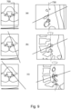
- FIG 8 illustrates an example of sectional views obtained when rotating a plane passing through two entry points, according to the mechanism illustrated on the figure 7 .
- the views located on the left part are sectional views along the plane 705 passing through the entry points 715 and 720 while the views located on the right part are sectional views along the plane 710, including the right 730 ( perpendicular to plane 705 and passing through entry point 715).
- the sets of views referenced (a), (b) and (c) correspond to different values of the angle ⁇ .
- FIG. 9 illustrates an example of sectional views obtained when rotating a plane perpendicular to a plane passing through two entry points, according to the mechanism illustrated in the Figure 7 .
- the views located on the left part are sectional views according to plan 705 passing through the entry points 715 and 720 while the views located on the right part are sectional views according to plan 710, including the straight 730 (perpendicular to plane 705 and passing through entry point 715).
- the sets of views referenced (a), (b) and (c) correspond to different values of the angle ⁇ .
- the values of the angles ⁇ and ⁇ can be modified by a user to allow him, from the sectional views, to determine the insertion axis which seems optimal to him.
- the values of the angles ⁇ and ⁇ can be modified automatically, according to predetermined increments. For each increment, an analysis of the sectional views is carried out to determine whether the insertion axis defined by the angles ⁇ and ⁇ satisfies predetermined criteria. If these criteria are satisfied, the algorithm ends or memorizes the identified values to later compare the different insertion axes satisfying the predetermined criteria and select the insertion axis presenting optimal criteria.
- assistance is provided to the user to allow him to modify the angles ⁇ and ⁇ while indicating to him whether the current values of these angles satisfy predetermined criteria.
- the insertion axis can be colored in green if the insertion axis meets the predetermined criteria and in red if the latter are not.
- these colors can be more or less intense depending, for example, on a quantification of risk associated with a position of the insertion axis.
- FIG. 10 represents an example of an information processing device making it possible to implement the method according to embodiments of the invention, in particular to execute all or some of the steps described with reference to the figures 2 , 3 and 4 .
- the device 1000 comprises a memory 1005 for storing instructions allowing the implementation of the method, the measurement data received and temporary data for carrying out different steps of the method as described above.
- SOCs and systems on a chip are embedded systems that integrate all the components of an electronic system into a single chip.
- An ASIC is a specialized electronic circuit that brings together tailor-made functionalities for a given application. ASICs are usually configured when they are manufactured.
- FPGA type programmable logic circuits are electronic circuits that can be reconfigured by a user.
- the device 1000 here comprises an input interface 1015 for receiving measurement data, for example CT data allowing the construction of a 3D model, and an output interface 1020. Finally, it may include, to allow interaction easy with a user, a screen 1025, a keyboard 1030 and a mouse 1035, preferably provided with a wheel.
- the keyboard is optional, particularly in the context of a computer in the form of a touchscreen tablet, for example.
- the device 1000 may be a computer, a computer network, an electronic component or another device comprising a processor operationally coupled to a memory, as well as, depending on the chosen embodiment, a data storage unit and other associated hardware elements such as a network interface and a media drive for reading from and writing to removable storage media (not shown in the figure).
- the removable storage medium may be, for example, a compact disc (CD), a video/digital versatile disc (DVD), a flash disk, a USB key, etc.
- the memory, the data storage unit or the removable storage medium contains instructions which, when executed by the circuit 1010, cause this circuit 1010 to perform or control the interface portions of input 1015, output interface 1020, data storage in memory 1005 and/or data processing.
Landscapes
- Health & Medical Sciences (AREA)
- Engineering & Computer Science (AREA)
- Life Sciences & Earth Sciences (AREA)
- Surgery (AREA)
- Orthopedic Medicine & Surgery (AREA)
- Physics & Mathematics (AREA)
- Animal Behavior & Ethology (AREA)
- Heart & Thoracic Surgery (AREA)
- Veterinary Medicine (AREA)
- Public Health (AREA)
- Nuclear Medicine, Radiotherapy & Molecular Imaging (AREA)
- General Health & Medical Sciences (AREA)
- Molecular Biology (AREA)
- Medical Informatics (AREA)
- Biomedical Technology (AREA)
- Software Systems (AREA)
- Theoretical Computer Science (AREA)
- General Physics & Mathematics (AREA)
- Neurology (AREA)
- Computer Graphics (AREA)
- Robotics (AREA)
- General Engineering & Computer Science (AREA)
- Computer Hardware Design (AREA)
- Geometry (AREA)
- Processing Or Creating Images (AREA)
- Surgical Instruments (AREA)
- Apparatus For Radiation Diagnosis (AREA)
Claims (13)
- Verfahren zur Unterstützung eines invasiven Eingriffs an einem menschlichen oder tierischen Organ, wobei der Eingriff das Einführen mindestens eines Elements in das Organ umfasst, wobei das Verfahren Folgendes umfasst:a. Erhalten eines dreidimensionalen Modells von mindestens einem Teil des Organs;b. Bestimmen, anhand des erhaltenen dreidimensionalen Modells, mindestens eines Eintrittspunkts des mindestens einen Elements;c. Bestimmen einer Einführachse für das mindestens eine Element in das Organ gemäß dem dreidimensionalen Modell, des mindestens einen bestimmten Eintrittspunkts und einer Vielzahl verschiedener Achsen, die durch den mindestens einen Eintrittspunkt verlaufen, wobei die Vielzahl von Achsen durch den Schnittpunkt einer ersten und einer zweiten Ebene definiert ist, wobei die erste und die zweite Ebene den mindestens einen Eintrittspunkt umfassen,d. Anzeigen einer Querschnittsansicht des dreidimensionalen Modells in der ersten Ebene, wobei die erste Ebene einen ersten Winkel im Verhältnis zu einem ersten Bezugspunkt bildet, der mit dem dreidimensionalen Modell verknüpft ist,dadurch gekennzeichnet, dass das Verfahren Folgendes umfasst:
e. Modifizieren des Werts des ersten Winkels, wobei die Anzeige einer Querschnittsansicht in der ersten Ebene an das Modifizieren des ersten Winkels angepasst wird. - Verfahren nach Anspruch 1, das ferner das Erstellen des dreidimensionalen Modells umfasst.
- Verfahren nach Anspruch 1 oder Anspruch 2, das das Anzeigen einer Darstellung mindestens eines Teils des dreidimensionalen Modells umfasst, wobei das Anzeigen mindestens eines Teils des dreidimensionalen Modells das Anzeigen und/oder das Bestimmen mindestens eines Eintrittspunkts ermöglicht.
- Verfahren nach einem der Ansprüche 1 bis 3, wobei mindestens zwei Eintrittspunkte bestimmt werden, wobei die erste Ebene eine gerade Linie umfasst, die durch die mindestens zwei Eintrittspunkte verläuft.
- Verfahren nach Anspruch 4, wobei die zweite Ebene eine gerade Linie senkrecht zur ersten Ebene umfasst.
- Verfahren nach einem der Ansprüche 1 bis 5, das ferner das Anzeigen einer Querschnittsansicht des dreidimensionalen Modells in der zweiten Ebene umfasst, wobei die zweite Ebene einen zweiten Winkel im Verhältnis zu einem zweiten Bezugspunkt bildet, der mit dem dreidimensionalen Modell verknüpft ist.
- Verfahren nach Anspruch 6, wobei der Wert des zweiten Winkels geändert wird, wobei das Anzeigen einer Querschnittsansicht in der zweiten Ebene an das Modifizieren des zweiten Winkels angepasst wird.
- Verfahren nach einem der Ansprüche 1 bis 7, das das Verschieben mindestens eines auf dem dreidimensionalen Modell definierten Eintrittspunkts umfasst.
- Verfahren nach einem der Ansprüche 1 bis 8, das ein Messen eines Durchmessers und/oder einer Länge eines einzusetzenden Elements gemäß einem bestimmten Eintrittspunkt, einer bestimmten Einführungsachse und dem dreidimensionalen Modell umfasst.
- Verfahren nach einem der Ansprüche 1 bis 9, wobei das Organ ein Wirbel ist und das einzuführende Element eine Pedikelschraube ist.
- Computerprogrammprodukt, das Anweisungen zum Durchführen jeder der Schritte des Verfahrens nach einem der Ansprüche 1 bis 10 umfasst, wenn dieses Programm von einem Prozessor ausgeführt wird.
- Computerlesbares, nichtflüchtiges Aufzeichnungsmedium, auf dem ein Programm zum Durchführen jedes der Schritte des Verfahrens nach einem der Ansprüche 1 bis 10 aufgezeichnet ist, wenn dieses Programm von einem Prozessor ausgeführt wird.
- Vorrichtung, die eine Recheneinheit umfasst, die dazu konfiguriert ist, jeden der Schritte des Verfahrens nach einem der Ansprüche 1 bis 10 auszuführen.
Applications Claiming Priority (2)
| Application Number | Priority Date | Filing Date | Title |
|---|---|---|---|
| FR2002648A FR3108419A1 (fr) | 2020-03-18 | 2020-03-18 | Procédé et dispositif d’aide à une intervention invasive sur un organe humain ou animal |
| PCT/EP2021/056898 WO2021185940A1 (fr) | 2020-03-18 | 2021-03-18 | Procédé et dispositif d'aide à une intervention invasive sur un organe humain ou animal. |
Publications (3)
| Publication Number | Publication Date |
|---|---|
| EP4120946A1 EP4120946A1 (de) | 2023-01-25 |
| EP4120946C0 EP4120946C0 (de) | 2024-05-08 |
| EP4120946B1 true EP4120946B1 (de) | 2024-05-08 |
Family
ID=71575446
Family Applications (1)
| Application Number | Title | Priority Date | Filing Date |
|---|---|---|---|
| EP21711598.9A Active EP4120946B1 (de) | 2020-03-18 | 2021-03-18 | Verfahren und vorrichtung zur unterstützung eines invasiven eingriffs an einem menschlichen oder tierischen organ |
Country Status (5)
| Country | Link |
|---|---|
| US (1) | US20230138599A1 (de) |
| EP (1) | EP4120946B1 (de) |
| ES (1) | ES2994695T3 (de) |
| FR (1) | FR3108419A1 (de) |
| WO (1) | WO2021185940A1 (de) |
Families Citing this family (2)
| Publication number | Priority date | Publication date | Assignee | Title |
|---|---|---|---|---|
| WO2021034706A1 (en) | 2019-08-16 | 2021-02-25 | Tornier, Inc. | Pre-operative planning of surgical revision procedures for orthopedic joints |
| AU2021224529B2 (en) | 2020-02-18 | 2024-02-15 | Howmedica Osteonics Corp. | Computer-implemented surgical planning based on bone loss during orthopedic revision surgery |
Family Cites Families (12)
| Publication number | Priority date | Publication date | Assignee | Title |
|---|---|---|---|---|
| EP2029059A2 (de) * | 2006-05-25 | 2009-03-04 | Spinemedica Corporation | Patientenspezifische wirbelsäulenimplantate sowie entsprechende systeme und verfahren |
| US8335553B2 (en) * | 2006-09-25 | 2012-12-18 | Mazor Robotics Ltd. | CT-free spinal surgical imaging system |
| EP2475300A1 (de) * | 2009-09-08 | 2012-07-18 | BrainLAB AG | Bestimmung einer fläche eines anatomischen körperteils |
| CA2797302C (en) * | 2010-04-28 | 2019-01-15 | Ryerson University | System and methods for intraoperative guidance feedback |
| US9839438B2 (en) * | 2013-03-11 | 2017-12-12 | Biomet Manufacturing, Llc | Patient-specific glenoid guide with a reusable guide holder |
| US10034675B2 (en) * | 2013-03-13 | 2018-07-31 | Think Surgical, Inc. | Systems and methods for pre-operative planning and precise bone tunnel placement for ligament reconstruction |
| SE542045C2 (en) * | 2016-05-15 | 2020-02-18 | Ortoma Ab | Calibration object, system, and method calibrating location of instrument in a navigation system |
| CN110769770A (zh) * | 2017-03-21 | 2020-02-07 | 思想外科有限公司 | 两自由度系统和用于脊部应用的方法 |
| US10561466B2 (en) * | 2017-08-10 | 2020-02-18 | Sectra Ab | Automated planning systems for pedicle screw placement and related methods |
| EP3821403A4 (de) * | 2018-07-09 | 2022-03-23 | Ottawa Hospital Research Institute | Virtuelles oder durch erweiterte realität unterstütztes 3d-visualisierungs- und -markierungssystem |
| EP3883491A4 (de) * | 2018-11-22 | 2022-08-24 | Vuze Medical Ltd. | Vorrichtung und verfahren zur verwendung mit bildgeführten skeletteingriffen |
| EP3847990B1 (de) * | 2020-01-13 | 2022-04-06 | Stryker European Operations Limited | Technik zur steuerung der anzeige einer navigationsansicht, die einen sich augenblicklich ändernden empfohlenen einstiegspunkt anzeigt |
-
2020
- 2020-03-18 FR FR2002648A patent/FR3108419A1/fr active Pending
-
2021
- 2021-03-18 US US17/912,434 patent/US20230138599A1/en not_active Abandoned
- 2021-03-18 ES ES21711598T patent/ES2994695T3/es active Active
- 2021-03-18 WO PCT/EP2021/056898 patent/WO2021185940A1/fr not_active Ceased
- 2021-03-18 EP EP21711598.9A patent/EP4120946B1/de active Active
Also Published As
| Publication number | Publication date |
|---|---|
| US20230138599A1 (en) | 2023-05-04 |
| EP4120946C0 (de) | 2024-05-08 |
| EP4120946A1 (de) | 2023-01-25 |
| WO2021185940A1 (fr) | 2021-09-23 |
| ES2994695T3 (en) | 2025-01-30 |
| FR3108419A1 (fr) | 2021-09-24 |
Similar Documents
| Publication | Publication Date | Title |
|---|---|---|
| EP1579354B1 (de) | Verfahren zur biomechanischen simulation einer gruppe von gelenken | |
| EP3913578B1 (de) | Verfahren und vorrichtung zur registrierung von bildern, die anatomische strukturen enthalten | |
| Glombitza et al. | Virtual planning of liver resections: image processing, visualization and volumetric evaluation | |
| US8131033B2 (en) | Sensitivity lens for assessing uncertainty in image visualizations of data sets, related methods and computer products | |
| WO1991004711A1 (fr) | Systeme interactif d'intervention locale a l'interieur d'une structure non homogene | |
| EP2089827A1 (de) | System und verfahren zur bildannotation auf der basis von objekt-ebenenschnitten | |
| EP2102812A1 (de) | Analyse von läsionen in einem medizinischen digitalbild | |
| JP2012510317A (ja) | 脊椎のラベル付けの伝搬のためのシステムおよび方法 | |
| US11229377B2 (en) | System and method for next-generation MRI spine evaluation | |
| Cevidanes et al. | Incorporating 3-dimensional models in online articles | |
| FR2862791A1 (fr) | Procede de segmentation d'une structure et systeme d'imagerie associe | |
| EP4120946B1 (de) | Verfahren und vorrichtung zur unterstützung eines invasiven eingriffs an einem menschlichen oder tierischen organ | |
| WO2004095378A1 (en) | Combined 3d and 2d views | |
| CN101005803A (zh) | 灵活融合3dra-ct的方法 | |
| CN1804866A (zh) | 在对象的平面图像上对齐图形对象的方法 | |
| JP5586953B2 (ja) | 解剖学的形状情報を用いた医学画像データベースへのアクセス | |
| WO2024126656A1 (fr) | Dispositif d'assistance à la planification d'une intervention mini-invasive | |
| EP4558075A1 (de) | Vorrichtung zur unterstützung der planung eines minimalinvasiven eingriffs an einem knochen | |
| FR3136645A1 (fr) | Dispositif de génération d’une séquence d'images représentant une suite continue d’éléments osseux en mouvement | |
| Pijpker et al. | A semi-automatic seed point-based method for separation of individual vertebrae in 3D surface meshes: a proof of principle study | |
| FR3145860A1 (fr) | Procédé de génération d’un modèle d’un ensemble osseux | |
| Luis et al. | 3D printing of medical models from CT-MRI images: A practical step-by-step guide | |
| CN1745706A (zh) | 确定标志性冠状和矢状平面的方法 | |
| Tiribilli | Study of a bone segmentation and 3D modeling workflow for diagnosis and planning | |
| CN120782707A (zh) | 一种椎间盘定位方法及装置 |
Legal Events
| Date | Code | Title | Description |
|---|---|---|---|
| STAA | Information on the status of an ep patent application or granted ep patent |
Free format text: STATUS: UNKNOWN |
|
| STAA | Information on the status of an ep patent application or granted ep patent |
Free format text: STATUS: THE INTERNATIONAL PUBLICATION HAS BEEN MADE |
|
| PUAI | Public reference made under article 153(3) epc to a published international application that has entered the european phase |
Free format text: ORIGINAL CODE: 0009012 |
|
| STAA | Information on the status of an ep patent application or granted ep patent |
Free format text: STATUS: REQUEST FOR EXAMINATION WAS MADE |
|
| 17P | Request for examination filed |
Effective date: 20220929 |
|
| AK | Designated contracting states |
Kind code of ref document: A1 Designated state(s): AL AT BE BG CH CY CZ DE DK EE ES FI FR GB GR HR HU IE IS IT LI LT LU LV MC MK MT NL NO PL PT RO RS SE SI SK SM TR |
|
| DAV | Request for validation of the european patent (deleted) | ||
| DAX | Request for extension of the european patent (deleted) | ||
| GRAP | Despatch of communication of intention to grant a patent |
Free format text: ORIGINAL CODE: EPIDOSNIGR1 |
|
| STAA | Information on the status of an ep patent application or granted ep patent |
Free format text: STATUS: GRANT OF PATENT IS INTENDED |
|
| INTG | Intention to grant announced |
Effective date: 20231023 |
|
| GRAS | Grant fee paid |
Free format text: ORIGINAL CODE: EPIDOSNIGR3 |
|
| GRAA | (expected) grant |
Free format text: ORIGINAL CODE: 0009210 |
|
| STAA | Information on the status of an ep patent application or granted ep patent |
Free format text: STATUS: THE PATENT HAS BEEN GRANTED |
|
| AK | Designated contracting states |
Kind code of ref document: B1 Designated state(s): AL AT BE BG CH CY CZ DE DK EE ES FI FR GB GR HR HU IE IS IT LI LT LU LV MC MK MT NL NO PL PT RO RS SE SI SK SM TR |
|
| REG | Reference to a national code |
Ref country code: GB Ref legal event code: FG4D Free format text: NOT ENGLISH |
|
| REG | Reference to a national code |
Ref country code: CH Ref legal event code: EP |
|
| REG | Reference to a national code |
Ref country code: DE Ref legal event code: R096 Ref document number: 602021013042 Country of ref document: DE |
|
| REG | Reference to a national code |
Ref country code: IE Ref legal event code: FG4D Free format text: LANGUAGE OF EP DOCUMENT: FRENCH |
|
| U01 | Request for unitary effect filed |
Effective date: 20240523 |
|
| U07 | Unitary effect registered |
Designated state(s): AT BE BG DE DK EE FI FR IT LT LU LV MT NL PT SE SI Effective date: 20240606 |
|
| PG25 | Lapsed in a contracting state [announced via postgrant information from national office to epo] |
Ref country code: IS Free format text: LAPSE BECAUSE OF FAILURE TO SUBMIT A TRANSLATION OF THE DESCRIPTION OR TO PAY THE FEE WITHIN THE PRESCRIBED TIME-LIMIT Effective date: 20240908 |
|
| PG25 | Lapsed in a contracting state [announced via postgrant information from national office to epo] |
Ref country code: HR Free format text: LAPSE BECAUSE OF FAILURE TO SUBMIT A TRANSLATION OF THE DESCRIPTION OR TO PAY THE FEE WITHIN THE PRESCRIBED TIME-LIMIT Effective date: 20240508 |
|
| PG25 | Lapsed in a contracting state [announced via postgrant information from national office to epo] |
Ref country code: GR Free format text: LAPSE BECAUSE OF FAILURE TO SUBMIT A TRANSLATION OF THE DESCRIPTION OR TO PAY THE FEE WITHIN THE PRESCRIBED TIME-LIMIT Effective date: 20240809 |
|
| PG25 | Lapsed in a contracting state [announced via postgrant information from national office to epo] |
Ref country code: PL Free format text: LAPSE BECAUSE OF FAILURE TO SUBMIT A TRANSLATION OF THE DESCRIPTION OR TO PAY THE FEE WITHIN THE PRESCRIBED TIME-LIMIT Effective date: 20240508 |
|
| PG25 | Lapsed in a contracting state [announced via postgrant information from national office to epo] |
Ref country code: PL Free format text: LAPSE BECAUSE OF FAILURE TO SUBMIT A TRANSLATION OF THE DESCRIPTION OR TO PAY THE FEE WITHIN THE PRESCRIBED TIME-LIMIT Effective date: 20240508 Ref country code: NO Free format text: LAPSE BECAUSE OF FAILURE TO SUBMIT A TRANSLATION OF THE DESCRIPTION OR TO PAY THE FEE WITHIN THE PRESCRIBED TIME-LIMIT Effective date: 20240808 Ref country code: IS Free format text: LAPSE BECAUSE OF FAILURE TO SUBMIT A TRANSLATION OF THE DESCRIPTION OR TO PAY THE FEE WITHIN THE PRESCRIBED TIME-LIMIT Effective date: 20240908 Ref country code: HR Free format text: LAPSE BECAUSE OF FAILURE TO SUBMIT A TRANSLATION OF THE DESCRIPTION OR TO PAY THE FEE WITHIN THE PRESCRIBED TIME-LIMIT Effective date: 20240508 Ref country code: GR Free format text: LAPSE BECAUSE OF FAILURE TO SUBMIT A TRANSLATION OF THE DESCRIPTION OR TO PAY THE FEE WITHIN THE PRESCRIBED TIME-LIMIT Effective date: 20240809 Ref country code: RS Free format text: LAPSE BECAUSE OF FAILURE TO SUBMIT A TRANSLATION OF THE DESCRIPTION OR TO PAY THE FEE WITHIN THE PRESCRIBED TIME-LIMIT Effective date: 20240808 |
|
| PG25 | Lapsed in a contracting state [announced via postgrant information from national office to epo] |
Ref country code: CZ Free format text: LAPSE BECAUSE OF FAILURE TO SUBMIT A TRANSLATION OF THE DESCRIPTION OR TO PAY THE FEE WITHIN THE PRESCRIBED TIME-LIMIT Effective date: 20240508 |
|
| PG25 | Lapsed in a contracting state [announced via postgrant information from national office to epo] |
Ref country code: SK Free format text: LAPSE BECAUSE OF FAILURE TO SUBMIT A TRANSLATION OF THE DESCRIPTION OR TO PAY THE FEE WITHIN THE PRESCRIBED TIME-LIMIT Effective date: 20240508 Ref country code: RO Free format text: LAPSE BECAUSE OF FAILURE TO SUBMIT A TRANSLATION OF THE DESCRIPTION OR TO PAY THE FEE WITHIN THE PRESCRIBED TIME-LIMIT Effective date: 20240508 |
|
| PG25 | Lapsed in a contracting state [announced via postgrant information from national office to epo] |
Ref country code: SM Free format text: LAPSE BECAUSE OF FAILURE TO SUBMIT A TRANSLATION OF THE DESCRIPTION OR TO PAY THE FEE WITHIN THE PRESCRIBED TIME-LIMIT Effective date: 20240508 |
|
| REG | Reference to a national code |
Ref country code: ES Ref legal event code: FG2A Ref document number: 2994695 Country of ref document: ES Kind code of ref document: T3 Effective date: 20250130 |
|
| PG25 | Lapsed in a contracting state [announced via postgrant information from national office to epo] |
Ref country code: SM Free format text: LAPSE BECAUSE OF FAILURE TO SUBMIT A TRANSLATION OF THE DESCRIPTION OR TO PAY THE FEE WITHIN THE PRESCRIBED TIME-LIMIT Effective date: 20240508 Ref country code: SK Free format text: LAPSE BECAUSE OF FAILURE TO SUBMIT A TRANSLATION OF THE DESCRIPTION OR TO PAY THE FEE WITHIN THE PRESCRIBED TIME-LIMIT Effective date: 20240508 Ref country code: RO Free format text: LAPSE BECAUSE OF FAILURE TO SUBMIT A TRANSLATION OF THE DESCRIPTION OR TO PAY THE FEE WITHIN THE PRESCRIBED TIME-LIMIT Effective date: 20240508 Ref country code: CZ Free format text: LAPSE BECAUSE OF FAILURE TO SUBMIT A TRANSLATION OF THE DESCRIPTION OR TO PAY THE FEE WITHIN THE PRESCRIBED TIME-LIMIT Effective date: 20240508 |
|
| REG | Reference to a national code |
Ref country code: DE Ref legal event code: R097 Ref document number: 602021013042 Country of ref document: DE |
|
| PLBE | No opposition filed within time limit |
Free format text: ORIGINAL CODE: 0009261 |
|
| STAA | Information on the status of an ep patent application or granted ep patent |
Free format text: STATUS: NO OPPOSITION FILED WITHIN TIME LIMIT |
|
| 26N | No opposition filed |
Effective date: 20250211 |
|
| U20 | Renewal fee for the european patent with unitary effect paid |
Year of fee payment: 5 Effective date: 20250325 |
|
| PGFP | Annual fee paid to national office [announced via postgrant information from national office to epo] |
Ref country code: ES Payment date: 20250411 Year of fee payment: 5 |
|
| PGFP | Annual fee paid to national office [announced via postgrant information from national office to epo] |
Ref country code: CH Payment date: 20250425 Year of fee payment: 5 |
|
| PG25 | Lapsed in a contracting state [announced via postgrant information from national office to epo] |
Ref country code: MC Free format text: LAPSE BECAUSE OF FAILURE TO SUBMIT A TRANSLATION OF THE DESCRIPTION OR TO PAY THE FEE WITHIN THE PRESCRIBED TIME-LIMIT Effective date: 20240508 |
|
| PG25 | Lapsed in a contracting state [announced via postgrant information from national office to epo] |
Ref country code: IE Free format text: LAPSE BECAUSE OF NON-PAYMENT OF DUE FEES Effective date: 20250318 |
|
| PGFP | Annual fee paid to national office [announced via postgrant information from national office to epo] |
Ref country code: GB Payment date: 20260327 Year of fee payment: 6 |