EP1579354B1 - Verfahren zur biomechanischen simulation einer gruppe von gelenken - Google Patents
Verfahren zur biomechanischen simulation einer gruppe von gelenken Download PDFInfo
- Publication number
- EP1579354B1 EP1579354B1 EP03814510.8A EP03814510A EP1579354B1 EP 1579354 B1 EP1579354 B1 EP 1579354B1 EP 03814510 A EP03814510 A EP 03814510A EP 1579354 B1 EP1579354 B1 EP 1579354B1
- Authority
- EP
- European Patent Office
- Prior art keywords
- joints
- patient
- model
- digital model
- osseous
- Prior art date
- Legal status (The legal status is an assumption and is not a legal conclusion. Google has not performed a legal analysis and makes no representation as to the accuracy of the status listed.)
- Expired - Lifetime
Links
- 238000000034 method Methods 0.000 title claims description 37
- 239000007943 implant Substances 0.000 claims description 13
- 238000009826 distribution Methods 0.000 claims description 12
- 230000003993 interaction Effects 0.000 claims description 12
- 230000009471 action Effects 0.000 claims description 11
- 210000000988 bone and bone Anatomy 0.000 claims description 11
- 238000002513 implantation Methods 0.000 claims description 6
- 230000000694 effects Effects 0.000 claims description 4
- 238000010276 construction Methods 0.000 claims description 3
- 230000006870 function Effects 0.000 claims description 3
- 210000003041 ligament Anatomy 0.000 claims description 2
- 238000012986 modification Methods 0.000 claims description 2
- 230000004048 modification Effects 0.000 claims description 2
- 230000005477 standard model Effects 0.000 claims description 2
- 230000003068 static effect Effects 0.000 claims description 2
- 238000004088 simulation Methods 0.000 description 19
- 208000031968 Cadaver Diseases 0.000 description 10
- 230000037230 mobility Effects 0.000 description 10
- 238000013459 approach Methods 0.000 description 9
- 230000006399 behavior Effects 0.000 description 9
- 238000004364 calculation method Methods 0.000 description 9
- 238000004458 analytical method Methods 0.000 description 7
- 238000011282 treatment Methods 0.000 description 5
- 210000001835 viscera Anatomy 0.000 description 5
- 241000220257 Matthiola Species 0.000 description 4
- 235000011378 Matthiola incana Nutrition 0.000 description 4
- 238000001727 in vivo Methods 0.000 description 4
- 238000002601 radiography Methods 0.000 description 4
- 235000021547 stock Nutrition 0.000 description 4
- 230000005484 gravity Effects 0.000 description 3
- 210000004197 pelvis Anatomy 0.000 description 3
- 230000036544 posture Effects 0.000 description 3
- 238000012360 testing method Methods 0.000 description 3
- 241000700608 Sagitta Species 0.000 description 2
- 238000004422 calculation algorithm Methods 0.000 description 2
- 238000012937 correction Methods 0.000 description 2
- 238000011156 evaluation Methods 0.000 description 2
- 210000003205 muscle Anatomy 0.000 description 2
- 230000003387 muscular Effects 0.000 description 2
- 230000007170 pathology Effects 0.000 description 2
- 230000002980 postoperative effect Effects 0.000 description 2
- 210000004872 soft tissue Anatomy 0.000 description 2
- 239000007787 solid Substances 0.000 description 2
- 230000006641 stabilisation Effects 0.000 description 2
- 238000011105 stabilization Methods 0.000 description 2
- 238000001356 surgical procedure Methods 0.000 description 2
- 206010013786 Dry skin Diseases 0.000 description 1
- 208000007623 Lordosis Diseases 0.000 description 1
- 208000000875 Spinal Curvatures Diseases 0.000 description 1
- 241001080024 Telles Species 0.000 description 1
- 230000006978 adaptation Effects 0.000 description 1
- 210000003484 anatomy Anatomy 0.000 description 1
- 230000003190 augmentative effect Effects 0.000 description 1
- 238000005452 bending Methods 0.000 description 1
- 210000000748 cardiovascular system Anatomy 0.000 description 1
- 230000008859 change Effects 0.000 description 1
- 230000008878 coupling Effects 0.000 description 1
- 238000010168 coupling process Methods 0.000 description 1
- 238000005859 coupling reaction Methods 0.000 description 1
- 238000005520 cutting process Methods 0.000 description 1
- 238000007405 data analysis Methods 0.000 description 1
- 230000007423 decrease Effects 0.000 description 1
- 238000002059 diagnostic imaging Methods 0.000 description 1
- 238000006073 displacement reaction Methods 0.000 description 1
- 230000004064 dysfunction Effects 0.000 description 1
- 239000012636 effector Substances 0.000 description 1
- 239000004744 fabric Substances 0.000 description 1
- 230000036541 health Effects 0.000 description 1
- 230000002706 hydrostatic effect Effects 0.000 description 1
- 238000000338 in vitro Methods 0.000 description 1
- 230000002452 interceptive effect Effects 0.000 description 1
- 210000003127 knee Anatomy 0.000 description 1
- WABPQHHGFIMREM-UHFFFAOYSA-N lead(0) Chemical compound [Pb] WABPQHHGFIMREM-UHFFFAOYSA-N 0.000 description 1
- 238000012417 linear regression Methods 0.000 description 1
- 238000013507 mapping Methods 0.000 description 1
- 239000003550 marker Substances 0.000 description 1
- 239000011159 matrix material Substances 0.000 description 1
- 230000007246 mechanism Effects 0.000 description 1
- 239000003607 modifier Substances 0.000 description 1
- 230000003562 morphometric effect Effects 0.000 description 1
- 238000013425 morphometry Methods 0.000 description 1
- 238000005457 optimization Methods 0.000 description 1
- 230000008569 process Effects 0.000 description 1
- 238000012545 processing Methods 0.000 description 1
- 238000011160 research Methods 0.000 description 1
- 206010039722 scoliosis Diseases 0.000 description 1
- 238000004513 sizing Methods 0.000 description 1
- 210000001519 tissue Anatomy 0.000 description 1
- 238000012549 training Methods 0.000 description 1
- 230000009466 transformation Effects 0.000 description 1
- 230000007704 transition Effects 0.000 description 1
- 210000000689 upper leg Anatomy 0.000 description 1
- 210000000707 wrist Anatomy 0.000 description 1
Images


Classifications
-
- G—PHYSICS
- G16—INFORMATION AND COMMUNICATION TECHNOLOGY [ICT] SPECIALLY ADAPTED FOR SPECIFIC APPLICATION FIELDS
- G16H—HEALTHCARE INFORMATICS, i.e. INFORMATION AND COMMUNICATION TECHNOLOGY [ICT] SPECIALLY ADAPTED FOR THE HANDLING OR PROCESSING OF MEDICAL OR HEALTHCARE DATA
- G16H50/00—ICT specially adapted for medical diagnosis, medical simulation or medical data mining; ICT specially adapted for detecting, monitoring or modelling epidemics or pandemics
- G16H50/50—ICT specially adapted for medical diagnosis, medical simulation or medical data mining; ICT specially adapted for detecting, monitoring or modelling epidemics or pandemics for simulation or modelling of medical disorders
-
- G—PHYSICS
- G16—INFORMATION AND COMMUNICATION TECHNOLOGY [ICT] SPECIALLY ADAPTED FOR SPECIFIC APPLICATION FIELDS
- G16H—HEALTHCARE INFORMATICS, i.e. INFORMATION AND COMMUNICATION TECHNOLOGY [ICT] SPECIALLY ADAPTED FOR THE HANDLING OR PROCESSING OF MEDICAL OR HEALTHCARE DATA
- G16H30/00—ICT specially adapted for the handling or processing of medical images
- G16H30/20—ICT specially adapted for the handling or processing of medical images for handling medical images, e.g. DICOM, HL7 or PACS
Definitions
- the present invention relates to the field of biomedical simulation software.
- the present invention relates more particularly to a method of biomechanical simulation of a set of bone joints of a patient, including the spine. This method makes it possible to calculate, estimate and visualize the consequences of a surgical operation on a joint.
- the system has been developed for spine operations and in particular spinal stabilization techniques. In general, the system makes it possible to inform the surgeon about the state of equilibrium and the distribution of the forces in the patient's column before and after the simulation.
- the prior art already knows, by the US patent application US 5,995,738 , a device and a method for facilitating the implantation of artificial components into the joints.
- the invention describes devices and methods for determining an implant position for at least one artificial component in a joint and facilitating its implantation.
- the invention includes creating a model of the patient's joint and creating a model of the component to be implanted.
- the created models are used to simulate the movement of the patient's joint according to the position of the component.
- This document of the prior art therefore proposes a means of physical simulation and not virtual to analyze the movements of a joint and an implant.
- the invention relates to an apparatus for facilitating the implantation of an artificial component into a joint.
- the apparatus includes a geometric predictor and a biomechanical simulator of preoperative movement, i.e., a series of simulations is performed on the implant and the joint prior to performing the operation.
- the invention describes a method for analyzing and displaying the movements of a human being.
- the body of the subject is divided into a plurality of segments interconnected by joints. Once the body is modeled in this way, it is possible to simulate and analyze the movement of the subject.
- At least one command such as a shape command or a resolution plane command is defined for the articulated chain, and this command is used as a constraint taken up by the animation engine for the animation of the animation.
- the chain with inverse kinematics.
- Each command comprises at least two keys, each key comprising a pair consisting of an effector direction vector and an associated constraint.
- shape control keys the associated constraints include a list of preferred orientations of the members of the body.
- the associated constraints include a preferential orientation of the resolution plane.
- the present invention intends to overcome the disadvantages of the prior art by making it possible to simulate a local or global correction operation of vertebral column curvatures or vertebral implant placement from radiographic images, of series of acquisitions of characteristics. measured in vivo on the patient and an implant database.
- the present invention further allows the state of the column to be simulated immediately after the surgical operation.
- the present invention does not apply only to the spine. It also applies to other bone joints such as the knee.
- the invention consists of a computer-assisted surgical system, allowing the surgeon to simulate, preoperatively, the effects on the patient of the corrective surgery that he plans to implement.
- This system allows him to simulate several operating strategies, and offers the surgeon a tool to help choose the operating strategy that offers the best compromise between stabilization and mobility.
- the numerical model is defined by parameters of geometrical positions of the rigid bodies and by stiffness parameters of the joints connecting the rigid bodies.
- the step of representing the result of a constraint consists in recalculating the personalized model [in equilibrium position] resulting from a set of constraints [for example implantation of a prosthesis or an implant] comprising at least a static stress exerted on at least two rigid bodies, and imposing a relative positioning with a mobility or a stiffness different from that corresponding to the law of behavior.
- the step of recording the numerical model of the set of standard joints consists of defining an alternation of rigid bodies and articulations, and defining for each of the pairs of bodies a set of numerical parameters characterizing the mobility or global stiffness resulting from the action of all the intermediate elements [for example intervertebral discs] and connecting elements [for example ligaments] having an effect on the interaction parameters [stiffness] between the two bodies.
- the personalization step consists in acquiring at least one image of the set of articulations of a given patient, in extracting from said image the information necessary for constructing a real model. by recognizing the position of the visible joints in said image, and modifying the standard model according to said real model.
- the invention differs from known surgical guidance products used to assist the surgeon during his operation. Indeed, the invention consists in particular in modeling the vertebral column of the individual who will be operated, to simulate the implantation of the implant or prosthesis and calculate the equilibrium position of the individual once the implant or prosthesis is placed.
- the data processing being software
- the invention also relates to the software architecture implemented for the realization of the functional architecture.
- the software structure includes several database servers: a user database, a vertebra database, a patient database and an implant database.
- the data contained in these databases are interrogated and updated by different users in order to build the 3D model of the patient's column and then to simulate the consequences of implant placement.
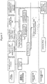
- the system according to the invention is a simulator of the biomechanical and kinematic consequences of the surgical act of treatment of spinal pathologies on the morphology of the patient.
- the Figure 2 represents the general architecture of the simulator.
- the simulator is a tool to help analyze the feasibility of the gesture. It allows to simulate the preoperative equilibrium, the corresponding inter-segmental efforts taking into account the effect of muscular and ligamentary rigidities, to apprehend the evolution of this equilibrium and of these postoperative efforts according to the curvatures introduced by the surgeon. during the operation. The surgeon will have to indicate as input the desired deformation of the instrumented zone. For this, a so-called "global" approach will be used.
- the power supply of the system can be manual (a user will supply the image files to the system) or automatic, the images are stored directly by the radiology devices and retrieved via an intranet / internet network.
- the specific points detected by the digitization will make it possible to calculate the 3D coordinates of the vertebrae (geometrical data).
- the geometric data from the digital images will allow to build a model of the patient's column in three dimensions.
- This model results the adaptation of a standard 3D model, predefined in the system, to the geometric characteristics of the patient.
- the user must be able to visualize the 3D model of the spine according to the frontal, sagittal and apical planes; moreover, it must be able to compare it to the radiographs used for its construction.
- the mechanical characteristics of the patient allow to customize the model.
- a standard geometric model of the vertebral column is enriched by the personal mechanical data of the patient concerned.
- the biomechanical characteristics of the patient's column are calculated from the patient's radiographs (before the first simulation), or from the model resulting from a simulation. Some parameters may be pre-calculated (sacral slope, angle of incidence, sagittal location, spinal curvature) on X-rays.
- the user must have the possibility to choose segments of column on which he imposes displacements.
- the user will be able to enter the values of certain clinical parameters that he wishes to simulate for a given segment.
- the user must be able to consult the mobilities or rigidities of the spine, the graduation will be standardized.
- the type of rod used to deform a segment can be selected from among several proposals (rigidity, diameter, etc.).
- the software Following a manipulation of the model by the user, the software must check the validity of the actions performed, and warn the user of any inconsistency (value impossible to obtain).
- the simulator must display the new curvatures of the model and the new position (stature) of the equilibrium of the patient. It must be possible to compare the curvature (s) with the initial curvature (s) (with the 3D model or radiograph).
- the user must be able to compare the rigidities of the spine before and after the simulation.
- Patient records containing the information concerning the simulation, must be able to be created by a user and maintained by the system, (backup of several simulations in the same file).
- the system must be able to remove or enter patient information (age, weight, size, etc.) into external data systems, subject to their existence.
- the rights and user profiles will make it possible to differentiate the functionalities available for each user. Depending on their rights and profiles, users will have access to different graphical interfaces. In addition, a preference system can be set up for each user (menu position, opening page, etc.), as well as a traceability mechanism, which will make it possible to follow the evolutions of a patient file.
- a user can have access to the input data, that is to say, to visualize, replace or modify the images used for the construction of the model, the digitized points or the operations carried out for the semi-automatic treatment of these images, the implants placed on the model, the mechanical characteristics of the patient ...
- the history of a simulation represents all the actions performed on a patient (parameters of the simulation). The user must be able to return to a past action (change an X-ray, re-enter the points for scanning, calculate new clinical parameters, or modify the actions performed during the simulation)
- the Figure 1 represents the architecture of the mechanical customization of the model.
- the digitization of the patient's X-rays allows us to obtain an accuracy of six points per vertebra. By extrapolating, we arrive at a precision of twelve points per vertebra.
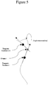
- the next step is the acquisition of the general curvature of the spine under different characteristic postures.
- the patient under study is subjected to a series of tests during which the general line of the column will be evaluated at the dorsal level.
- the positioning of the pelvis and shoulders will be necessary to define the orientations of the ends of the column.
- the patient will have to be, if necessary, maintained at the level of the pelvis to limit the intervention of the external members in the establishment of its general equilibrium, it will be carried out an acquisition with the help of a device, positions in the space of identifiable skin markers related to scoliotic vertebrae compared to a known reference frame.
- An acquisition will be carried out patient at rest in conditions as close as possible to the conditions of taking the radiography calibrated standing patient at rest.
- This acquisition will be used to determine the centerline of the vertebral bodies from the general line of the column. This is made possible by the fact that the calibrated radio can give the coordinates of all these points thanks to the sealed markers.
- the positioning of the vertebrae can therefore be determined according to the cutaneous marks for a given position, standing, at rest. It will then be established a corrected transformation between the skin markings and the positioning of the vertebrae taking into account the influence of the kinematics of the vertebrae with each other during the movements of the patient.
- the segmental masses and the mass centers are determined, and the moments and centers of mass are determined by vertebral level.
- the muscular action will be dissociated from the inter segmental action.
- the three points are sufficient to determine a common coordinate system in which the set of data is known, which thus makes it possible to define the transition matrix between the two recordings.
- the second step is to place the vertebrae on the spline. It is considered that the point of correspondence between the vertebra and the spline is the point of intersection of the Stockes marker (XY plane) with it.
- This method makes it possible to define also on the recordings of external acquisitions the position of the sacrum and the angle of the pelvis with the vertical, called sacred angle.
- the goal is to find a relationship linking the intervertebral angles.
- an analysis module has been added, tracing an intervertebral angle according to that which is "below" when one traverses the column from bottom to top.
- figure 6 illustrates an example of the relationships between the intervertebral angles in the frontal plane (abscissa in °; ordinate in °)
- This method makes it possible to define laws of behavior of the disk T1 / T2 with L5 / S1.
- the centers of rotation of one vertebra with respect to another are calculated from the different positions recorded in the frontal plane (bending) and sagittal (Flexion / extension).
- the points of the upper vertebra corresponding to each position are placed in the Stockes mark of the lower vertebra. These points then form a circular trajectory whose center of rotation is calculated by the least squares method.
- This method makes it possible to identify apparent and personalized centers of rotation verifying the experimental data obtained on a patient.
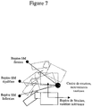
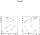
- FIG. 8 An example of calculating the centers of rotation on a scoliotic subject is illustrated on the figure 8 .
- centers of rotation are calculated in the overall reference of the radio. For each vertebra, two distinct centers of rotation are calculated in space, one for sagittal movements and one for frontal movements. These centers are then expressed in the reference Stokes of the lower vertebra to ensure repositioning in the solver.
- the variant angle is incremented by the calculation step (default 0.001)
- the angle is the value of the stop and the variant is the following angle
- the intervertebral angle i is incremented according to the angle i + 1
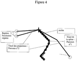
- the spine is until now simulated kinematically. This leads to a geometry of the spine representing the balance of the patient. It is interesting now to know the distribution of the forces exerted on the column, in order to build a complete mechanical model.
- the prior art has an approach for calculating efforts inspired by the anthropometric model. The principle of this approach is to cut the trunk into four slices attached to four specific parts of the spine and calculate their weight and center of gravity. The contour of each slice is obtained by sizing the generic pattern of the average population to the dimensions of the subject being measured.
- the method used in the model according to the invention is substantially different. Five crowns are recorded from contour records. These crowns are then discretized in 60 points. In a second step, these crowns are positioned relative to the column from the registration. This positioning is done by confusing the point on the skin, at the level of the vertebra associated with the crown, recorded by the registration curve with the point of the crown corresponding to the center of the back. The other crowns are then interpolated to obtain 18 crowns defining 17 vertically centered slices on the center of the vertebral body of the corresponding vertebra.
- the Figure 9 illustrates the interpolation of the crowns.
- the volume and the center of gravity of each slice thus defined is calculated by cutting them into elementary prisms.
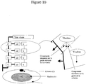
- the Figure 10 represents a model of mass distribution in the trunk. We then obtain the torsor of the forces on each vertebra depending solely on the geometry input. The viscera / hard body distribution for each slice is for the moment defined from a limited number of data. This distribution will be refined later.
Landscapes
- Medical Informatics (AREA)
- Engineering & Computer Science (AREA)
- Health & Medical Sciences (AREA)
- Public Health (AREA)
- Epidemiology (AREA)
- Databases & Information Systems (AREA)
- Pathology (AREA)
- Data Mining & Analysis (AREA)
- Biomedical Technology (AREA)
- General Health & Medical Sciences (AREA)
- Primary Health Care (AREA)
- Prostheses (AREA)
- Measuring And Recording Apparatus For Diagnosis (AREA)
- Measurement Of The Respiration, Hearing Ability, Form, And Blood Characteristics Of Living Organisms (AREA)
- Ultra Sonic Daignosis Equipment (AREA)
- Instructional Devices (AREA)
Claims (7)
- Verfahren zum Aufbauen eines digitalen Modells einer Einheit von Knochengelenken, wobei jedes Knochengelenk zwei Knochen, die durch ein Gelenk verbunden sind, eines gegebenen Patienten umfasst, das computergestützt ist und wobei:- der Computer mindestens ein dreidimensionales digitales Bezugsmodell der Einheit von Knochengelenken umfasst, wobei das Bezugsmodell mindestens zum Teil durch starre Körper dargestellt ist, die die Knochen modellieren und durch Gelenke in einer Bezugsposition verbunden sind;- die Geometrie des digitalen Modells, die der relativen Position in dem Raum jedes der starren Körper entspricht, durch spezifische geometrische Daten personalisiert ist, die direkt oder indirekt aus medizinischen Bildern des Patienten in der Bezugsposition stammen;- das digitale Modell mechanisch durch Änderungen von Parametern von Wechselwirkung, Mobilität oder Steifigkeit jedes der Gelenke, die die starren Körper verbinden, in Abhängigkeit von Merkmalen, die auf dem Patienten festgestellt werden, personalisiert wird;wobei die mechanische Personalisierung des digitalen Modells darin besteht:- Positionen in dem Raum eines Teils der starren Körper zu erfassen und anschließend die Positionen der anderen starren Körper durch Interpolation derart zu bestimmen, dass die relativen Positionen jedes der starren Körper des digitalen Modells erhalten werden;- die relativen Positionen, die einer allgemeinen Gleichgewichtsposition des Patienten entsprechen, die von der Bezugsposition unterschiedlich ist und aus der Anwendung mindestens einer bestimmten Belastung auf dem Patienten resultiert, zu messen;- für jedes Paar starrer Körper analytische Funktionen zu berechnen, die es erlauben, die Wechselwirkungsparameter zu approximieren, und die, an das digitale Modell angewandt, ausgehend von der Bezugsposition zu den gemessenen relativen Positionen führen, die der Gleichgewichtsposition entsprechen, die aus dem Anwenden der mindestens einen Belastung auf dem Patienten resultiert.
- Verfahren zum Aufbauen eines digitalen Modells einer Einheit von Knochengelenken nach Anspruch 1, dadurch gekennzeichnet, dass das digitale Modell durch geometrische Positionsparameter der starren Körper und durch Steifigkeitsparameter der Gelenke, die die starren Körper verbinden, definiert ist.
- Verfahren zum Aufbauen eines digitalen Modells einer Einheit von Knochengelenken nach Anspruch 1 oder 2, dadurch gekennzeichnet, dass es einen Darstellungsschritt des Resultats einer Belastung umfasst, der darin besteht, die Kräfte in der Einheit von Knochengelenken des personalisierten Modells in Gleichgewichtsposition, die aus einer Einheit simulierter Belastungen, die auf das Implantieren einer Prothese oder eines Implantats zurückzuführen sind, resultieren, die mindestens eine statische Belastung umfasst, die auf mindestens zwei starre Körper ausgeübt wird und eine relative Positionierung mit einer unterschiedlichen Mobilität oder Steifigkeit von der, die dem Verhaltensgesetz entspricht, neu zu berechnen.
- Verfahren zum Aufbauen eines digitalen Modells einer Einheit von Knochengelenken nach den Ansprüchen 1 und 2, dadurch gekennzeichnet, dass es einen Aufzeichnungsschritt des digitalen Bezugsmodells der Einheit von Gelenken umfasst, der darin besteht, ein Abwechseln starrer Körper und Gelenke zu definieren, und für jedes der Paare von Körpern eine Einheit digitaler Parameter zu definieren, die die Mobilität oder Steifigkeit insgesamt charakterisieren, die aus der Aktion der Einheit von Zwischenelementen, den Bandscheiben und Verbindungselementen, den Ligamenten, die sich auf die Wechselwirkungsparameter der Steifigkeit zwischen den zwei Körpern auswirken, resultieren.
- Verfahren zum Aufbauen eines digitalen Modells einer Einheit von Knochengelenken nach mindestens einem der vorstehenden Ansprüche, dadurch gekennzeichnet, dass der Personalisierungsschritt darin besteht, mindestens ein Bild der Einheit von Gelenken eines gegebenen Patienten zu erfassen, aus dem Bild die Informationen zu extrahieren, die für das Aufbauen eines realen Modells durch Erkennen der Position der Gelenke, die in dem Bild sichtbar sind, erforderlich sind, und das Standardmodell in Abhängigkeit von dem realen Modell zu modifizieren.
- Verfahren zum Aufbauen eines digitalen Modells einer Einheit von Knochengelenken nach mindestens einem der vorstehenden Ansprüche, dadurch gekennzeichnet, dass der Aufzeichnungsschritt des digitalen Modells darin besteht, eine Standardeinheit digitaler Daten zu definieren, die für jedes der dargestellten Gelenke in Form eines starren Körpers Folgendes umfasst:- einen ersten geometrischen Bezugspositionsdeskriptor, der der Geometrie der Einheit von Gelenken für einen Standardpatienten in einer Bezugsposition entspricht, wobei der Deskriptor für jeden starren Körper bezüglich einem benachbarten Körper bestimmt wird;- einen zweiten mechanischen Wechselwirkungsdeskriptor mit jedem der benachbarten Körper, wobei der mechanische Deskriptor für das Verhaltensgesetz repräsentativ ist, wenn die Gruppe von Gelenken der Wirkung mindestens einer äußeren Belastung unterzogen wird;wobei der Personalisierungsschritt darin besteht, die Standardeinheit von Daten durch personalisierte Daten zu ändern.
- Verfahren zum Aufbauen eines digitalen Modells einer Einheit von Knochengelenken nach mindestens einem der vorstehenden Ansprüche, dadurch gekennzeichnet, dass es außerdem einen Abstimmungsschritt umfasst, der darin bestimmt, die Röntgenbilddaten und Daten externer Erfassung in Übereinstimmung zu bringen, wobei dieser Schritt in zwei Unterschritte gegliedert ist:- Abstimmen der Röntgenrekonstruktion bezüglich der 3D-Kurve, die aus den Daten externer Erfassung in derselben Position hervorgehen;- Bestimmen der Verteilung der Punkte der 3D-Kurve, die mit den Wirbeln assoziiert sind, die in der Stokes-Kennzeichnung positioniert sind, und ihrer dazugehörenden Tangente.
Applications Claiming Priority (3)
| Application Number | Priority Date | Filing Date | Title |
|---|---|---|---|
| FR0216846A FR2849516B1 (fr) | 2002-12-30 | 2002-12-30 | Procede de simulation biomecanique d'un ensemble d'articulations osseuses |
| FR0216846 | 2002-12-30 | ||
| PCT/FR2003/003943 WO2004061721A2 (fr) | 2002-12-30 | 2003-12-30 | Procede de simulation biomecanique d'un ensemble d'articulations osseuses |
Publications (2)
| Publication Number | Publication Date |
|---|---|
| EP1579354A2 EP1579354A2 (de) | 2005-09-28 |
| EP1579354B1 true EP1579354B1 (de) | 2019-07-24 |
Family
ID=32480278
Family Applications (1)
| Application Number | Title | Priority Date | Filing Date |
|---|---|---|---|
| EP03814510.8A Expired - Lifetime EP1579354B1 (de) | 2002-12-30 | 2003-12-30 | Verfahren zur biomechanischen simulation einer gruppe von gelenken |
Country Status (6)
| Country | Link |
|---|---|
| US (1) | US20070093998A1 (de) |
| EP (1) | EP1579354B1 (de) |
| CN (1) | CN100576210C (de) |
| AU (1) | AU2003303663A1 (de) |
| FR (1) | FR2849516B1 (de) |
| WO (1) | WO2004061721A2 (de) |
Families Citing this family (36)
| Publication number | Priority date | Publication date | Assignee | Title |
|---|---|---|---|---|
| CN1846606B (zh) * | 2006-05-09 | 2010-10-06 | 重庆大学 | 模拟关节腔复合机械应力细胞加载装置 |
| FR2909791B1 (fr) * | 2006-12-07 | 2009-02-13 | Ecole Nale Sup Artes Metiers | Procede de simulation du comportement d'un ensemble osseux articule |
| DE102007023552B4 (de) * | 2007-05-21 | 2015-02-12 | Siemens Aktiengesellschaft | Kombiniertes Bildgebungsverfahren |
| EP2149123B1 (de) * | 2007-05-25 | 2013-06-05 | Ecole Nationale Supérieure D'Arts et Métiers ENSAM | Verfahren zur rekonstruktion eines dreidimensionalen modells einer körperstruktur |
| EP2164393A2 (de) * | 2007-07-06 | 2010-03-24 | Markus Heller | Verfahren zum ermitteln von für die charakterisierung von gelenkbewegungen relevanten informationen |
| US20090093852A1 (en) * | 2007-10-05 | 2009-04-09 | Hynes Richard A | Spinal stabilization treatment methods for maintaining axial spine height and sagital plane spine balance |
| US8549888B2 (en) | 2008-04-04 | 2013-10-08 | Nuvasive, Inc. | System and device for designing and forming a surgical implant |
| DE102008049563A1 (de) * | 2008-09-30 | 2010-04-08 | Siemens Aktiengesellschaft | Verfahren zur Auswertung wenigstens eines Bilddatensatzes |
| EP2538885A1 (de) * | 2010-02-26 | 2013-01-02 | spontech spine intelligence group AG | Computerprogramm zur wirbelsäulenmobilitätssimulation und wirbelsäulensimulationsverfahren |
| CN103153239B (zh) | 2010-08-13 | 2017-11-21 | 史密夫和内修有限公司 | 用于优化骨科流程参数的系统和方法 |
| US8666719B2 (en) * | 2011-10-25 | 2014-03-04 | Livermore Software Technology Corp. | Methods and systems for numerically simulating muscle movements along bones and around joints |
| US11207132B2 (en) | 2012-03-12 | 2021-12-28 | Nuvasive, Inc. | Systems and methods for performing spinal surgery |
| US8903496B2 (en) | 2012-08-31 | 2014-12-02 | Greatbatch Ltd. | Clinician programming system and method |
| US9615788B2 (en) | 2012-08-31 | 2017-04-11 | Nuvectra Corporation | Method and system of producing 2D representations of 3D pain and stimulation maps and implant models on a clinician programmer |
| US9180302B2 (en) | 2012-08-31 | 2015-11-10 | Greatbatch Ltd. | Touch screen finger position indicator for a spinal cord stimulation programming device |
| US9507912B2 (en) | 2012-08-31 | 2016-11-29 | Nuvectra Corporation | Method and system of simulating a pulse generator on a clinician programmer |
| US8761897B2 (en) | 2012-08-31 | 2014-06-24 | Greatbatch Ltd. | Method and system of graphical representation of lead connector block and implantable pulse generators on a clinician programmer |
| US9375582B2 (en) | 2012-08-31 | 2016-06-28 | Nuvectra Corporation | Touch screen safety controls for clinician programmer |
| US9594877B2 (en) | 2012-08-31 | 2017-03-14 | Nuvectra Corporation | Virtual reality representation of medical devices |
| US8983616B2 (en) | 2012-09-05 | 2015-03-17 | Greatbatch Ltd. | Method and system for associating patient records with pulse generators |
| US8868199B2 (en) | 2012-08-31 | 2014-10-21 | Greatbatch Ltd. | System and method of compressing medical maps for pulse generator or database storage |
| US9471753B2 (en) | 2012-08-31 | 2016-10-18 | Nuvectra Corporation | Programming and virtual reality representation of stimulation parameter Groups |
| US10668276B2 (en) | 2012-08-31 | 2020-06-02 | Cirtec Medical Corp. | Method and system of bracketing stimulation parameters on clinician programmers |
| US9259577B2 (en) | 2012-08-31 | 2016-02-16 | Greatbatch Ltd. | Method and system of quick neurostimulation electrode configuration and positioning |
| US8812125B2 (en) | 2012-08-31 | 2014-08-19 | Greatbatch Ltd. | Systems and methods for the identification and association of medical devices |
| US9767255B2 (en) | 2012-09-05 | 2017-09-19 | Nuvectra Corporation | Predefined input for clinician programmer data entry |
| US8757485B2 (en) | 2012-09-05 | 2014-06-24 | Greatbatch Ltd. | System and method for using clinician programmer and clinician programming data for inventory and manufacturing prediction and control |
| US9848922B2 (en) | 2013-10-09 | 2017-12-26 | Nuvasive, Inc. | Systems and methods for performing spine surgery |
| CN105611884B (zh) | 2013-10-09 | 2019-06-28 | 纽文思公司 | 在手术脊椎程序期间术中设计并评定脊椎畸形矫正的系统 |
| CN110367988A (zh) | 2014-06-17 | 2019-10-25 | 纽文思公司 | 手术脊椎程序期间手术中计划和评估脊椎变形矫正的装置 |
| US9913669B1 (en) | 2014-10-17 | 2018-03-13 | Nuvasive, Inc. | Systems and methods for performing spine surgery |
| CN107077522A (zh) * | 2017-01-20 | 2017-08-18 | 无限极(中国)有限公司 | 一种青少年枕生物力学性能分析及设计优化方法及装置 |
| US11666384B2 (en) * | 2019-01-14 | 2023-06-06 | Nuvasive, Inc. | Prediction of postoperative global sagittal alignment based on full-body musculoskeletal modeling and posture optimization |
| US11791053B2 (en) | 2019-07-11 | 2023-10-17 | Silicospine Inc. | Method and system for simulating intervertebral disc pathophysiology |
| US20230329794A1 (en) * | 2020-09-22 | 2023-10-19 | Smith & Nephew, Inc. | Systems and methods for hip modeling and simulation |
| EP4657449A1 (de) * | 2024-05-31 | 2025-12-03 | Mdsim | Vorrichtung und verfahren zur erzeugung eines biomechanischen 3d-modells einer wirbelsäule eines patienten und unterstützung eines benutzers bei der planung einer wirbelsäulenbehandlung für die wirbelsäule eines patienten |
Family Cites Families (6)
| Publication number | Priority date | Publication date | Assignee | Title |
|---|---|---|---|---|
| US5625577A (en) * | 1990-12-25 | 1997-04-29 | Shukyohojin, Kongo Zen Sohonzan Shorinji | Computer-implemented motion analysis method using dynamics |
| US5835693A (en) * | 1994-07-22 | 1998-11-10 | Lynch; James D. | Interactive system for simulation and display of multi-body systems in three dimensions |
| US6205411B1 (en) * | 1997-02-21 | 2001-03-20 | Carnegie Mellon University | Computer-assisted surgery planner and intra-operative guidance system |
| EP1437100A1 (de) * | 1998-05-28 | 2004-07-14 | Orthosoft Inc. | Interaktive Benutzerschnittstelle für ein Computersystem für die Chirurgie |
| US20050018885A1 (en) * | 2001-05-31 | 2005-01-27 | Xuesong Chen | System and method of anatomical modeling |
| US7634306B2 (en) * | 2002-02-13 | 2009-12-15 | Kinamed, Inc. | Non-image, computer assisted navigation system for joint replacement surgery with modular implant system |
-
2002
- 2002-12-30 FR FR0216846A patent/FR2849516B1/fr not_active Expired - Fee Related
-
2003
- 2003-12-30 WO PCT/FR2003/003943 patent/WO2004061721A2/fr not_active Ceased
- 2003-12-30 AU AU2003303663A patent/AU2003303663A1/en not_active Abandoned
- 2003-12-30 CN CN200380110073A patent/CN100576210C/zh not_active Expired - Fee Related
- 2003-12-30 EP EP03814510.8A patent/EP1579354B1/de not_active Expired - Lifetime
- 2003-12-30 US US10/541,250 patent/US20070093998A1/en not_active Abandoned
Non-Patent Citations (1)
| Title |
|---|
| None * |
Also Published As
| Publication number | Publication date |
|---|---|
| WO2004061721A3 (fr) | 2005-01-13 |
| FR2849516B1 (fr) | 2009-01-09 |
| AU2003303663A1 (en) | 2004-07-29 |
| US20070093998A1 (en) | 2007-04-26 |
| EP1579354A2 (de) | 2005-09-28 |
| WO2004061721A2 (fr) | 2004-07-22 |
| CN1757035A (zh) | 2006-04-05 |
| CN100576210C (zh) | 2009-12-30 |
| FR2849516A1 (fr) | 2004-07-02 |
| AU2003303663A8 (en) | 2004-07-29 |
Similar Documents
| Publication | Publication Date | Title |
|---|---|---|
| EP1579354B1 (de) | Verfahren zur biomechanischen simulation einer gruppe von gelenken | |
| US12089900B2 (en) | Systems and methods for modeling spines and treating spines based on spine models | |
| US12256999B2 (en) | Planning spinal surgery using patient-specific biomechanical parameters | |
| US10874460B2 (en) | Systems and methods for modeling spines and treating spines based on spine models | |
| US11207135B2 (en) | Systems and methods for modeling spines and treating spines based on spine models | |
| US12201440B2 (en) | Assessment of spinal column integrity | |
| CN102770093B (zh) | 用于脊柱移动性模拟的计算机程序及脊柱模拟方法 | |
| US7236817B2 (en) | Animation technology | |
| Ćuković et al. | Supporting diagnosis and treatment of scoliosis: using augmented reality to calculate 3D spine models in real-time-ARScoliosis | |
| JP3996628B2 (ja) | ヒト中枢神経系への損傷を測定するためのコンピュータシミュレーションモデル | |
| Mandel et al. | Image-guided tethering spine surgery with outcome prediction using spatio-temporal dynamic networks | |
| Vendeuvre et al. | Biomechanical Insights and Innovations in Spinal Pathology and Surgical Interventions | |
| Zhang et al. | Development and model form assessment of an automatic subject-specific vertebra reconstruction method | |
| Deliège | Translating numerical predictive tools for the correction of craniosynostosis into clinical practice | |
| AU2001237138B2 (en) | Animation technology | |
| Khani | Automatic Analysis of the Scoliotic Trunk for Surgery Planning and Outcome Assessment | |
| CN121552683A (zh) | 一种3d打印踝关节abs骨模型 | |
| CN120051251A (zh) | 用于评估脊柱植入物的适合性的装置、方法和系统 | |
| Drapikowski et al. | Examination of the Impact of Vertebral Displacement on the Surface Area of Intervertebral Foramina | |
| Pröll | Data acquisition and motion interpolation for a multimodal medical training environment | |
| AU2001237138A1 (en) | Animation technology |
Legal Events
| Date | Code | Title | Description |
|---|---|---|---|
| PUAI | Public reference made under article 153(3) epc to a published international application that has entered the european phase |
Free format text: ORIGINAL CODE: 0009012 |
|
| 17P | Request for examination filed |
Effective date: 20050701 |
|
| AK | Designated contracting states |
Kind code of ref document: A2 Designated state(s): AT BE BG CH CY CZ DE DK EE ES FI FR GB GR HU IE IT LI LU MC NL PT RO SE SI SK TR |
|
| AX | Request for extension of the european patent |
Extension state: AL LT LV MK |
|
| DAX | Request for extension of the european patent (deleted) | ||
| RIN1 | Information on inventor provided before grant (corrected) |
Inventor name: ELBAROUDI, FOUAD |
|
| RAP1 | Party data changed (applicant data changed or rights of an application transferred) |
Owner name: AXS INGENIERIE |
|
| 17Q | First examination report despatched |
Effective date: 20160229 |
|
| RAP1 | Party data changed (applicant data changed or rights of an application transferred) |
Owner name: AXS MEDICAL |
|
| STAA | Information on the status of an ep patent application or granted ep patent |
Free format text: STATUS: EXAMINATION IS IN PROGRESS |
|
| REG | Reference to a national code |
Ref country code: DE Ref legal event code: R079 Ref document number: 60352152 Country of ref document: DE Free format text: PREVIOUS MAIN CLASS: G06F0017500000 Ipc: G06Q0050220000 |
|
| GRAP | Despatch of communication of intention to grant a patent |
Free format text: ORIGINAL CODE: EPIDOSNIGR1 |
|
| STAA | Information on the status of an ep patent application or granted ep patent |
Free format text: STATUS: GRANT OF PATENT IS INTENDED |
|
| RIC1 | Information provided on ipc code assigned before grant |
Ipc: G06Q 50/22 20180101AFI20190205BHEP Ipc: G16H 50/50 20180101ALI20190205BHEP |
|
| INTG | Intention to grant announced |
Effective date: 20190301 |
|
| GRAS | Grant fee paid |
Free format text: ORIGINAL CODE: EPIDOSNIGR3 |
|
| GRAA | (expected) grant |
Free format text: ORIGINAL CODE: 0009210 |
|
| STAA | Information on the status of an ep patent application or granted ep patent |
Free format text: STATUS: THE PATENT HAS BEEN GRANTED |
|
| AK | Designated contracting states |
Kind code of ref document: B1 Designated state(s): AT BE BG CH CY CZ DE DK EE ES FI FR GB GR HU IE IT LI LU MC NL PT RO SE SI SK TR |
|
| REG | Reference to a national code |
Ref country code: GB Ref legal event code: FG4D Free format text: NOT ENGLISH |
|
| REG | Reference to a national code |
Ref country code: CH Ref legal event code: EP |
|
| REG | Reference to a national code |
Ref country code: DE Ref legal event code: R096 Ref document number: 60352152 Country of ref document: DE |
|
| REG | Reference to a national code |
Ref country code: AT Ref legal event code: REF Ref document number: 1159097 Country of ref document: AT Kind code of ref document: T Effective date: 20190815 |
|
| REG | Reference to a national code |
Ref country code: IE Ref legal event code: FG4D Free format text: LANGUAGE OF EP DOCUMENT: FRENCH |
|
| REG | Reference to a national code |
Ref country code: NL Ref legal event code: MP Effective date: 20190724 |
|
| REG | Reference to a national code |
Ref country code: AT Ref legal event code: MK05 Ref document number: 1159097 Country of ref document: AT Kind code of ref document: T Effective date: 20190724 |
|
| PG25 | Lapsed in a contracting state [announced via postgrant information from national office to epo] |
Ref country code: FI Free format text: LAPSE BECAUSE OF FAILURE TO SUBMIT A TRANSLATION OF THE DESCRIPTION OR TO PAY THE FEE WITHIN THE PRESCRIBED TIME-LIMIT Effective date: 20190724 Ref country code: SE Free format text: LAPSE BECAUSE OF FAILURE TO SUBMIT A TRANSLATION OF THE DESCRIPTION OR TO PAY THE FEE WITHIN THE PRESCRIBED TIME-LIMIT Effective date: 20190724 Ref country code: NL Free format text: LAPSE BECAUSE OF FAILURE TO SUBMIT A TRANSLATION OF THE DESCRIPTION OR TO PAY THE FEE WITHIN THE PRESCRIBED TIME-LIMIT Effective date: 20190724 Ref country code: AT Free format text: LAPSE BECAUSE OF FAILURE TO SUBMIT A TRANSLATION OF THE DESCRIPTION OR TO PAY THE FEE WITHIN THE PRESCRIBED TIME-LIMIT Effective date: 20190724 Ref country code: PT Free format text: LAPSE BECAUSE OF FAILURE TO SUBMIT A TRANSLATION OF THE DESCRIPTION OR TO PAY THE FEE WITHIN THE PRESCRIBED TIME-LIMIT Effective date: 20191125 Ref country code: BG Free format text: LAPSE BECAUSE OF FAILURE TO SUBMIT A TRANSLATION OF THE DESCRIPTION OR TO PAY THE FEE WITHIN THE PRESCRIBED TIME-LIMIT Effective date: 20191024 |
|
| PG25 | Lapsed in a contracting state [announced via postgrant information from national office to epo] |
Ref country code: ES Free format text: LAPSE BECAUSE OF FAILURE TO SUBMIT A TRANSLATION OF THE DESCRIPTION OR TO PAY THE FEE WITHIN THE PRESCRIBED TIME-LIMIT Effective date: 20190724 Ref country code: GR Free format text: LAPSE BECAUSE OF FAILURE TO SUBMIT A TRANSLATION OF THE DESCRIPTION OR TO PAY THE FEE WITHIN THE PRESCRIBED TIME-LIMIT Effective date: 20191025 |
|
| PG25 | Lapsed in a contracting state [announced via postgrant information from national office to epo] |
Ref country code: TR Free format text: LAPSE BECAUSE OF FAILURE TO SUBMIT A TRANSLATION OF THE DESCRIPTION OR TO PAY THE FEE WITHIN THE PRESCRIBED TIME-LIMIT Effective date: 20190724 |
|
| PG25 | Lapsed in a contracting state [announced via postgrant information from national office to epo] |
Ref country code: DK Free format text: LAPSE BECAUSE OF FAILURE TO SUBMIT A TRANSLATION OF THE DESCRIPTION OR TO PAY THE FEE WITHIN THE PRESCRIBED TIME-LIMIT Effective date: 20190724 Ref country code: EE Free format text: LAPSE BECAUSE OF FAILURE TO SUBMIT A TRANSLATION OF THE DESCRIPTION OR TO PAY THE FEE WITHIN THE PRESCRIBED TIME-LIMIT Effective date: 20190724 Ref country code: RO Free format text: LAPSE BECAUSE OF FAILURE TO SUBMIT A TRANSLATION OF THE DESCRIPTION OR TO PAY THE FEE WITHIN THE PRESCRIBED TIME-LIMIT Effective date: 20190724 Ref country code: IT Free format text: LAPSE BECAUSE OF FAILURE TO SUBMIT A TRANSLATION OF THE DESCRIPTION OR TO PAY THE FEE WITHIN THE PRESCRIBED TIME-LIMIT Effective date: 20190724 |
|
| PG25 | Lapsed in a contracting state [announced via postgrant information from national office to epo] |
Ref country code: SK Free format text: LAPSE BECAUSE OF FAILURE TO SUBMIT A TRANSLATION OF THE DESCRIPTION OR TO PAY THE FEE WITHIN THE PRESCRIBED TIME-LIMIT Effective date: 20190724 Ref country code: CZ Free format text: LAPSE BECAUSE OF FAILURE TO SUBMIT A TRANSLATION OF THE DESCRIPTION OR TO PAY THE FEE WITHIN THE PRESCRIBED TIME-LIMIT Effective date: 20190724 |
|
| REG | Reference to a national code |
Ref country code: DE Ref legal event code: R097 Ref document number: 60352152 Country of ref document: DE |
|
| PLBE | No opposition filed within time limit |
Free format text: ORIGINAL CODE: 0009261 |
|
| STAA | Information on the status of an ep patent application or granted ep patent |
Free format text: STATUS: NO OPPOSITION FILED WITHIN TIME LIMIT |
|
| 26N | No opposition filed |
Effective date: 20200603 |
|
| PG25 | Lapsed in a contracting state [announced via postgrant information from national office to epo] |
Ref country code: SI Free format text: LAPSE BECAUSE OF FAILURE TO SUBMIT A TRANSLATION OF THE DESCRIPTION OR TO PAY THE FEE WITHIN THE PRESCRIBED TIME-LIMIT Effective date: 20190724 Ref country code: MC Free format text: LAPSE BECAUSE OF FAILURE TO SUBMIT A TRANSLATION OF THE DESCRIPTION OR TO PAY THE FEE WITHIN THE PRESCRIBED TIME-LIMIT Effective date: 20190724 |
|
| PG25 | Lapsed in a contracting state [announced via postgrant information from national office to epo] |
Ref country code: LU Free format text: LAPSE BECAUSE OF NON-PAYMENT OF DUE FEES Effective date: 20191230 |
|
| PGFP | Annual fee paid to national office [announced via postgrant information from national office to epo] |
Ref country code: FR Payment date: 20201208 Year of fee payment: 18 Ref country code: GB Payment date: 20201228 Year of fee payment: 18 Ref country code: IE Payment date: 20201228 Year of fee payment: 18 |
|
| PGFP | Annual fee paid to national office [announced via postgrant information from national office to epo] |
Ref country code: BE Payment date: 20201228 Year of fee payment: 18 |
|
| PGFP | Annual fee paid to national office [announced via postgrant information from national office to epo] |
Ref country code: CH Payment date: 20210106 Year of fee payment: 18 |
|
| PG25 | Lapsed in a contracting state [announced via postgrant information from national office to epo] |
Ref country code: CY Free format text: LAPSE BECAUSE OF FAILURE TO SUBMIT A TRANSLATION OF THE DESCRIPTION OR TO PAY THE FEE WITHIN THE PRESCRIBED TIME-LIMIT Effective date: 20190724 |
|
| PGFP | Annual fee paid to national office [announced via postgrant information from national office to epo] |
Ref country code: DE Payment date: 20201229 Year of fee payment: 18 |
|
| PG25 | Lapsed in a contracting state [announced via postgrant information from national office to epo] |
Ref country code: HU Free format text: LAPSE BECAUSE OF FAILURE TO SUBMIT A TRANSLATION OF THE DESCRIPTION OR TO PAY THE FEE WITHIN THE PRESCRIBED TIME-LIMIT; INVALID AB INITIO Effective date: 20031230 |
|
| REG | Reference to a national code |
Ref country code: DE Ref legal event code: R119 Ref document number: 60352152 Country of ref document: DE |
|
| REG | Reference to a national code |
Ref country code: CH Ref legal event code: PL |
|
| GBPC | Gb: european patent ceased through non-payment of renewal fee |
Effective date: 20211230 |
|
| REG | Reference to a national code |
Ref country code: BE Ref legal event code: MM Effective date: 20211231 |
|
| PG25 | Lapsed in a contracting state [announced via postgrant information from national office to epo] |
Ref country code: IE Free format text: LAPSE BECAUSE OF NON-PAYMENT OF DUE FEES Effective date: 20211230 Ref country code: GB Free format text: LAPSE BECAUSE OF NON-PAYMENT OF DUE FEES Effective date: 20211230 Ref country code: DE Free format text: LAPSE BECAUSE OF NON-PAYMENT OF DUE FEES Effective date: 20220701 |
|
| PG25 | Lapsed in a contracting state [announced via postgrant information from national office to epo] |
Ref country code: FR Free format text: LAPSE BECAUSE OF NON-PAYMENT OF DUE FEES Effective date: 20211231 Ref country code: BE Free format text: LAPSE BECAUSE OF NON-PAYMENT OF DUE FEES Effective date: 20211231 |
|
| PG25 | Lapsed in a contracting state [announced via postgrant information from national office to epo] |
Ref country code: LI Free format text: LAPSE BECAUSE OF NON-PAYMENT OF DUE FEES Effective date: 20211231 Ref country code: CH Free format text: LAPSE BECAUSE OF NON-PAYMENT OF DUE FEES Effective date: 20211231 |