EP1579354B1 - Method for biomechanically simulating a set of osseous joints - Google Patents
Method for biomechanically simulating a set of osseous joints Download PDFInfo
- Publication number
- EP1579354B1 EP1579354B1 EP03814510.8A EP03814510A EP1579354B1 EP 1579354 B1 EP1579354 B1 EP 1579354B1 EP 03814510 A EP03814510 A EP 03814510A EP 1579354 B1 EP1579354 B1 EP 1579354B1
- Authority
- EP
- European Patent Office
- Prior art keywords
- joints
- patient
- model
- digital model
- osseous
- Prior art date
- Legal status (The legal status is an assumption and is not a legal conclusion. Google has not performed a legal analysis and makes no representation as to the accuracy of the status listed.)
- Expired - Lifetime
Links
- 238000000034 method Methods 0.000 title claims description 37
- 239000007943 implant Substances 0.000 claims description 13
- 238000009826 distribution Methods 0.000 claims description 12
- 230000003993 interaction Effects 0.000 claims description 12
- 230000009471 action Effects 0.000 claims description 11
- 210000000988 bone and bone Anatomy 0.000 claims description 11
- 238000002513 implantation Methods 0.000 claims description 6
- 230000000694 effects Effects 0.000 claims description 4
- 238000010276 construction Methods 0.000 claims description 3
- 230000006870 function Effects 0.000 claims description 3
- 210000003041 ligament Anatomy 0.000 claims description 2
- 238000012986 modification Methods 0.000 claims description 2
- 230000004048 modification Effects 0.000 claims description 2
- 230000005477 standard model Effects 0.000 claims description 2
- 230000003068 static effect Effects 0.000 claims description 2
- 238000004088 simulation Methods 0.000 description 19
- 208000031968 Cadaver Diseases 0.000 description 10
- 230000037230 mobility Effects 0.000 description 10
- 238000013459 approach Methods 0.000 description 9
- 230000006399 behavior Effects 0.000 description 9
- 238000004364 calculation method Methods 0.000 description 9
- 238000004458 analytical method Methods 0.000 description 7
- 238000011282 treatment Methods 0.000 description 5
- 210000001835 viscera Anatomy 0.000 description 5
- 241000220257 Matthiola Species 0.000 description 4
- 235000011378 Matthiola incana Nutrition 0.000 description 4
- 238000001727 in vivo Methods 0.000 description 4
- 238000002601 radiography Methods 0.000 description 4
- 235000021547 stock Nutrition 0.000 description 4
- 230000005484 gravity Effects 0.000 description 3
- 210000004197 pelvis Anatomy 0.000 description 3
- 230000036544 posture Effects 0.000 description 3
- 238000012360 testing method Methods 0.000 description 3
- 241000700608 Sagitta Species 0.000 description 2
- 238000004422 calculation algorithm Methods 0.000 description 2
- 238000012937 correction Methods 0.000 description 2
- 238000011156 evaluation Methods 0.000 description 2
- 210000003205 muscle Anatomy 0.000 description 2
- 230000003387 muscular Effects 0.000 description 2
- 230000007170 pathology Effects 0.000 description 2
- 230000002980 postoperative effect Effects 0.000 description 2
- 210000004872 soft tissue Anatomy 0.000 description 2
- 239000007787 solid Substances 0.000 description 2
- 230000006641 stabilisation Effects 0.000 description 2
- 238000011105 stabilization Methods 0.000 description 2
- 238000001356 surgical procedure Methods 0.000 description 2
- 206010013786 Dry skin Diseases 0.000 description 1
- 208000007623 Lordosis Diseases 0.000 description 1
- 208000000875 Spinal Curvatures Diseases 0.000 description 1
- 241001080024 Telles Species 0.000 description 1
- 230000006978 adaptation Effects 0.000 description 1
- 210000003484 anatomy Anatomy 0.000 description 1
- 230000003190 augmentative effect Effects 0.000 description 1
- 238000005452 bending Methods 0.000 description 1
- 210000000748 cardiovascular system Anatomy 0.000 description 1
- 230000008859 change Effects 0.000 description 1
- 230000008878 coupling Effects 0.000 description 1
- 238000010168 coupling process Methods 0.000 description 1
- 238000005859 coupling reaction Methods 0.000 description 1
- 238000005520 cutting process Methods 0.000 description 1
- 238000007405 data analysis Methods 0.000 description 1
- 230000007423 decrease Effects 0.000 description 1
- 238000002059 diagnostic imaging Methods 0.000 description 1
- 238000006073 displacement reaction Methods 0.000 description 1
- 230000004064 dysfunction Effects 0.000 description 1
- 239000012636 effector Substances 0.000 description 1
- 239000004744 fabric Substances 0.000 description 1
- 230000036541 health Effects 0.000 description 1
- 230000002706 hydrostatic effect Effects 0.000 description 1
- 238000000338 in vitro Methods 0.000 description 1
- 230000002452 interceptive effect Effects 0.000 description 1
- 210000003127 knee Anatomy 0.000 description 1
- WABPQHHGFIMREM-UHFFFAOYSA-N lead(0) Chemical compound [Pb] WABPQHHGFIMREM-UHFFFAOYSA-N 0.000 description 1
- 238000012417 linear regression Methods 0.000 description 1
- 238000013507 mapping Methods 0.000 description 1
- 239000003550 marker Substances 0.000 description 1
- 239000011159 matrix material Substances 0.000 description 1
- 230000007246 mechanism Effects 0.000 description 1
- 239000003607 modifier Substances 0.000 description 1
- 230000003562 morphometric effect Effects 0.000 description 1
- 238000013425 morphometry Methods 0.000 description 1
- 238000005457 optimization Methods 0.000 description 1
- 230000008569 process Effects 0.000 description 1
- 238000012545 processing Methods 0.000 description 1
- 238000011160 research Methods 0.000 description 1
- 206010039722 scoliosis Diseases 0.000 description 1
- 238000004513 sizing Methods 0.000 description 1
- 210000001519 tissue Anatomy 0.000 description 1
- 238000012549 training Methods 0.000 description 1
- 230000009466 transformation Effects 0.000 description 1
- 230000007704 transition Effects 0.000 description 1
- 210000000689 upper leg Anatomy 0.000 description 1
- 210000000707 wrist Anatomy 0.000 description 1
Images


Classifications
-
- G—PHYSICS
- G16—INFORMATION AND COMMUNICATION TECHNOLOGY [ICT] SPECIALLY ADAPTED FOR SPECIFIC APPLICATION FIELDS
- G16H—HEALTHCARE INFORMATICS, i.e. INFORMATION AND COMMUNICATION TECHNOLOGY [ICT] SPECIALLY ADAPTED FOR THE HANDLING OR PROCESSING OF MEDICAL OR HEALTHCARE DATA
- G16H50/00—ICT specially adapted for medical diagnosis, medical simulation or medical data mining; ICT specially adapted for detecting, monitoring or modelling epidemics or pandemics
- G16H50/50—ICT specially adapted for medical diagnosis, medical simulation or medical data mining; ICT specially adapted for detecting, monitoring or modelling epidemics or pandemics for simulation or modelling of medical disorders
-
- G—PHYSICS
- G16—INFORMATION AND COMMUNICATION TECHNOLOGY [ICT] SPECIALLY ADAPTED FOR SPECIFIC APPLICATION FIELDS
- G16H—HEALTHCARE INFORMATICS, i.e. INFORMATION AND COMMUNICATION TECHNOLOGY [ICT] SPECIALLY ADAPTED FOR THE HANDLING OR PROCESSING OF MEDICAL OR HEALTHCARE DATA
- G16H30/00—ICT specially adapted for the handling or processing of medical images
- G16H30/20—ICT specially adapted for the handling or processing of medical images for handling medical images, e.g. DICOM, HL7 or PACS
Definitions
- the present invention relates to the field of biomedical simulation software.
- the present invention relates more particularly to a method of biomechanical simulation of a set of bone joints of a patient, including the spine. This method makes it possible to calculate, estimate and visualize the consequences of a surgical operation on a joint.
- the system has been developed for spine operations and in particular spinal stabilization techniques. In general, the system makes it possible to inform the surgeon about the state of equilibrium and the distribution of the forces in the patient's column before and after the simulation.
- the prior art already knows, by the US patent application US 5,995,738 , a device and a method for facilitating the implantation of artificial components into the joints.
- the invention describes devices and methods for determining an implant position for at least one artificial component in a joint and facilitating its implantation.
- the invention includes creating a model of the patient's joint and creating a model of the component to be implanted.
- the created models are used to simulate the movement of the patient's joint according to the position of the component.
- This document of the prior art therefore proposes a means of physical simulation and not virtual to analyze the movements of a joint and an implant.
- the invention relates to an apparatus for facilitating the implantation of an artificial component into a joint.
- the apparatus includes a geometric predictor and a biomechanical simulator of preoperative movement, i.e., a series of simulations is performed on the implant and the joint prior to performing the operation.
- the invention describes a method for analyzing and displaying the movements of a human being.
- the body of the subject is divided into a plurality of segments interconnected by joints. Once the body is modeled in this way, it is possible to simulate and analyze the movement of the subject.
- At least one command such as a shape command or a resolution plane command is defined for the articulated chain, and this command is used as a constraint taken up by the animation engine for the animation of the animation.
- the chain with inverse kinematics.
- Each command comprises at least two keys, each key comprising a pair consisting of an effector direction vector and an associated constraint.
- shape control keys the associated constraints include a list of preferred orientations of the members of the body.
- the associated constraints include a preferential orientation of the resolution plane.
- the present invention intends to overcome the disadvantages of the prior art by making it possible to simulate a local or global correction operation of vertebral column curvatures or vertebral implant placement from radiographic images, of series of acquisitions of characteristics. measured in vivo on the patient and an implant database.
- the present invention further allows the state of the column to be simulated immediately after the surgical operation.
- the present invention does not apply only to the spine. It also applies to other bone joints such as the knee.
- the invention consists of a computer-assisted surgical system, allowing the surgeon to simulate, preoperatively, the effects on the patient of the corrective surgery that he plans to implement.
- This system allows him to simulate several operating strategies, and offers the surgeon a tool to help choose the operating strategy that offers the best compromise between stabilization and mobility.
- the numerical model is defined by parameters of geometrical positions of the rigid bodies and by stiffness parameters of the joints connecting the rigid bodies.
- the step of representing the result of a constraint consists in recalculating the personalized model [in equilibrium position] resulting from a set of constraints [for example implantation of a prosthesis or an implant] comprising at least a static stress exerted on at least two rigid bodies, and imposing a relative positioning with a mobility or a stiffness different from that corresponding to the law of behavior.
- the step of recording the numerical model of the set of standard joints consists of defining an alternation of rigid bodies and articulations, and defining for each of the pairs of bodies a set of numerical parameters characterizing the mobility or global stiffness resulting from the action of all the intermediate elements [for example intervertebral discs] and connecting elements [for example ligaments] having an effect on the interaction parameters [stiffness] between the two bodies.
- the personalization step consists in acquiring at least one image of the set of articulations of a given patient, in extracting from said image the information necessary for constructing a real model. by recognizing the position of the visible joints in said image, and modifying the standard model according to said real model.
- the invention differs from known surgical guidance products used to assist the surgeon during his operation. Indeed, the invention consists in particular in modeling the vertebral column of the individual who will be operated, to simulate the implantation of the implant or prosthesis and calculate the equilibrium position of the individual once the implant or prosthesis is placed.
- the data processing being software
- the invention also relates to the software architecture implemented for the realization of the functional architecture.
- the software structure includes several database servers: a user database, a vertebra database, a patient database and an implant database.
- the data contained in these databases are interrogated and updated by different users in order to build the 3D model of the patient's column and then to simulate the consequences of implant placement.
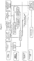
- the system according to the invention is a simulator of the biomechanical and kinematic consequences of the surgical act of treatment of spinal pathologies on the morphology of the patient.
- the Figure 2 represents the general architecture of the simulator.
- the simulator is a tool to help analyze the feasibility of the gesture. It allows to simulate the preoperative equilibrium, the corresponding inter-segmental efforts taking into account the effect of muscular and ligamentary rigidities, to apprehend the evolution of this equilibrium and of these postoperative efforts according to the curvatures introduced by the surgeon. during the operation. The surgeon will have to indicate as input the desired deformation of the instrumented zone. For this, a so-called "global" approach will be used.
- the power supply of the system can be manual (a user will supply the image files to the system) or automatic, the images are stored directly by the radiology devices and retrieved via an intranet / internet network.
- the specific points detected by the digitization will make it possible to calculate the 3D coordinates of the vertebrae (geometrical data).
- the geometric data from the digital images will allow to build a model of the patient's column in three dimensions.
- This model results the adaptation of a standard 3D model, predefined in the system, to the geometric characteristics of the patient.
- the user must be able to visualize the 3D model of the spine according to the frontal, sagittal and apical planes; moreover, it must be able to compare it to the radiographs used for its construction.
- the mechanical characteristics of the patient allow to customize the model.
- a standard geometric model of the vertebral column is enriched by the personal mechanical data of the patient concerned.
- the biomechanical characteristics of the patient's column are calculated from the patient's radiographs (before the first simulation), or from the model resulting from a simulation. Some parameters may be pre-calculated (sacral slope, angle of incidence, sagittal location, spinal curvature) on X-rays.
- the user must have the possibility to choose segments of column on which he imposes displacements.
- the user will be able to enter the values of certain clinical parameters that he wishes to simulate for a given segment.
- the user must be able to consult the mobilities or rigidities of the spine, the graduation will be standardized.
- the type of rod used to deform a segment can be selected from among several proposals (rigidity, diameter, etc.).
- the software Following a manipulation of the model by the user, the software must check the validity of the actions performed, and warn the user of any inconsistency (value impossible to obtain).
- the simulator must display the new curvatures of the model and the new position (stature) of the equilibrium of the patient. It must be possible to compare the curvature (s) with the initial curvature (s) (with the 3D model or radiograph).
- the user must be able to compare the rigidities of the spine before and after the simulation.
- Patient records containing the information concerning the simulation, must be able to be created by a user and maintained by the system, (backup of several simulations in the same file).
- the system must be able to remove or enter patient information (age, weight, size, etc.) into external data systems, subject to their existence.
- the rights and user profiles will make it possible to differentiate the functionalities available for each user. Depending on their rights and profiles, users will have access to different graphical interfaces. In addition, a preference system can be set up for each user (menu position, opening page, etc.), as well as a traceability mechanism, which will make it possible to follow the evolutions of a patient file.
- a user can have access to the input data, that is to say, to visualize, replace or modify the images used for the construction of the model, the digitized points or the operations carried out for the semi-automatic treatment of these images, the implants placed on the model, the mechanical characteristics of the patient ...
- the history of a simulation represents all the actions performed on a patient (parameters of the simulation). The user must be able to return to a past action (change an X-ray, re-enter the points for scanning, calculate new clinical parameters, or modify the actions performed during the simulation)
- the Figure 1 represents the architecture of the mechanical customization of the model.
- the digitization of the patient's X-rays allows us to obtain an accuracy of six points per vertebra. By extrapolating, we arrive at a precision of twelve points per vertebra.
- the next step is the acquisition of the general curvature of the spine under different characteristic postures.
- the patient under study is subjected to a series of tests during which the general line of the column will be evaluated at the dorsal level.
- the positioning of the pelvis and shoulders will be necessary to define the orientations of the ends of the column.
- the patient will have to be, if necessary, maintained at the level of the pelvis to limit the intervention of the external members in the establishment of its general equilibrium, it will be carried out an acquisition with the help of a device, positions in the space of identifiable skin markers related to scoliotic vertebrae compared to a known reference frame.
- An acquisition will be carried out patient at rest in conditions as close as possible to the conditions of taking the radiography calibrated standing patient at rest.
- This acquisition will be used to determine the centerline of the vertebral bodies from the general line of the column. This is made possible by the fact that the calibrated radio can give the coordinates of all these points thanks to the sealed markers.
- the positioning of the vertebrae can therefore be determined according to the cutaneous marks for a given position, standing, at rest. It will then be established a corrected transformation between the skin markings and the positioning of the vertebrae taking into account the influence of the kinematics of the vertebrae with each other during the movements of the patient.
- the segmental masses and the mass centers are determined, and the moments and centers of mass are determined by vertebral level.
- the muscular action will be dissociated from the inter segmental action.
- the three points are sufficient to determine a common coordinate system in which the set of data is known, which thus makes it possible to define the transition matrix between the two recordings.
- the second step is to place the vertebrae on the spline. It is considered that the point of correspondence between the vertebra and the spline is the point of intersection of the Stockes marker (XY plane) with it.
- This method makes it possible to define also on the recordings of external acquisitions the position of the sacrum and the angle of the pelvis with the vertical, called sacred angle.
- the goal is to find a relationship linking the intervertebral angles.
- an analysis module has been added, tracing an intervertebral angle according to that which is "below" when one traverses the column from bottom to top.
- figure 6 illustrates an example of the relationships between the intervertebral angles in the frontal plane (abscissa in °; ordinate in °)
- This method makes it possible to define laws of behavior of the disk T1 / T2 with L5 / S1.
- the centers of rotation of one vertebra with respect to another are calculated from the different positions recorded in the frontal plane (bending) and sagittal (Flexion / extension).
- the points of the upper vertebra corresponding to each position are placed in the Stockes mark of the lower vertebra. These points then form a circular trajectory whose center of rotation is calculated by the least squares method.
- This method makes it possible to identify apparent and personalized centers of rotation verifying the experimental data obtained on a patient.
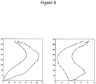
- FIG. 8 An example of calculating the centers of rotation on a scoliotic subject is illustrated on the figure 8 .
- centers of rotation are calculated in the overall reference of the radio. For each vertebra, two distinct centers of rotation are calculated in space, one for sagittal movements and one for frontal movements. These centers are then expressed in the reference Stokes of the lower vertebra to ensure repositioning in the solver.
- the variant angle is incremented by the calculation step (default 0.001)
- the angle is the value of the stop and the variant is the following angle
- the intervertebral angle i is incremented according to the angle i + 1
- the spine is until now simulated kinematically. This leads to a geometry of the spine representing the balance of the patient. It is interesting now to know the distribution of the forces exerted on the column, in order to build a complete mechanical model.
- the prior art has an approach for calculating efforts inspired by the anthropometric model. The principle of this approach is to cut the trunk into four slices attached to four specific parts of the spine and calculate their weight and center of gravity. The contour of each slice is obtained by sizing the generic pattern of the average population to the dimensions of the subject being measured.
- the method used in the model according to the invention is substantially different. Five crowns are recorded from contour records. These crowns are then discretized in 60 points. In a second step, these crowns are positioned relative to the column from the registration. This positioning is done by confusing the point on the skin, at the level of the vertebra associated with the crown, recorded by the registration curve with the point of the crown corresponding to the center of the back. The other crowns are then interpolated to obtain 18 crowns defining 17 vertically centered slices on the center of the vertebral body of the corresponding vertebra.
- the Figure 9 illustrates the interpolation of the crowns.
- the volume and the center of gravity of each slice thus defined is calculated by cutting them into elementary prisms.
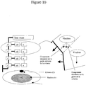
- the Figure 10 represents a model of mass distribution in the trunk. We then obtain the torsor of the forces on each vertebra depending solely on the geometry input. The viscera / hard body distribution for each slice is for the moment defined from a limited number of data. This distribution will be refined later.
Description
La présente invention se rapporte au domaine des logiciels de simulation biomédicale.The present invention relates to the field of biomedical simulation software.
La présente invention se rapporte plus particulièrement à un procédé de simulation biomécanique d'un ensemble d'articulations osseuses d'un patient, et notamment du rachis. Ce procédé permet de calculer, estimer et visualiser les conséquences d'une opération chirurgicale sur une articulation. Le système a été mis au point pour les opérations de la colonne vertébrale et en particulier les techniques de stabilisation de la colonne vertébrale. D'une manière générale, le système permet d'informer le chirurgien sur l'état de l'équilibre et la répartition des efforts dans la colonne du patient avant et après la simulation.The present invention relates more particularly to a method of biomechanical simulation of a set of bone joints of a patient, including the spine. This method makes it possible to calculate, estimate and visualize the consequences of a surgical operation on a joint. The system has been developed for spine operations and in particular spinal stabilization techniques. In general, the system makes it possible to inform the surgeon about the state of equilibrium and the distribution of the forces in the patient's column before and after the simulation.
L'art antérieur connaît déjà, par la demande de brevet américain
Il est proposé, dans la demande de brevet américain
Il est proposé, dans la demande de brevet américain
Il est également proposé, dans la demande de brevet
L'art antérieur connaît également, par la demande de brevet
Dans la publication scientifique
Enfin, l'art antérieur connaît, par la publication scientifique
Ces deux publications scientifiques traitent de problématiques différentes de celle de la présente invention. En particulier, elles ne mentionnent nullement d'étape de personnalisation d'un modèle numérique par particularisation des paramètres d'interaction [de mobilités ou caractéristiques de rigidités] de chacune des articulations reliant lesdits corps rigides en fonction des caractéristiques constatées sur le patient. Cette étape est fondamentale dans la présente invention.These two scientific publications deal with problems different from that of the present invention. In particular, they do not mention a step of customizing a numerical model by particularizing the interaction parameters [of mobility or characteristics of rigidities] of each of the joints connecting said rigid bodies according to the characteristics observed on the patient. This step is fundamental in the present invention.
La présente invention entend remédier aux inconvénients de l'art antérieur en permettant de simuler une opération de correction locale ou globale de courbures de la colonne vertébrale ou de pose d'implant vertébral à partir d'images radiographiques, de séries d'acquisitions de caractéristiques mesurées in vivo sur le patient et d'une base de données d'implants. La présente invention permet de plus de simuler l'état de la colonne juste après l'opération chirurgicale.The present invention intends to overcome the disadvantages of the prior art by making it possible to simulate a local or global correction operation of vertebral column curvatures or vertebral implant placement from radiographic images, of series of acquisitions of characteristics. measured in vivo on the patient and an implant database. The present invention further allows the state of the column to be simulated immediately after the surgical operation.
Bien entendu, la présente invention ne s'applique pas uniquement au rachis. Elle s'applique également à d'autres articulations osseuses comme le genou.Of course, the present invention does not apply only to the spine. It also applies to other bone joints such as the knee.
L'invention consiste en un système chirurgical assisté par ordinateur, permettant au chirurgien de simuler, en préopératoire, les effets sur le patient de la chirurgie correctrice qu'il envisage de mettre en application. Ce système lui permettant de simuler ainsi plusieurs stratégies opératoires, il offre au chirurgien un outil d'aide au choix de la stratégie opératoire offrant le meilleur compromis entre la stabilisation et la mobilité.The invention consists of a computer-assisted surgical system, allowing the surgeon to simulate, preoperatively, the effects on the patient of the corrective surgery that he plans to implement. This system allows him to simulate several operating strategies, and offers the surgeon a tool to help choose the operating strategy that offers the best compromise between stabilization and mobility.
A cet effet, la présente invention concerne dans son acception la plus générale un procédé de construction d'un modèle numérique d'un ensemble d'articulations osseuses d'un patient, notamment du rachis, chaque articulation osseuse comportant deux os reliés par une articulation, assisté par ordinateur et dans lequel :
- l'ordinateur comporte un modèle numérique tridimensionnel de référence de l'ensemble d'articulations osseuses représenté au moins en partie par des corps rigides modélisant les os et reliés par des articulations, dans une position de référence ;
- la géométrie dudit modèle numérique [position relative dans l'espace de chacun desdits corps rigides] est personnalisée par des données géométriques spécifiques issues directement ou indirectement d'images médicales du patient dans ladite position de référence [par exemple des radiographies du patient] ;
- ledit modèle numérique est personnalisé mécaniquement par des modifications des paramètres d'interaction [de mobilités ou caractéristiques de rigidité] de chacune des articulations reliant lesdits corps rigides en fonction de caractéristiques constatées sur le patient ;
- acquérir les positions dans l'espace d'une partie au moins des corps rigides, et à procéder à une interpolation pour déterminer la position calculée des autres corps rigides pour construire une table numérique comportant les positions relatives de chacun des corps rigides du modèle numérique ;
- mesurer des positions relatives correspondant à une position générale d'équilibre du patient [autre que la position de référence] et résultant de l'application d'au moins une contrainte déterminée sur ledit patient ;
- calculer, pour chaque couple de corps rigides, des fonctions analytiques permettant d'approximer les paramètres d'interaction [de mobilités ou caractéristiques de rigidité], et qui appliquées au modèle numérique depuis la position de référence conduisent aux positions relatives mesurées correspondant à la position d'équilibre résultant de l'application de l'au moins une contrainte sur le patient.
- the computer has a three-dimensional numerical reference model of the set of bone joints at least partly represented by rigid bodies modeling the bones and connected by articulations, in a reference position;
- the geometry of said numerical model [relative position in the space of each of said rigid bodies] is personalized by specific geometric data directly or indirectly derived from medical images of the patient in said reference position [for example X-rays of the patient];
- said digital model is mechanically customized by changes in the interaction parameters [of mobilities or stiffness characteristics] of each of the joints connecting said rigid bodies as a function of characteristics observed on the patient;
- acquiring the positions in the space of at least a portion of the rigid bodies, and interpolating to determine the computed position of the other rigid bodies to construct a numerical table including the relative positions of each of the rigid bodies of the numerical model;
- measuring relative positions corresponding to a general position of equilibrium of the patient [other than the reference position] and resulting from the application of at least one determined constraint on said patient;
- calculating, for each pair of rigid bodies, analytical functions making it possible to approximate the interaction parameters [of mobilities or stiffness characteristics], and which applied to the numerical model from the reference position lead to the measured relative positions corresponding to the position resulting equilibrium the application of the at least one constraint on the patient.
De préférence, le modèle numérique est défini par des paramètres de positions géométriques des corps rigides et par des paramètres de rigidité des articulations reliant les corps rigides.Preferably, the numerical model is defined by parameters of geometrical positions of the rigid bodies and by stiffness parameters of the joints connecting the rigid bodies.
Avantageusement, l'étape de représentation du résultat d'une contrainte consiste à recalculer le modèle personnalisé [en position d'équilibre] résultant d'un ensemble de contraintes [par exemple implantation d'une prothèse ou d'un implant] comprenant au moins une contrainte statique exercée sur au moins deux corps rigides, et imposant un positionnement relatif avec une mobilité ou une raideur différente de celle correspondant à la loi de comportement.Advantageously, the step of representing the result of a constraint consists in recalculating the personalized model [in equilibrium position] resulting from a set of constraints [for example implantation of a prosthesis or an implant] comprising at least a static stress exerted on at least two rigid bodies, and imposing a relative positioning with a mobility or a stiffness different from that corresponding to the law of behavior.
Selon une variante, l'étape d'enregistrement du modèle numérique de l'ensemble d'articulations standard consiste à définir une alternance de corps rigides et d' articulations, et à définir pour chacun des couples de corps un ensemble de paramètres numériques caractérisant la mobilité ou raideur globale résultant de l'action de l'ensemble des éléments intercalaires [par exemple disques intervertébraux] et des éléments de liaison [par exemple ligaments] ayant un effet sur les paramètres d'interaction [rigidités] entre les deux corps.According to one variant, the step of recording the numerical model of the set of standard joints consists of defining an alternation of rigid bodies and articulations, and defining for each of the pairs of bodies a set of numerical parameters characterizing the mobility or global stiffness resulting from the action of all the intermediate elements [for example intervertebral discs] and connecting elements [for example ligaments] having an effect on the interaction parameters [stiffness] between the two bodies.
Selon un mode de mise en oeuvre particulier, l'étape de personnalisation consiste à acquérir au moins une image de l'ensemble d'articulations d'un patient donné, à extraire de ladite image les informations nécessaires à la construction d'un modèle réel par reconnaissance de la position des articulations visibles dans ladite image, et de modifier le modèle standard en fonction dudit modèle réel.According to a particular embodiment, the personalization step consists in acquiring at least one image of the set of articulations of a given patient, in extracting from said image the information necessary for constructing a real model. by recognizing the position of the visible joints in said image, and modifying the standard model according to said real model.
Avantageusement, l'étape d'enregistrement d'un modèle numérique consiste à définir un ensemble standard de données numériques comprenant pour chacune des articulations représentées sous la forme d'un corps rigide :
- un premier descripteur géométrique de position de référence, correspondant à la géométrie de l'ensemble d'articulation pour un patient « standard » dans une position «de référence», ledit descripteur étant déterminé pour chaque corps rigide de façon relative par rapport à un corps adjacent ;
- un deuxième descripteur mécanique d'interaction avec chacun des corps adjacents, ledit descripteur mécanique étant représentatif de la loi de comportement lorsque l'ensemble d'articulation est soumis à l'action d'au moins une contrainte extérieure ;
- a first reference position geometric descriptor, corresponding to the geometry of the articulation assembly for a "standard" patient in a "reference" position, said descriptor being determined for each rigid body relative to a body adjacent;
- a second mechanical descriptor of interaction with each of the adjacent bodies, said mechanical descriptor being representative of the law of behavior when the hinge assembly is subjected to the action of at least one external constraint;
Selon un mode de mise en oeuvre particulier, le procédé comporte en outre une étape de recalage consistant à mettre en correspondance des données d'images radios et des données d'acquisition externe, cette étape se décomposant en deux sous-étapes :
- recalage de la reconstruction radio par rapport à la courbe 3D issue de données d'acquisition externe dans la même position ;
- détermination de la répartition des points de la courbe 3D associés aux vertèbres, positionnés dans le repère de Stokes et leur tangente associée.
- recalibration of the radio reconstruction with respect to the 3D curve derived from external acquisition data in the same position;
- determination of the distribution of the points of the 3D curve associated with the vertebrae, positioned in the Stokes coordinate system and their associated tangent.
On comprendra mieux l'invention à l'aide de la description, faite ci-après à titre purement explicatif, d'un mode de réalisation de l'invention, en référence aux figures annexées :
- la
figure 1 illustre l'architecture de la personnalisation mécanique du modèle ; - la
figure 2 représente l'architecture générale du simulateur selon un mode de réalisation de l'invention ; - la
figure 3 représente l'architecture du modèle selon un mode de mise en oeuvre de l'invention ; - la
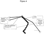
figure 4 illustre la mise en oeuvre du procédé de recalage ; - la
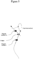
figure 5 illustre la définition des angles intervertébraux ; - la
figure 6 représente un exemple des relations entre les angles intervertébraux dans le plan frontal (abscisse en ° et ordonnée en °) ; - la
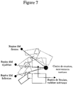
figure 7 illustre le calcul des centres de rotation ; - la
figure 8 représente un exemple de calcul des centres de rotation sur un sujet scoliotique ; - la
figure 9 illustre l'interpolation des couronnes ; et - la
figure 10 représente un modèle de répartition des masses dans le tronc.
- the
figure 1 illustrates the architecture of the mechanical customization of the model; - the
figure 2 represents the general architecture of the simulator according to one embodiment of the invention; - the
figure 3 represents the architecture of the model according to an embodiment of the invention; - the
figure 4 illustrates the implementation of the registration process; - the
figure 5 illustrates the definition of intervertebral angles; - the
figure 6 represents an example of the relationships between the intervertebral angles in the frontal plane (abscissa in ° and ordinate in °); - the
figure 7 illustrates the calculation of the centers of rotation; - the
figure 8 represents an example of calculating the centers of rotation on a scoliotic subject; - the
figure 9 illustrates the interpolation of the crowns; and - the
figure 10 represents a model of mass distribution in the trunk.
L'invention se distingue des produits connus de guidage chirurgicaux, utilisés pour assister le chirurgien pendant son opération. En effet, l'invention consiste notamment à modéliser la colonne vertébrale de l'individu qui va être opéré, de simuler la pose de l'implant ou de prothèse et de calculer la position d'équilibre de l'individu une fois l'implant ou la prothèse posé.The invention differs from known surgical guidance products used to assist the surgeon during his operation. Indeed, the invention consists in particular in modeling the vertebral column of the individual who will be operated, to simulate the implantation of the implant or prosthesis and calculate the equilibrium position of the individual once the implant or prosthesis is placed.
Le traitement des données étant logiciel, l'invention concerne aussi l'architecture logicielle mise en place pour la réalisation de l'architecture fonctionnelle. La structure logicielle comprend plusieurs serveurs de bases de données : une base de données utilisateurs, une base de données vertèbres, une base de données patients et une base de données implants. Les données contenues dans ces bases sont interrogées et mises à jour par différents utilisateurs afin de construire le modèle 3D de la colonne du patient puis de simuler les conséquences de la mise en place d'un implant.The data processing being software, the invention also relates to the software architecture implemented for the realization of the functional architecture. The software structure includes several database servers: a user database, a vertebra database, a patient database and an implant database. The data contained in these databases are interrogated and updated by different users in order to build the 3D model of the patient's column and then to simulate the consequences of implant placement.
Le système selon l'invention est un simulateur des conséquences biomécaniques et cinématiques de l'acte chirurgical des traitements des pathologies rachidiennes sur la morphologie du patient. La
Il doit permettre à un chirurgien d'optimiser et améliorer la planification de son traitement. Ce simulateur pourra lui apporter une meilleure connaissance des propriétés géométriques et mécaniques des divers tissus de la colonne vertébrale. Il pourra aussi tester différentes approches de son geste pour permettre une correction optimale.It must allow a surgeon to optimize and improve the planning of his treatment. This simulator can give him a better knowledge of the geometric and mechanical properties of the various tissues of the vertebral column. He will also be able to test different approaches of his gesture to allow an optimal correction.
Il doit répondre à un besoin de santé, puisque la tendance est à la recherche du confort, de la sécurité, de la qualité et de la fiabilité. L'allégement des traitements médicaux se traduit par une meilleure qualité de vie post-opératoire et en particulier par des hospitalisations de fréquence moindre et de durée plus courte.It must meet a health need, since the trend is in search of comfort, safety, quality and reliability. Lightening medical treatment results in a better postoperative quality of life and in particular shorter-term and shorter-term hospitalizations.
Enfin, il peut également avoir des retombées dans le domaine de l'enseignement pour l'apprentissage des futurs chirurgiens.Finally, it can also have repercussions in the field of teaching for the training of future surgeons.
Le simulateur est un outil d'aide à l'analyse de la faisabilité du geste. Il permet de simuler l'équilibre préopératoire, les efforts inter-segmentaires correspondants tenant compte de l'effet des rigidités musculaires et ligamentaires, appréhender l'évolution de cet équilibre et de ces efforts en post-opératoire en fonction des courbures introduites par le chirurgien lors de l'opération. Le chirurgien devra indiquer en entrée la déformée voulue de la zone instrumentée. Pour cela une approche dite « globale » sera utilisée.The simulator is a tool to help analyze the feasibility of the gesture. It allows to simulate the preoperative equilibrium, the corresponding inter-segmental efforts taking into account the effect of muscular and ligamentary rigidities, to apprehend the evolution of this equilibrium and of these postoperative efforts according to the curvatures introduced by the surgeon. during the operation. The surgeon will have to indicate as input the desired deformation of the instrumented zone. For this, a so-called "global" approach will be used.
Deux radiographies sont nécessaires pour la réalisation d'une simulation. Les images à ajouter au système peuvent être :
- le fichier résultat de la numérisation (scan) d'une radiographie traditionnelle ;
- un fichier fourni par un autre appareil de radiologie (radiographie numérique).
- the result file of the digitization (scan) of a traditional X-ray;
- a file provided by another radiology device (digital radiography).
L'alimentation du système peut être manuelle (un utilisateur va fournir les fichiers d'images au système) ou automatique, les images sont stockées directement par les appareils de radiologie et récupérées via un réseau intranet/internet.The power supply of the system can be manual (a user will supply the image files to the system) or automatic, the images are stored directly by the radiology devices and retrieved via an intranet / internet network.
Deux sortes de numérisations seront possibles :
- numérisation manuelle : des points spécifiques doivent être repérés manuellement par un acteur sur ces images ;
- numérisation semi-automatique.
- manual scanning: specific points must be manually marked by an actor on these images;
- semi-automatic scanning.
Les points spécifiques détectés par la numérisation vont permettre de calculer les coordonnées 3D des vertèbres (données géométriques).The specific points detected by the digitization will make it possible to calculate the 3D coordinates of the vertebrae (geometrical data).
Les données géométriques issues des images numériques vont permettre de construire un modèle de la colonne du patient en trois dimensions. Ce modèle résulte de l'adaptation d'un modèle 3D standard, prédéfini dans le système, aux caractéristiques géométriques du patient.The geometric data from the digital images will allow to build a model of the patient's column in three dimensions. This model results the adaptation of a standard 3D model, predefined in the system, to the geometric characteristics of the patient.
L'utilisateur doit pouvoir visualiser le modèle 3D du rachis selon les plans frontal, sagittal et apical ; de plus, il doit pouvoir le comparer aux radiographies utilisées pour sa construction.The user must be able to visualize the 3D model of the spine according to the frontal, sagittal and apical planes; moreover, it must be able to compare it to the radiographs used for its construction.
Les caractéristiques mécaniques du patient (résultats issus d'acquisitions (tests cliniques)) permettent de personnaliser le modèle. Pour cette opération, un modèle géométrique standard de la colonne vertébrale est enrichi par les données mécaniques personnelles du patient concerné.The mechanical characteristics of the patient (results from acquisitions (clinical tests)) allow to customize the model. For this operation, a standard geometric model of the vertebral column is enriched by the personal mechanical data of the patient concerned.
Les caractéristiques biomécaniques de la colonne du patient (angle de scoliose, rotation axiale, etc.) sont calculées à partir des radiographies du patient (avant la première simulation), ou à partir du modèle résultant d'une simulation. Certains paramètres pourront être pré-calculés (pente sacrée, angle d'incidence, gîte sagittale, courbures rachidiennes)sur les radiographies.The biomechanical characteristics of the patient's column (scoliosis angle, axial rotation, etc.) are calculated from the patient's radiographs (before the first simulation), or from the model resulting from a simulation. Some parameters may be pre-calculated (sacral slope, angle of incidence, sagittal location, spinal curvature) on X-rays.
Lors de la simulation, l'utilisateur doit avoir la possibilité de choisir des segments de colonne sur lesquels il impose des déplacements. Lors de la simulation de l'équilibre, l'utilisateur va pouvoir entrer les valeurs de certains paramètres cliniques qu'il souhaite simuler pour un segment donné. L'utilisateur doit pouvoir consulter les mobilités ou rigidités du rachis, la graduation sera normée. Le type de la tige utilisée pour déformer un segment peut être choisi parmi plusieurs propositions (rigidité, diamètre, etc.).During the simulation, the user must have the possibility to choose segments of column on which he imposes displacements. During the equilibrium simulation, the user will be able to enter the values of certain clinical parameters that he wishes to simulate for a given segment. The user must be able to consult the mobilities or rigidities of the spine, the graduation will be standardized. The type of rod used to deform a segment can be selected from among several proposals (rigidity, diameter, etc.).
A la suite d'une manipulation du modèle par l'utilisateur, le logiciel doit vérifier la validité des actions effectuées, et prévenir l'utilisateur de toute incohérence (valeur impossible à obtenir).Following a manipulation of the model by the user, the software must check the validity of the actions performed, and warn the user of any inconsistency (value impossible to obtain).
Le simulateur doit afficher les nouvelles courbures du modèle et la nouvelle position (stature) de l'équilibre du patient. Il doit être possible de comparer la (les) courbure(s) avec la (les) courbure(s) initiale(s) (avec le modèle 3D ou la radiographie).The simulator must display the new curvatures of the model and the new position (stature) of the equilibrium of the patient. It must be possible to compare the curvature (s) with the initial curvature (s) (with the 3D model or radiograph).
L'évolution relative des efforts intervertébraux est quantifiée et représentée graphiquement.The relative evolution of intervertebral efforts is quantified and graphically represented.
L'utilisateur doit pouvoir comparer les rigidités du rachis avant et après la simulation.The user must be able to compare the rigidities of the spine before and after the simulation.
Les efforts résultants dans la tige suite aux manipulations effectuées doivent indiquer si la tige va se déformer.The resulting forces in the rod following the manipulations carried out must indicate if the rod will deform.
Des dossiers patients, contenant les informations concernant la simulation, doivent pouvoir être créés par un utilisateur et maintenus à jour par le système, (sauvegarde de plusieurs simulations dans un même dossier). De plus, le système doit pouvoir retirer ou saisir les informations concernant un patient (âge, poids, taille, etc.) dans des systèmes de données externes, sous réserve de leur existence.Patient records, containing the information concerning the simulation, must be able to be created by a user and maintained by the system, (backup of several simulations in the same file). In addition, the system must be able to remove or enter patient information (age, weight, size, etc.) into external data systems, subject to their existence.
Les droits et profils utilisateurs vont permettre de différencier les fonctionnalités disponibles pour chaque utilisateur. En fonction de leurs droits et profils, les utilisateurs auront accès à des interfaces graphiques différentes. De plus, un système de préférence pourra être mis en place pour chaque utilisateur (position des menus, page d'ouverture etc.), ainsi qu'un mécanisme de traçabilité, qui permettra de suivre les évolutions d'un dossier patient.The rights and user profiles will make it possible to differentiate the functionalities available for each user. Depending on their rights and profiles, users will have access to different graphical interfaces. In addition, a preference system can be set up for each user (menu position, opening page, etc.), as well as a traceability mechanism, which will make it possible to follow the evolutions of a patient file.
A tout moment, et en fonction de ses droits, un utilisateur peut avoir accès aux données d'entrées, c'est-à-dire visualiser, remplacer ou modifier les images utilisées pour la construction du modèle, les points numérisés ou les opérations effectuées pour le traitement semi-automatique de ces images, les implants placés sur le modèle, les caractéristiques mécaniques du patient...At any time, and according to his rights, a user can have access to the input data, that is to say, to visualize, replace or modify the images used for the construction of the model, the digitized points or the operations carried out for the semi-automatic treatment of these images, the implants placed on the model, the mechanical characteristics of the patient ...
L'historique d'une simulation représente la totalité des actions effectuées sur un patient (paramètres de la simulation). L'utilisateur doit pouvoir revenir sur une action passée (changer une radiographie, ressaisir les points pour la numérisation, calculer de nouveaux paramètres cliniques, ou modifier les actions faîtes au cours de la simulation)The history of a simulation represents all the actions performed on a patient (parameters of the simulation). The user must be able to return to a past action (change an X-ray, re-enter the points for scanning, calculate new clinical parameters, or modify the actions performed during the simulation)
La
La personnalisation mécanique du modèle est basée sur trois types de données :
- les radiographies du patient avec des repères cutanés ;
- l'acquisition de la courbure générale du rachis sous différentes postures caractéristiques ;
- des données anthropométriques.
- x-rays of the patient with skin markings;
- the acquisition of the general curvature of the spine under different characteristic postures;
- anthropometric data.
A partir de ces données, des traitements utilisant les lois de la mécanique nous permettent d'obtenir :
- la géométrie du patient ;
- les paramètres cliniques ;
- le modèle mécanique personnalisé.
- the geometry of the patient;
- clinical parameters;
- the customized mechanical model.
La numérisation des radiographies du patient nous permet d'obtenir une précision de six points par vertèbre. En effectuant une extrapolation, on arrive à une précision de douze points par vertèbre.The digitization of the patient's X-rays allows us to obtain an accuracy of six points per vertebra. By extrapolating, we arrive at a precision of twelve points per vertebra.
L'étape suivante est l'acquisition de la courbure générale du rachis sous différentes postures caractéristiques.The next step is the acquisition of the general curvature of the spine under different characteristic postures.
Pour ce faire, lors d'un examen clinique, le patient étudié est soumis à une série de tests au cours desquels sera évaluée la ligne générale de la colonne au niveau dorsal. Le positionnement du bassin et des épaules sera nécessaire pour définir les orientations des extrémités de la colonne.To do this, during a clinical examination, the patient under study is subjected to a series of tests during which the general line of the column will be evaluated at the dorsal level. The positioning of the pelvis and shoulders will be necessary to define the orientations of the ends of the column.
Le patient devra être, éventuellement, maintenu au niveau du bassin pour limiter l'intervention des membres extérieurs dans l'établissement de son équilibre général, il sera effectué une acquisition à l'aide d'un appareil, des positions dans l'espace de repères cutanés identifiables liés aux vertèbres scoliotiques par rapport à un référentiel connu.The patient will have to be, if necessary, maintained at the level of the pelvis to limit the intervention of the external members in the establishment of its general equilibrium, it will be carried out an acquisition with the help of a device, positions in the space of identifiable skin markers related to scoliotic vertebrae compared to a known reference frame.
Une acquisition sera effectuée patient au repos dans des conditions aussi proches que possible des conditions de prise de la radiographie calibrée patient debout au repos. Cette acquisition sera utilisée pour déterminer la ligne des centres des corps vertébraux à partir de la ligne générale de la colonne. Ceci est rendu possible par le fait que la radio calibrée peut donner les coordonnées de tous ces points grâce aux repères plombés. Le positionnement des vertèbres peut donc être déterminé en fonction des repères cutanés pour une position donnée, debout, au repos. Il sera ensuite établi une transformation corrigée entre les repères cutanés et le positionnement des vertèbres prenant en compte l'influence de la cinématique des vertèbres entre elles lors des mouvements du patient.An acquisition will be carried out patient at rest in conditions as close as possible to the conditions of taking the radiography calibrated standing patient at rest. This acquisition will be used to determine the centerline of the vertebral bodies from the general line of the column. This is made possible by the fact that the calibrated radio can give the coordinates of all these points thanks to the sealed markers. The positioning of the vertebrae can therefore be determined according to the cutaneous marks for a given position, standing, at rest. It will then be established a corrected transformation between the skin markings and the positioning of the vertebrae taking into account the influence of the kinematics of the vertebrae with each other during the movements of the patient.
A partir des données anthropométriques, on détermine les masses segmentaires et les centres de masses, permettant ensuite de déterminer les moments et les centres de masse par niveau vertébral.On the basis of the anthropometric data, the segmental masses and the mass centers are determined, and the moments and centers of mass are determined by vertebral level.
L'action musculaire sera dissociée de l'action inter segmentaire.The muscular action will be dissociated from the inter segmental action.
Les données disponibles dans la littérature permettent d'évaluer qualitativement la forme des lois de comportement admissibles pour le modèle.The data available in the literature make it possible to qualitatively evaluate the form of the acceptable constitutive laws for the model.
Les lois de comportement doivent répondre aux exigences suivantes :
- la plupart des lois doivent suivre des comportements impairs ;
- le comportement asymptotique doit être assuré ;
- les phénomènes de couplage sont pris en comptes ;
- la pertinence et la simplicité de calcul.
- most laws must follow odd behaviors;
- the asymptotic behavior must be ensured;
- coupling phenomena are taken into account;
- the relevance and simplicity of calculation.
Les lois de comportement devront être recalculées pour chaque niveau vertébral et pour chaque patient afin de prendre en compte les singularités dues aux pathologies étudiées.The laws of behavior will have to be recalculated for each vertebral level and for each patient in order to take into account the singularities due to the pathologies studied.
Selon une variante de l'invention, on met en correspondance les radios avec les acquisitions externes. La mise en correspondance se passe en deux étapes :
- Le recalage de la reconstruction radio par rapport à la courbe 3D issue de donnes d'acquisition externe dans la même position.
- La détermination de la répartition des points de la courbe 3D associés aux vertèbres, positionnés dans le repère de Stockes et leur tangente associées.
- The registration of the radio reconstruction with respect to the 3D curve resulting from external acquisition data in the same position.
- The determination of the distribution of the points of the 3D curve associated with the vertebrae, positioned in the reference of Stockes and their associated tangent.
Ces trois points dont on connaît la position relative, à la fois dans le repère de reconstruction radio et dans le repère des données d'acquisition externes, permettent de recaler les deux enregistrements dans le même repère, celui de la radio.These three points, whose relative position is known both in the radio reconstruction mark and in the external acquisition data mark, make it possible to record the two recordings in the same reference frame, that of the radio.
Les trois points sont suffisants à déterminer un repère commun dans lequel l'ensemble des données est connu, ce qui permet donc de définir la matrice de passage entre les deux enregistrements.The three points are sufficient to determine a common coordinate system in which the set of data is known, which thus makes it possible to define the transition matrix between the two recordings.
Compte tenu des erreurs d'acquisition possible, rotation du poignet involontaire, rugosité de la peau variable le long de l'enregistrement, trois autres recalages sont également effectués :
- 1) on compare la distance entre le point bas de la réglette et le point bas placé sur la peau, pour la radio et l'acquisition externe. La différence entre les deux enregistrements quantifie le trajet effectué par la spline sur la peau et donc réajuste l'acquisition vis-à-vis de la pression exercée par l'opérateur sur la peau du sujet.
- 2) Cet ajustement est complété par un ajustement des longueurs des acquisitions externes de telle manière à garantir le fait que les quatre acquisitions partent du même point.
- 3) Lors de l'acquisition, suivant le positionnement de l'opérateur, il est fréquent de constater un biaisement de l'acquisition vers la gauche ou la droite. Ce décalage est corrigé en redressant les acquisitions en contraignant l'acquisition allant jusqu'au point bas de respecter la jonction entre le point concourant défini au 2 et le point bas défini sur la radio.
- 1) we compare the distance between the low point of the ruler and the low point placed on the skin, for radio and external acquisition. The difference between the two recordings quantifies the path made by the spline on the skin and thus adjusts the acquisition with respect to the pressure exerted by the operator on the skin of the subject.
- 2) This adjustment is complemented by adjusting the lengths of external acquisitions in such a way as to ensure that all four acquisitions are from the same point.
- 3) During the acquisition, according to the positioning of the operator, it is common to note a bias of the acquisition to the left or the right. This offset is corrected by straightening the acquisitions by forcing the acquisition going to the lowest point to respect the junction between the concurrent point defined at 2 and the low point defined on the radio.
Suite à ces trois recalages, il est possible d'avoir une confiance certaine dans le recalage effectué, corrigé des erreurs.Following these three adjustments, it is possible to have some confidence in the registration made, corrected errors.
Répartition des vertèbres sur la courbe 3D :
À partir du recalage entre les radios, la deuxième étape consiste à placer les vertèbres sur la spline. On considère que le point de correspondance entre la vertèbre et la spline est le point d'intersection du repère de Stockes (plan XY) avec celle-ci.Distribution of vertebrae on the 3D curve:
From the registration between the radios, the second step is to place the vertebrae on the spline. It is considered that the point of correspondence between the vertebra and the spline is the point of intersection of the Stockes marker (XY plane) with it.
Pour les vertèbres du bas de la colonne, la distance importante entre la colonne et la surface du dos, ainsi que la forte inclinaison des vertèbres provoquent des positionnements non successifs des vertèbres sur la Courbe 3D. Sur cette portion d'enregistrement, on applique la démarche inverse, on place des points équidistants puis on définit leurs positions dans le repère de Stokes de la vertèbre correspondante.For the vertebrae at the bottom of the column, the large distance between the column and the surface of the back, as well as the high inclination of the vertebrae cause non-successive positioning of the vertebrae on the 3D Curve. On this recording portion, the inverse approach is applied, equidistant points are placed and their positions are defined in the Stokes coordinate system of the corresponding vertebra.
On enregistre également les tangentes de la Courbe 3D aux points considérés de manière à pouvoir par la suite repositionner le modèle.We also record the tangents of the 3D Curve at the considered points so that we can reposition the model.
Cette méthode permet de définir également sur les enregistrements d'acquisitions externes la position du sacrum et l'angle du bassin avec la verticale, appelé angle sacré.This method makes it possible to define also on the recordings of external acquisitions the position of the sacrum and the angle of the pelvis with the vertical, called sacred angle.
Même si ces parties anatomiques ne font pas parties de la reconstruction à partir de la radio, ils sont utiles pour définir l'équilibre du rachis.Even though these anatomical parts are not part of the reconstruction from the radio, they are useful for defining the balance of the spine.
On suppose ensuite que la répartition des vertèbres sur toutes les acquisitions externes reste la même sur toutes les acquisitions, ce qui permet de positionner les vertèbres dans toutes les positions.We then assume that the distribution of vertebrae on all external acquisitions remains the same on all acquisitions, which allows to position the vertebrae in all positions.
Notons quelques remarques sur l'analyse des données :
- ∘ L'étude se fait sur les deux plans frontal et sagittal séparément. En effet, le choix a été pris d'étudier dans un premier temps la colonne vertébrale de manière découplée. C'est pourquoi les mouvements demandés aux patients sont des inflexions latérales pour l'analyse du plan frontal et des flexions/extensions pour l'analyse du plan sagittal.
- ∘ The study is done on both frontal and sagittal planes separately. In fact, the choice was made to study the vertebral column in a decoupled manner at first. This is why the movements requested from patients are inflections Lateral analysis for the frontal plane and flexions / extensions for the sagittal plane analysis.
Le calcul des angles intervertébraux est illustré sur la
Le but est de trouver une relation liant les angles intervertébraux. Pour cela, un module d'analyse a été ajouté, traçant un angle intervertébral en fonction de celui qui se trouve « en dessous » lorsque l'on parcourt la colonne de bas en haut.The goal is to find a relationship linking the intervertebral angles. For this, an analysis module has been added, tracing an intervertebral angle according to that which is "below" when one traverses the column from bottom to top.
Exemple de tracé des relations entre les angles intervertébraux (le premier graphique représente θ (C7,T1)/(T1,T2) haut à gauche, puis on parcourt la colonne en descendant dans le sens de lecture classique) :La
Les conclusions de ces nuages de points sont les mêmes pour tous les sujets. La distribution est considérée linéaire. Le modèle est donc bâtit sur ces constatations :
On définit l'équation de régression sur les points à chaque niveau intervertébral. A chaque équation on adjoint des bornes caractérisant la nature bornée de la mobilité d'une vertèbre par rapport à celle qui se trouve en dessous. On fait alors l'hypothèse que les mouvements d'inflexion latérale et de flexion/extensions maximales définissent ces butées.The conclusions of these scatter plots are the same for all subjects. The distribution is considered linear. The model is built on these findings:
We define the regression equation on the points at each intervertebral level. To each equation are added bounds characterizing the bounded nature of the mobility of a vertebra with respect to that which is below. It is then assumed that the lateral inflection and maximum flexion / extension movements define these stops.
Cette approche a été validée en analysant un certain nombre de sujets sains. Pour la plupart des sujets, et des niveaux intervertébraux, la modélisation adoptée semble tout à fait appropriée : les coefficients de corrélation sont le plus souvent supérieurs à 0,8. Cependant, il existe des niveaux pour lesquels la modélisation est incorrecte. Ce phénomène correspond à des niveaux bloqués ou presque bloqués chez le patient. On considère donc qu'il reste correct de construire la régression linéaire, et les butées contraindront de ce fait suffisamment le modèle.This approach has been validated by analyzing a number of healthy subjects. For most subjects, and intervertebral levels, the modeling adopted seems quite appropriate: the correlation coefficients are most often greater than 0.8. However, there are levels for which modeling is incorrect. This phenomenon corresponds to blocked or almost blocked levels in the patient. We therefore consider that it remains correct to build the linear regression, and the stops will therefore constrain the model sufficiently.
Cette méthode permet de définir des lois de comportement du disque T1/T2 à L5/S1.This method makes it possible to define laws of behavior of the disk T1 / T2 with L5 / S1.
Les centres de rotations d'une vertèbre par rapport à une autre se calculent à partir des différentes positions enregistrées dans le plan frontal (bending) et sagittal (Flexion/extension). Les points de la vertèbre supérieure correspondant à chaque position sont placés dans le repère de Stockes de la vertèbre inférieure. Ces points forment alors une trajectoire considérée comme circulaire dont on calcule le centre de rotation par la méthode des moindres carrés.The centers of rotation of one vertebra with respect to another are calculated from the different positions recorded in the frontal plane (bending) and sagittal (Flexion / extension). The points of the upper vertebra corresponding to each position are placed in the Stockes mark of the lower vertebra. These points then form a circular trajectory whose center of rotation is calculated by the least squares method.
Ceci est illustré sur la
Cette méthode permet d'identifier des centres de rotation apparents et personnalisés vérifiant les données expérimentales obtenues sur un patient.This method makes it possible to identify apparent and personalized centers of rotation verifying the experimental data obtained on a patient.
Un exemple de calcul des centres de rotation sur un sujet scoliotique est illustré sur la
On constate que cette méthode permet de retrouver la lordose lombaire à partir des acquisitions externes. Cette méthode nécessite un minimum de trois acquisitions distinctes.It is found that this method allows to find the lumbar lordosis from external acquisitions. This method requires a minimum of three separate acquisitions.
Ces centres de rotations sont calculés dans le repère global de la radio. Pour chaque vertèbre, deux centres de rotation distincts sont calculés dans l'espace, un pour les mouvements sagittaux et un pour les mouvements frontaux. Ces centres sont ensuite exprimés dans le repère de Stokes de la vertèbre inférieure de manière à assurer le repositionnement dans le solver.These centers of rotation are calculated in the overall reference of the radio. For each vertebra, two distinct centers of rotation are calculated in space, one for sagittal movements and one for frontal movements. These centers are then expressed in the reference Stokes of the lower vertebra to ensure repositioning in the solver.
Un exemple d'algorithme est représenté sur la page suivante.
- Acquisition du modèle cinématique :
- Modèle géométrique issue des radios
- Relation linéaire entre les différents angles intervertébraux
- Amplitude maximum des différents angles intervertébraux
- Position dans les repères de Stokes des vertèbres des centres de rotation frontaux et sagitta
- Initialisation du variant : angle intervertébral L5/S1
- Calcul des angles intervertébraux initiaux sur le modèle géométrique
- Acquisition of the kinematic model:
- Geometric model from radios
- Linear relationship between the different intervertebral angles
- Maximum amplitude of different intervertebral angles
- Position in the Stokes landmarks of the vertebrae of the frontal and sagitta centers of rotation
- Initialization of the variant: L5 / S1 intervertebral angle
- Calculation of initial intervertebral angles on the geometric model
Tant que le critère de confort n'est pas optimisé
Faire As long as the comfort criterion is not optimized
Make
L'angle variant est incrémenté du pas de calcul (par défaut 0,001)The variant angle is incremented by the calculation step (default 0.001)
Si l'angle intervertébral variant dépasse ses butées Alors l'angle vaut la valeur de la butée et le variant est l'angle suivant If the varying intervertebral angle exceeds its stops Then the angle is the value of the stop and the variant is the following angle
Pour tous les angles suivants
Faire For all following angles
Make
L'angle intervertébral i est incrémenté en fonction de l'angle i+1The intervertebral angle i is incremented according to the angle i + 1
Si l'angle intervertébral i dépasse ses butées Alors l'angle vaut la valeur de la butée
Fin Faire If the intervertebral angle i exceeds its stops Then the angle is worth the value of the stop
Finish Make
Repositionnement du modèle à partir des nouveaux angles intervertébraux.
Application du critère mécanique pour repositionnement du modèle autour de l'axe des têtes fémorales
Recalcule des angles intervertébraux sur le modèle géométrique suite à sa déformation Calcul du critère de confort
Si le niveau de confort diminue, on incrémente le modèle dans l'autre sens.
Si les deux sens de parcours sont faits, on diminue le niveau d'exigence du critère de confort
Fin Faire Repositioning of the model from the new intervertebral angles.
Application of the mechanical criterion for repositioning the model around the axis of the femoral heads
Recalculates intervertebral angles on the geometrical model following its deformation Calculation of the criterion of comfort
If the comfort level decreases, the model is incremented in the other direction.
If both directions of travel are done, the level of requirement of the comfort criterion is reduced
Finish Make
La colonne vertébrale est jusqu'à maintenant simulée cinématiquement. On aboutit à une géométrie du rachis représentant l'équilibre du patient. Il est intéressant désormais de connaître la répartition des efforts qui s'exercent sur la colonne, afin de construire un modèle mécanique complet. L'art antérieur connaît une approche pour le calcul des efforts s'inspirant du modèle anthropométrique. Le principe de cette approche est de découper le tronc en quatre tranches rattachées à quatre parties bien précises de la colonne vertébrale et de calculer leur poids et centre de gravité. Le contour de chaque tranche est obtenu par dimensionnement de patron générique de la population moyenne aux dimensions du sujet mesuré.The spine is until now simulated kinematically. This leads to a geometry of the spine representing the balance of the patient. It is interesting now to know the distribution of the forces exerted on the column, in order to build a complete mechanical model. The prior art has an approach for calculating efforts inspired by the anthropometric model. The principle of this approach is to cut the trunk into four slices attached to four specific parts of the spine and calculate their weight and center of gravity. The contour of each slice is obtained by sizing the generic pattern of the average population to the dimensions of the subject being measured.
La méthode utilisée dans le modèle selon l'invention est sensiblement différente. Cinq couronnes sont enregistrées à partir d'enregistrements de contours. Ces couronnes sont ensuite discrétisées en 60 points. Dans un deuxième temps, ces couronnes sont positionnées par rapport à la colonne à partir du recalage. Ce positionnement se fait en confondant le point sur la peau, au niveau de la vertèbre associée à la couronne, enregistré par la courbe de recalage avec le point de la couronne correspondant au centre du dos. Les autres couronnes sont ensuite interpolées pour obtenir 18 couronnes définissant 17 tranches centrées verticalement sur le centre du corps vertébral de la vertèbre correspondante.The method used in the model according to the invention is substantially different. Five crowns are recorded from contour records. These crowns are then discretized in 60 points. In a second step, these crowns are positioned relative to the column from the registration. This positioning is done by confusing the point on the skin, at the level of the vertebra associated with the crown, recorded by the registration curve with the point of the crown corresponding to the center of the back. The other crowns are then interpolated to obtain 18 crowns defining 17 vertically centered slices on the center of the vertebral body of the corresponding vertebra.
La
Le volume et le centre de gravité de chaque tranche ainsi définie est calculé en les découpant en prismes élémentaires.The
The volume and the center of gravity of each slice thus defined is calculated by cutting them into elementary prisms.
A partir des volumes et des centres de gravités de chaque tranche, on dresse le modèle suivant :
- Le poids de la tête et des bras est repris uniquement par la colonne vertébrale

- Chaque tranche est divisée en deux : les viscères, et les parties solides comme les cotes, muscles, peau etc....
- ∘ La fraction solide de la tranche est reprise entièrement par la colonne
- ∘ La fraction viscère a un comportement hydrostatique :
- ▪ Les viscères n'engendrent pas de moment
- ▪ Seule la composante normale à la colonne vertébrale voit les efforts transmis par les viscères
- ▪ Les composantes tangentielles à la colonne sont transmises à la tranche d'au-dessous
- The weight of the head and arms is taken up only by the spine
- Each slice is divided in two: the viscera, and the solid parts like the dimensions, muscles, skin etc ....
- ∘ The solid fraction of the slice is taken up entirely by the column
- ∘ The viscera fraction has a hydrostatic behavior:
- ▪ The viscera do not generate a moment
- ▪ Only the normal component at the spine sees the forces transmitted by the viscera
- ▪ The components tangential to the column are transmitted to the slice below
La
On obtient alors le torseur des efforts sur chaque vertèbre dépendant uniquement de la géométrie entrée.
La répartition viscère / corps dur pour chaque tranche est pour l'instant défini à partir d'un nombre restreint de données. Cette répartition sera par la suite affinée.The
We then obtain the torsor of the forces on each vertebra depending solely on the geometry input.
The viscera / hard body distribution for each slice is for the moment defined from a limited number of data. This distribution will be refined later.
L'architecture du programme se base sur une structure modulaire correspondant à chaque étape de calcul indépendant, de manière à pouvoir faire évoluer le programme sans altérer son fonctionnement. Les modules de calcul sont présentés ci-dessous. Ils sont classés en 4 catégories :
- Les modules d'acquisitions
- Les modules de définition du modèle cinématique
- Les modules du solveur de l'équilibre
- Module de calcul des efforts sur le rachis instrumenté.
- The acquisition modules
- The definition modules of the kinematic model
- The modules of the equilibrium solver
- Module calculating efforts on the instrumented spine.
L'invention est décrite dans ce qui précède à titre d'exemple. Il est entendu que l'homme du métier est à même de réaliser différentes variantes de l'invention sans pour autant sortir du cadre du brevet.The invention is described in the foregoing by way of example. It is understood that the skilled person is able to realize different variants of the invention without departing from the scope of the patent.
Claims (7)
- Method for constructing a digital model of a set of osseous joints, each osseous joint including two bones connected by a joint, of a given patient, assisted by a computer and wherein:- the computer includes at least one reference three-dimensional digital model of the set of osseous joints, said reference model being represented, at least in part, by rigid bodies modelling the bones and connected by joints in a reference position;- the geometry of said digital model, corresponding to the relative spatial position of each of the rigid bodies, is customised by specific geometric data derived directly or indirectly from medical images of the patient in said reference position;- said digital model is customised mechanically by modifications of interaction, mobility or rigidity parameters, of each of the joints connecting the rigid bodies according to characteristics observed on the patient;the mechanical customisation of the digital model consisting of:- acquiring the spatial positions of a portion of the rigid bodies and subsequently determining the positions of the other rigid bodies by interpolation, so as to obtain the relative positions of each of the rigid bodies of the digital model;- measuring relative positions corresponding to a general equilibrium position of the patient different from the reference position and resulting from the application of at least one determined strain on said patient;- computing, for each pair of rigid bodies, analytical functions for approximating the interaction parameters, and which applied to the digital model from the reference position lead to measured relative positions corresponding to the resultant equilibrium position from the application of the at least one strain on the patient.
- Method for constructing a digital model of a set of osseous joints according to claim 1, characterised in that said digital model is defined by geometric position parameters of the rigid bodies and by rigidity parameters of the joints connecting the rigid bodies.
- Method for constructing a digital model of a set of osseous joints according to claim 1 or 2, characterised in that it includes a step of representing the result of a strain consisting of recomputing the stress in said set of osseous joints of the customised model, in the equilibrium position, resulting from a set of simulated strains, due to the implantation of a prosthesis or an implant, comprising at least one static strain exerted on at least two rigid bodies, and imposing a relative positioning with a mobility or a stiffness different from that corresponding to the behaviour law.
- Method for constructing a digital model of a set of osseous joints according to claims 1 and 2, characterised in that it includes a step of recording the reference digital model of the set of joints consisting of defining an alternation of rigid bodies and joints, and defining for each of the pairs of bodies a set of digital parameters characterising the mobility or the overall stiffness resulting from the action of the set of intercalated elements, the intervertebral discs, and the linking elements, the ligaments, having an effect on the rigidity interaction parameters between the two bodies.
- Method for constructing a digital model of a set of osseous joints according to at least one of the preceding claims, characterised in that the customisation step consists of acquiring at least one image of the set of joints of a given patient, extracting from said image the information required for the construction of a real model by recognition of the position of the joints visible in said image, and modifying the standard model according to said real model.
- Method for constructing a digital model of a set of osseous joints according to at least one of the preceding claims, characterised in that the step of recording said digital model consists of defining a standard set of digital data comprising for each of the joints represented in the form of a rigid body:- a first geometric descriptor of reference position, corresponding to the geometry of the set of joints for a standard patient in a reference position, said descriptor being determined for each rigid body in a relative manner with respect to an adjacent body;- a second mechanical descriptor of interaction with each of the adjacent bodies, said mechanical descriptor being representative of the behaviour law when the set of joints is subjected to the action of at least one external strain;the customisation step consisting of modifying said standard set of data by customised data.
- Method for constructing a digital model of a set of osseous joints according to at least one of the preceding claims, characterised in that it further includes a realignment step consisting of matching X-ray image data and external acquisition data, this step being broken down into two substeps:- realignment of the X-ray reconstruction with respect to the 3D curve derived from external acquisition data in the same position;- determination of the distribution of the points of the 3D curve associated with the vertebrae, positioned in the Stokes reference frame and the associated tangent thereof.
Applications Claiming Priority (3)
| Application Number | Priority Date | Filing Date | Title |
|---|---|---|---|
| FR0216846 | 2002-12-30 | ||
| FR0216846A FR2849516B1 (en) | 2002-12-30 | 2002-12-30 | METHOD FOR BIOMECHANICALLY SIMULATING A BONE JOINT ASSEMBLY |
| PCT/FR2003/003943 WO2004061721A2 (en) | 2002-12-30 | 2003-12-30 | Method for biomechanically simulating a set of osseous joints |
Publications (2)
| Publication Number | Publication Date |
|---|---|
| EP1579354A2 EP1579354A2 (en) | 2005-09-28 |
| EP1579354B1 true EP1579354B1 (en) | 2019-07-24 |
Family
ID=32480278
Family Applications (1)
| Application Number | Title | Priority Date | Filing Date |
|---|---|---|---|
| EP03814510.8A Expired - Lifetime EP1579354B1 (en) | 2002-12-30 | 2003-12-30 | Method for biomechanically simulating a set of osseous joints |
Country Status (6)
| Country | Link |
|---|---|
| US (1) | US20070093998A1 (en) |
| EP (1) | EP1579354B1 (en) |
| CN (1) | CN100576210C (en) |
| AU (1) | AU2003303663A1 (en) |
| FR (1) | FR2849516B1 (en) |
| WO (1) | WO2004061721A2 (en) |
Families Citing this family (31)
| Publication number | Priority date | Publication date | Assignee | Title |
|---|---|---|---|---|
| CN1846606B (en) * | 2006-05-09 | 2010-10-06 | 重庆大学 | Compound mechanical stress cell loading device for simulated joint cavity |
| FR2909791B1 (en) * | 2006-12-07 | 2009-02-13 | Ecole Nale Sup Artes Metiers | METHOD FOR SIMULATING THE BEHAVIOR OF AN ARTICULATED BONE ASSEMBLY |
| DE102007023552B4 (en) * | 2007-05-21 | 2015-02-12 | Siemens Aktiengesellschaft | Combined imaging method |
| US8660329B2 (en) * | 2007-05-25 | 2014-02-25 | Ecole Nationale Superieure D'arts Et Metiers (Ensam) | Method for reconstruction of a three-dimensional model of a body structure |
| US20110054851A1 (en) * | 2007-07-06 | 2011-03-03 | Markus Heller | Method for detecting information relevant for the characterization of joint movements |
| WO2009046399A1 (en) * | 2007-10-05 | 2009-04-09 | Hynes Richard A | Spinal stabilization treatment methods for maintaining axial spine height and sagital plane spine balance |
| US8549888B2 (en) | 2008-04-04 | 2013-10-08 | Nuvasive, Inc. | System and device for designing and forming a surgical implant |
| DE102008049563A1 (en) * | 2008-09-30 | 2010-04-08 | Siemens Aktiengesellschaft | Method for evaluating at least one image data set |
| EP2538885A1 (en) * | 2010-02-26 | 2013-01-02 | spontech spine intelligence group AG | Computer program for spine mobility simulation and spine simulation method |
| CA2808532A1 (en) | 2010-08-13 | 2012-02-16 | Smith & Nephew, Inc. | Systems and methods for optimizing parameters of orthopaedic procedures |
| US8666719B2 (en) * | 2011-10-25 | 2014-03-04 | Livermore Software Technology Corp. | Methods and systems for numerically simulating muscle movements along bones and around joints |
| US11207132B2 (en) | 2012-03-12 | 2021-12-28 | Nuvasive, Inc. | Systems and methods for performing spinal surgery |
| US8903496B2 (en) | 2012-08-31 | 2014-12-02 | Greatbatch Ltd. | Clinician programming system and method |
| US8761897B2 (en) | 2012-08-31 | 2014-06-24 | Greatbatch Ltd. | Method and system of graphical representation of lead connector block and implantable pulse generators on a clinician programmer |
| US9471753B2 (en) | 2012-08-31 | 2016-10-18 | Nuvectra Corporation | Programming and virtual reality representation of stimulation parameter Groups |
| US9259577B2 (en) | 2012-08-31 | 2016-02-16 | Greatbatch Ltd. | Method and system of quick neurostimulation electrode configuration and positioning |
| US8983616B2 (en) | 2012-09-05 | 2015-03-17 | Greatbatch Ltd. | Method and system for associating patient records with pulse generators |
| US10668276B2 (en) | 2012-08-31 | 2020-06-02 | Cirtec Medical Corp. | Method and system of bracketing stimulation parameters on clinician programmers |
| US9594877B2 (en) | 2012-08-31 | 2017-03-14 | Nuvectra Corporation | Virtual reality representation of medical devices |
| US9375582B2 (en) | 2012-08-31 | 2016-06-28 | Nuvectra Corporation | Touch screen safety controls for clinician programmer |
| US9507912B2 (en) | 2012-08-31 | 2016-11-29 | Nuvectra Corporation | Method and system of simulating a pulse generator on a clinician programmer |
| US9180302B2 (en) | 2012-08-31 | 2015-11-10 | Greatbatch Ltd. | Touch screen finger position indicator for a spinal cord stimulation programming device |
| US9615788B2 (en) | 2012-08-31 | 2017-04-11 | Nuvectra Corporation | Method and system of producing 2D representations of 3D pain and stimulation maps and implant models on a clinician programmer |
| US8868199B2 (en) | 2012-08-31 | 2014-10-21 | Greatbatch Ltd. | System and method of compressing medical maps for pulse generator or database storage |
| US8812125B2 (en) | 2012-08-31 | 2014-08-19 | Greatbatch Ltd. | Systems and methods for the identification and association of medical devices |
| US8757485B2 (en) | 2012-09-05 | 2014-06-24 | Greatbatch Ltd. | System and method for using clinician programmer and clinician programming data for inventory and manufacturing prediction and control |
| US9767255B2 (en) | 2012-09-05 | 2017-09-19 | Nuvectra Corporation | Predefined input for clinician programmer data entry |
| US9848922B2 (en) | 2013-10-09 | 2017-12-26 | Nuvasive, Inc. | Systems and methods for performing spine surgery |
| US9913669B1 (en) | 2014-10-17 | 2018-03-13 | Nuvasive, Inc. | Systems and methods for performing spine surgery |
| CN107077522A (en) * | 2017-01-20 | 2017-08-18 | 无限极(中国)有限公司 | A kind of teenager's pillow biomechanical property analysis and design optimization method and device |
| US11791053B2 (en) | 2019-07-11 | 2023-10-17 | Silicospine Inc. | Method and system for simulating intervertebral disc pathophysiology |
Family Cites Families (3)
| Publication number | Priority date | Publication date | Assignee | Title |
|---|---|---|---|---|
| US5835693A (en) * | 1994-07-22 | 1998-11-10 | Lynch; James D. | Interactive system for simulation and display of multi-body systems in three dimensions |
| WO2002097735A1 (en) * | 2001-05-31 | 2002-12-05 | Kent Ridge Digital Labs | System and method of anatomical modeling |
| US7634306B2 (en) * | 2002-02-13 | 2009-12-15 | Kinamed, Inc. | Non-image, computer assisted navigation system for joint replacement surgery with modular implant system |
-
2002
- 2002-12-30 FR FR0216846A patent/FR2849516B1/en not_active Expired - Fee Related
-
2003
- 2003-12-30 US US10/541,250 patent/US20070093998A1/en not_active Abandoned
- 2003-12-30 AU AU2003303663A patent/AU2003303663A1/en not_active Abandoned
- 2003-12-30 WO PCT/FR2003/003943 patent/WO2004061721A2/en not_active Application Discontinuation
- 2003-12-30 EP EP03814510.8A patent/EP1579354B1/en not_active Expired - Lifetime
- 2003-12-30 CN CN200380110073A patent/CN100576210C/en not_active Expired - Fee Related
Non-Patent Citations (1)
| Title |
|---|
| None * |
Also Published As
| Publication number | Publication date |
|---|---|
| AU2003303663A8 (en) | 2004-07-29 |
| FR2849516B1 (en) | 2009-01-09 |
| US20070093998A1 (en) | 2007-04-26 |
| AU2003303663A1 (en) | 2004-07-29 |
| CN1757035A (en) | 2006-04-05 |
| FR2849516A1 (en) | 2004-07-02 |
| WO2004061721A3 (en) | 2005-01-13 |
| CN100576210C (en) | 2009-12-30 |
| EP1579354A2 (en) | 2005-09-28 |
| WO2004061721A2 (en) | 2004-07-22 |
Similar Documents
| Publication | Publication Date | Title |
|---|---|---|
| EP1579354B1 (en) | Method for biomechanically simulating a set of osseous joints | |
| US10874460B2 (en) | Systems and methods for modeling spines and treating spines based on spine models | |
| US11707327B2 (en) | Systems and methods for modeling spines and treating spines based on spine models | |
| US11207135B2 (en) | Systems and methods for modeling spines and treating spines based on spine models | |
| CN105264459B (en) | Tactile enhancing for simulation surgery and virtual reality system | |
| US8126736B2 (en) | Methods and systems for diagnosing, treating, or tracking spinal disorders | |
| US8685093B2 (en) | Methods and systems for diagnosing, treating, or tracking spinal disorders | |
| CN113613577A (en) | Computer-assisted arthroplasty system | |
| US20100191100A1 (en) | Methods and systems for diagnosing, treating, or tracking spinal disorders | |
| US20220361807A1 (en) | Assessment of spinal column integrity | |
| JP3996628B2 (en) | A computer simulation model for measuring damage to the human central nervous system. | |
| Anderst et al. | Longitudinal study of the six degrees of freedom cervical spine range of motion during dynamic flexion, extension, and rotation after single-level anterior arthrodesis | |
| US20230360768A1 (en) | Planning spinal surgery using patient-specific biomechanical parameters | |
| Mandel et al. | Image-guided tethering spine surgery with outcome prediction using spatio-temporal dynamic networks | |
| Ćuković et al. | Supporting diagnosis and treatment of scoliosis: using augmented reality to calculate 3D spine models in real-time-ARScoliosis | |
| TWI759946B (en) | Spine Measurement and Status Assessment Methods | |
| Drapikowski et al. | Examination of the Impact of Vertebral Displacement on the Surface Area of Intervertebral Foramina | |
| Vaida et al. | Parametric modeling for analyzing diseases of the human spine | |
| Hollenbeck | Anatomy, implant selection and placement influence spine mechanics associated with total disc replacement | |
| Ali | Wah Engineering College |
Legal Events
| Date | Code | Title | Description |
|---|---|---|---|
| PUAI | Public reference made under article 153(3) epc to a published international application that has entered the european phase |
Free format text: ORIGINAL CODE: 0009012 |
|
| 17P | Request for examination filed |
Effective date: 20050701 |
|
| AK | Designated contracting states |
Kind code of ref document: A2 Designated state(s): AT BE BG CH CY CZ DE DK EE ES FI FR GB GR HU IE IT LI LU MC NL PT RO SE SI SK TR |
|
| AX | Request for extension of the european patent |
Extension state: AL LT LV MK |
|
| DAX | Request for extension of the european patent (deleted) | ||
| RIN1 | Information on inventor provided before grant (corrected) |
Inventor name: ELBAROUDI, FOUAD |
|
| RAP1 | Party data changed (applicant data changed or rights of an application transferred) |
Owner name: AXS INGENIERIE |
|
| 17Q | First examination report despatched |
Effective date: 20160229 |
|
| RAP1 | Party data changed (applicant data changed or rights of an application transferred) |
Owner name: AXS MEDICAL |
|
| STAA | Information on the status of an ep patent application or granted ep patent |
Free format text: STATUS: EXAMINATION IS IN PROGRESS |
|
| REG | Reference to a national code |
Ref country code: DE Ref legal event code: R079 Ref document number: 60352152 Country of ref document: DE Free format text: PREVIOUS MAIN CLASS: G06F0017500000 Ipc: G06Q0050220000 |
|
| GRAP | Despatch of communication of intention to grant a patent |
Free format text: ORIGINAL CODE: EPIDOSNIGR1 |
|
| STAA | Information on the status of an ep patent application or granted ep patent |
Free format text: STATUS: GRANT OF PATENT IS INTENDED |
|
| RIC1 | Information provided on ipc code assigned before grant |
Ipc: G06Q 50/22 20180101AFI20190205BHEP Ipc: G16H 50/50 20180101ALI20190205BHEP |
|
| INTG | Intention to grant announced |
Effective date: 20190301 |
|
| GRAS | Grant fee paid |
Free format text: ORIGINAL CODE: EPIDOSNIGR3 |
|
| GRAA | (expected) grant |
Free format text: ORIGINAL CODE: 0009210 |
|
| STAA | Information on the status of an ep patent application or granted ep patent |
Free format text: STATUS: THE PATENT HAS BEEN GRANTED |
|
| AK | Designated contracting states |
Kind code of ref document: B1 Designated state(s): AT BE BG CH CY CZ DE DK EE ES FI FR GB GR HU IE IT LI LU MC NL PT RO SE SI SK TR |
|
| REG | Reference to a national code |
Ref country code: GB Ref legal event code: FG4D Free format text: NOT ENGLISH |
|
| REG | Reference to a national code |
Ref country code: CH Ref legal event code: EP |
|
| REG | Reference to a national code |
Ref country code: DE Ref legal event code: R096 Ref document number: 60352152 Country of ref document: DE |
|
| REG | Reference to a national code |
Ref country code: AT Ref legal event code: REF Ref document number: 1159097 Country of ref document: AT Kind code of ref document: T Effective date: 20190815 |
|
| REG | Reference to a national code |
Ref country code: IE Ref legal event code: FG4D Free format text: LANGUAGE OF EP DOCUMENT: FRENCH |
|
| REG | Reference to a national code |
Ref country code: NL Ref legal event code: MP Effective date: 20190724 |
|
| REG | Reference to a national code |
Ref country code: AT Ref legal event code: MK05 Ref document number: 1159097 Country of ref document: AT Kind code of ref document: T Effective date: 20190724 |
|
| PG25 | Lapsed in a contracting state [announced via postgrant information from national office to epo] |
Ref country code: FI Free format text: LAPSE BECAUSE OF FAILURE TO SUBMIT A TRANSLATION OF THE DESCRIPTION OR TO PAY THE FEE WITHIN THE PRESCRIBED TIME-LIMIT Effective date: 20190724 Ref country code: SE Free format text: LAPSE BECAUSE OF FAILURE TO SUBMIT A TRANSLATION OF THE DESCRIPTION OR TO PAY THE FEE WITHIN THE PRESCRIBED TIME-LIMIT Effective date: 20190724 Ref country code: NL Free format text: LAPSE BECAUSE OF FAILURE TO SUBMIT A TRANSLATION OF THE DESCRIPTION OR TO PAY THE FEE WITHIN THE PRESCRIBED TIME-LIMIT Effective date: 20190724 Ref country code: AT Free format text: LAPSE BECAUSE OF FAILURE TO SUBMIT A TRANSLATION OF THE DESCRIPTION OR TO PAY THE FEE WITHIN THE PRESCRIBED TIME-LIMIT Effective date: 20190724 Ref country code: PT Free format text: LAPSE BECAUSE OF FAILURE TO SUBMIT A TRANSLATION OF THE DESCRIPTION OR TO PAY THE FEE WITHIN THE PRESCRIBED TIME-LIMIT Effective date: 20191125 Ref country code: BG Free format text: LAPSE BECAUSE OF FAILURE TO SUBMIT A TRANSLATION OF THE DESCRIPTION OR TO PAY THE FEE WITHIN THE PRESCRIBED TIME-LIMIT Effective date: 20191024 |
|
| PG25 | Lapsed in a contracting state [announced via postgrant information from national office to epo] |
Ref country code: ES Free format text: LAPSE BECAUSE OF FAILURE TO SUBMIT A TRANSLATION OF THE DESCRIPTION OR TO PAY THE FEE WITHIN THE PRESCRIBED TIME-LIMIT Effective date: 20190724 Ref country code: GR Free format text: LAPSE BECAUSE OF FAILURE TO SUBMIT A TRANSLATION OF THE DESCRIPTION OR TO PAY THE FEE WITHIN THE PRESCRIBED TIME-LIMIT Effective date: 20191025 |
|
| PG25 | Lapsed in a contracting state [announced via postgrant information from national office to epo] |
Ref country code: TR Free format text: LAPSE BECAUSE OF FAILURE TO SUBMIT A TRANSLATION OF THE DESCRIPTION OR TO PAY THE FEE WITHIN THE PRESCRIBED TIME-LIMIT Effective date: 20190724 |
|
| PG25 | Lapsed in a contracting state [announced via postgrant information from national office to epo] |
Ref country code: DK Free format text: LAPSE BECAUSE OF FAILURE TO SUBMIT A TRANSLATION OF THE DESCRIPTION OR TO PAY THE FEE WITHIN THE PRESCRIBED TIME-LIMIT Effective date: 20190724 Ref country code: EE Free format text: LAPSE BECAUSE OF FAILURE TO SUBMIT A TRANSLATION OF THE DESCRIPTION OR TO PAY THE FEE WITHIN THE PRESCRIBED TIME-LIMIT Effective date: 20190724 Ref country code: RO Free format text: LAPSE BECAUSE OF FAILURE TO SUBMIT A TRANSLATION OF THE DESCRIPTION OR TO PAY THE FEE WITHIN THE PRESCRIBED TIME-LIMIT Effective date: 20190724 Ref country code: IT Free format text: LAPSE BECAUSE OF FAILURE TO SUBMIT A TRANSLATION OF THE DESCRIPTION OR TO PAY THE FEE WITHIN THE PRESCRIBED TIME-LIMIT Effective date: 20190724 |
|
| PG25 | Lapsed in a contracting state [announced via postgrant information from national office to epo] |
Ref country code: SK Free format text: LAPSE BECAUSE OF FAILURE TO SUBMIT A TRANSLATION OF THE DESCRIPTION OR TO PAY THE FEE WITHIN THE PRESCRIBED TIME-LIMIT Effective date: 20190724 Ref country code: CZ Free format text: LAPSE BECAUSE OF FAILURE TO SUBMIT A TRANSLATION OF THE DESCRIPTION OR TO PAY THE FEE WITHIN THE PRESCRIBED TIME-LIMIT Effective date: 20190724 |
|
| REG | Reference to a national code |
Ref country code: DE Ref legal event code: R097 Ref document number: 60352152 Country of ref document: DE |
|
| PLBE | No opposition filed within time limit |
Free format text: ORIGINAL CODE: 0009261 |
|
| STAA | Information on the status of an ep patent application or granted ep patent |
Free format text: STATUS: NO OPPOSITION FILED WITHIN TIME LIMIT |
|
| 26N | No opposition filed |
Effective date: 20200603 |
|
| PG25 | Lapsed in a contracting state [announced via postgrant information from national office to epo] |
Ref country code: SI Free format text: LAPSE BECAUSE OF FAILURE TO SUBMIT A TRANSLATION OF THE DESCRIPTION OR TO PAY THE FEE WITHIN THE PRESCRIBED TIME-LIMIT Effective date: 20190724 Ref country code: MC Free format text: LAPSE BECAUSE OF FAILURE TO SUBMIT A TRANSLATION OF THE DESCRIPTION OR TO PAY THE FEE WITHIN THE PRESCRIBED TIME-LIMIT Effective date: 20190724 |
|
| PG25 | Lapsed in a contracting state [announced via postgrant information from national office to epo] |
Ref country code: LU Free format text: LAPSE BECAUSE OF NON-PAYMENT OF DUE FEES Effective date: 20191230 |
|
| PGFP | Annual fee paid to national office [announced via postgrant information from national office to epo] |
Ref country code: FR Payment date: 20201208 Year of fee payment: 18 Ref country code: GB Payment date: 20201228 Year of fee payment: 18 Ref country code: IE Payment date: 20201228 Year of fee payment: 18 |
|
| PGFP | Annual fee paid to national office [announced via postgrant information from national office to epo] |
Ref country code: BE Payment date: 20201228 Year of fee payment: 18 |
|
| PGFP | Annual fee paid to national office [announced via postgrant information from national office to epo] |
Ref country code: CH Payment date: 20210106 Year of fee payment: 18 |
|
| PG25 | Lapsed in a contracting state [announced via postgrant information from national office to epo] |
Ref country code: CY Free format text: LAPSE BECAUSE OF FAILURE TO SUBMIT A TRANSLATION OF THE DESCRIPTION OR TO PAY THE FEE WITHIN THE PRESCRIBED TIME-LIMIT Effective date: 20190724 |
|
| PGFP | Annual fee paid to national office [announced via postgrant information from national office to epo] |
Ref country code: DE Payment date: 20201229 Year of fee payment: 18 |
|
| PG25 | Lapsed in a contracting state [announced via postgrant information from national office to epo] |
Ref country code: HU Free format text: LAPSE BECAUSE OF FAILURE TO SUBMIT A TRANSLATION OF THE DESCRIPTION OR TO PAY THE FEE WITHIN THE PRESCRIBED TIME-LIMIT; INVALID AB INITIO Effective date: 20031230 |
|
| REG | Reference to a national code |
Ref country code: DE Ref legal event code: R119 Ref document number: 60352152 Country of ref document: DE |
|
| REG | Reference to a national code |
Ref country code: CH Ref legal event code: PL |
|
| GBPC | Gb: european patent ceased through non-payment of renewal fee |
Effective date: 20211230 |
|
| REG | Reference to a national code |
Ref country code: BE Ref legal event code: MM Effective date: 20211231 |
|
| PG25 | Lapsed in a contracting state [announced via postgrant information from national office to epo] |
Ref country code: IE Free format text: LAPSE BECAUSE OF NON-PAYMENT OF DUE FEES Effective date: 20211230 Ref country code: GB Free format text: LAPSE BECAUSE OF NON-PAYMENT OF DUE FEES Effective date: 20211230 Ref country code: DE Free format text: LAPSE BECAUSE OF NON-PAYMENT OF DUE FEES Effective date: 20220701 |
|
| PG25 | Lapsed in a contracting state [announced via postgrant information from national office to epo] |
Ref country code: FR Free format text: LAPSE BECAUSE OF NON-PAYMENT OF DUE FEES Effective date: 20211231 Ref country code: BE Free format text: LAPSE BECAUSE OF NON-PAYMENT OF DUE FEES Effective date: 20211231 |
|
| PG25 | Lapsed in a contracting state [announced via postgrant information from national office to epo] |
Ref country code: LI Free format text: LAPSE BECAUSE OF NON-PAYMENT OF DUE FEES Effective date: 20211231 Ref country code: CH Free format text: LAPSE BECAUSE OF NON-PAYMENT OF DUE FEES Effective date: 20211231 |