EP4120521A1 - Rotatorische entkopplung zur montage und demontage eines getriebeintegriert gelagerten generatorrotors - Google Patents
Rotatorische entkopplung zur montage und demontage eines getriebeintegriert gelagerten generatorrotors Download PDFInfo
- Publication number
- EP4120521A1 EP4120521A1 EP22178557.9A EP22178557A EP4120521A1 EP 4120521 A1 EP4120521 A1 EP 4120521A1 EP 22178557 A EP22178557 A EP 22178557A EP 4120521 A1 EP4120521 A1 EP 4120521A1
- Authority
- EP
- European Patent Office
- Prior art keywords
- generator rotor
- output shaft
- rotor
- arrangement according
- bearing
- Prior art date
- Legal status (The legal status is an assumption and is not a legal conclusion. Google has not performed a legal analysis and makes no representation as to the accuracy of the status listed.)
- Granted
Links
Images

Classifications
-
- F—MECHANICAL ENGINEERING; LIGHTING; HEATING; WEAPONS; BLASTING
- F03—MACHINES OR ENGINES FOR LIQUIDS; WIND, SPRING, OR WEIGHT MOTORS; PRODUCING MECHANICAL POWER OR A REACTIVE PROPULSIVE THRUST, NOT OTHERWISE PROVIDED FOR
- F03D—WIND MOTORS
- F03D15/00—Transmission of mechanical power
-
- F—MECHANICAL ENGINEERING; LIGHTING; HEATING; WEAPONS; BLASTING
- F03—MACHINES OR ENGINES FOR LIQUIDS; WIND, SPRING, OR WEIGHT MOTORS; PRODUCING MECHANICAL POWER OR A REACTIVE PROPULSIVE THRUST, NOT OTHERWISE PROVIDED FOR
- F03D—WIND MOTORS
- F03D80/00—Details, components or accessories not provided for in groups F03D1/00 - F03D17/00
- F03D80/50—Maintenance or repair
-
- F—MECHANICAL ENGINEERING; LIGHTING; HEATING; WEAPONS; BLASTING
- F03—MACHINES OR ENGINES FOR LIQUIDS; WIND, SPRING, OR WEIGHT MOTORS; PRODUCING MECHANICAL POWER OR A REACTIVE PROPULSIVE THRUST, NOT OTHERWISE PROVIDED FOR
- F03D—WIND MOTORS
- F03D80/00—Details, components or accessories not provided for in groups F03D1/00 - F03D17/00
- F03D80/70—Bearing or lubricating arrangements
-
- F—MECHANICAL ENGINEERING; LIGHTING; HEATING; WEAPONS; BLASTING
- F16—ENGINEERING ELEMENTS AND UNITS; GENERAL MEASURES FOR PRODUCING AND MAINTAINING EFFECTIVE FUNCTIONING OF MACHINES OR INSTALLATIONS; THERMAL INSULATION IN GENERAL
- F16C—SHAFTS; FLEXIBLE SHAFTS; ELEMENTS OR CRANKSHAFT MECHANISMS; ROTARY BODIES OTHER THAN GEARING ELEMENTS; BEARINGS
- F16C35/00—Rigid support of bearing units; Housings, e.g. caps, covers
- F16C35/04—Rigid support of bearing units; Housings, e.g. caps, covers in the case of ball or roller bearings
- F16C35/06—Mounting or dismounting of ball or roller bearings; Fixing them onto shaft or in housing
- F16C35/07—Fixing them on the shaft or housing with interposition of an element
- F16C35/077—Fixing them on the shaft or housing with interposition of an element between housing and outer race ring
-
- F—MECHANICAL ENGINEERING; LIGHTING; HEATING; WEAPONS; BLASTING
- F16—ENGINEERING ELEMENTS AND UNITS; GENERAL MEASURES FOR PRODUCING AND MAINTAINING EFFECTIVE FUNCTIONING OF MACHINES OR INSTALLATIONS; THERMAL INSULATION IN GENERAL
- F16C—SHAFTS; FLEXIBLE SHAFTS; ELEMENTS OR CRANKSHAFT MECHANISMS; ROTARY BODIES OTHER THAN GEARING ELEMENTS; BEARINGS
- F16C39/00—Relieving load on bearings
- F16C39/02—Relieving load on bearings using mechanical means
-
- F—MECHANICAL ENGINEERING; LIGHTING; HEATING; WEAPONS; BLASTING
- F16—ENGINEERING ELEMENTS AND UNITS; GENERAL MEASURES FOR PRODUCING AND MAINTAINING EFFECTIVE FUNCTIONING OF MACHINES OR INSTALLATIONS; THERMAL INSULATION IN GENERAL
- F16H—GEARING
- F16H57/00—General details of gearing
- F16H57/02—Gearboxes; Mounting gearing therein
- F16H57/021—Shaft support structures, e.g. partition walls, bearing eyes, casing walls or covers with bearings
-
- F—MECHANICAL ENGINEERING; LIGHTING; HEATING; WEAPONS; BLASTING
- F16—ENGINEERING ELEMENTS AND UNITS; GENERAL MEASURES FOR PRODUCING AND MAINTAINING EFFECTIVE FUNCTIONING OF MACHINES OR INSTALLATIONS; THERMAL INSULATION IN GENERAL
- F16H—GEARING
- F16H57/00—General details of gearing
- F16H57/02—Gearboxes; Mounting gearing therein
- F16H57/023—Mounting or installation of gears or shafts in the gearboxes, e.g. methods or means for assembly
-
- H—ELECTRICITY
- H02—GENERATION; CONVERSION OR DISTRIBUTION OF ELECTRIC POWER
- H02K—DYNAMO-ELECTRIC MACHINES
- H02K7/00—Arrangements for handling mechanical energy structurally associated with dynamo-electric machines, e.g. structural association with mechanical driving motors or auxiliary dynamo-electric machines
- H02K7/003—Couplings; Details of shafts
-
- H—ELECTRICITY
- H02—GENERATION; CONVERSION OR DISTRIBUTION OF ELECTRIC POWER
- H02K—DYNAMO-ELECTRIC MACHINES
- H02K7/00—Arrangements for handling mechanical energy structurally associated with dynamo-electric machines, e.g. structural association with mechanical driving motors or auxiliary dynamo-electric machines
- H02K7/08—Structural association with bearings
- H02K7/086—Structural association with bearings radially supporting the rotor around a fixed spindle; radially supporting the rotor directly
- H02K7/088—Structural association with bearings radially supporting the rotor around a fixed spindle; radially supporting the rotor directly radially supporting the rotor directly
-
- H—ELECTRICITY
- H02—GENERATION; CONVERSION OR DISTRIBUTION OF ELECTRIC POWER
- H02K—DYNAMO-ELECTRIC MACHINES
- H02K7/00—Arrangements for handling mechanical energy structurally associated with dynamo-electric machines, e.g. structural association with mechanical driving motors or auxiliary dynamo-electric machines
- H02K7/10—Structural association with clutches, brakes, gears, pulleys or mechanical starters
- H02K7/116—Structural association with clutches, brakes, gears, pulleys or mechanical starters with gears
-
- H—ELECTRICITY
- H02—GENERATION; CONVERSION OR DISTRIBUTION OF ELECTRIC POWER
- H02K—DYNAMO-ELECTRIC MACHINES
- H02K7/00—Arrangements for handling mechanical energy structurally associated with dynamo-electric machines, e.g. structural association with mechanical driving motors or auxiliary dynamo-electric machines
- H02K7/18—Structural association of electric generators with mechanical driving motors, e.g. with turbines
- H02K7/1807—Rotary generators
- H02K7/1823—Rotary generators structurally associated with turbines or similar engines
- H02K7/183—Rotary generators structurally associated with turbines or similar engines wherein the turbine is a wind turbine
-
- H—ELECTRICITY
- H02—GENERATION; CONVERSION OR DISTRIBUTION OF ELECTRIC POWER
- H02K—DYNAMO-ELECTRIC MACHINES
- H02K7/00—Arrangements for handling mechanical energy structurally associated with dynamo-electric machines, e.g. structural association with mechanical driving motors or auxiliary dynamo-electric machines
- H02K7/18—Structural association of electric generators with mechanical driving motors, e.g. with turbines
- H02K7/1807—Rotary generators
- H02K7/1823—Rotary generators structurally associated with turbines or similar engines
- H02K7/183—Rotary generators structurally associated with turbines or similar engines wherein the turbine is a wind turbine
- H02K7/1838—Generators mounted in a nacelle or similar structure of a horizontal axis wind turbine
-
- F—MECHANICAL ENGINEERING; LIGHTING; HEATING; WEAPONS; BLASTING
- F05—INDEXING SCHEMES RELATING TO ENGINES OR PUMPS IN VARIOUS SUBCLASSES OF CLASSES F01-F04
- F05B—INDEXING SCHEME RELATING TO WIND, SPRING, WEIGHT, INERTIA OR LIKE MOTORS, TO MACHINES OR ENGINES FOR LIQUIDS COVERED BY SUBCLASSES F03B, F03D AND F03G
- F05B2260/00—Function
- F05B2260/40—Transmission of power
- F05B2260/403—Transmission of power through the shape of the drive components
- F05B2260/4031—Transmission of power through the shape of the drive components as in toothed gearing
-
- F—MECHANICAL ENGINEERING; LIGHTING; HEATING; WEAPONS; BLASTING
- F05—INDEXING SCHEMES RELATING TO ENGINES OR PUMPS IN VARIOUS SUBCLASSES OF CLASSES F01-F04
- F05D—INDEXING SCHEME FOR ASPECTS RELATING TO NON-POSITIVE-DISPLACEMENT MACHINES OR ENGINES, GAS-TURBINES OR JET-PROPULSION PLANTS
- F05D2230/00—Manufacture
- F05D2230/70—Disassembly methods
-
- F—MECHANICAL ENGINEERING; LIGHTING; HEATING; WEAPONS; BLASTING
- F16—ENGINEERING ELEMENTS AND UNITS; GENERAL MEASURES FOR PRODUCING AND MAINTAINING EFFECTIVE FUNCTIONING OF MACHINES OR INSTALLATIONS; THERMAL INSULATION IN GENERAL
- F16C—SHAFTS; FLEXIBLE SHAFTS; ELEMENTS OR CRANKSHAFT MECHANISMS; ROTARY BODIES OTHER THAN GEARING ELEMENTS; BEARINGS
- F16C2360/00—Engines or pumps
- F16C2360/31—Wind motors
-
- F—MECHANICAL ENGINEERING; LIGHTING; HEATING; WEAPONS; BLASTING
- F16—ENGINEERING ELEMENTS AND UNITS; GENERAL MEASURES FOR PRODUCING AND MAINTAINING EFFECTIVE FUNCTIONING OF MACHINES OR INSTALLATIONS; THERMAL INSULATION IN GENERAL
- F16H—GEARING
- F16H57/00—General details of gearing
- F16H57/02—Gearboxes; Mounting gearing therein
- F16H2057/02034—Gearboxes combined or connected with electric machines
-
- F—MECHANICAL ENGINEERING; LIGHTING; HEATING; WEAPONS; BLASTING
- F16—ENGINEERING ELEMENTS AND UNITS; GENERAL MEASURES FOR PRODUCING AND MAINTAINING EFFECTIVE FUNCTIONING OF MACHINES OR INSTALLATIONS; THERMAL INSULATION IN GENERAL
- F16H—GEARING
- F16H57/00—General details of gearing
- F16H57/02—Gearboxes; Mounting gearing therein
- F16H2057/02039—Gearboxes for particular applications
- F16H2057/02078—Gearboxes for particular applications for wind turbines
-
- F—MECHANICAL ENGINEERING; LIGHTING; HEATING; WEAPONS; BLASTING
- F16—ENGINEERING ELEMENTS AND UNITS; GENERAL MEASURES FOR PRODUCING AND MAINTAINING EFFECTIVE FUNCTIONING OF MACHINES OR INSTALLATIONS; THERMAL INSULATION IN GENERAL
- F16H—GEARING
- F16H57/00—General details of gearing
- F16H57/02—Gearboxes; Mounting gearing therein
- F16H57/023—Mounting or installation of gears or shafts in the gearboxes, e.g. methods or means for assembly
- F16H2057/0235—Mounting or installation of gears or shafts in the gearboxes, e.g. methods or means for assembly specially adapted to allow easy accessibility and repair
-
- Y—GENERAL TAGGING OF NEW TECHNOLOGICAL DEVELOPMENTS; GENERAL TAGGING OF CROSS-SECTIONAL TECHNOLOGIES SPANNING OVER SEVERAL SECTIONS OF THE IPC; TECHNICAL SUBJECTS COVERED BY FORMER USPC CROSS-REFERENCE ART COLLECTIONS [XRACs] AND DIGESTS
- Y02—TECHNOLOGIES OR APPLICATIONS FOR MITIGATION OR ADAPTATION AGAINST CLIMATE CHANGE
- Y02E—REDUCTION OF GREENHOUSE GAS [GHG] EMISSIONS, RELATED TO ENERGY GENERATION, TRANSMISSION OR DISTRIBUTION
- Y02E10/00—Energy generation through renewable energy sources
- Y02E10/70—Wind energy
- Y02E10/72—Wind turbines with rotation axis in wind direction
Definitions
- the invention relates to an arrangement according to the preamble of claim 1, a method according to claim 11 and a method according to claim 13.
- Wind turbines are known from the prior art in which the gearbox and the generator are structurally integrated. Such a wind turbine reveals about EP 2 385 247 B1 . Wind turbines with structural integration of the gearbox and generator are characterized in that a generator rotor is supported on an output shaft of the gearbox and shares one or more common bearings with the output shaft of the gearbox.
- the generator In order to make the gearbox accessible in the case of maintenance in a wind turbine with structural integration of the gearbox and generator, the generator must be decoupled from the output shaft.
- the generator rotor and a wind rotor are fixed to the housing.
- the generator rotor and the wind rotor In order to be able to attach appropriate fixing means, the generator rotor and the wind rotor must each be brought into a defined angular position.
- the object of the invention is to simplify the maintenance of the drive train of a wind turbine. This object is achieved by an arrangement according to claim 1, a method according to claim 11 and a method according to claim 13. Preferred developments are contained in the dependent claims and result from the following description.
- the arrangement according to the invention comprises a transmission and a generator.
- the arrangement can be part of the drive train of a wind turbine.
- a wind rotor ie a rotor standing in the wind and driven by the wind, is connected in a torque-proof manner to an input shaft of the transmission.
- a generator rotor that is to say a rotor of the generator, is connected or can be connected in a rotationally fixed manner to an output shaft of the transmission. This implies that both the output shaft and the generator rotor are rotatably mounted. Due to the non-rotatable connection of the generator rotor and the output shaft, however, it is not possible for the generator rotor and the output shaft to rotate relative to one another. Mechanical power present at the output shaft is thus transmitted to the generator rotor and converted into electrical power by the generator.
- the arrangement has an assembly bearing, that is to say a bearing which serves to assemble the arrangement and/or the above-mentioned drive train.
- the generator rotor is mounted in the output shaft with the assembly bearing. This means that the generator rotor is rotatably mounted in the output shaft by means of the mounting bearing when the generator rotor is not connected to the output shaft in a rotationally fixed manner.
- the mounting bearing has a first race and a second race.
- the first race and the second race correspond to each other. This means that the first race and the second race can be rotated relative to one another and are supported against one another.
- the first race and the second race each form at least one tread.
- a bearing gap runs between the running surface of the first race and the running surface of the second race. If it is a roller bearing, there are rolling elements in the bearing gap, which roll on the running surface of the first race and the running surface of the second race. In a plain bearing, the bearing gap is filled with lubricant and/or air.
- the running surfaces of the first race and the second race are supported by the rolling elements, by the lubricant or directly against each other.
- the first race is mated to the output shaft and the second race is mated to the rotor.
- the first race and the output shaft can be designed as separate pieces or can be connected to one another in one piece.
- the second race and the rotor can be embodied as separate pieces or can be connected to one another in one piece.
- the bearing of the generator rotor in the output shaft allows the generator rotor to be moved relative to the output shaft in the event of maintenance twist in order to be able to fix the generator rotor in a maintenance position, that is to say in a specific angular position.
- the non-rotatable connection between the generator rotor and the output shaft must be loosened for this.
- the generator rotor is non-rotatably connected to the output shaft.
- the generator rotor is detachably connected to the output shaft in a preferred development.
- the non-rotatable connection of the generator rotor to the output shaft is thus further developed in a detachable manner.
- the generator rotor can then be detached from the output shaft and rotated relative to the output shaft by means of the assembly bearing according to the invention in order to bring it into the maintenance position.
- the output shaft is preferably further developed with a first screw flange.
- the generator rotor has a second screw flange. The first screw flange and the second screw flange can be screwed together. This creates the non-rotatable connection described above between the generator rotor and the output shaft. This connection can be easily detached using the screw flanges.
- the generator rotor In order to be able to rotate the generator rotor freely in relation to the output shaft during maintenance, in a preferred development it is mounted in the output shaft in an axially displaceable manner.
- the generator rotor can be axially displaceable when the non-rotatable connection between the generator rotor and the output shaft is released.
- Axial displaceability refers to displaceability parallel to an axis of rotation of the generator rotor, the output shaft and the assembly bearing.
- the axially displaceable mounting of the generator rotor in the output shaft can be implemented in various ways. For example, it is possible to further develop the assembly bearing so that it can be moved axially. In this case, at least two races of the mounting bearing that correspond to one another can be displaced axially in relation to one another.
- the corresponding races are, for example, an inner race and an outer race of the assembly bearing.
- the inner race is at least partially disposed radially inward of the outer race. This implies that the outer race is at least partially located radially outside of the inner race.
- the axially displaceable mounting of the generator rotor in the output shaft can also be realized by means of a spline. At least one race of the mounting bearing is connected to the generator rotor or the output shaft via this.
- the splines consist of two individual splines that mesh in a torsion-proof manner. In the axial direction, the teeth can be displaced relative to one another. In the present case, one of the toothings is joined in one piece or in several pieces to the at least one race of the assembly bearing. The other toothing is joined to the generator rotor or the output shaft in one or more pieces.
- the generator and the transmission are preferably at least partially integrated. This means that the output shaft and/or a bearing of the output shaft at least partially supports the weight of the generator rotor.
- the bearing of the output shaft is a bearing with which the output shaft is mounted in a housing of the transmission or in a component fixed to the housing.
- the gearbox and generator are fully integrated.
- the generator rotor does not have its own bearing, so that the output shaft and/or the at least one bearing of the output shaft fully support the weight of the generator rotor.
- the generator rotor is preferably further developed with an assembly lock.
- This is a means by which the generator rotor can be fixed to the housing.
- the generator rotor is thus by means of the assembly lock in a housing of the transmission or the generator or in a housing-fixed component, that is, in a component that is in the Housing of the transmission or generator is rigidly fixed, fixable.
- the assembly lock is used when the gearbox and generator are partially or fully integrated. Since the weight of the generator rotor is then at least partially supported by the output shaft and/or the at least one bearing of the output shaft, the assembly lock is required in order to be able to dismantle the output shaft and/or the at least one bearing of the output shaft.
- the arrangement includes the wind rotor mentioned at the outset.
- the arrangement is preferably further developed with an assembly safeguard for the wind rotor.
- This is used to fix the wind rotor to the housing.
- the wind rotor can therefore be fixed in the housing of the gearbox or in a component which is fixed to the housing and is rigidly fixed in the housing of the gearbox by means of the assembly lock.
- a method according to the invention is used for putting into operation an arrangement that is developed further with an assembly safeguard for the generator rotor.
- the generator rotor is fixed to the housing using the assembly lock.
- the wind rotor can also be fixed to the housing by means of a further assembly lock.
- the assembly lock of the generator rotor is released.
- the mounting bearing then allows the generator rotor to rotate relative to the output shaft.
- the generator rotor is brought into an angular position in which it can be connected to the output shaft in a rotationally fixed manner. If, for example, the output shaft and the generator rotor are further developed with screw flanges, the generator rotor is turned in such a way that the screw holes of the two screw flanges are aligned with one another and the screws can be inserted.
- the mounting lock of the wind rotor is released again. This is preferably done after the generator rotor has been connected to the output shaft in a torque-proof manner.
- the assembly store Since the assembly store is not used during operation and has no function, it is expanded in a preferred development of the method.
- the assembly camp is thus removed from the arrangement in accordance with the development. This is preferably done after the generator rotor has been connected to the output shaft in a torque-proof manner.
- a further method according to the invention is used for the maintenance of the arrangement developed further with the assembly safeguard for the generator.
- the method provides for putting the arrangement out of operation by releasing the non-rotatable connection of the generator rotor to the output shaft and turning the generator rotor into a maintenance position relative to the output shaft. If the generator rotor is in the maintenance position, it is fixed to the housing using the assembly lock. This is preferably done before the non-rotatable connection of the generator rotor to the output shaft is released.
- a preferred development of the method provides that the assembly bearing is installed in the arrangement—preferably before the non-rotatable connection of the generator rotor to the output shaft is released.
- the generator rotor is shifted axially. Specifically, it is axially displaced away from the output shaft when it is to be moved from the service position to the service position. This occurs after the generator rotor has been loosened from its non-rotatable connection with the output shaft.
- the generator rotor Conversely, if the generator rotor is to be brought from the maintenance position to the operating position, it is axially displaced in the direction of the output shaft. This is done before the generator rotor is non-rotatably connected to the output shaft.
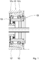
- Bearing arrangement 101 shown comprises two tapered roller bearings 101a, 101b in an O arrangement.
- An output shaft 103 of a wind power transmission is rotatably mounted in a housing insert 105 by means of the bearing arrangement 101 .
- the housing insert 105 is screwed to the wall of a gear housing 107 . By loosening this screw connection, the housing insert 105 can be removed together with the bearing arrangement 101 and the output shaft 103 for maintenance purposes.
- the output shaft 103 forms a screw flange 109 for receiving a generator rotor.
- the generator rotor In order to be able to remove the housing insert 105 with the bearing arrangement 101 and the output shaft 103, the generator rotor must be brought into a maintenance position. For this it is necessary to twist the generator rotor in a suitable way.
- an in 2 illustrated mounting bearing 201 is provided.
- the assembly bearing 201 has an inner ring 203 and an outer ring 205 .
- the outer ring 205 is joined to the output shaft 103 designed as a hollow shaft, the inner ring 205 to the in 2 illustrated generator rotor 207.
- the generator rotor 207 By loosening the screw connection between the generator rotor 207 and the output shaft 103, the generator rotor 207 can be moved relative to the output shaft 103 twist.
- the generator rotor 207 is supported in the output shaft 103 via the assembly bearing 201 .
- the inner ring 203 and the outer ring 205 are axially displaceable relative to one another.
- the generator rotor 205 is also axially displaceable relative to the output shaft 103 .
- the generator rotor 207 can be rotated freely during assembly.
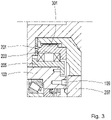
- FIG. 3 shows a spline 301.
- the spline 301 connects the inner ring 203 of the bearing arrangement 201 to the generator rotor 207.
- the generator rotor 207 can be moved axially in the spline 301 relative to the inner ring 203.
Landscapes
- Engineering & Computer Science (AREA)
- General Engineering & Computer Science (AREA)
- Mechanical Engineering (AREA)
- Life Sciences & Earth Sciences (AREA)
- Sustainable Energy (AREA)
- Sustainable Development (AREA)
- Power Engineering (AREA)
- Chemical & Material Sciences (AREA)
- Combustion & Propulsion (AREA)
- Connection Of Motors, Electrical Generators, Mechanical Devices, And The Like (AREA)
- Wind Motors (AREA)
Abstract
Description
- Die Erfindung betrifft eine Anordnung nach dem Oberbegriff von Anspruch 1, ein Verfahren nach Anspruch 11 und ein Verfahren nach Anspruch 13.
- Aus dem Stand der Technik sind Windkraftanlagen bekannt, bei denen das Getriebe und der Generator baulich integriert sind. Eine solche Windkraftanlage offenbart etwa
EP 2 385 247 B1 . Windkraftanlagen mit baulicher Integration von Getriebe und Generator zeichnen sich dadurch aus, dass ein Generatorrotor sich auf eine Ausgangswelle des Getriebes stützt und sich mit der Ausgangswelle des Getriebes ein oder mehrere gemeinsame Lager teilen. - Um bei einer Windkraftanlage mit baulicher Integration von Getriebe und Generator im Wartungsfall das Getriebe zugänglich zu machen, muss der Generator von der Ausgangswelle entkoppelt werden. Dazu werden der Generatorrotor und ein Windrotor gehäusefest fixiert. Um entsprechende Fixiermittel anbringen zu können, müssen der Generatorrotor und der Windrotor jeweils ein eine definierte Winkellage gebracht werden.
- Der Erfindung liegt die Aufgabe zugrunde, die Wartung des Antriebsstrangs einer Windkraftanlage zu vereinfachen. Diese Aufgabe wird gelöst durch eine Anordnung nach Anspruch 1, ein Verfahren nach Anspruch 11 und ein Verfahren nach Anspruch 13. Bevorzugte Weiterbildungen sind in den Unteransprüchen enthalten und ergeben sich aus nachfolgender Beschreibung.
- Die erfindungsgemäße Anordnung umfasst ein Getriebe und einen Generator. Insbesondere kann die Anordnung Teil des Antriebsstrangs einer Windkraftanlage sein. In dem Fall ist ein Windrotor, das heißt ein im Wind stehender und vom Wind angetriebener Rotor, drehfest mit einer Eingangswelle des Getriebes verbunden.
- Ein Generatorrotor, das heißt ein Rotor des Generators, ist drehfest mit einer Ausgangswelle des Getriebes verbunden oder verbindbar. Dies impliziert, dass sowohl die Ausgangswelle als auch der Generatorrotor drehbar gelagert sind. Durch die drehfeste Verbindung des Generatorrotors und der Ausgangswelle ist aber keine Verdrehung des Generatorrotors und der Ausgangswelle relativ zueinander möglich. An der Ausgangswelle anliegende mechanische Leistung wird somit auf den Generatorrotor übertragen und von dem Generator in elektrische Leistung umgewandelt.
- Erfindungsgemäß weist die Anordnung ein Montagelager, das heißt ein Lager, das der Montage der Anordnung und/oder des obengenannten Antriebsstrangs dient, auf. Mit dem Montagelager ist der Generatorrotor in der Ausgangswelle gelagert. Dies bedeutet, dass der Generatorrotor mittels des Montagelagers drehbar in der Ausgangswelle gelagert ist, wenn der Generatorrotor nicht drehfest mit der Ausgangswelle verbunden ist.
- Das Montagelager weist einen ersten Laufring und einen zweiten Laufring auf. Der erste Laufring und der zweite Laufring korrespondieren miteinander. Dies bedeutet, dass der erste Laufring und der zweite Laufring relativ zueinander verdrehbar sind und sich gegeneinander abstützen. Der erste Laufring und der zweite Laufring bilden jeweils mindestens eine Lauffläche aus. Zwischen der Lauffläche des ersten Laufrings und der Lauffläche des zweiten Laufrings verläuft ein Lagerspalt. Handelt es sich um ein Wälzlager, befinden in dem Lagerspalt Wälzkörper, die an der Lauffläche des ersten Laufrings und der Lauffläche des zweiten Laufrings abrollen. Bei einem Gleitlager ist der Lagerspalt mit Schmierstoff und/oder Luft gefüllt. Die Laufflächen des ersten Laufrings und des zweiten Laufrings stützen sich über die Wälzkörper, über den Schmierstoff oder direkt gegeneinander ab.
- Der erste Laufring ist mit der Ausgangswelle, der zweite Laufring mit dem Rotor gefügt. Der erste Laufring und die Ausgangswelle können dabei als separate Stücke ausgeführt oder einstückig miteinander verbunden sein. Entsprechend können der zweite Laufring und der Rotor als separate Stücke ausgeführt oder einstückig miteinander verbunden sein.
- Durch die erfindungsgemäße Lagerung des Generatorrotors in der Ausgangswelle lässt sich der Generatorrotor im Wartungsfall relativ zu der Ausgangswelle verdrehen, um den Generatorrotor in einer Wartungsposition, das heißt in einer bestimmten Drehwinkelstellung fixieren zu können. Die drehfeste Verbindung des Generatorrotors mit der Ausgangswelle muss dazu gelöst sein.
- Im Betrieb ist der Generatorrotor drehfest mit der Ausgangswelle verbunden. Um eine in Betrieb genommene Windkraftanlage mit der erfindungsgemäßen Anordnung warten zu können, ist der Generatorrotor in einer bevorzugten Weiterbildung lösbar mit der Ausgangswelle verbunden. Die drehfeste Verbindung des Generatorrotors mit der Ausgangswelle ist also lösbar weitergebildet. Im Wartungsfall lässt sich dann der Generatorrotor von der Ausgangswelle lösen und mittels des erfindungsgemäßen Montagelagers relativ zu der Ausgangswelle verdrehen, um ihn in die Wartungsposition zu bringen.
- Bevorzugt ist die Ausgangswelle mit einem ersten Schraubflansch weitergebildet. Der Generatorrotor weist weiterbildungsgemäß einen zweiten Schraubflansch auf. Der erste Schraubflansch und der zweite Schraubflansch sind miteinander verschraubbar. Dadurch entsteht die oben beschriebene drehfeste Verbindung zwischen dem Generatorrotor und der Ausgangswelle. Durch die Schraubflansche ist diese Verbindung auf einfache Weise lösbar.
- Um den Generatorrotor im Wartungsfall frei gegenüber der Ausgangswelle verdrehen zu können, ist dieser in einer bevorzugten Weiterbildung axial verschiebbar in der Ausgangswelle gelagert. Insbesondere kann der Generatorrotor axial verschiebbar sein, wenn die drehfeste Verbindung zwischen dem Generatorrotor und der Ausgangswelle gelöst ist. Mit axialer Verschiebbarkeit wird eine Verschiebbarkeit parallel zu einer Drehachse des Generatorrotors, der Ausgangswelle und des Montagelagers bezeichnet.
- Die axial verschiebbare Lagerung des Generatorrotors in der Ausgangswelle lässt sich auf verschiedene Weise realisieren. So ist es etwa möglich, das Montagelager axial verschiebbar weiterzubilden. In dem Fall sind mindestens zwei zueinander korrespondierende Laufringe des Montagelagers axial gegeneinander verschiebbar.
- Bei den korrespondierenden Laufringen handelt es sich etwa um einen inneren Laufring und einen äußeren Laufring des Montagelagers. Der innere Laufring ist mindestens teilweise radial innerhalb des äußeren Laufrings angeordnet. Dies impliziert, dass der äußere Laufring mindestens teilweise radial außerhalb des inneren Laufrings angeordnet ist. Mindestens eine radial, das heißt orthogonal zu der oben genannten Drehachse verlaufende Ebene schneidet sowohl den inneren Laufring als auch den äußeren Laufring.
- Auch lässt sich die axial verschiebbare Lagerung des Generatorrotors in der Ausgangswelle mittels einer Passverzahnung realisieren. Über diese ist mindestens ein Laufring des Montagelagers mit dem Generatorrotor oder der Ausgangswelle verbunden. Die Passverzahnung besteht aus zwei Einzelverzahnungen, die drehfest ineinandergreifen. In axialer Richtung sind die Verzahnungen relativ zueinander verschiebbar. Eine der Verzahnungen ist vorliegend ein- oder mehrstückig mit dem mindestens einen Laufring des Montagelagers gefügt. Die andere Verzahnung ist ein- oder mehrstückig mit dem Generatorrotor oder der Ausgangswelle gefügt.
- Der Generator und das Getriebe sind bevorzugt mindestens teilweise integriert weitergebildet. Dies bedeutet, dass die Ausgangswelle und/oder ein Lager der Ausgangswelle die Gewichtskraft des Generatorrotors mindestens teilweise abstützt. Bei dem Lager der Ausgangswelle handelt es sich um ein Lager, mit dem die Ausgangswelle in einem Gehäuse des Getriebes oder in einem gehäusefest fixierten Bauteil gelagert ist.
- Vorzugsweise sind das Getriebe und der Generator vollständig integriert. In dem Fall weist der Generatorrotor kein eigenes Lager auf, sodass die Ausgangswelle und/oder das mindestens eine Lager der Ausgangswelle die Gewichtskraft des Generatorrotors vollständig abstützen.
- Bevorzugt ist der Generatorrotor mit einer Montagesicherung weitergebildet. Dies ist ein Mittel, mit dem der Generatorrotor gehäusefest fixierbar ist. Der Generatorrotor ist also mittels der Montagesicherung in einem Gehäuse des Getriebes oder des Generators oder in einem gehäusefesten Bauteil, das heißt in einem Bauteil, das in dem Gehäuse des Getriebes oder des Generators starr fixiert ist, fixierbar. Die Montagesicherung kommt zur Anwendung, wenn das Getriebe und der Generator teilweise oder vollständig integriert sind. Da die Gewichtskraft des Generatorrotors dann mindestens teilweise von der Ausgangswelle und/oder dem mindestens einen Lager der Ausgangswelle abgestützt wird, ist die Montagesicherung erforderlich, um die Ausgangswelle und/oder das mindestens eine Lager der Ausgangswelle demontieren zu können.
- In einer bevorzugten Weiterbildung umfasst die Anordnung den eingangs erwähnten Windrotor.
- Bevorzugt ist die Anordnung darüber hinaus mit einer Montagesicherung für den Windrotor weitergebildet. Diese dient dazu, den Windrotor gehäusefest zu fixieren. Der Windrotor ist also mittels der Montagesicherung in dem Gehäuse des Getriebes oder in einem gehäusefesten Bauteil, das starr in dem Gehäuse des Getriebes fixiert ist, fixierbar.
- Ein erfindungsgemäßes Verfahren dient der Inbetriebsetzung einer mit einer Montagesicherung für den Generatorrotor weitergebildeten Anordnung. Zunächst ist der Generatorrotor mittels der Montagesicherung gehäusefest fixiert. Mittels einer weiteren Montagesicherung kann darüber hinaus auch der Windrotor gehäusefest fixiert sein.
- Zur Inbetriebnahme wird die Montagesicherung des Generatorrotors gelöst. Das Montagelager erlaubt es, den Generatorrotor dann relativ zu der Ausgangswelle zu drehen. Durch Verdrehung relativ zu der Ausgangswelle wird der Generatorrotor in eine Drehwinkellage gebracht, in der er sich drehfest mit der Ausgangswelle verbinden lässt. Sind etwa die Ausgangswelle und der Generatorrotor mit Schraubflanschen weitergebildet, wird der Generatorrotor so verdreht, dass die Schraublöcher der beiden Schraubflansche zueinander fluchten und die Schrauben eingesteckt werden können.
- Falls vorhanden, wird auch die Montagesicherung des Windrotors wieder gelöst. Dies geschieht bevorzugt, nachdem der Generatorrotor drehfest mit der Ausgangswelle verbunden wurde.
- Da das Montagelager im Betrieb nicht gebraucht wird und funktionslos ist, wird es in einer bevorzugten Weiterbildung des Verfahrens ausgebaut. Das Montagelager wird also weiterbildungsgemäß aus der Anordnung entfernt. Dies geschieht bevorzugt, nachdem der Generatorrotor drehfest mit der Ausgangswelle verbunden wurde.
- Ein weiteres erfindungsgemäßes Verfahren dient der Wartung der mit der Montagesicherung für den Generator weitergebildeten Anordnung. Das Verfahren sieht vor, die Anordnung durch Lösen der drehfesten Verbindung des Generatorrotors mit der Ausgangswelle außer Betrieb zu setzen und den Generatorrotor relativ zu der Ausgangswelle in eine Wartungsposition zu verdrehen. Befindet sich der Generatorrotor in der Wartungsposition, wird er mittels der Montagesicherung gehäusefest fixiert. Dies geschieht bevorzugt, bevor die drehfeste Verbindung des Generatorrotors mit der Ausgangswelle gelöst wird.
- Eine bevorzugte Weiterbildung des Verfahrens sieht vor, dass das Montagelager in die Anordnung eingebaut wird - bevorzugt vor dem Lösen der drehfesten Verbindung des Generatorrotors mit der Ausgangswelle.
- In bevorzugten Weiterbildungen jeweils eines der beiden erfindungsgemäßen Verfahren wird der Generatorrotor axial verschoben. Im Einzelnen wird er axial von der Ausgangswelle weg verschoben, wenn er von der Betriebsposition aus in die Wartungsposition gebracht werden soll. Dies geschieht, nachdem die drehfeste Verbindung des Generatorrotors mit der Ausgangswelle gelöst wurde.
- Soll der Generatorrotor umgekehrt von der Wartungsposition in die Betriebsposition gebracht werden, wird er axial in Richtung der Ausgangswelle verschoben. Dies geschieht, bevor der Generatorrotor drehfest mit der Ausgangswelle verbunden wird.
- Bevorzugte Ausführungsbeispiele der Erfindung sind in den Figuren dargestellt. Übereinstimmende Bezugsziffern kennzeichnen dabei gleiche oder funktionsgleiche Merkmale.
- Im Einzelnen zeigt:
-
Fig. 1 eine Lageranordnung für einen integrierten Generatorrotor; -
Fig. 2 ein Montagelager; und -
Fig. 3 ein Montagelager mit Passverzahnung. - Die in
Fig. 1 dargestellte Lageranordnung 101 umfasst zwei Kegelrollenlager 101a, 101b in O-Anordnung. Mittels der Lageranordnung 101 ist eine Ausgangswelle 103 eines Windkraftgetriebes drehbar in einem Gehäuseeinsatz 105 gelagert. - Der Gehäuseeinsatz 105 ist mit der Wandung eines Getriebegehäuses 107 verschraubt. Durch Lösen dieser Verschraubung lässt sich der Gehäuseeinsatz 105 zusammen mit der Lageranordnung 101 und der Ausgangswelle 103 zu Wartungszwecken entnehmen.
- Die Ausgangswelle 103 bildet einen Schraubflansch 109 zur Aufnahme eines Generatorrotors aus. Um den Gehäuseeinsatz 105 mit der Lageranordnung 101 und der Ausgangswelle 103 entnehmen zu können, muss der Generatorrotor in eine Wartungsposition gebracht werden. Dazu ist es erforderlich, den Generatorrotor geeignet zu verdrehen.
- Um den Generatorrotor unabhängig von der Ausgangswelle 103 verdrehen zu können, ist ein in
Fig. 2 dargestelltes Montagelager 201 vorgesehen. Das Montagelager 201 weist einen Innenring 203 und einen Außenring 205 auf. Der Außenring 205 ist mit der als Hohlwelle ausgestalteten Ausgangswelle 103 gefügt, der Innenring 205 mit dem inFig. 2 dargestellten Generatorrotor 207. - Indem die Verschraubung zwischen dem Generatorrotor 207 und der Ausgangswelle 103 gelöst wird, lässt sich der Generatorrotor 207 relativ zu der Ausgangswelle 103 verdrehen. Dabei stützt sich der Generatorrotor 207 über das Montagelager 201 in der Ausgangswelle 103 ab.
- Der Innenring 203 und der Außenring 205 sind relativ zueinander axial verschiebbar. Infolgedessen ist auch der Generatorrotor 205 relativ zu der Ausgangswelle 103 axial verschiebbar. Dadurch ist der Generatorrotor 207 im Montagefall frei verdrehbar.
- In
Fig. 3 zeigt eine Passverzahnung 301. Die Passverzahnung 301 verbindet den Innenring 203 der Lageranordnung 201 mit dem Generatorrotor 207. Dadurch lässt sich der Generatorrotor 207 in der Passverzahnung 301 relativ zu dem Innenring 203 axial verschieben. -
- 101
- Lageranordnung
- 101a
- Kegelrollenlager
- 101b
- Kegelrollenlager
- 103
- Ausgangswelle
- 105
- Gehäuseeinsatz
- 107
- Getriebegehäuse
- 109
- Schraubflansch
- 201
- Montagelager
- 203
- Innenring
- 205
- Außenring
- 207
- Generatorrotor
- 301
- Passverzahnung
Claims (15)
- Anordnung mit einem Getriebe und einem Generator; wobeiein Generatorrotor (207) drehfest mit einer Ausgangswelle (103) des Getriebes verbunden oder verbindbar ist; gekennzeichnet durchein Montagelager (201), mit dem der Generatorrotor (207) in der Ausgangswelle (103) gelagert ist.
- Anordnung nach einem der vorhergehenden Ansprüche; dadurch gekennzeichnet, dass
der Generatorrotor (207) lösbar mit der Ausgangswelle (103) verbunden ist. - Anordnung nach dem vorhergehenden Anspruch; dadurch gekennzeichnet, dass die Ausgangswelle (103) einen ersten Schraubflansch (109) und der Generatorrotor (207) einen zweiten, mit dem ersten Schraubflansch (109) verschraubten Schraubflansch aufweist.
- Anordnung nach einem der vorhergehenden Ansprüche; dadurch gekennzeichnet, dass
der Generatorrotor (027) axial verschiebbar in der Ausgangswelle (103) gelagert ist. - Anordnung nach dem vorhergehenden Anspruch; dadurch gekennzeichnet, dass mindestens zwei korrespondierende Laufringe des Montagelager (201) axial gegeneinander verschiebbar sind.
- Anordnung nach dem vorhergehenden Anspruch; gekennzeichnet, durch eine Passverzahnung (301); wobei
mindestens ein Laufring des Montagelagers (201) über die Passverzahnung (301) mit dem Generatorrotor (207) oder der Ausgangswelle (103) verbunden ist. - Anordnung nach einem der vorhergehenden Ansprüche; dadurch gekennzeichnet, dass
die Ausgangswelle (103) und/oder mindestens ein Lager (101) der Ausgangswelle (103) die Gewichtskraft des Generatorrotors (207) mindestens teilweise abstützt. - Anordnung nach einem der vorhergehenden Ansprüche; gekennzeichnet durch eine Montagesicherung für den Generatorrotor (207); wobei
der Generatorrotor (207) mittels der Montagesicherung gehäusefest fixierbar ist. - Anordnung nach einem der vorhergehenden Ansprüche; gekennzeichnet durch einen Windrotor, der drehfest mit einer Eingangswelle des Getriebes verbunden ist.
- Anordnung nach dem vorhergehenden Anspruch; gekennzeichnet durch eine Montagesicherung für den Windrotor; wobei
der Windrotor mittels der Montagesicherung gehäusefest fixierbar ist. - Verfahren zur Montage einer Anordnung nach einem der Ansprüche 8 bis 10; mit den Schritten- lösen der Montagesicherung des Generatorrotors (207),- drehen des Generatorrotors (207) relativ zu der Ausgangswelle (103), und- verbinden des Generatorrotors (207) drehfest mit der Ausgangswelle (103).
- Verfahren nach dem vorhergehenden Anspruch; mit dem Schritt- ausbauen des Montagelagers (201).
- Verfahren zur Demontage einer Anordnung nach einem der Ansprüche 8 bis 10; mit den Schritten- lösen der drehfesten Verbindung des Generatorrotors (207) mit der Ausgangswelle (103);- drehen des Generatorrotors (207) relativ zu der Ausgangswelle (103), und- fixieren des Generatorrotors (207) mittels der Montagesicherung gehäusefest.
- Verfahren nach dem vorhergehenden Anspruch; mit dem Schritt- einbauen des Montagelagers (201).
- Verfahren nach einem der vorhergehenden zwei Ansprüche zur Demontage einer Anordnung nach Anspruch 4; mit dem Schritt- verschieben des Generatorrotors (207) axial.
Applications Claiming Priority (1)
| Application Number | Priority Date | Filing Date | Title |
|---|---|---|---|
| DE102021207462.6A DE102021207462B3 (de) | 2021-07-14 | 2021-07-14 | Rotatorische Entkopplung zur Montage und Demontage eines getriebeintegriert gelagerten Generatorrotors |
Publications (2)
| Publication Number | Publication Date |
|---|---|
| EP4120521A1 true EP4120521A1 (de) | 2023-01-18 |
| EP4120521B1 EP4120521B1 (de) | 2025-12-03 |
Family
ID=82020941
Family Applications (1)
| Application Number | Title | Priority Date | Filing Date |
|---|---|---|---|
| EP22178557.9A Active EP4120521B1 (de) | 2021-07-14 | 2022-06-13 | Rotatorische entkopplung zur montage und demontage eines getriebeintegriert gelagerten generatorrotors |
Country Status (5)
| Country | Link |
|---|---|
| US (1) | US12146468B2 (de) |
| EP (1) | EP4120521B1 (de) |
| CN (1) | CN115614234A (de) |
| DE (1) | DE102021207462B3 (de) |
| ES (1) | ES3063587T3 (de) |
Families Citing this family (1)
| Publication number | Priority date | Publication date | Assignee | Title |
|---|---|---|---|---|
| DE102018218976A1 (de) * | 2018-11-07 | 2020-05-07 | Zf Friedrichshafen Ag | Schmierstofftransferring mit mehreren Kammern |
Citations (4)
| Publication number | Priority date | Publication date | Assignee | Title |
|---|---|---|---|---|
| DE10311917A1 (de) * | 2003-03-17 | 2004-10-07 | Centa-Antriebe Kirschey Gmbh | Kupplung zur reibschlüssigen Drehverbindung von Maschinenteilen |
| US20140125064A1 (en) * | 2011-02-04 | 2014-05-08 | Georg Hofmann | Rotor bearing for an electrical machine |
| US20160091029A1 (en) * | 2014-09-26 | 2016-03-31 | Siemens Aktiengesellschaft | Overload coupling |
| EP2385247B1 (de) | 2010-05-06 | 2019-03-27 | The Switch Drive Systems Oy | Elektromechanische Vorrichtung |
Family Cites Families (1)
| Publication number | Priority date | Publication date | Assignee | Title |
|---|---|---|---|---|
| US11486368B2 (en) * | 2018-08-31 | 2022-11-01 | Vestas Wind Systems A/S | Tool chain and method for concentric fixing and exchange of gearbox and generator internal components |
-
2021
- 2021-07-14 DE DE102021207462.6A patent/DE102021207462B3/de active Active
-
2022
- 2022-06-13 ES ES22178557T patent/ES3063587T3/es active Active
- 2022-06-13 EP EP22178557.9A patent/EP4120521B1/de active Active
- 2022-06-22 CN CN202210709145.3A patent/CN115614234A/zh active Pending
- 2022-07-01 US US17/810,350 patent/US12146468B2/en active Active
Patent Citations (4)
| Publication number | Priority date | Publication date | Assignee | Title |
|---|---|---|---|---|
| DE10311917A1 (de) * | 2003-03-17 | 2004-10-07 | Centa-Antriebe Kirschey Gmbh | Kupplung zur reibschlüssigen Drehverbindung von Maschinenteilen |
| EP2385247B1 (de) | 2010-05-06 | 2019-03-27 | The Switch Drive Systems Oy | Elektromechanische Vorrichtung |
| US20140125064A1 (en) * | 2011-02-04 | 2014-05-08 | Georg Hofmann | Rotor bearing for an electrical machine |
| US20160091029A1 (en) * | 2014-09-26 | 2016-03-31 | Siemens Aktiengesellschaft | Overload coupling |
Also Published As
| Publication number | Publication date |
|---|---|
| EP4120521B1 (de) | 2025-12-03 |
| CN115614234A (zh) | 2023-01-17 |
| ES3063587T3 (en) | 2026-04-17 |
| US20230014947A1 (en) | 2023-01-19 |
| US12146468B2 (en) | 2024-11-19 |
| DE102021207462B3 (de) | 2022-07-14 |
Similar Documents
| Publication | Publication Date | Title |
|---|---|---|
| EP2205863B2 (de) | Lageranordnung einer rotornabe einer windenergieanlage und verfahren zu deren montage | |
| DE102022201821B4 (de) | Getriebe für ein elektrisches Antriebssystem eines Kraftfahrzeugs sowie elektrisches Antriebssystem mit einem solchen Getriebe | |
| EP1867871A2 (de) | Windenergieanlage mit einem Rotor | |
| DE102021213012B3 (de) | Differential mit geteiltem Gehäuse und variabler Zahl an Planetenrädern sowie Montageverfahren | |
| DE102014201465A1 (de) | Modulare Kopplung eines Windkraftgetriebes mit einem Generator | |
| DE102021207462B3 (de) | Rotatorische Entkopplung zur Montage und Demontage eines getriebeintegriert gelagerten Generatorrotors | |
| DE10017548B4 (de) | Generatorgetriebe | |
| WO2020099044A1 (de) | Lagerkassette für windkraftanlagen | |
| EP3650689A1 (de) | Ausgangsmodul mit integriertem lagerring | |
| EP4689444A1 (de) | Planetengetriebe mit in planetenträger gelagertem sonnenrad | |
| WO2024223554A1 (de) | Planetengetriebe mit welle-nabe-verbindung | |
| EP3791080A1 (de) | Getriebeanordnung sowie verfahren zur herstellung einer getriebeanordnung | |
| DE102021214132B4 (de) | Getriebe und Generator mit Zwischenwelle | |
| DE3614803A1 (de) | Getriebe zum antrieb der walzen einer walzstrasse | |
| DE102025101431B3 (de) | Lagerung eines Stirnrads auf einem Planetenträger | |
| WO2022069736A1 (de) | Verfahren zur gebrauchsdauerverlängerung einer hauptlagerungsanordnung einer windkraftanlage | |
| EP4388226B1 (de) | Transportsicherung mit montagelager | |
| DE102014226046A1 (de) | Wolfrom-Getriebe mit dreifach verzahnten Planeten | |
| DE102023200204B4 (de) | Lenklageranordnung eines Radantriebes für ein Fahrzeug sowie Verfahren zur Montage einer Lenkanordnung | |
| DE102023207666A1 (de) | Gefaltete Sonnenwelle mit Dichtungsanordnung | |
| DE102010051209A1 (de) | Rotorlager einer Windkraftanlage | |
| EP3587809B1 (de) | Triebstranganordnung für eine windenergieanlage | |
| EP4491908A1 (de) | Lageranordnung, insbesondere für windkraftanlagen | |
| EP4729767A1 (de) | Komponentenschnittstelle zwischen getriebeeinheit und generatoreinheit | |
| DE102006060389A1 (de) | Getriebeeinheit mit integrierter Ausgleichskupplung |
Legal Events
| Date | Code | Title | Description |
|---|---|---|---|
| PUAI | Public reference made under article 153(3) epc to a published international application that has entered the european phase |
Free format text: ORIGINAL CODE: 0009012 |
|
| STAA | Information on the status of an ep patent application or granted ep patent |
Free format text: STATUS: THE APPLICATION HAS BEEN PUBLISHED |
|
| AK | Designated contracting states |
Kind code of ref document: A1 Designated state(s): AL AT BE BG CH CY CZ DE DK EE ES FI FR GB GR HR HU IE IS IT LI LT LU LV MC MK MT NL NO PL PT RO RS SE SI SK SM TR |
|
| STAA | Information on the status of an ep patent application or granted ep patent |
Free format text: STATUS: REQUEST FOR EXAMINATION WAS MADE |
|
| 17P | Request for examination filed |
Effective date: 20230714 |
|
| RBV | Designated contracting states (corrected) |
Designated state(s): AL AT BE BG CH CY CZ DE DK EE ES FI FR GB GR HR HU IE IS IT LI LT LU LV MC MK MT NL NO PL PT RO RS SE SI SK SM TR |
|
| STAA | Information on the status of an ep patent application or granted ep patent |
Free format text: STATUS: EXAMINATION IS IN PROGRESS |
|
| 17Q | First examination report despatched |
Effective date: 20240228 |
|
| GRAP | Despatch of communication of intention to grant a patent |
Free format text: ORIGINAL CODE: EPIDOSNIGR1 |
|
| STAA | Information on the status of an ep patent application or granted ep patent |
Free format text: STATUS: GRANT OF PATENT IS INTENDED |
|
| RIC1 | Information provided on ipc code assigned before grant |
Ipc: H02K 7/18 20060101AFI20250702BHEP Ipc: F16C 39/02 20060101ALI20250702BHEP Ipc: H02K 7/116 20060101ALI20250702BHEP Ipc: H02K 7/08 20060101ALI20250702BHEP Ipc: F16H 57/023 20120101ALI20250702BHEP Ipc: F16H 57/021 20120101ALI20250702BHEP Ipc: F03D 15/00 20160101ALI20250702BHEP Ipc: F03D 80/70 20160101ALI20250702BHEP Ipc: F16C 35/073 20060101ALI20250702BHEP Ipc: F16C 35/077 20060101ALI20250702BHEP Ipc: H02K 7/00 20060101ALI20250702BHEP Ipc: F16H 57/02 20120101ALN20250702BHEP |
|
| INTG | Intention to grant announced |
Effective date: 20250724 |
|
| GRAS | Grant fee paid |
Free format text: ORIGINAL CODE: EPIDOSNIGR3 |
|
| GRAA | (expected) grant |
Free format text: ORIGINAL CODE: 0009210 |
|
| STAA | Information on the status of an ep patent application or granted ep patent |
Free format text: STATUS: THE PATENT HAS BEEN GRANTED |
|
| AK | Designated contracting states |
Kind code of ref document: B1 Designated state(s): AL AT BE BG CH CY CZ DE DK EE ES FI FR GB GR HR HU IE IS IT LI LT LU LV MC MK MT NL NO PL PT RO RS SE SI SK SM TR |
|
| REG | Reference to a national code |
Ref country code: CH Ref legal event code: F10 Free format text: ST27 STATUS EVENT CODE: U-0-0-F10-F00 (AS PROVIDED BY THE NATIONAL OFFICE) Effective date: 20251203 Ref country code: GB Ref legal event code: FG4D Free format text: NOT ENGLISH |
|
| REG | Reference to a national code |
Ref country code: DE Ref legal event code: R096 Ref document number: 502022006279 Country of ref document: DE |
|
| REG | Reference to a national code |
Ref country code: IE Ref legal event code: FG4D Free format text: LANGUAGE OF EP DOCUMENT: GERMAN |
|
| REG | Reference to a national code |
Ref country code: NL Ref legal event code: MP Effective date: 20251203 |
|
| REG | Reference to a national code |
Ref country code: LT Ref legal event code: MG9D |
|
| PG25 | Lapsed in a contracting state [announced via postgrant information from national office to epo] |
Ref country code: NO Free format text: LAPSE BECAUSE OF FAILURE TO SUBMIT A TRANSLATION OF THE DESCRIPTION OR TO PAY THE FEE WITHIN THE PRESCRIBED TIME-LIMIT Effective date: 20260303 |
|
| PG25 | Lapsed in a contracting state [announced via postgrant information from national office to epo] |
Ref country code: FI Free format text: LAPSE BECAUSE OF FAILURE TO SUBMIT A TRANSLATION OF THE DESCRIPTION OR TO PAY THE FEE WITHIN THE PRESCRIBED TIME-LIMIT Effective date: 20251203 Ref country code: HR Free format text: LAPSE BECAUSE OF FAILURE TO SUBMIT A TRANSLATION OF THE DESCRIPTION OR TO PAY THE FEE WITHIN THE PRESCRIBED TIME-LIMIT Effective date: 20251203 |
|
| PG25 | Lapsed in a contracting state [announced via postgrant information from national office to epo] |
Ref country code: RS Free format text: LAPSE BECAUSE OF FAILURE TO SUBMIT A TRANSLATION OF THE DESCRIPTION OR TO PAY THE FEE WITHIN THE PRESCRIBED TIME-LIMIT Effective date: 20260303 |
|
| REG | Reference to a national code |
Ref country code: ES Ref legal event code: FG2A Ref document number: 3063587 Country of ref document: ES Kind code of ref document: T3 Effective date: 20260417 |
|
| PG25 | Lapsed in a contracting state [announced via postgrant information from national office to epo] |
Ref country code: PL Free format text: LAPSE BECAUSE OF FAILURE TO SUBMIT A TRANSLATION OF THE DESCRIPTION OR TO PAY THE FEE WITHIN THE PRESCRIBED TIME-LIMIT Effective date: 20251203 |
|
| PG25 | Lapsed in a contracting state [announced via postgrant information from national office to epo] |
Ref country code: LV Free format text: LAPSE BECAUSE OF FAILURE TO SUBMIT A TRANSLATION OF THE DESCRIPTION OR TO PAY THE FEE WITHIN THE PRESCRIBED TIME-LIMIT Effective date: 20251203 |
|
| PG25 | Lapsed in a contracting state [announced via postgrant information from national office to epo] |
Ref country code: BG Free format text: LAPSE BECAUSE OF FAILURE TO SUBMIT A TRANSLATION OF THE DESCRIPTION OR TO PAY THE FEE WITHIN THE PRESCRIBED TIME-LIMIT Effective date: 20251203 |
|
| PG25 | Lapsed in a contracting state [announced via postgrant information from national office to epo] |
Ref country code: NL Free format text: LAPSE BECAUSE OF FAILURE TO SUBMIT A TRANSLATION OF THE DESCRIPTION OR TO PAY THE FEE WITHIN THE PRESCRIBED TIME-LIMIT Effective date: 20251203 |
|
| PG25 | Lapsed in a contracting state [announced via postgrant information from national office to epo] |
Ref country code: LT Free format text: LAPSE BECAUSE OF FAILURE TO SUBMIT A TRANSLATION OF THE DESCRIPTION OR TO PAY THE FEE WITHIN THE PRESCRIBED TIME-LIMIT Effective date: 20251203 |
|
| PG25 | Lapsed in a contracting state [announced via postgrant information from national office to epo] |
Ref country code: SM Free format text: LAPSE BECAUSE OF FAILURE TO SUBMIT A TRANSLATION OF THE DESCRIPTION OR TO PAY THE FEE WITHIN THE PRESCRIBED TIME-LIMIT Effective date: 20251203 |
|
| PG25 | Lapsed in a contracting state [announced via postgrant information from national office to epo] |
Ref country code: IT Free format text: LAPSE BECAUSE OF FAILURE TO SUBMIT A TRANSLATION OF THE DESCRIPTION OR TO PAY THE FEE WITHIN THE PRESCRIBED TIME-LIMIT Effective date: 20251203 |
|
| PGFP | Annual fee paid to national office [announced via postgrant information from national office to epo] |
Ref country code: AT Payment date: 20260714 Year of fee payment: 5 |
|
| PG25 | Lapsed in a contracting state [announced via postgrant information from national office to epo] |
Ref country code: EE Free format text: LAPSE BECAUSE OF FAILURE TO SUBMIT A TRANSLATION OF THE DESCRIPTION OR TO PAY THE FEE WITHIN THE PRESCRIBED TIME-LIMIT Effective date: 20251203 |
|
| PG25 | Lapsed in a contracting state [announced via postgrant information from national office to epo] |
Ref country code: PT Free format text: LAPSE BECAUSE OF FAILURE TO SUBMIT A TRANSLATION OF THE DESCRIPTION OR TO PAY THE FEE WITHIN THE PRESCRIBED TIME-LIMIT Effective date: 20260406 Ref country code: IS Free format text: LAPSE BECAUSE OF FAILURE TO SUBMIT A TRANSLATION OF THE DESCRIPTION OR TO PAY THE FEE WITHIN THE PRESCRIBED TIME-LIMIT Effective date: 20260403 |
|
| PG25 | Lapsed in a contracting state [announced via postgrant information from national office to epo] |
Ref country code: CZ Free format text: LAPSE BECAUSE OF FAILURE TO SUBMIT A TRANSLATION OF THE DESCRIPTION OR TO PAY THE FEE WITHIN THE PRESCRIBED TIME-LIMIT Effective date: 20251203 |
|
| PG25 | Lapsed in a contracting state [announced via postgrant information from national office to epo] |
Ref country code: SK Free format text: LAPSE BECAUSE OF FAILURE TO SUBMIT A TRANSLATION OF THE DESCRIPTION OR TO PAY THE FEE WITHIN THE PRESCRIBED TIME-LIMIT Effective date: 20251203 |
|
| PG25 | Lapsed in a contracting state [announced via postgrant information from national office to epo] |
Ref country code: SE Free format text: LAPSE BECAUSE OF FAILURE TO SUBMIT A TRANSLATION OF THE DESCRIPTION OR TO PAY THE FEE WITHIN THE PRESCRIBED TIME-LIMIT Effective date: 20251203 |