EP4120384B1 - Method for manufacturing secondary battery and apparatus for manufacturing secondary battery - Google Patents
Method for manufacturing secondary battery and apparatus for manufacturing secondary battery Download PDFInfo
- Publication number
- EP4120384B1 EP4120384B1 EP21813591.1A EP21813591A EP4120384B1 EP 4120384 B1 EP4120384 B1 EP 4120384B1 EP 21813591 A EP21813591 A EP 21813591A EP 4120384 B1 EP4120384 B1 EP 4120384B1
- Authority
- EP
- European Patent Office
- Prior art keywords
- electrode
- notching
- electrode portion
- inspection
- abnormal
- Prior art date
- Legal status (The legal status is an assumption and is not a legal conclusion. Google has not performed a legal analysis and makes no representation as to the accuracy of the status listed.)
- Active
Links
Images

Classifications
-
- B—PERFORMING OPERATIONS; TRANSPORTING
- B26—HAND CUTTING TOOLS; CUTTING; SEVERING
- B26D—CUTTING; DETAILS COMMON TO MACHINES FOR PERFORATING, PUNCHING, CUTTING-OUT, STAMPING-OUT OR SEVERING
- B26D5/00—Arrangements for operating and controlling machines or devices for cutting, cutting-out, stamping-out, punching, perforating, or severing by means other than cutting
- B26D5/20—Arrangements for operating and controlling machines or devices for cutting, cutting-out, stamping-out, punching, perforating, or severing by means other than cutting with interrelated action between the cutting member and work feed
- B26D5/30—Arrangements for operating and controlling machines or devices for cutting, cutting-out, stamping-out, punching, perforating, or severing by means other than cutting with interrelated action between the cutting member and work feed having the cutting member controlled by scanning a record carrier
- B26D5/34—Arrangements for operating and controlling machines or devices for cutting, cutting-out, stamping-out, punching, perforating, or severing by means other than cutting with interrelated action between the cutting member and work feed having the cutting member controlled by scanning a record carrier scanning being effected by a photosensitive device
-
- B—PERFORMING OPERATIONS; TRANSPORTING
- B23—MACHINE TOOLS; METAL-WORKING NOT OTHERWISE PROVIDED FOR
- B23K—SOLDERING OR UNSOLDERING; WELDING; CLADDING OR PLATING BY SOLDERING OR WELDING; CUTTING BY APPLYING HEAT LOCALLY, e.g. FLAME CUTTING; WORKING BY LASER BEAM
- B23K26/00—Working by laser beam, e.g. welding, cutting or boring
- B23K26/02—Positioning or observing the workpiece, e.g. with respect to the point of impact; Aligning, aiming or focusing the laser beam
- B23K26/03—Observing, e.g. monitoring, the workpiece
- B23K26/032—Observing, e.g. monitoring, the workpiece using optical means
-
- B—PERFORMING OPERATIONS; TRANSPORTING
- B23—MACHINE TOOLS; METAL-WORKING NOT OTHERWISE PROVIDED FOR
- B23K—SOLDERING OR UNSOLDERING; WELDING; CLADDING OR PLATING BY SOLDERING OR WELDING; CUTTING BY APPLYING HEAT LOCALLY, e.g. FLAME CUTTING; WORKING BY LASER BEAM
- B23K26/00—Working by laser beam, e.g. welding, cutting or boring
- B23K26/08—Devices involving relative movement between laser beam and workpiece
- B23K26/083—Devices involving movement of the workpiece in at least one axial direction
-
- B—PERFORMING OPERATIONS; TRANSPORTING
- B23—MACHINE TOOLS; METAL-WORKING NOT OTHERWISE PROVIDED FOR
- B23K—SOLDERING OR UNSOLDERING; WELDING; CLADDING OR PLATING BY SOLDERING OR WELDING; CUTTING BY APPLYING HEAT LOCALLY, e.g. FLAME CUTTING; WORKING BY LASER BEAM
- B23K26/00—Working by laser beam, e.g. welding, cutting or boring
- B23K26/36—Removing material
- B23K26/38—Removing material by boring or cutting
-
- B—PERFORMING OPERATIONS; TRANSPORTING
- B26—HAND CUTTING TOOLS; CUTTING; SEVERING
- B26D—CUTTING; DETAILS COMMON TO MACHINES FOR PERFORATING, PUNCHING, CUTTING-OUT, STAMPING-OUT OR SEVERING
- B26D1/00—Cutting through work characterised by the nature or movement of the cutting member or particular materials not otherwise provided for; Apparatus or machines therefor; Cutting members therefor
- B26D1/01—Cutting through work characterised by the nature or movement of the cutting member or particular materials not otherwise provided for; Apparatus or machines therefor; Cutting members therefor involving a cutting member which does not travel with the work
- B26D1/04—Cutting through work characterised by the nature or movement of the cutting member or particular materials not otherwise provided for; Apparatus or machines therefor; Cutting members therefor involving a cutting member which does not travel with the work having a linearly-movable cutting member
- B26D1/06—Cutting through work characterised by the nature or movement of the cutting member or particular materials not otherwise provided for; Apparatus or machines therefor; Cutting members therefor involving a cutting member which does not travel with the work having a linearly-movable cutting member wherein the cutting member reciprocates
- B26D1/065—Cutting through work characterised by the nature or movement of the cutting member or particular materials not otherwise provided for; Apparatus or machines therefor; Cutting members therefor involving a cutting member which does not travel with the work having a linearly-movable cutting member wherein the cutting member reciprocates for thin material, e.g. for sheets, strips or the like
-
- B—PERFORMING OPERATIONS; TRANSPORTING
- B26—HAND CUTTING TOOLS; CUTTING; SEVERING
- B26F—PERFORATING; PUNCHING; CUTTING-OUT; STAMPING-OUT; SEVERING BY MEANS OTHER THAN CUTTING
- B26F1/00—Perforating; Punching; Cutting-out; Stamping-out; Apparatus therefor
- B26F1/02—Perforating by punching, e.g. with relatively-reciprocating punch and bed
- B26F1/12—Perforating by punching, e.g. with relatively-reciprocating punch and bed to notch margins of work
-
- H—ELECTRICITY
- H01—ELECTRIC ELEMENTS
- H01M—PROCESSES OR MEANS, e.g. BATTERIES, FOR THE DIRECT CONVERSION OF CHEMICAL ENERGY INTO ELECTRICAL ENERGY
- H01M10/00—Secondary cells; Manufacture thereof
- H01M10/04—Construction or manufacture in general
-
- H—ELECTRICITY
- H01—ELECTRIC ELEMENTS
- H01M—PROCESSES OR MEANS, e.g. BATTERIES, FOR THE DIRECT CONVERSION OF CHEMICAL ENERGY INTO ELECTRICAL ENERGY
- H01M10/00—Secondary cells; Manufacture thereof
- H01M10/04—Construction or manufacture in general
- H01M10/0404—Machines for assembling batteries
-
- H—ELECTRICITY
- H01—ELECTRIC ELEMENTS
- H01M—PROCESSES OR MEANS, e.g. BATTERIES, FOR THE DIRECT CONVERSION OF CHEMICAL ENERGY INTO ELECTRICAL ENERGY
- H01M10/00—Secondary cells; Manufacture thereof
- H01M10/04—Construction or manufacture in general
- H01M10/0404—Machines for assembling batteries
- H01M10/0409—Machines for assembling batteries for cells with wound electrodes
-
- H—ELECTRICITY
- H01—ELECTRIC ELEMENTS
- H01M—PROCESSES OR MEANS, e.g. BATTERIES, FOR THE DIRECT CONVERSION OF CHEMICAL ENERGY INTO ELECTRICAL ENERGY
- H01M10/00—Secondary cells; Manufacture thereof
- H01M10/42—Methods or arrangements for servicing or maintenance of secondary cells or secondary half-cells
-
- H—ELECTRICITY
- H01—ELECTRIC ELEMENTS
- H01M—PROCESSES OR MEANS, e.g. BATTERIES, FOR THE DIRECT CONVERSION OF CHEMICAL ENERGY INTO ELECTRICAL ENERGY
- H01M4/00—Electrodes
- H01M4/02—Electrodes composed of, or comprising, active material
- H01M4/04—Processes of manufacture in general
-
- H—ELECTRICITY
- H01—ELECTRIC ELEMENTS
- H01M—PROCESSES OR MEANS, e.g. BATTERIES, FOR THE DIRECT CONVERSION OF CHEMICAL ENERGY INTO ELECTRICAL ENERGY
- H01M50/00—Constructional details or processes of manufacture of the non-active parts of electrochemical cells other than fuel cells, e.g. hybrid cells
- H01M50/50—Current conducting connections for cells or batteries
- H01M50/531—Electrode connections inside a battery casing
-
- B—PERFORMING OPERATIONS; TRANSPORTING
- B23—MACHINE TOOLS; METAL-WORKING NOT OTHERWISE PROVIDED FOR
- B23K—SOLDERING OR UNSOLDERING; WELDING; CLADDING OR PLATING BY SOLDERING OR WELDING; CUTTING BY APPLYING HEAT LOCALLY, e.g. FLAME CUTTING; WORKING BY LASER BEAM
- B23K2101/00—Articles made by soldering, welding or cutting
- B23K2101/36—Electric or electronic devices
-
- B—PERFORMING OPERATIONS; TRANSPORTING
- B26—HAND CUTTING TOOLS; CUTTING; SEVERING
- B26D—CUTTING; DETAILS COMMON TO MACHINES FOR PERFORATING, PUNCHING, CUTTING-OUT, STAMPING-OUT OR SEVERING
- B26D1/00—Cutting through work characterised by the nature or movement of the cutting member or particular materials not otherwise provided for; Apparatus or machines therefor; Cutting members therefor
- B26D1/0006—Cutting members therefor
- B26D2001/0066—Cutting members therefor having shearing means, e.g. shearing blades, abutting blades
-
- Y—GENERAL TAGGING OF NEW TECHNOLOGICAL DEVELOPMENTS; GENERAL TAGGING OF CROSS-SECTIONAL TECHNOLOGIES SPANNING OVER SEVERAL SECTIONS OF THE IPC; TECHNICAL SUBJECTS COVERED BY FORMER USPC CROSS-REFERENCE ART COLLECTIONS [XRACs] AND DIGESTS
- Y02—TECHNOLOGIES OR APPLICATIONS FOR MITIGATION OR ADAPTATION AGAINST CLIMATE CHANGE
- Y02E—REDUCTION OF GREENHOUSE GAS [GHG] EMISSIONS, RELATED TO ENERGY GENERATION, TRANSMISSION OR DISTRIBUTION
- Y02E60/00—Enabling technologies; Technologies with a potential or indirect contribution to GHG emissions mitigation
- Y02E60/10—Energy storage using batteries
-
- Y—GENERAL TAGGING OF NEW TECHNOLOGICAL DEVELOPMENTS; GENERAL TAGGING OF CROSS-SECTIONAL TECHNOLOGIES SPANNING OVER SEVERAL SECTIONS OF THE IPC; TECHNICAL SUBJECTS COVERED BY FORMER USPC CROSS-REFERENCE ART COLLECTIONS [XRACs] AND DIGESTS
- Y02—TECHNOLOGIES OR APPLICATIONS FOR MITIGATION OR ADAPTATION AGAINST CLIMATE CHANGE
- Y02P—CLIMATE CHANGE MITIGATION TECHNOLOGIES IN THE PRODUCTION OR PROCESSING OF GOODS
- Y02P70/00—Climate change mitigation technologies in the production process for final industrial or consumer products
- Y02P70/50—Manufacturing or production processes characterised by the final manufactured product
Definitions
- the present invention relates to a method for manufacturing a secondary battery and an apparatus for manufacturing a secondary battery.
- Secondary batteries are rechargeable unlike primarily batteries, and also, the possibility of compact size and high capacity is high. Thus, recently, many studies on secondary batteries are being carried out. As technology development and demands for mobile devices increase, the demands for secondary batteries as energy sources are rapidly increasing.
- Rechargeable batteries are classified into coin type batteries, cylindrical type batteries, prismatic type batteries, and pouch type batteries according to a shape of a battery case.
- an electrode assembly mounted in a battery case is a chargeable and dischargeable power generating device having a structure in which an electrode and a separator are stacked.
- the electrode assembly may be approximately classified into a jelly roll type electrode assembly in which a separator is interposed between a positive electrode and a negative electrode, each of which is provided as the form of a sheet coated with an active material, and then, the positive electrode, the separator, and the negative electrode are wound, a stacked type electrode assembly in which a plurality of positive and negative electrodes with a separator therebetween are sequentially stacked, and a stack/folding type electrode assembly in which stacked type unit cells are wound together with a separation film having a long length.
- a notching process of the electrode is performed through a mold press.
- the mold press a shape is not changed in the notching unless the mold is exchanged, and when the electrode is determined as being defective before the notching process, an operation of the device may be stopped to display the defect by a person. Thereafter, even after the notching process, a production rate is reduced to be displayed and processed so as to display the defect. Thus, there is a problem in that manufacturing productivity is lowered.
- Patent Document Korean Patent Publication No. 10-2014-0015647 .
- Document KR 2006/0034126 discloses a testing device for detecting a generated defect of known type.
- Document KR 2014/0009015 discloses a system for producing an electrode for use in a rechargeable battery according to the prior art.
- Document KR 101 958881 discloses a known secondary battery electrode notching system.
- One aspect of the present invention is to provide a method for manufacturing a secondary battery, which is capable of improving manufacturing productivity by enabling a continuous operation without moving equipment during manufacturing the secondary battery, and an apparatus for manufacturing a secondary battery.
- an apparatus for manufacturing a secondary battery is also provided.
- the normal electrode portion and the abnormal electrode portion of the electrode is be notched into different shapes through the laser to perform the continuous operation without moving the equipment, thereby improving the manufacturing productivity. Thereafter, when the plurality of cells comprising the notched electrode are manufactured, the defective cell comprising the abnormal electrode portion that is notched as the abnormal electrode portion may be detected and discharged to perform the continuous operation without moving the equipment, thereby significantly improving the manufacturing productivity.
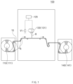
- FIG. 1 is a front view illustrating an example of an apparatus for manufacturing a secondary battery according to an embodiment of the present invention
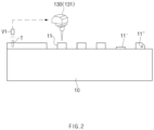
- FIG. 2 is a perspective view illustrating a first inspection process and a notching process in a method for manufacturing a secondary battery according to an embodiment of the present invention.
- a method for manufacturing a secondary battery comprises an electrode supply process of supplying an electrode 10, a first inspection process of detecting the electrode 10 to distinguish a normal electrode portion and an abnormal electrode portion from each other in a first inspection part V1, and a notching process of notching the electrode at a notching part 130.
- the normal electrode portion is notched to form an electrode tab 11, and the abnormal electrode portion is notched in at least one shape among a marked shape, a shape having a hole, among a shape of a cut electrode tab 11'.
- the notching part 130 irradiates the laser light B to a side end of the abnormal electrode portion in the electrode 10 through the laser 131 to notch the abnormal electrode portion so that the shape of the electrode tab 11 at the abnormal electrode portion is different from that of the electrode tab 11 at the normal electrode portion.
- the electrode 10 that is subjected to the first inspection process is notched in the notching part 130.
- the notching part 130 notches the normal electrode portion and the abnormal electrode portion, which are distinguished from each other in the first inspection part V1, in different shapes based on the received notching signal.
- the normal electrode portion is notched to form an electrode tab 11, and the abnormal electrode portion is notched in the form of at least one of a marked shape, a shape having a hole, or a shape of a cut electrode tab 11'.
- the notching part 130 irradiates the laser light B to a side end of the abnormal electrode portion in the electrode 10 through the laser 131 to notch the abnormal electrode portion so that the shape of the electrode tab 11 at the abnormal electrode portion is different from that of the electrode tab 11 at the normal electrode portion.
- the notched shape of the abnormal electrode portion may have a shape, in which an electrode tab 11' having a rectangular shape, in which a portion at which the electrode tab 11' is to be formed is short, is cut, a shape, in which an edge of a portion at which an electrode tab 11" is to be formed is chamfered, a marked shape in which a pattern is formed, or a shape in which a circular or polygonal hole is formed.
- the electrode 10 and the separator 20 may be alternately stacked to be laminated.
- heat and a pressure are applied to a stack S of the notched electrode 10 and the separator 20, and thus, the electrode and the separator 20 may be bonded to each other through the lamination part 260.
- the separator 20 wound around the separator supply roll 250 may be unwound to supply the separator 20 to the lamination part 260.
- the second inspection part V2 may detect an electrode portion notched as the abnormal electrode portion after the lamination process.
- a cut electrode tab 11', a mark, or a hole of the electrode portion notched as the abnormal electrode portion may be sensed through the second inspection part V2 comprising a vision sensor to detect the abnormal electrode portion, thereby transmitting a detection signal to a discharge part 280.
- the cut cells 30 may be transferred to a subsequent process through conveyor belts C1 and C2.
- the discharge part 280 may discharge defective cell 30' comprising the abnormal electrode portion detected through the second inspection process from the plurality of cells 30.
- the defective cell 30' comprising the abnormal electrode portion may be gripped through the discharge part 280 comprising a jig to separate the defective cell 30' from the cells comprising the normal electrode portion.
- the normal electrode portion and the abnormal electrode portion of the electrode 10 are notched in different shapes through the laser 131, and then, the defective cell 30' comprising the abnormal electrode portion, which is notched as the abnormal electrode portion, may be detected in the subsequent inspection process and then discharged in the discharge process. Therefore, a continuous operate may be possible without moving the equipment to significantly improve manufacturing productivity.
- an apparatus 100 for manufacturing a secondary battery comprises an electrode supply part 110 supplying an electrode 10, a first inspection part V1 detecting the supplied electrode 10 to distinguish a normal electrode portion and an abnormal electrode portion from each other, a notching part 130 notching the electrode 10 passing through the first inspection part V1, and a main control system 120 receiving a notching signal from the first inspection part V1 to transmit the notching signal to the notching part 130.
- the apparatus 100 for manufacturing the secondary battery according to an embodiment of the present invention may further comprise an electrode winding part 140 winding the electrode 10.
- the apparatus 100 for manufacturing the secondary battery according to an embodiment of the present invention relates to an apparatus for manufacturing the secondary battery applied to the method for manufacturing the secondary battery according to the forgoing embodiment and another embodiment of the present invention.
- an electrode supply part 110 may supply an electrode 10.
- the electrode supply part 110 comprises an electrode supply roll 111 on which the electrode 10 is wound, and the electrode 10 wound around the electrode supply roll 111 may be unwound to supply the electrode 10 to a position for the subsequent process.
- the electrode supply part 110 may adjust a supply rate of the electrode 10 according to a notching speed performed by a notching part 130.
- the electrode supply part 110 may comprise a rollers R supplying the electrode 10.
- a rotation speed of each of the rollers R may be adjusted to adjust the supply rate.
- the first inspection part V1 detects the supplied electrode 10 to distinguish a normal electrode portion and an abnormal electrode portion from each other.
- the first inspection part V1 transmits a notching signal by dividing the normal electrode portion and the abnormal electrode portion through a vision sensor.
- the first inspection part V1 senses a defective electrode display tag (NG Tag) T attached to a defective portion of the electrode 10 to detect the normal electrode portion and the abnormal electrode portion.
- NG Tag defective electrode display tag
- the notching part 130 notches the electrode 10 passing through the first inspection part V1.
- the notching part 130 notches the electrode 10 through a laser 131 so that the normal electrode portion and the abnormal electrode portion, which are detected in the first inspection part V1, are divided from each other.
- the notching part 130 notches the normal electrode portion and the abnormal electrode portion, which are distinguished from each other in the first inspection part V1, in different shapes based on the received notching signal.
- the notching part 130 may notch the normal electrode portion to form an electrode tab 11.
- the notching part 130 may irradiate a laser beam B to a side end of the normal electrode portion through the laser 131 to form the rectangular electrode tab 11.
- the notching part 130 may notch the abnormal electrode portion in the form of at least one of a marked shape, a shape having a hole, or a shape of a cut electrode tab 11'.
- the notching part 130 may irradiate the laser light B to a side end of the abnormal electrode portion in the electrode 10 through the laser 131 to notch the abnormal electrode portion so that the shape of the electrode tab 11 at the abnormal electrode portion is different from that of the electrode tab 11 at the normal electrode portion.
- the notched shape of the abnormal electrode portion may have a shape, in which an electrode tab 11' having a rectangular shape, in which a portion at which the electrode tab 11' is to be formed is short, is cut, a shape, in which an edge of a portion at which an electrode tab 11" is to be formed is chamfered, a marked shape in which a pattern is formed, or a shape in which a circular or polygonal hole is formed.
- the first inspection part V1 detects the supplied electrode 10 to distinguish a normal electrode portion and an abnormal electrode portion from each other.
- the first inspection part V1 transmits a notching signal by dividing the normal electrode portion and the abnormal electrode portion through a vision sensor.
- the lamination part 260 may alternately stack the notched electrode 10 and the separator 20 to laminate the electrode 10 and the separator 20.
- the lamination part 260 may press the stack S of the notched electrode 10 and the separator 20 while applying heat to bond the electrode 10 and the separator 20 to each other.
- the separator 20 wound around the separator supply roll 250 may be unwound to supply the separator 20 to the lamination part 260.
- the second inspection part V2 may detect an electrode portion notched as the abnormal electrode portion after passing through the lamination part 260.
- the second inspection part V2 may detect a cut electrode tab 11', a mark, or a hole of the electrode portion notched as the abnormal electrode portion through the vision sensor to detect the abnormal electrode portion, thereby transmitting a detection signal to a discharge part 280.
- the cell cutting part 270 may cut the stack S of the electrode 10 and the separator 20, which are laminated after passing through the second inspection part V2, into a plurality of cells 30.
- the cell cutting part 270 may comprise a pair of cutters and may cut the stack S of the electrode 10 and the separator 20, which is disposed between the pair of cutters, while moving the pair of cutters vertically.
- the cut cells 30 may be transferred to a subsequent process through conveyor belts C1 and C2.
- the discharge part 280 may discharge defective cells 30' comprising the abnormal electrode portion detected through the second inspection part V2 from the plurality of cells 30 after passing through the cell cutting part 270.
- the discharge part 280 may grip the defective cell 30' comprising the abnormal electrode portion through a jig to separate the defective cell 30' from the cells 30 comprising the normal electrode portion.
Landscapes
- Engineering & Computer Science (AREA)
- Chemical & Material Sciences (AREA)
- Chemical Kinetics & Catalysis (AREA)
- Electrochemistry (AREA)
- General Chemical & Material Sciences (AREA)
- Manufacturing & Machinery (AREA)
- Mechanical Engineering (AREA)
- Optics & Photonics (AREA)
- Physics & Mathematics (AREA)
- Plasma & Fusion (AREA)
- Life Sciences & Earth Sciences (AREA)
- Forests & Forestry (AREA)
- Secondary Cells (AREA)
Description
- The present application claims the benefit of the priority of
Korean Patent Application No. 10-2020-0065215, filed on May 29, 2020 - The present invention relates to a method for manufacturing a secondary battery and an apparatus for manufacturing a secondary battery.
- Secondary batteries are rechargeable unlike primarily batteries, and also, the possibility of compact size and high capacity is high. Thus, recently, many studies on secondary batteries are being carried out. As technology development and demands for mobile devices increase, the demands for secondary batteries as energy sources are rapidly increasing.
- Rechargeable batteries are classified into coin type batteries, cylindrical type batteries, prismatic type batteries, and pouch type batteries according to a shape of a battery case. In such a secondary battery, an electrode assembly mounted in a battery case is a chargeable and dischargeable power generating device having a structure in which an electrode and a separator are stacked.
- The electrode assembly may be approximately classified into a jelly roll type electrode assembly in which a separator is interposed between a positive electrode and a negative electrode, each of which is provided as the form of a sheet coated with an active material, and then, the positive electrode, the separator, and the negative electrode are wound, a stacked type electrode assembly in which a plurality of positive and negative electrodes with a separator therebetween are sequentially stacked, and a stack/folding type electrode assembly in which stacked type unit cells are wound together with a separation film having a long length.
- According to the related art, a notching process of the electrode is performed through a mold press. Here, in the case of the mold press, a shape is not changed in the notching unless the mold is exchanged, and when the electrode is determined as being defective before the notching process, an operation of the device may be stopped to display the defect by a person. Thereafter, even after the notching process, a production rate is reduced to be displayed and processed so as to display the defect. Thus, there is a problem in that manufacturing productivity is lowered.
- [Prior Art Document] (Patent Document)
Korean Patent Publication No. 10-2014-0015647 - Document
KR 2006/0034126 - Document
KR 2014/0009015 - Document
KR 101 958881 - One aspect of the present invention is to provide a method for manufacturing a secondary battery, which is capable of improving manufacturing productivity by enabling a continuous operation without moving equipment during manufacturing the secondary battery, and an apparatus for manufacturing a secondary battery.
- A method for manufacturing a secondary battery according to an embodiment of the present invention is disclosed in the attached claims.
- In addition, an apparatus for manufacturing a secondary battery is also provided.
- According to the present invention, the normal electrode portion and the abnormal electrode portion of the electrode is be notched into different shapes through the laser to perform the continuous operation without moving the equipment, thereby improving the manufacturing productivity. Thereafter, when the plurality of cells comprising the notched electrode are manufactured, the defective cell comprising the abnormal electrode portion that is notched as the abnormal electrode portion may be detected and discharged to perform the continuous operation without moving the equipment, thereby significantly improving the manufacturing productivity.
-
-
FIG. 1 is a front view illustrating an example of an apparatus for manufacturing a secondary battery according to an embodiment of the present invention. -
FIG. 2 is a perspective view illustrating a first inspection process and a notching process in a method for manufacturing a secondary battery according to an embodiment of the present invention. -
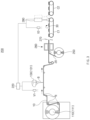
FIG. 3 is a front view illustrating an example of an apparatus for manufacturing a secondary battery according to another embodiment of the present invention. -
FIG. 4 is a perspective view illustrating a first inspection process and a notching process in a method for manufacturing a secondary battery according to another embodiment of the present invention. -
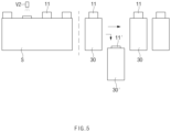
FIG. 5 is a perspective view illustrating a second inspection process, a cell cutting process, and a discharge process in the method for manufacturing the secondary battery according to another embodiment of the present invention. - The objectives, specific advantages, and novel features of the present invention will become more apparent from the following detailed description taken in conjunction with the accompanying drawings. It should be noted that the reference numerals are added to the components of the drawings in the present specification with the same numerals as possible, even if they are illustrated in other drawings. Also, the present invention may be embodied in different forms and should not be construed as limited to the embodiments set forth herein. In the following description of the present invention, the detailed descriptions of related arts which may unnecessarily obscure the gist of the present invention will be omitted.
-
FIG. 1 is a front view illustrating an example of an apparatus for manufacturing a secondary battery according to an embodiment of the present invention, andFIG. 2 is a perspective view illustrating a first inspection process and a notching process in a method for manufacturing a secondary battery according to an embodiment of the present invention. - Referring to
FIGS. 1 and2 , a method for manufacturing a secondary battery according to an embodiment of the present invention comprises an electrode supply process of supplying anelectrode 10, a first inspection process of detecting theelectrode 10 to distinguish a normal electrode portion and an abnormal electrode portion from each other in a first inspection part V1, and a notching process of notching the electrode at anotching part 130. - In addition, the method for manufacturing the secondary battery according to an embodiment of the present invention may further comprise a winding process of winding the
notched electrode 10 around anelectrode winding part 140. - In more detail, referring to
FIG. 1 , in the electrode supply process, theelectrode 10 may be supplied through theelectrode supply part 110. Here, theelectrode supply part 110 comprises anelectrode supply roll 111 on which theelectrode 10 is wound. In the electrode supply process, theelectrode 10 wound around theelectrode supply roll 111 may be unwound to supply theelectrode 10 to a position for the subsequent process. Here, theelectrode 10 may be wound around theelectrode supply roll 111 in various forms such as a sheet or film shape. - In the electrode supply process, a supply speed of the
electrode 10 may be adjusted according to a speed of the notching performed in the notching process. - In the electrode supply process, the
electrode supply part 110 may comprise a rollers R for supplying the electrode. Here, a rotation speed of each of the rollers R may be adjusted to adjust a supply rate. - In the first inspection process, the first inspection part V1 detects the supplied
electrode 10 to distinguish a normal electrode portion and an abnormal electrode portion from each other. - In addition, in the first inspection process, the first inspection part V1 divides the normal electrode portion from the abnormal electrode portion through a vision sensor and transmits a notching signal to the
notching part 130 through amain control system 120. Here, themain control system 120 may transmit a notch-type signal together when the notching signal is transmitted to thenotching part 130. In this case, the method for manufacturing the secondary battery according to an embodiment of the present invention may further comprise a control process of controlling thenotching part 130 in themain control system 120 to adjust a notched shape of theelectrode 10. - In addition, in the first inspection process, for example, the first inspection part V1 senses a defective electrode display tag (NG Tag) T attached to a defective portion of the
electrode 10 to detect the normal electrode portion and the abnormal electrode portion. In the first inspection process, for another example, the second inspection part V2 may sense a shape of theelectrode 10 to detect the normal electrode portion and the abnormal electrode portion. Here, the normal electrode portion and the abnormal electrode portion may be detected by sensing a width dimension, distortion, an applied state of an active material, etc., in theelectrode 10. - In the notching process, the
electrode 10 that is subjected to the first inspection process is notched in thenotching part 130. - In addition, in the notching process, the notching is performed by irradiating laser light B to the
electrode 10 through alaser 131 so that the normal electrode portion and the abnormal electrode portion, which are detected in the first inspection process, are divided from each other. - Furthermore, in the notching process, the
notching part 130 notches the normal electrode portion and the abnormal electrode portion, which are distinguished from each other in the first inspection part V1, in different shapes based on the received notching signal. - In the notching process, the normal electrode portion is notched to form an
electrode tab 11, and the abnormal electrode portion is notched in at least one shape among a marked shape, a shape having a hole, among a shape of a cut electrode tab 11'. Here, in the notching process, thenotching part 130 irradiates the laser light B to a side end of the abnormal electrode portion in theelectrode 10 through thelaser 131 to notch the abnormal electrode portion so that the shape of theelectrode tab 11 at the abnormal electrode portion is different from that of theelectrode tab 11 at the normal electrode portion. Here, in more detail, the notched shape of the abnormal electrode portion may have a shape, in which an electrode tab 11' having a rectangular shape, in which a portion at which the electrode tab 11' is to be formed is short, is cut, a shape, in which an edge of a portion at which anelectrode tab 11" is to be formed is chamfered, a marked shape in which a pattern is formed, or a shape in which a circular or polygonal hole is formed. - In the winding process, the
notched electrode 10 may be wound around theelectrode winding part 140. Here, theelectrode winding part 140 may comprise anelectrode winding roll 141, on which theelectrode 10 is wound, to wind theelectrode 10 moved in the winding process around theelectrode winding roll 141. - Referring to
FIGS. 1 and2 , in the method for manufacturing the secondary battery, which has the above-described configuration, according to an embodiment of the present invention, the normal electrode portion and the abnormal electrode portion in the suppliedelectrode 10 are distinguished from each other through the first inspection part V1 and then are notched in different shapes through thelaser 131 to perform a continuous process without moving equipment, thereby improving manufacturing productivity. - Hereinafter, a method for manufacturing a secondary battery according to another embodiment of the present invention will be described.
-
FIG. 3 is a front view illustrating an example of an apparatus for manufacturing a secondary battery according to another embodiment of the present invention,FIG. 4 is a perspective view illustrating a first inspection process and a notching process in a method for manufacturing a secondary battery according to another embodiment of the present invention, andFIG. 5 is a perspective view illustrating a second inspection process, a cell cutting process, and a discharge process in the method for manufacturing the secondary battery according to another embodiment of the present invention. - Referring to
FIGS. 3 and5 , a method for manufacturing a secondary battery according to another embodiment of the present invention comprises an electrode supply process of supplying anelectrode 10, a first inspection process of detecting theelectrode 10 to distinguish a normal electrode portion and an abnormal electrode portion from each other in a first inspection part V1, and a notching process of notching theelectrode 10 at a notchingpart 130. In addition, in the method for manufacturing the secondary battery according to another embodiment of the present invention may further comprise, after the notching process, a lamination process of laminating anelectrode 10 and aseparator 20, a second inspection process of an electrode portion notched as the abnormal electrode portion through a second inspection part V2, a cell cutting process of cutting the electrode portion into a plurality ofcells 30, and a discharge process of discharging a defective cell 30' comprising the abnormal electrode portion. - The method for manufacturing the secondary battery according to another embodiment of the present invention is different from the method for manufacturing the secondary battery according to the foregoing embodiment of the present invention in that the method for manufacturing the secondary battery according to another embodiment of the present invention further comprises the lamination process, the second inspection process, the cell cutting process, and the discharge process. Thus, in descriptions of the method for manufacturing the secondary battery according to another embodiment of the present invention, contents duplicated with the method for manufacturing the secondary battery according to the forgoing embodiment of the present invention will be omitted or briefly described, and also, differences therebetween will be mainly described.
- In more detail, referring to
FIGS. 3 to 5 , in the electrode supply process, theelectrode 10 may be supplied through theelectrode supply part 110. - In the electrode supply process, a supply speed of the
electrode 10 may be adjusted according to a speed of the notching performed in the notching process. - In the electrode supply process, the
electrode supply part 110 may comprise a rollers R supplying theelectrode 10. Here, a rotation speed of each of the rollers R may be adjusted to adjust a supply rate. - In the first inspection process, the first inspection part V1 detects the supplied
electrode 10 to distinguish a normal electrode portion and an abnormal electrode portion from each other. - In the first inspection process, the first inspection part V1 divides the normal electrode portion from the abnormal electrode portion through a vision sensor and transmits a notching signal to the notching
part 130 through amain control system 220. - In the notching process, the
electrode 10 that is subjected to the first inspection process is notched in the notchingpart 130. - In addition, in the notching process, the normal electrode portion and the abnormal electrode portion, which are detected in the first inspection process, are notched through a
laser 131 so as to be divided from each other. - Furthermore, in the notching process, the notching
part 130 notches the normal electrode portion and the abnormal electrode portion, which are distinguished from each other in the first inspection part V1, in different shapes based on the received notching signal. - In the notching process, the normal electrode portion is notched to form an
electrode tab 11, and the abnormal electrode portion is notched in the form of at least one of a marked shape, a shape having a hole, or a shape of a cut electrode tab 11'. Here, in the notching process, the notchingpart 130 irradiates the laser light B to a side end of the abnormal electrode portion in theelectrode 10 through thelaser 131 to notch the abnormal electrode portion so that the shape of theelectrode tab 11 at the abnormal electrode portion is different from that of theelectrode tab 11 at the normal electrode portion. Here, in more detail, the notched shape of the abnormal electrode portion may have a shape, in which an electrode tab 11' having a rectangular shape, in which a portion at which the electrode tab 11' is to be formed is short, is cut, a shape, in which an edge of a portion at which anelectrode tab 11" is to be formed is chamfered, a marked shape in which a pattern is formed, or a shape in which a circular or polygonal hole is formed. - In the lamination process, after the notching process, the
electrode 10 and theseparator 20 may be alternately stacked to be laminated. Here, in the lamination process, heat and a pressure are applied to a stack S of the notchedelectrode 10 and theseparator 20, and thus, the electrode and theseparator 20 may be bonded to each other through thelamination part 260. - Here, the
separator 20 wound around theseparator supply roll 250 may be unwound to supply theseparator 20 to thelamination part 260. - In the second inspection process, the second inspection part V2 may detect an electrode portion notched as the abnormal electrode portion after the lamination process. Here, in the second inspection process, a cut electrode tab 11', a mark, or a hole of the electrode portion notched as the abnormal electrode portion may be sensed through the second inspection part V2 comprising a vision sensor to detect the abnormal electrode portion, thereby transmitting a detection signal to a
discharge part 280. - In the cell cutting process, after the second inspection process, the stack S of the
electrode 10 and theseparator 20, which are laminated, may be cut into a plurality ofcells 30. Here, in the cell cutting process, the stack S of theelectrode 10 and theseparator 20, which is disposed between a pair of cutters, may be cut through acell cutting part 270 comprising the pair of cutters. - In this case, the
cut cells 30 may be transferred to a subsequent process through conveyor belts C1 and C2. - In the discharge process, after the cutting process, the
discharge part 280 may discharge defective cell 30' comprising the abnormal electrode portion detected through the second inspection process from the plurality ofcells 30. Here, in the discharge process, the defective cell 30' comprising the abnormal electrode portion may be gripped through thedischarge part 280 comprising a jig to separate the defective cell 30' from the cells comprising the normal electrode portion. - In the method for manufacturing the secondary battery according to another embodiment of the present invention configured as described above, the normal electrode portion and the abnormal electrode portion of the
electrode 10 are notched in different shapes through thelaser 131, and then, the defective cell 30' comprising the abnormal electrode portion, which is notched as the abnormal electrode portion, may be detected in the subsequent inspection process and then discharged in the discharge process. Therefore, a continuous operate may be possible without moving the equipment to significantly improve manufacturing productivity. - Hereinafter, an apparatus for manufacturing a secondary battery according to an embodiment of the present invention will be described.
- Referring to
FIGS. 1 and2 , anapparatus 100 for manufacturing a secondary battery according to an embodiment of the present invention comprises anelectrode supply part 110 supplying anelectrode 10, a first inspection part V1 detecting the suppliedelectrode 10 to distinguish a normal electrode portion and an abnormal electrode portion from each other, a notchingpart 130 notching theelectrode 10 passing through the first inspection part V1, and amain control system 120 receiving a notching signal from the first inspection part V1 to transmit the notching signal to the notchingpart 130. In addition, theapparatus 100 for manufacturing the secondary battery according to an embodiment of the present invention may further comprise anelectrode winding part 140 winding theelectrode 10. - The
apparatus 100 for manufacturing the secondary battery according to an embodiment of the present invention relates to an apparatus for manufacturing the secondary battery applied to the method for manufacturing the secondary battery according to the forgoing embodiment and another embodiment of the present invention. - Therefore, in descriptions of the
apparatus 100 for manufacturing the secondary battery according to this embodiment, contents duplicated with those of the apparatus according to the forgoing embodiment and another embodiment of the prevent invention will be omitted or briefly described, and differences will be mainly described. - In more detail, an
electrode supply part 110 may supply anelectrode 10. Here, theelectrode supply part 110 comprises anelectrode supply roll 111 on which theelectrode 10 is wound, and theelectrode 10 wound around theelectrode supply roll 111 may be unwound to supply theelectrode 10 to a position for the subsequent process. - Also, the
electrode supply part 110 may adjust a supply rate of theelectrode 10 according to a notching speed performed by a notchingpart 130. Here, theelectrode supply part 110 may comprise a rollers R supplying theelectrode 10. Here, a rotation speed of each of the rollers R may be adjusted to adjust the supply rate. - The first inspection part V1 detects the supplied
electrode 10 to distinguish a normal electrode portion and an abnormal electrode portion from each other. - In addition, the first inspection part V1 transmits a notching signal by dividing the normal electrode portion and the abnormal electrode portion through a vision sensor.
- For example, the first inspection part V1 senses a defective electrode display tag (NG Tag) T attached to a defective portion of the
electrode 10 to detect the normal electrode portion and the abnormal electrode portion. - For another example, a second inspection part V2 may sense a shape of the
electrode 10 to detect the normal electrode portion and the abnormal electrode portion. Here, the normal electrode portion and the abnormal electrode portion may be detected by sensing a width dimension, distortion, an applied state of an active material, etc., in theelectrode 10. - A
main control system 120 receives the notching signal from the first inspection part V1 to transmit the notching signal to the notchingpart 130. Here, themain control system 120 may transmit a notch-type signal together when the notching signal is transmitted to the notchingpart 130. That is, the notched shape of theelectrode 10 may be adjusted by controlling the notchingpart 130 in themain control system 120. - The notching
part 130 notches theelectrode 10 passing through the first inspection part V1. - In addition, the notching
part 130 notches theelectrode 10 through alaser 131 so that the normal electrode portion and the abnormal electrode portion, which are detected in the first inspection part V1, are divided from each other. - Furthermore, the notching
part 130 notches the normal electrode portion and the abnormal electrode portion, which are distinguished from each other in the first inspection part V1, in different shapes based on the received notching signal. - In addition, the notching
part 130 may notch the normal electrode portion to form anelectrode tab 11. Here, the notchingpart 130 may irradiate a laser beam B to a side end of the normal electrode portion through thelaser 131 to form therectangular electrode tab 11. - In addition, the notching
part 130 may notch the abnormal electrode portion in the form of at least one of a marked shape, a shape having a hole, or a shape of a cut electrode tab 11'. Here, the notchingpart 130 may irradiate the laser light B to a side end of the abnormal electrode portion in theelectrode 10 through thelaser 131 to notch the abnormal electrode portion so that the shape of theelectrode tab 11 at the abnormal electrode portion is different from that of theelectrode tab 11 at the normal electrode portion. Here, in more detail, the notched shape of the abnormal electrode portion may have a shape, in which an electrode tab 11' having a rectangular shape, in which a portion at which the electrode tab 11' is to be formed is short, is cut, a shape, in which an edge of a portion at which anelectrode tab 11" is to be formed is chamfered, a marked shape in which a pattern is formed, or a shape in which a circular or polygonal hole is formed. - An
electrode winding part 140 may wind the notchedelectrode 10 passing through the notchingpart 130. Here, theelectrode winding part 140 may comprise anelectrode winding roll 141, on which theelectrode 10 is wound, to wind the movingelectrode 10 around theelectrode winding roll 141. - Hereinafter, an apparatus for manufacturing a secondary battery according to another embodiment of the present invention will be described.
- Referring to
FIGS. 3 to 5 , anapparatus 200 for manufacturing a secondary battery according to another embodiment of the present invention comprises anelectrode supply part 110 supplying anelectrode 10, a first inspection part V1 detecting the suppliedelectrode 10 to distinguish a normal electrode portion and an abnormal electrode portion from each other, a notchingpart 130 notching theelectrode 10 passing through the first inspection part V1, amain control system 220 receiving a notching signal from the first inspection part V1 to transmit the notching signal to the notchingpart 130, alamination part 260 laminating the notchedelectrode 10 and aseparator 20, a second inspection part V2 detecting an electrode portion that is notched as the abnormal electrode portion, acell cutting part 270 cutting a stack S of theelectrode 10 and the separator into a plurality ofcells 30, and adischarge part 280 discharging a defective cell 30' comprising the abnormal electrode portion. - The
apparatus 200 for manufacturing the secondary battery according to another embodiment of the present invention is different from the apparatus for manufacturing the electrode assembly according to the foregoing embodiment of the present invention in that theapparatus 200 further comprises thelamination part 260, the second inspection part V2, thecell cutting part 270, and thedischarge part 280. - Therefore, in descriptions of the
apparatus 200 for manufacturing the secondary battery according to this embodiment, contents duplicated with those of the apparatus according to the forgoing embodiment of the prevent invention will be omitted or briefly described, and differences will be mainly described. - In more detail, in more detail, the
electrode supply part 110 may supply anelectrode 10. Here, theelectrode supply part 110 comprises anelectrode supply roll 111 on which theelectrode 10 is wound, and theelectrode 10 wound around theelectrode supply roll 111 may be unwound to supply theelectrode 10 to a position for the subsequent process. - Also, the
electrode supply part 110 may adjust a supply rate of theelectrode 10 according to a notching speed performed by a notchingpart 130. Here, theelectrode supply part 110 may comprise a rollers R supplying theelectrode 10. Here, a rotation speed of each of the rollers R may be adjusted to adjust the supply rate. - The first inspection part V1 detects the supplied
electrode 10 to distinguish a normal electrode portion and an abnormal electrode portion from each other. - The first inspection part V1 transmits a notching signal by dividing the normal electrode portion and the abnormal electrode portion through a vision sensor.
- The
main control system 220 receives the notching signal to transmit the notching signal to the notchingpart 130. Here, themain control system 220 may transmit a notch-type signal together when the notching signal is transmitted to the notchingpart 130. - The notching
part 130 notches theelectrode 10 passing through the first inspection part V1. - In addition, the notching
part 130 notches the electrode through alaser 131 so that the normal electrode portion and the abnormal electrode portion, which are detected in the first inspection part V1, are divided from each other. - The notching
part 130 notches the normal electrode portion and the abnormal electrode portion, which are distinguished from each other in the first inspection part V1, in different shapes based on the received notching signal. - The notching
part 130 may notch the normal electrode portion to form anelectrode tab 11 and notch the abnormal electrode portion in the form of at least one of a marked shape, a shape having a hole, or a shape of a cut electrode tab 11'. - The
lamination part 260 may alternately stack the notchedelectrode 10 and theseparator 20 to laminate theelectrode 10 and theseparator 20. Here, thelamination part 260 may press the stack S of the notchedelectrode 10 and theseparator 20 while applying heat to bond theelectrode 10 and theseparator 20 to each other. - Here, the
separator 20 wound around theseparator supply roll 250 may be unwound to supply theseparator 20 to thelamination part 260. - The second inspection part V2 may detect an electrode portion notched as the abnormal electrode portion after passing through the
lamination part 260. Here, the second inspection part V2 may detect a cut electrode tab 11', a mark, or a hole of the electrode portion notched as the abnormal electrode portion through the vision sensor to detect the abnormal electrode portion, thereby transmitting a detection signal to adischarge part 280. - The
cell cutting part 270 may cut the stack S of theelectrode 10 and theseparator 20, which are laminated after passing through the second inspection part V2, into a plurality ofcells 30. Here, thecell cutting part 270 may comprise a pair of cutters and may cut the stack S of theelectrode 10 and theseparator 20, which is disposed between the pair of cutters, while moving the pair of cutters vertically. - Then, the
cut cells 30 may be transferred to a subsequent process through conveyor belts C1 and C2. - The
discharge part 280 may discharge defective cells 30' comprising the abnormal electrode portion detected through the second inspection part V2 from the plurality ofcells 30 after passing through thecell cutting part 270. Here, thedischarge part 280 may grip the defective cell 30' comprising the abnormal electrode portion through a jig to separate the defective cell 30' from thecells 30 comprising the normal electrode portion. - While the present invention has been particularly shown and described with reference to exemplary embodiments thereof, it is to be understood that the scope of the present invention is not limited thereto. It will be understood by those of ordinary skill in the art that various changes in form and details may be made therein without departing from the scope of the present invention.
- Furthermore, the scope of protection of the present invention will be clarified by the appended claims.
-
- 10: Electrode
- 11, 11', 11": Electrode tab
- 20: Separator
- 30: Cell
- 100, 200: Apparatus for manufacturing secondary battery
- 110: Electrode supply part
- 111: Electrode supply roll
- 120: Main control system
- 130: Notching part
- 131: Laser
- 140: Electrode winding part
- 141: Electrode winding roll
- 250: Separator supply roll
- 260: Lamination part
- 270: Cell cutting part
- 280: Discharge part
- B: Laser light
- C1, C2: Conveyor belt
- R: Roller
- V1: First inspection part
- V2: Second inspection part
Claims (11)
- A method for manufacturing a secondary battery, the method comprising:an electrode supply process of supplying an electrode (10) through an electrode supply part (110);a first inspection process of detecting the supplied electrode (10) to distinguish a normal electrode portion and an abnormal electrode portion through a first inspection part (V1); anda notching process of notching the electrode (10), which is subjected to the first inspection process, in a notching part (130),wherein the notching process perform the notching through a laser so that the normal electrode portion and the abnormal electrode portion, which are detected in the first inspection process, are divided from each other;wherein, in the first inspection process, the first inspection part (V1) divides the normal electrode portion from the abnormal electrode portion through a vision sensor to transmit a notching signal to the notching part (130) through a main control system (120);wherein, in the notching process, the notching part (130) notches the normal electrode portion and the abnormal electrode portion, which are distinguished from each other in the first inspection part (V1), in different shapes based on the received notching signal.
- The method of claim 1, wherein, in the notching process, the normal electrode portion is notched to form an electrode tab (11), and
the abnormal electrode portion is notched in the form of at least one of a marked shape, a shape having a hole, or a shape of a cut electrode tab (11'). - The method of claim 1, wherein, in the electrode supply process, a supply rate of the electrode (10) is adjusted according to a speed of the notching performed in the notching process.
- The method of claim 3, wherein, in the electrode supply process, the electrode supply part (110) comprises rollers (R) that supply the electrode (10),
wherein each of the rollers (R) is adjusted in rotation speed to adjust the supply rate of the electrode (10). - The method of claim 1, further comprising a winding process of winding the electrode (10), which is subjected to the notching process, around an electrode winding part (140).
- The method of claim 1, further comprising, after the notching process:a lamination process of alternately stacking the electrode (10) and a separator (20) to laminate the electrode (10) and the separator (20);a second inspection process of detecting an electrode portion notched as the abnormal electrode portion through a second inspection part after the lamination process;a cell cutting process of cutting a stack (S) of the electrode (10) and the separator (20), which are laminated, into a plurality of cells (30) after the second inspection process; anda discharge process of discharging a defective cell (30') comprising the abnormal electrode portion, which is detected through the second inspection process, from the plurality of cells (30) through a discharge part (280) after the cutting process.
- An apparatus for manufacturing a secondary battery, the apparatus comprising:an electrode supply part (110) configured to supply an electrode (10);a first inspection part (V1) configured to detect the supplied electrode (10) so as to distinguish a normal electrode portion and an abnormal electrode portion from each other; anda notching part (130) configured to notch the electrode (10) passing through the first inspection part (V1),wherein the notching part (130) notches the electrode (10) through a laser so that the normal electrode portion and the abnormal electrode portion, which are detected in the first inspection part (V1), are divided from each other;wherein the first inspection part (V1) divides the normal electrode portion and the abnormal electrode portion from each other through a vision sensor to transmit a notching signal and the apparatus further comprises a main control system (120) configured to receive the notching signal so as to be transmitted to the notching part (130);wherein the notching part (130) notches the normal electrode portion and the abnormal electrode portion, which are distinguished from each other in the first inspection part (V1), in different shapes based on the received notching signal.
- The apparatus of claim 7, wherein the normal electrode portion is notched to form an electrode tab (11), and
the abnormal electrode portion is notched in the form of at least one of a marked shape, a shape having a hole, or a shape of a cut electrode tab (11'). - The apparatus of claim 7, wherein the electrode supply part (110) is configured to adjust a supply rate of the electrode (10) according to a speed of the notching performed in the notching part (130).
- The apparatus of claim 9, wherein the electrode supply part (110) comprises rollers (R) that supply the electrode (10),
wherein each of the rollers (R) is adjusted in rotation speed to adjust the supply rate of the electrode (10). - The apparatus of claim 7, further comprising:a lamination part (260) configured to alternately stack the electrode (10) and a separator (20) to be laminated;a second inspection part (V2) configured to detect an electrode portion notched as the abnormal electrode portion passing through the lamination part 260);a cell cutting part (270) configured to cut a stack (S) of the electrode (10) and the separator (20), which are laminated, into a plurality of cells (30)after passing through the second inspection part (V2); anda discharge part (280) configured to discharge a defective cell (30') comprising the abnormal electrode portion, which is detected through the second inspection part (V2), from the plurality of cells (30) after passing through the cutting part (270).
Applications Claiming Priority (2)
| Application Number | Priority Date | Filing Date | Title |
|---|---|---|---|
| KR1020200065215A KR102808443B1 (en) | 2020-05-29 | 2020-05-29 | Rechargeable battery manufacturing method and rechargeable battery manufactured manufacturing device |
| PCT/KR2021/006416 WO2021241960A1 (en) | 2020-05-29 | 2021-05-24 | Secondary battery manufacturing method and secondary battery manufacturing device |
Publications (3)
| Publication Number | Publication Date |
|---|---|
| EP4120384A1 EP4120384A1 (en) | 2023-01-18 |
| EP4120384A4 EP4120384A4 (en) | 2024-05-22 |
| EP4120384B1 true EP4120384B1 (en) | 2025-07-02 |
Family
ID=78744702
Family Applications (1)
| Application Number | Title | Priority Date | Filing Date |
|---|---|---|---|
| EP21813591.1A Active EP4120384B1 (en) | 2020-05-29 | 2021-05-24 | Method for manufacturing secondary battery and apparatus for manufacturing secondary battery |
Country Status (7)
| Country | Link |
|---|---|
| US (1) | US20230155101A1 (en) |
| EP (1) | EP4120384B1 (en) |
| KR (1) | KR102808443B1 (en) |
| CN (1) | CN115485874B (en) |
| ES (1) | ES3037408T3 (en) |
| HU (1) | HUE072737T2 (en) |
| WO (1) | WO2021241960A1 (en) |
Families Citing this family (11)
| Publication number | Priority date | Publication date | Assignee | Title |
|---|---|---|---|---|
| KR102853957B1 (en) * | 2021-12-20 | 2025-09-03 | 주식회사 엘지에너지솔루션 | System and method for inspecting exterior |
| KR20230112517A (en) | 2022-01-20 | 2023-07-27 | 전태호 | Apparatus for marking code and recognizing marked code, and integrated secondary battery cell management system |
| KR20230149983A (en) * | 2022-04-21 | 2023-10-30 | 주식회사 엘지에너지솔루션 | Lamination device, unit cell manufacturing method and unit cell |
| KR20240030290A (en) | 2022-08-30 | 2024-03-07 | 주식회사 엘지에너지솔루션 | Marking generation device |
| WO2024049133A1 (en) * | 2022-08-31 | 2024-03-07 | 주식회사 엘지에너지솔루션 | Cutting apparatus for electrode substrate |
| US20240097218A1 (en) * | 2022-09-15 | 2024-03-21 | Lg Energy Solution, Ltd. | Systems and methods for generating roll map and manufacturing battery using roll map |
| KR20240165650A (en) * | 2023-05-16 | 2024-11-25 | 주식회사 엘지에너지솔루션 | Electrode manufacturing device and electrode manufacturing method |
| DE102023206014A1 (en) * | 2023-06-27 | 2025-01-02 | Robert Bosch Gesellschaft mit beschränkter Haftung | Methods for monitoring and calibrating components in battery cell production |
| KR20250022362A (en) * | 2023-08-08 | 2025-02-17 | 주식회사 엘지에너지솔루션 | Secondary battery manufacturing apparatus and method for manufacturing a secondary battery using the same |
| HUP2500225A1 (en) * | 2024-07-19 | 2026-01-28 | Sk On Co., Ltd. | Complex production equipment and production system |
| CN121601722A (en) * | 2024-08-16 | 2026-03-03 | Sk新能源株式会社 | Composite device and device layout |
Family Cites Families (12)
| Publication number | Priority date | Publication date | Assignee | Title |
|---|---|---|---|---|
| JP2002042793A (en) * | 2000-07-18 | 2002-02-08 | Sony Corp | Winding device and winding method |
| KR100601562B1 (en) * | 2004-07-29 | 2006-07-19 | 삼성에스디아이 주식회사 | Electrode Assembly and Lithium Secondary Battery Using the Same |
| KR100601567B1 (en) * | 2004-10-18 | 2006-07-19 | 삼성에스디아이 주식회사 | Inspection device of electrode current collector and inspection method using the same |
| JP5383471B2 (en) * | 2009-12-22 | 2014-01-08 | 三菱重工業株式会社 | Electrode manufacturing system |
| KR101528001B1 (en) | 2012-06-22 | 2015-06-10 | 주식회사 엘지화학 | Electrode assembly, manufacture thereof, and secondary batteries including same |
| KR101479723B1 (en) * | 2012-07-06 | 2015-01-08 | 유일에너테크(주) | System for producing electrodes of battery and feeding apparatus used for the system |
| US10236497B2 (en) * | 2013-08-06 | 2019-03-19 | Nec Energy Devices, Ltd. | Intermittently coated battery electrode manufacturing method |
| JP6369645B2 (en) * | 2016-01-26 | 2018-08-08 | 株式会社豊田自動織機 | Electrode laminating apparatus and electrode laminating method |
| KR102003712B1 (en) * | 2016-10-26 | 2019-07-25 | 주식회사 엘지화학 | Electrode Tab-Feeding Device Comprising Guide for Positioning Electrode Tab at Correct Point |
| KR101926451B1 (en) * | 2017-08-03 | 2018-12-10 | 김기현 | Electrode processing apparatus for electrode of secondary battery |
| KR102558461B1 (en) * | 2018-06-20 | 2023-07-24 | 주식회사 엘지에너지솔루션 | Manufacturing method and apparatus for electrode stack |
| KR101958881B1 (en) * | 2018-12-06 | 2019-03-15 | (주)하나기술 | Electrode notching system for secondary battery |
-
2020
- 2020-05-29 KR KR1020200065215A patent/KR102808443B1/en active Active
-
2021
- 2021-05-24 EP EP21813591.1A patent/EP4120384B1/en active Active
- 2021-05-24 HU HUE21813591A patent/HUE072737T2/en unknown
- 2021-05-24 WO PCT/KR2021/006416 patent/WO2021241960A1/en not_active Ceased
- 2021-05-24 CN CN202180027345.4A patent/CN115485874B/en active Active
- 2021-05-24 US US17/917,405 patent/US20230155101A1/en active Pending
- 2021-05-24 ES ES21813591T patent/ES3037408T3/en active Active
Also Published As
| Publication number | Publication date |
|---|---|
| CN115485874B (en) | 2025-07-11 |
| WO2021241960A1 (en) | 2021-12-02 |
| US20230155101A1 (en) | 2023-05-18 |
| CN115485874A (en) | 2022-12-16 |
| ES3037408T3 (en) | 2025-10-01 |
| KR102808443B1 (en) | 2025-05-16 |
| EP4120384A1 (en) | 2023-01-18 |
| KR20210147658A (en) | 2021-12-07 |
| EP4120384A4 (en) | 2024-05-22 |
| HUE072737T2 (en) | 2025-12-28 |
Similar Documents
| Publication | Publication Date | Title |
|---|---|---|
| EP4120384A1 (en) | Secondary battery manufacturing method and secondary battery manufacturing device | |
| US12100796B2 (en) | Apparatus and method for manufacturing electrode assembly | |
| EP3930062B1 (en) | Method and apparatus for manufacturing electrode assembly of secondary battery | |
| EP4109613B1 (en) | Electrode manufacturing apparatus including electrode alignment unit and electrode assembly manufacturing apparatus including the same | |
| EP3955364A1 (en) | Electrode assembly manufacturing method, electrode assembly manufactured thereby and secondary battery | |
| CN104364955A (en) | Device which sandwiches electrode sheets with separators | |
| US20230126211A1 (en) | Separator Sheet Adhesion Apparatus | |
| KR102080346B1 (en) | High Speed Electrode Nothing System for Secondary Battery | |
| EP4027421B1 (en) | Electrode assembly production method comprising step for simultaneous application of heat and pressure | |
| KR102253132B1 (en) | Method For Manufacturing Unit Cell of Secondary Cell And The Apparatus And System Using the Same | |
| KR102465777B1 (en) | Manufacturing method and apparatus for electrode stack | |
| CN112652802A (en) | Lamination device | |
| US20230411669A1 (en) | Apparatus for Manufacturing Electrode Cell and Method for Controlling the Same | |
| US20230163431A1 (en) | Electrode Roll Connection Automation Apparatus | |
| JP6064558B2 (en) | Electrode body manufacturing method and electrode winding apparatus | |
| US20230148346A1 (en) | Apparatus and Method for Manufacturing Unit Cells | |
| US12374723B2 (en) | Method for manufacturing electrode assembly, electrode assembly manufactured therethrough, and secondary battery | |
| CN220290878U (en) | Device for manufacturing unit cell | |
| CN117546324A (en) | Electrode cutting device and battery cell manufacturing apparatus including the same | |
| KR102966904B1 (en) | Electrode supply device | |
| WO2020218088A1 (en) | Belt-shaped workpiece supply device | |
| KR20260013579A (en) | Battery and system and method of manufacturing the same | |
| KR20210157213A (en) | Manufacturing method of unit cell | |
| KR102858415B1 (en) | Apparatus for rolling electrode | |
| CN121511512A (en) | Adhesive tape for manufacturing battery modules, battery modules including battery cells attached to the adhesive tape for manufacturing battery modules, and methods for manufacturing battery modules. |
Legal Events
| Date | Code | Title | Description |
|---|---|---|---|
| STAA | Information on the status of an ep patent application or granted ep patent |
Free format text: STATUS: THE INTERNATIONAL PUBLICATION HAS BEEN MADE |
|
| PUAI | Public reference made under article 153(3) epc to a published international application that has entered the european phase |
Free format text: ORIGINAL CODE: 0009012 |
|
| STAA | Information on the status of an ep patent application or granted ep patent |
Free format text: STATUS: REQUEST FOR EXAMINATION WAS MADE |
|
| 17P | Request for examination filed |
Effective date: 20221014 |
|
| AK | Designated contracting states |
Kind code of ref document: A1 Designated state(s): AL AT BE BG CH CY CZ DE DK EE ES FI FR GB GR HR HU IE IS IT LI LT LU LV MC MK MT NL NO PL PT RO RS SE SI SK SM TR |
|
| DAV | Request for validation of the european patent (deleted) | ||
| DAX | Request for extension of the european patent (deleted) | ||
| A4 | Supplementary search report drawn up and despatched |
Effective date: 20240422 |
|
| RIC1 | Information provided on ipc code assigned before grant |
Ipc: B26D 1/00 20060101ALN20240416BHEP Ipc: H01M 10/42 20060101ALI20240416BHEP Ipc: H01M 10/04 20060101ALI20240416BHEP Ipc: B26D 5/34 20060101ALI20240416BHEP Ipc: B26D 1/06 20060101ALI20240416BHEP Ipc: B23K 101/36 20060101ALI20240416BHEP Ipc: B23K 26/08 20140101ALI20240416BHEP Ipc: B23K 26/03 20060101ALI20240416BHEP Ipc: B23K 26/38 20140101ALI20240416BHEP Ipc: B26F 1/12 20060101ALI20240416BHEP Ipc: H01M 50/531 20210101ALI20240416BHEP Ipc: H01M 4/04 20060101AFI20240416BHEP |
|
| GRAP | Despatch of communication of intention to grant a patent |
Free format text: ORIGINAL CODE: EPIDOSNIGR1 |
|
| STAA | Information on the status of an ep patent application or granted ep patent |
Free format text: STATUS: GRANT OF PATENT IS INTENDED |
|
| RIC1 | Information provided on ipc code assigned before grant |
Ipc: B26D 1/00 20060101ALN20250204BHEP Ipc: H01M 10/42 20060101ALI20250204BHEP Ipc: H01M 10/04 20060101ALI20250204BHEP Ipc: B26D 5/34 20060101ALI20250204BHEP Ipc: B26D 1/06 20060101ALI20250204BHEP Ipc: B23K 101/36 20060101ALI20250204BHEP Ipc: B23K 26/08 20140101ALI20250204BHEP Ipc: B23K 26/03 20060101ALI20250204BHEP Ipc: B23K 26/38 20140101ALI20250204BHEP Ipc: B26F 1/12 20060101ALI20250204BHEP Ipc: H01M 50/531 20210101ALI20250204BHEP Ipc: H01M 4/04 20060101AFI20250204BHEP |
|
| INTG | Intention to grant announced |
Effective date: 20250228 |
|
| GRAS | Grant fee paid |
Free format text: ORIGINAL CODE: EPIDOSNIGR3 |
|
| P01 | Opt-out of the competence of the unified patent court (upc) registered |
Free format text: CASE NUMBER: APP_13970/2025 Effective date: 20250321 |
|
| GRAA | (expected) grant |
Free format text: ORIGINAL CODE: 0009210 |
|
| STAA | Information on the status of an ep patent application or granted ep patent |
Free format text: STATUS: THE PATENT HAS BEEN GRANTED |
|
| AK | Designated contracting states |
Kind code of ref document: B1 Designated state(s): AL AT BE BG CH CY CZ DE DK EE ES FI FR GB GR HR HU IE IS IT LI LT LU LV MC MK MT NL NO PL PT RO RS SE SI SK SM TR |
|
| REG | Reference to a national code |
Ref country code: GB Ref legal event code: FG4D |
|
| REG | Reference to a national code |
Ref country code: CH Ref legal event code: EP |
|
| REG | Reference to a national code |
Ref country code: DE Ref legal event code: R096 Ref document number: 602021033496 Country of ref document: DE |
|
| REG | Reference to a national code |
Ref country code: IE Ref legal event code: FG4D |
|
| REG | Reference to a national code |
Ref country code: ES Ref legal event code: FG2A Ref document number: 3037408 Country of ref document: ES Kind code of ref document: T3 Effective date: 20251001 |
|
| REG | Reference to a national code |
Ref country code: NL Ref legal event code: MP Effective date: 20250702 |
|
| PG25 | Lapsed in a contracting state [announced via postgrant information from national office to epo] |
Ref country code: PT Free format text: LAPSE BECAUSE OF FAILURE TO SUBMIT A TRANSLATION OF THE DESCRIPTION OR TO PAY THE FEE WITHIN THE PRESCRIBED TIME-LIMIT Effective date: 20251103 |
|
| PG25 | Lapsed in a contracting state [announced via postgrant information from national office to epo] |
Ref country code: NL Free format text: LAPSE BECAUSE OF FAILURE TO SUBMIT A TRANSLATION OF THE DESCRIPTION OR TO PAY THE FEE WITHIN THE PRESCRIBED TIME-LIMIT Effective date: 20250702 |
|
| REG | Reference to a national code |
Ref country code: AT Ref legal event code: MK05 Ref document number: 1810297 Country of ref document: AT Kind code of ref document: T Effective date: 20250702 |
|
| REG | Reference to a national code |
Ref country code: HU Ref legal event code: AG4A Ref document number: E072737 Country of ref document: HU |
|
| PG25 | Lapsed in a contracting state [announced via postgrant information from national office to epo] |
Ref country code: IS Free format text: LAPSE BECAUSE OF FAILURE TO SUBMIT A TRANSLATION OF THE DESCRIPTION OR TO PAY THE FEE WITHIN THE PRESCRIBED TIME-LIMIT Effective date: 20251102 |
|
| PG25 | Lapsed in a contracting state [announced via postgrant information from national office to epo] |
Ref country code: NO Free format text: LAPSE BECAUSE OF FAILURE TO SUBMIT A TRANSLATION OF THE DESCRIPTION OR TO PAY THE FEE WITHIN THE PRESCRIBED TIME-LIMIT Effective date: 20251002 |
|
| REG | Reference to a national code |
Ref country code: LT Ref legal event code: MG9D |
|
| PG25 | Lapsed in a contracting state [announced via postgrant information from national office to epo] |
Ref country code: AT Free format text: LAPSE BECAUSE OF FAILURE TO SUBMIT A TRANSLATION OF THE DESCRIPTION OR TO PAY THE FEE WITHIN THE PRESCRIBED TIME-LIMIT Effective date: 20250702 |
|
| PG25 | Lapsed in a contracting state [announced via postgrant information from national office to epo] |
Ref country code: FI Free format text: LAPSE BECAUSE OF FAILURE TO SUBMIT A TRANSLATION OF THE DESCRIPTION OR TO PAY THE FEE WITHIN THE PRESCRIBED TIME-LIMIT Effective date: 20250702 |
|
| PG25 | Lapsed in a contracting state [announced via postgrant information from national office to epo] |
Ref country code: HR Free format text: LAPSE BECAUSE OF FAILURE TO SUBMIT A TRANSLATION OF THE DESCRIPTION OR TO PAY THE FEE WITHIN THE PRESCRIBED TIME-LIMIT Effective date: 20250702 |
|
| PG25 | Lapsed in a contracting state [announced via postgrant information from national office to epo] |
Ref country code: GR Free format text: LAPSE BECAUSE OF FAILURE TO SUBMIT A TRANSLATION OF THE DESCRIPTION OR TO PAY THE FEE WITHIN THE PRESCRIBED TIME-LIMIT Effective date: 20251003 |
|
| PG25 | Lapsed in a contracting state [announced via postgrant information from national office to epo] |
Ref country code: SE Free format text: LAPSE BECAUSE OF FAILURE TO SUBMIT A TRANSLATION OF THE DESCRIPTION OR TO PAY THE FEE WITHIN THE PRESCRIBED TIME-LIMIT Effective date: 20250702 Ref country code: CZ Free format text: LAPSE BECAUSE OF FAILURE TO SUBMIT A TRANSLATION OF THE DESCRIPTION OR TO PAY THE FEE WITHIN THE PRESCRIBED TIME-LIMIT Effective date: 20250702 |
|
| PG25 | Lapsed in a contracting state [announced via postgrant information from national office to epo] |
Ref country code: LV Free format text: LAPSE BECAUSE OF FAILURE TO SUBMIT A TRANSLATION OF THE DESCRIPTION OR TO PAY THE FEE WITHIN THE PRESCRIBED TIME-LIMIT Effective date: 20250702 |
|
| PG25 | Lapsed in a contracting state [announced via postgrant information from national office to epo] |
Ref country code: BG Free format text: LAPSE BECAUSE OF FAILURE TO SUBMIT A TRANSLATION OF THE DESCRIPTION OR TO PAY THE FEE WITHIN THE PRESCRIBED TIME-LIMIT Effective date: 20250702 Ref country code: PL Free format text: LAPSE BECAUSE OF FAILURE TO SUBMIT A TRANSLATION OF THE DESCRIPTION OR TO PAY THE FEE WITHIN THE PRESCRIBED TIME-LIMIT Effective date: 20250702 |
|
| PG25 | Lapsed in a contracting state [announced via postgrant information from national office to epo] |
Ref country code: RS Free format text: LAPSE BECAUSE OF FAILURE TO SUBMIT A TRANSLATION OF THE DESCRIPTION OR TO PAY THE FEE WITHIN THE PRESCRIBED TIME-LIMIT Effective date: 20251002 |
|
| PG25 | Lapsed in a contracting state [announced via postgrant information from national office to epo] |
Ref country code: SM Free format text: LAPSE BECAUSE OF FAILURE TO SUBMIT A TRANSLATION OF THE DESCRIPTION OR TO PAY THE FEE WITHIN THE PRESCRIBED TIME-LIMIT Effective date: 20250702 |
|
| PGFP | Annual fee paid to national office [announced via postgrant information from national office to epo] |
Ref country code: GB Payment date: 20260324 Year of fee payment: 6 |
|
| PG25 | Lapsed in a contracting state [announced via postgrant information from national office to epo] |
Ref country code: DK Free format text: LAPSE BECAUSE OF FAILURE TO SUBMIT A TRANSLATION OF THE DESCRIPTION OR TO PAY THE FEE WITHIN THE PRESCRIBED TIME-LIMIT Effective date: 20250702 |
|
| PG25 | Lapsed in a contracting state [announced via postgrant information from national office to epo] |
Ref country code: IT Free format text: LAPSE BECAUSE OF FAILURE TO SUBMIT A TRANSLATION OF THE DESCRIPTION OR TO PAY THE FEE WITHIN THE PRESCRIBED TIME-LIMIT Effective date: 20250702 |
|
| PG25 | Lapsed in a contracting state [announced via postgrant information from national office to epo] |
Ref country code: EE Free format text: LAPSE BECAUSE OF FAILURE TO SUBMIT A TRANSLATION OF THE DESCRIPTION OR TO PAY THE FEE WITHIN THE PRESCRIBED TIME-LIMIT Effective date: 20250702 Ref country code: SK Free format text: LAPSE BECAUSE OF FAILURE TO SUBMIT A TRANSLATION OF THE DESCRIPTION OR TO PAY THE FEE WITHIN THE PRESCRIBED TIME-LIMIT Effective date: 20250702 |
|
| PLBE | No opposition filed within time limit |
Free format text: ORIGINAL CODE: 0009261 |
|
| STAA | Information on the status of an ep patent application or granted ep patent |
Free format text: STATUS: NO OPPOSITION FILED WITHIN TIME LIMIT |