EP4119916A1 - Pressure sensor - Google Patents
Pressure sensor Download PDFInfo
- Publication number
- EP4119916A1 EP4119916A1 EP21764661.1A EP21764661A EP4119916A1 EP 4119916 A1 EP4119916 A1 EP 4119916A1 EP 21764661 A EP21764661 A EP 21764661A EP 4119916 A1 EP4119916 A1 EP 4119916A1
- Authority
- EP
- European Patent Office
- Prior art keywords
- detection unit
- strain detection
- pressure sensor
- electric power
- light
- Prior art date
- Legal status (The legal status is an assumption and is not a legal conclusion. Google has not performed a legal analysis and makes no representation as to the accuracy of the status listed.)
- Withdrawn
Links
- 238000001514 detection method Methods 0.000 claims abstract description 100
- 238000005192 partition Methods 0.000 claims description 14
- 239000000758 substrate Substances 0.000 description 28
- 239000012528 membrane Substances 0.000 description 22
- 230000000694 effects Effects 0.000 description 12
- 238000004891 communication Methods 0.000 description 7
- 238000010586 diagram Methods 0.000 description 7
- 238000009429 electrical wiring Methods 0.000 description 7
- 239000012530 fluid Substances 0.000 description 4
- 238000010248 power generation Methods 0.000 description 4
- 238000006073 displacement reaction Methods 0.000 description 3
- 238000003306 harvesting Methods 0.000 description 2
- 239000002184 metal Substances 0.000 description 2
- 230000003287 optical effect Effects 0.000 description 2
- 230000002093 peripheral effect Effects 0.000 description 2
- 239000000853 adhesive Substances 0.000 description 1
- 230000001070 adhesive effect Effects 0.000 description 1
- 239000003990 capacitor Substances 0.000 description 1
- 239000000919 ceramic Substances 0.000 description 1
- 230000008878 coupling Effects 0.000 description 1
- 238000010168 coupling process Methods 0.000 description 1
- 238000005859 coupling reaction Methods 0.000 description 1
- 238000000605 extraction Methods 0.000 description 1
- 238000009434 installation Methods 0.000 description 1
- 239000000463 material Substances 0.000 description 1
- 238000000034 method Methods 0.000 description 1
- 230000004048 modification Effects 0.000 description 1
- 238000012986 modification Methods 0.000 description 1
- 239000011347 resin Substances 0.000 description 1
- 229920005989 resin Polymers 0.000 description 1
- 229910001220 stainless steel Inorganic materials 0.000 description 1
- 239000010935 stainless steel Substances 0.000 description 1
- 239000010409 thin film Substances 0.000 description 1
- 238000003466 welding Methods 0.000 description 1
Images






Classifications
-
- G—PHYSICS
- G01—MEASURING; TESTING
- G01L—MEASURING FORCE, STRESS, TORQUE, WORK, MECHANICAL POWER, MECHANICAL EFFICIENCY, OR FLUID PRESSURE
- G01L19/00—Details of, or accessories for, apparatus for measuring steady or quasi-steady pressure of a fluent medium insofar as such details or accessories are not special to particular types of pressure gauges
- G01L19/0061—Electrical connection means
- G01L19/0084—Electrical connection means to the outside of the housing
-
- G—PHYSICS
- G01—MEASURING; TESTING
- G01L—MEASURING FORCE, STRESS, TORQUE, WORK, MECHANICAL POWER, MECHANICAL EFFICIENCY, OR FLUID PRESSURE
- G01L19/00—Details of, or accessories for, apparatus for measuring steady or quasi-steady pressure of a fluent medium insofar as such details or accessories are not special to particular types of pressure gauges
- G01L19/08—Means for indicating or recording, e.g. for remote indication
-
- G—PHYSICS
- G01—MEASURING; TESTING
- G01L—MEASURING FORCE, STRESS, TORQUE, WORK, MECHANICAL POWER, MECHANICAL EFFICIENCY, OR FLUID PRESSURE
- G01L19/00—Details of, or accessories for, apparatus for measuring steady or quasi-steady pressure of a fluent medium insofar as such details or accessories are not special to particular types of pressure gauges
- G01L19/14—Housings
- G01L19/148—Details about the circuit board integration, e.g. integrated with the diaphragm surface or encapsulation
Definitions
- the present invention relates to a pressure sensor using a strain gauge or the like
- a connector or a terminal is used for extracting an output signal of the sensor to the outside.
- a spring terminal is used for connecting an output terminal of the sensor to an outer pin.
- Patent Document 2 proposes a pressure sensor using a wireless communication module.
- the present invention has been achieved under such circumstances. It is an object of the invention to provide a pressure sensor for easy connection operation for extracting an output signal from a sensor unit.
- a pressure sensor comprises a sensor unit including:
- the output of the light radiated from the light emitting element into the space changes in response to the output signal of the strain detection unit. Since the change in the output of the light is detected by the light receiving element, the output signal detected by the strain detection unit can be easily extracted to the outside. Moreover, since the light receiving element is merely disposed corresponding to the light emitting element, the electrical wiring from the sensor unit is unnecessary. Moreover, since it is unnecessary to use a wireless communication module, no pairing operation or the like is also necessary, and the connection operation for extracting the output signal from the sensor unit is remarkably easy.
- the electric power supply means may include a piezoelectric element.
- the piezoelectric element is attached together with the strain detection unit to be able to supply an electric power generated by the deformation corresponding to pressure to the strain detection unit.
- an electromotive force due to deformation is generated in the piezoelectric element at the timing when the strain detection unit detects a deformation based on pressure, and an electric power is supplied from the piezoelectric element to the strain detection unit.
- low power consumption becomes possible.
- the electric power supply means may include a non-contact power receiving coil.
- the non-contact power receiving coil is constructed to receive an electric power and supply the electric power to the strain detection unit.
- the electric power supply means is not limited and is, for example, a battery, a charger, or the like.
- the electric power supply means may be a non-contact power receiving coil.
- the electric power supply means may include a circuit for adjusting a voltage or the like supplied to the strain detection unit.
- the electric power supply means may further include: a power storage element; and a switching means for selecting a power source for storing an electric power in the power storage element.
- the power storage element is constructed to supply the electric power stored therein to the strain detection unit.
- the strain detection unit may be operated by an energy harvesting element during normal operation, and the strain detection unit may be operated by switching to the battery or a wireless power supply during insufficient power generation.
- the pressure sensor according to the present invention may further comprise:
- the detection accuracy for pressure is improved by detecting the strain (deformation) using the plurality of strain detection units.
- the detection range can also be expanded by detecting the strain (deformation) using the plurality of strain detection units.
- the pressure sensor according to the present invention may further comprise a partition wall disposed between the light emitting element and the auxiliary light emitting element.
- a partition wall disposed between the light emitting element and the auxiliary light emitting element.
- the pressure sensor according to the present invention may further comprise a transmitting-side adapter provided with the sensor unit.
- the transmitting-side adapter is also provided with a membrane or the like that is displaced by receiving fluid pressure.
- the pressure sensor according to the present invention may further comprise: a receiving-side adapter capable of being (preferably, detachably or rotatably) attached to the transmitting-side adapter; and a light receiving element attached to the receiving-side adapter to be able to detect an output light radiated from the light emitting element.
- a receiving-side adapter capable of being (preferably, detachably or rotatably) attached to the transmitting-side adapter
- a light receiving element attached to the receiving-side adapter to be able to detect an output light radiated from the light emitting element.
- the light emitting element and the light receiving element face each other in a non-contact state with a predetermined gap only by (detachably) attaching the transmitting-side adapter to the receiving-side adapter, and the light from the light emitting element is radiated to the light receiving element.
- the positional displacement (including the rotational displacement) is acceptable.
- the transmitting-side adapter is connected (attached) to the receiving-side adapter only by a rough positioning, and this connection operation is extremely easy. Moreover, this connection operation does not require any operation such as electrical wiring and conduction connection. In addition, no operation such as pairing is necessary.
- the receiving-side adapter may comprise a signal processing means for processing a signal detected by the light receiving element.
- the receiving-side adapter may be attached with a cable connected to, for example, an external control device.
- a pressure sensor comprises a sensor unit including:
- the magnetic field radiated from the primary coil into the space changes corresponding to the output signal of the strain detection unit.
- the change in the magnetic field is detected with the secondary coil or the like electromagnetically induced and coupled in a non-contact manner, and the output signal detected by the strain detection unit can be thereby easily extracted to the outside. Since the secondary coil is merely disposed in a non-contact manner corresponding to the primary coil, electrical wiring from the sensor unit is unnecessary. Since it is not necessary to use a wireless communication module, a pairing operation or the like is unnecessary, and the connection operation for extracting the output signal from the sensor unit is remarkably easy.
- a pressure sensor 10 of the present embodiment includes a transmitting-side adapter 20 and a receiving-side adapter 50.
- the transmitting-side adapter 20 includes a holding member 24 provided with a membrane 22.
- the holding member 24 includes a hollow pressure introduction flow path 25. A fluid to be measured for its pressure is guided to an inner surface 22a of the membrane 22 via the flow path 25, and the membrane 22 is deformed and distorted by the pressure of the fluid.
- the membrane 22 is bonded to a holding base 26 of the holding member 24, but may be integrally formed with the holding base 26.
- the membrane 22 is integrally formed with, for example, a bottom plate of a stem, and the stem may be fixed to the holding member 24.
- the material of the membrane 22 is not limited, but is made of, for example, a metal such as stainless steel.
- a strain detection unit 32 as a part of a sensor unit 30 is closely fixed to an outer surface 22b of the membrane 22 at a location where a strain is generated by fluid pressure.
- the strain detection unit 32 is not limited as long as it is possible to detect a stress strain of the outer surface 22b based on the pressure applied to the inner surface 22a of the membrane 22.
- the strain detection unit 32 is a strain gauge resistor.
- the sensor unit 30 includes the strain detection unit 32, a battery 34, a power supply circuit 35, and a light emitting element 36.
- the battery 34 and the power supply circuit 35 correspond to a power supply means for supplying an electric power to the strain detection unit.
- the battery 34 is not limited and may be a primary battery, a secondary battery, or another battery.
- the power supply circuit 35 adjusts the voltage or electric current from the battery 34 (including the adjustment of the application timing) so as to adjust the electric power to the strain detection unit 32.
- the power supply circuit 35 may also have a role of storing electric power.
- the light emitting element 36 is connected to the strain detection unit 32 and is configured to emit a light by being applied an electric power (voltage and/or electric current) corresponding to the strain detected by the strain detection unit 32.
- the illuminance indicating the brightness of the light emitted by the light emitting element 36 corresponds to an output signal detected by the strain detection unit 32 based on the pressure applied to the inner surface 22a of the membrane 22 shown in FIG. 1 .
- the illuminance of light emission by the light emitting element 36 increases in proportion to the pressure applied to the inner surface 22a of the membrane 22 shown in FIG. 1 .
- the illuminance of the light emitted from the light emitting element 36 is measured by a light receiving element 66 shown in FIG. 3 , and the measured signal is subjected to signal processing by a signal processing circuit (signal processing means) 64 or the like, so that the pressure applied to the inner surface 22a of the membrane 22 can be calculated.
- the light receiving element 66 and the signal processing circuit 64 are communicably connected to each other, and the output signal from the signal processing circuit 64 can be transmitted to the outside via a cable 62.
- the output signal from the light receiving element 66 may be directly transmitted to the outside via the cable 62 without using the signal processing circuit 64.
- the light emitting element 36 is not limited and is, for example, an LED element, an LD element, or the like.
- the light receiving element 66 is not limited and is, for example, a phototransistor, a photodiode, an illuminance sensor, a CCD, a camera, or the like.
- the signal processing circuit 64 is not limited and is, for example, an MCU, an MPU, a CPU, an ASIC, or the like.
- the battery 34, the power supply circuit 35, and the light emitting element 36 are mounted on a light-emitting-side substrate 40, and the light-emitting-side substrate 40 is disposed so as not to contact with the membrane 22.
- an intermediate substrate 42 is disposed at an outer peripheral position of the membrane 22 with respect to the holding base 26 of the transmitting-side adapter 20, and the light-emitting-side substrate 40 is held by a plurality of wiring wires 44 with one ends fixed to the intermediate substrate 42.
- the strain detection unit 32 and the intermediate substrate 42 are electrically connected by wire bonding or the like, the wiring pattern of the intermediate substrate 42 and the wiring wires 44 are electrically connected, and the wiring wires 44 are connected to the wiring pattern of the light-emitting-side substrate 40.
- the wiring pattern of the light-emitting-side substrate 40 connects the battery 34, the power supply circuit 35, the strain detection unit 32, and the light emitting element 36.
- the wiring pattern of the intermediate substrate 42 and the wiring wires 44 shown in FIG. 2 are a part of the wiring connecting between the power supply circuit 35 and the strain detection unit 32 shown in FIG. 3 and are a part of the wiring connecting between the strain detection unit 32 and the light emitting element 36.
- the battery 34 and the power supply circuit 35 may be mounted on the intermediate substrate 42 without being mounted on the light-emitting-side substrate 40.
- the intermediate substrate 42 and the light-emitting-side substrate 40 may be integrated to eliminate either of them.
- the transmitting-side adapter 20 is formed with a convex engagement portion 28 protruding from the holding base 26 so as to surround the membrane 22 and the intermediate substrate 42.
- the receiving-side adapter 50 includes a light receiving element holding base 52 with a light-light-receiving-side substrate 60 fixed inside.
- the hollow cylindrical cover member 54 is formed on the outer periphery of the light receiving element holding base 52 so as to extend in the axial direction toward the transmitting-side adapter 20, and an inside 56 of the cover member 54 is open toward the transmitting-side adapter 20.
- the inside 56 of the cover member 54 is light-shielded from the outside, and no light other than the light from the light emitting element 36 enters the light receiving element 66.
- the transmitting-side adapter 20 and the receiving-side adapter 50 are made of a light-shielding member.
- the transmitting-side adapter 20 is made of a metal from the viewpoint of strength
- the receiving-side adapter 50 is made of a light-shielding resin, a light-shielding ceramic, or the like and preferably has an insulating property.
- the signal processing circuit 64 and the light receiving element 66 are fixed to the light-receiving-side substrate 60 and are connected by the wiring pattern of the substrate 60.
- the cable 62 is connected to the substrate 60 and is connected to, as shown in FIG. 3 , the signal processing circuit 64 and the light receiving element 66.
- the cable 62 is extracted from the inside of the receiving-side adapter 50 to the outside, and no light is inserted from this extracted part into the inside.
- the cable 62 is not limited as long as it is a signal line used as the wiring to the outside, and any cable used for electrical wiring or the like can be used.
- the cable 62 may be a cable for optical communication.
- the cable 62 may be directly connected to the light receiving element 66.
- the light receiving element 66 is disposed by being aligned to the light emitting element 36.
- the light emitting element 36 and the light receiving element 66 face each other in a combined state of the transmitting-side adapter 20 and the receiving-side adapter 50 and are arranged so as to face each other in a predetermined gap space.
- the predetermined gap space is not limited, but is preferably about 1.6 to 3.2 mm.
- the output of the light radiated from the light emitting element 36 into the space changes in response to the output signal of the strain detection unit 32. Since the change in the output of the light (e.g., the change in illuminance) is detected by the light receiving element 66, the output signal detected by the strain detection unit 32 can be easily extracted to the outside via the cable 62.
- the light receiving element 66 is merely disposed corresponding to the light emitting element 36, the electrical wiring from the sensor unit 30 to the cable 62 is unnecessary. Moreover, since it is unnecessary to use a wireless communication module, no pairing operation or the like is also necessary, and the operation for connecting the adapters 20 and 50 is remarkably easy due to extraction of the output signal from the sensor unit 30 to the cable 62.
- the concave engagement portion 58 of the receiving-side adapter 50 merely engages with the convex engagement portion 28 of the transmitting-side adapter 20. After the concave engagement portion 58 of the receiving-side adapter 50 engages with the convex engagement portion 28 of the transmitting-side adapter 20, they may be joined using an adhesive.
- the transmitting-side adapter 20 is provided with the convex engagement portion 28, and the receiving-side adapter 50 is provided with the concave engagement portion 58, but the reverse is also possible. That is, the transmitting-side adapter 20 may be provided with the concave engagement portion 58, and the receiving-side adapter 50 may be provided with the convex engagement portion 28.
- the cover member 54 is provided on the receiving-side adapter 50, but may be provided on the transmitting-side adapter 20. Instead, the cover member 54 may be provided on each of the adapters 20 and 50, and they may be connected by engagement or the like.
- the adapters 20 and 50 are connected by concave and convex engagement, but they may be connected by other connection means, such as screw coupling, bonding by adhesion, and bonding by welding.
- connection means such as screw coupling, bonding by adhesion, and bonding by welding.
- the light emitting element 36 and the light receiving element 66 face each other in a non-contact state with a predetermined gap only by (detachably) attaching the transmitting-side adapter 20 to the receiving-side adapter 50, and the light from the light emitting element 36 is radiated to the light receiving element 66.
- the transmitting-side adapter 20 is connected (attached) to the receiving-side adapter 50 only by a rough positioning, and this connection operation is extremely easy. Moreover, this connection operation does not require any operation such as electrical wiring and conduction connection. In addition, no operation such as pairing is necessary.
- a pressure sensor 10a according to the present embodiment is different from that in First Embodiment only in terms of the configurations and effects of a sensor unit 30a, and the other configurations and effects are similar to those in First Embodiment. The common respects are not described.
- the sensor unit 30a includes a piezoelectric element 34a instead of the battery 34 of First Embodiment.
- the piezoelectric element 34a is attached to the outer surface 22b of the membrane 22 together with the strain detection portion 32, but the attachment position is not limited as long as a deformation of the membrane 22 is also transmitted to the piezoelectric element 34a.
- the piezoelectric element 34a is deformed by a strain deformation based on the pressure applied to the membrane 22, and the electric power generated by this can be supplied to the strain detection unit 32.
- the circuit diagram of the pressure sensor 10a of the present embodiment is similar to the circuit diagram shown in FIG. 3 .
- an electromotive force due to the deformation of the element 34a is generated in the piezoelectric element 34a at the timing when the strain detection unit 32 detects a deformation based on the pressure applied to the membrane 22, and an electric power is supplied from the piezoelectric element 34a to the strain detection unit 32.
- low power consumption becomes possible.
- a pressure sensor 10b according to the present embodiment is different from that in First Embodiment or Second Embodiment only in terms of the configurations and effects of a sensor unit 30b and the configurations and effects of components mounted on the receiving-side adapter 50, and the other configurations and effects are similar to those in First Embodiment or Second Embodiment. The common respects are not described.
- the sensor unit 30b includes a non-contact power receiving coil 38 instead of the battery 34 of First Embodiment.
- the non-contact power receiving coil 38 is attached to the light-emitting-side substrate 40 and connected to the power supply circuit 35.
- a non-contact power feeding coil 68 is mounted on the light-receiving-side substrate 60 so as to face the non-contact power receiving coil 38 at a predetermined interval.
- the non-contact power feeding coil 68 is driven by a drive circuit 69 shown in FIG. 7 .
- the drive circuit 69 may be controlled by, for example, the signal processing circuit 64 or may be controlled by a control device or the like connected to the cable 62.
- the drive circuit 69 may be incorporated in the signal processing circuit 64 or may be incorporated in a control device or the like connected to the cable 62.
- An electric power can be supplied from an external power source (not shown) to the drive circuit 69.
- the electric power from the external power source may be supplied to the power feeding coil 68 via the cable 62.
- the power feeding coil 68 is electromagnetically coupled to the power receiving coil 38 in a non-contact manner, an electric power is supplied from the power feeding coil 68 to the power receiving coil 38, and the electric power supplied to the power receiving coil 38 is adjusted by the power supply circuit 35 and can be supplied to the strain detection unit 32 at a required timing.
- the power supply circuit 35 may further include a power storage element and a switching circuit (switching means) for selecting a power source for storing an electric power in the power storage element.
- the electric power stored in the power storage element of the power supply circuit 35 can be supplied to the strain detection unit 32.
- the power storage element is not limited and is, for example, a capacitor, a secondary battery, or the like.
- a pressure sensor 10c according to the present embodiment is different from that in First Embodiment to Third Embodiment only in terms of the configurations and effects of a sensor unit 30c and the configurations and effects of components mounted on the receiving-side adapter 50, and the other configurations and effects are similar to those in First Embodiment to Third Embodiment. The common respects are not described.
- the sensor unit 30c includes the piezoelectric element 34a and the non-contact power receiving coil 38 together with the battery 34 of First Embodiment.
- the non-contact power receiving coil 38 is attached to the light-emitting-side substrate 40 and connected to the power supply circuit 35.
- the non-contact power feeding coil 68 is mounted on the light-receiving-side substrate 60 so as to face the non-contact power receiving coil 38 at a predetermined interval.
- the non-contact power feeding coil 68 is driven by the drive circuit 69 shown in FIG. 9 .
- the drive circuit 69 may be controlled by, for example, the signal processing circuit 64 or may be controlled by a control device or the like connected to the cable 62.
- the drive circuit 69 may be incorporated in the signal processing circuit 64 or may be incorporated in a control device or the like connected to the cable 62.
- An electric power can be supplied from an external power source (not shown) to the drive circuit 69.
- the electric power from the external power source may be supplied to the power feeding coil 68 via the cable 62.
- the power feeding coil 68 is electromagnetically coupled to the power receiving coil 38 in a non-contact manner, an electric power is supplied from the power feeding coil 68 to the power receiving coil 38, and the electric power supplied to the power receiving coil 38 is adjusted by the power supply circuit 35 and can be supplied to the strain detection unit 32 at a required timing.
- the power supply circuit 35 may further include a power storage element and a switching circuit (switching means) for selecting a power source for storing an electric power in the power storage element. In that case, the electric power stored in the power storage element of the power supply circuit 35 can be supplied to the strain detection unit 32.
- various electric power generation elements e.g., the piezoelectric element 34a or a photovoltaic element
- the strain detection unit 32 may be operated by the piezoelectric element 34a as an energy harvesting element during normal operation, and the strain detection unit 32 may be operated by switching to the battery 34 or a wireless power supply (power supply between the coils 38 and 68) during insufficient power generation.
- a pressure sensor 10d according to the present embodiment is different from that in First Embodiment to Fourth Embodiment only in terms of the configurations and effects of a sensor unit 30d, and the other configurations and effects are similar to those in First Embodiment to Fourth Embodiment. The common respects are not described.
- the sensor unit 30d includes at least one auxiliary strain detection unit 32a disposed together with the strain detection unit 32 of First Embodiment.
- the sensor unit 30d includes at least one auxiliary light emitting element 36a together with the light emitting element 36.
- the auxiliary strain detection unit 32a has a configuration similar to that of the strain detection unit 32b, but does not necessarily have the same configuration.
- the auxiliary strain detection unit 32a is attached to the membrane 22 together with the strain detection unit 32, but the disposition position is not limited as long as a strain similar to that of the strain detection unit 32 is detected.
- the strain detection unit 32 and the auxiliary strain detection unit 32a may be formed on the outer surface 22b of the membrane 22 by a thin film method and laminated via an insulating layer.
- the strain detection unit 32 is connected to the power supply circuit 35 and the light emitting element 36, and the auxiliary strain detection unit 32a is connected to the power supply circuit 35 and the auxiliary light emitting element 36a.
- the auxiliary light emitting element 36a has a configuration similar to that of the light emitting element 36, but does not necessarily have the same configuration.
- a single light receiving element 66 faces both of the auxiliary light emitting element 36a and the light emitting element 36 and can receive the lights from both of them, but a plurality of light receiving elements 66 may be arranged on the receiving-side adapter 50 so as to face the respective light emitting elements 36 and 36a.
- the detection accuracy for pressure is improved by detecting the strain (deformation) using the plurality of strain detection units 32 and 32a.
- the detection range can also be expanded by detecting the strain (deformation) using the plurality of strain detection units 32 and 32a.
- a pressure sensor 10e according to the present embodiment is different from that in Fifth Embodiment only in terms of the configurations and effects of a sensor unit 30e, and the other configurations and effects are similar to those in Fifth Embodiment. The common respects are not described.
- the sensor unit 30e includes at least one auxiliary strain detection unit 32a disposed together with the strain detection unit 32.
- the sensor unit 30e includes at least one auxiliary light emitting element 36a together with the light emitting element 36.
- the strain detection unit 32 is connected to the power supply circuit 35 and the light emitting element 36, and the auxiliary strain detection unit 32a is connected to the power supply circuit 35 and the auxiliary light emitting element 36a.
- the auxiliary light emitting element 36a has a configuration similar to that of the light emitting element 36, but does not necessarily have the same configuration.
- the receiving-side adapter 50 is equipped with two hollow cylindrical partition walls 70 and 72 having different diameters.
- the partition wall 70 is disposed between the light emitting element 36 and the auxiliary light emitting element 36a in a combined state of the adapters 20 and 50 and prevents mutual interference of the lights emitted from the elements 36 and 36a.
- the partition wall 70 is also located between the light receiving element 66 and the auxiliary light receiving element 66a and is configured so that the lights entering the light receiving element 66 and the auxiliary light receiving element 66a, respectively, do not interfere with each other.
- the light emitting element 36 and the light receiving element 66 are arranged so as to face each other, and the auxiliary light emitting element 36a and the auxiliary light receiving element 66a are arranged so as to face each other.
- the hollow cylindrical partition wall 72 having a diameter larger than that of the partition wall 70 surrounds the light emitting element 36 so that the light from the light emitting element 36 does not leak to the outside.
- the two partition walls 70 and 72 are both mounted on the substrate 60 of the receiving-side adapter 50, but at least one of the partition walls 70 and 72 may be mounted on the substrate 40 of the transmitting-side adapter 20.
- the partition walls 70 and 72 are made of light-shielding members.
- the detection accuracy for pressure is improved by detecting the strain (deformation) using the plurality of strain detection units 32 and 32a.
- the detection range can be expanded by detecting the strain (deformation) using the plurality of strain detection units 32 and 32a.
- the partition wall 70 Since at least the partition wall 70 is provided, it is possible to prevent the interference of the output lights from the plurality of light emitting elements 36 and 36a, and the output lights from the plurality of light emitting elements 36 and 36a can be detected separately by the light receiving elements 66 and 66a. Thus, it is possible to compare those detection signals and improve the detection accuracy. In addition, it is possible to detect the failure of either of them, and the redundancy is improved.
- the partition walls 70 and 72 are formed with a hollow cylindrical shape, even if one adapter 50 rotates relative to the other adapter 20, the output lights from the plurality of light emitting elements 36 and 36a can be detected separately by the light receiving elements 66 and 66a while preventing the interference of the output lights.
- the signal lines, such as the cable 62 are not twisted and can be used for applications, such as a robot arm and a surveillance camera.
- the pressure sensor of the present embodiment is a modification of the pressure sensor 10b shown in FIG. 6 and FIG. 7 .
- the common respects are not described.
- the pressure sensor of the present embodiment includes a primary coil for changing the magnetic field radiated into the space in response to the output signal of the strain detection unit 32.
- the pressure sensor of the present embodiment includes a secondary coil facing the primary coil in a non-contact manner. The secondary coil is connected to the signal processing circuit 64 or the like.
- the magnetic field radiated from the primary coil into the space changes corresponding to the output signal of the strain detection unit 32.
- the change in the magnetic field is detected with the secondary coil or the like electromagnetically induced and coupled in a non-contact manner, and the output signal detected by the strain detection unit can be thereby easily extracted to the outside. Since the secondary coil is merely disposed in a non-contact manner corresponding to the primary coil, electrical wiring from the sensor unit is unnecessary. Since it is unnecessary to use a wireless communication module, a pairing operation or the like is unnecessary, and the connection operation for extracting the output signal from the sensor unit is remarkably easy.
- the non-contact power receiving coil 38 can also function as the primary coil.
- the non-contact feeding coil 68 can also function as the secondary coil. In that case, the primary coil and the secondary coil corresponding to the light emitting element 36 and the light receiving element 66 can also be omitted.
Landscapes
- Physics & Mathematics (AREA)
- General Physics & Mathematics (AREA)
- Measuring Fluid Pressure (AREA)
Abstract
Description
- The present invention relates to a pressure sensor using a strain gauge or the like
- In a conventional pressure sensor, a connector or a terminal is used for extracting an output signal of the sensor to the outside. In the pressure sensor shown in Patent Document 1 below, for example, instead of a connector, a spring terminal is used for connecting an output terminal of the sensor to an outer pin.
- When a connector is used for connection to the sensor, tension is applied to the wiring at the time of connection, and the wiring may be torn. In the case of a spring, a contact is poor even if the position is merely slightly displaced, and an output signal may not be able to be extracted to the outside. In addition, a physical force is applied to a connector or a spring pin, and they can thus be damaged during setting.
- In any case, it is necessary to set an outer housing including an external connector to a sensor and perform an engagement in consideration of an inner terminal at the same time, and this operation is complicated. Patent Document 2 below proposes a pressure sensor using a wireless communication module.
- In the pressure sensor using the wireless communication module, however, a pairing operation between a transmitting-side wireless device and a receiving-side wireless device is necessary, and this also takes time and effort for installation operation.
-
- Patent Document 1:
JP2018151192 (A - Patent Document 2:
JP2017181493 (A - The present invention has been achieved under such circumstances. It is an object of the invention to provide a pressure sensor for easy connection operation for extracting an output signal from a sensor unit.
- To achieve the above-mentioned object, a pressure sensor according to the present invention comprises a sensor unit including:
- a strain detection unit for detecting a deformation corresponding to pressure;
- an electric power supply means for supplying an electric power to the strain detection unit; and
- a light emitting element capable of changing an output of a light radiated into space in response to an output signal of the strain detection unit.
- In the pressure sensor according to the present invention, the output of the light radiated from the light emitting element into the space changes in response to the output signal of the strain detection unit. Since the change in the output of the light is detected by the light receiving element, the output signal detected by the strain detection unit can be easily extracted to the outside. Moreover, since the light receiving element is merely disposed corresponding to the light emitting element, the electrical wiring from the sensor unit is unnecessary. Moreover, since it is unnecessary to use a wireless communication module, no pairing operation or the like is also necessary, and the connection operation for extracting the output signal from the sensor unit is remarkably easy.
- The electric power supply means may include a piezoelectric element. In this case, preferably, the piezoelectric element is attached together with the strain detection unit to be able to supply an electric power generated by the deformation corresponding to pressure to the strain detection unit. In this configuration, an electromotive force due to deformation is generated in the piezoelectric element at the timing when the strain detection unit detects a deformation based on pressure, and an electric power is supplied from the piezoelectric element to the strain detection unit. As a result, low power consumption becomes possible.
- The electric power supply means may include a non-contact power receiving coil. In this case, preferably, the non-contact power receiving coil is constructed to receive an electric power and supply the electric power to the strain detection unit. The electric power supply means is not limited and is, for example, a battery, a charger, or the like. The electric power supply means may be a non-contact power receiving coil. Moreover, the electric power supply means may include a circuit for adjusting a voltage or the like supplied to the strain detection unit.
- The electric power supply means may further include: a power storage element; and a switching means for selecting a power source for storing an electric power in the power storage element. In this case, preferably, the power storage element is constructed to supply the electric power stored therein to the strain detection unit.
- When the switching means is used, for example, various electric power generation elements can be used as a backup power source for the battery. For example, the strain detection unit may be operated by an energy harvesting element during normal operation, and the strain detection unit may be operated by switching to the battery or a wireless power supply during insufficient power generation.
- The pressure sensor according to the present invention may further comprise:
- an auxiliary strain detection unit disposed together with the strain detection unit; and
- an auxiliary light emitting element capable of changing an output of a light radiated into space in response to an output signal of the auxiliary strain detection unit.
- The detection accuracy for pressure is improved by detecting the strain (deformation) using the plurality of strain detection units. Instead, the detection range can also be expanded by detecting the strain (deformation) using the plurality of strain detection units.
- The pressure sensor according to the present invention may further comprise a partition wall disposed between the light emitting element and the auxiliary light emitting element. When the partition wall is provided, it is possible to prevent the interference of the output lights from the plurality of light emitting elements, and the output lights from the plurality of light emitting elements can be detected separately by the light receiving elements. Thus, it is possible to compare those detection signals and improve the detection accuracy. In addition, it is possible to detect the failure of either of them, and the redundancy is improved.
- The pressure sensor according to the present invention may further comprise a transmitting-side adapter provided with the sensor unit. Preferably, the transmitting-side adapter is also provided with a membrane or the like that is displaced by receiving fluid pressure.
- The pressure sensor according to the present invention may further comprise: a receiving-side adapter capable of being (preferably, detachably or rotatably) attached to the transmitting-side adapter; and a light receiving element attached to the receiving-side adapter to be able to detect an output light radiated from the light emitting element.
- Preferably, the light emitting element and the light receiving element face each other in a non-contact state with a predetermined gap only by (detachably) attaching the transmitting-side adapter to the receiving-side adapter, and the light from the light emitting element is radiated to the light receiving element. As long as the light from the light emitting element is radiated to the light receiving element, the positional displacement (including the rotational displacement) is acceptable. The transmitting-side adapter is connected (attached) to the receiving-side adapter only by a rough positioning, and this connection operation is extremely easy. Moreover, this connection operation does not require any operation such as electrical wiring and conduction connection. In addition, no operation such as pairing is necessary.
- The receiving-side adapter may comprise a signal processing means for processing a signal detected by the light receiving element. The receiving-side adapter may be attached with a cable connected to, for example, an external control device.
- A pressure sensor according to another aspect of the present invention comprises a sensor unit including:
- a strain detection unit for detecting a deformation corresponding to pressure;
- an electric power supply means for supplying an electric power to the strain detection unit; and
- a primary coil capable of changing a magnetic field radiated into space in response to an output signal of the strain detection unit.
- In the pressure sensor according to another aspect of the present embodiment, the magnetic field radiated from the primary coil into the space changes corresponding to the output signal of the strain detection unit. The change in the magnetic field is detected with the secondary coil or the like electromagnetically induced and coupled in a non-contact manner, and the output signal detected by the strain detection unit can be thereby easily extracted to the outside. Since the secondary coil is merely disposed in a non-contact manner corresponding to the primary coil, electrical wiring from the sensor unit is unnecessary. Since it is not necessary to use a wireless communication module, a pairing operation or the like is unnecessary, and the connection operation for extracting the output signal from the sensor unit is remarkably easy.
-
-
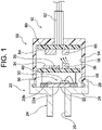
FIG. 1 is a schematic cross-sectional view of a pressure sensor according to an embodiment of the present invention; -
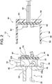
FIG. 2 is an exploded view of the pressure sensor shown inFIG. 1 before assembly; -
FIG. 3 is a circuit diagram of the pressure sensor shown inFIG. 1 ; -
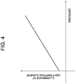
FIG. 4 is a graph illustrating a relation between a pressure detected by a strain detection unit shown inFIG. 3 and an illuminance from a light emitting element; -
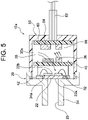
FIG. 5 is a schematic cross-sectional view of a pressure sensor according to another embodiment of the present invention; -
FIG. 6 is a schematic cross-sectional view of a pressure sensor according to still another embodiment of the present invention; -
FIG. 7 is a circuit diagram of the pressure sensor shown inFIG. 6 ; -
FIG. 8 is a schematic cross-sectional view of a pressure sensor according to still another embodiment of the present invention; -
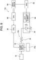
FIG. 9 is a circuit diagram of the pressure sensor shown inFIG. 8 ; -
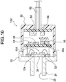
FIG. 10 is a schematic cross-sectional view of a pressure sensor according to still another embodiment of the present invention; -
FIG. 11 is a circuit diagram of the pressure sensor shown inFIG. 10 ; -
FIG. 12 is a schematic cross-sectional view of a pressure sensor according to still another embodiment of the present invention; -
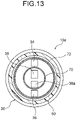
FIG. 13 is a cross-sectional view taken along the line XIII-XIII of the pressure sensor shown inFIG. 12 ; -
FIG. 14 is an exploded view of the pressure sensor shown inFIG. 12 before assembly; and -
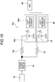
FIG. 15 is a circuit diagram of the pressure sensor shown inFIG. 12 . - Hereinafter, the present invention is described based on embodiments shown in the figures.
- As shown in
FIG. 1 , apressure sensor 10 of the present embodiment includes a transmitting-side adapter 20 and a receiving-side adapter 50. The transmitting-side adapter 20 includes a holdingmember 24 provided with amembrane 22. The holdingmember 24 includes a hollow pressureintroduction flow path 25. A fluid to be measured for its pressure is guided to aninner surface 22a of themembrane 22 via theflow path 25, and themembrane 22 is deformed and distorted by the pressure of the fluid. - In the present embodiment, the
membrane 22 is bonded to a holdingbase 26 of the holdingmember 24, but may be integrally formed with the holdingbase 26. Themembrane 22 is integrally formed with, for example, a bottom plate of a stem, and the stem may be fixed to the holdingmember 24. The material of themembrane 22 is not limited, but is made of, for example, a metal such as stainless steel. - A
strain detection unit 32 as a part of asensor unit 30 is closely fixed to anouter surface 22b of themembrane 22 at a location where a strain is generated by fluid pressure. Thestrain detection unit 32 is not limited as long as it is possible to detect a stress strain of theouter surface 22b based on the pressure applied to theinner surface 22a of themembrane 22. In the present embodiment, for example, thestrain detection unit 32 is a strain gauge resistor. - In the present embodiment, the
sensor unit 30 includes thestrain detection unit 32, abattery 34, apower supply circuit 35, and alight emitting element 36. In the present embodiment, thebattery 34 and thepower supply circuit 35 correspond to a power supply means for supplying an electric power to the strain detection unit. Thebattery 34 is not limited and may be a primary battery, a secondary battery, or another battery. - As shown in
FIG. 3 , thepower supply circuit 35 adjusts the voltage or electric current from the battery 34 (including the adjustment of the application timing) so as to adjust the electric power to thestrain detection unit 32. Thepower supply circuit 35 may also have a role of storing electric power. - The
light emitting element 36 is connected to thestrain detection unit 32 and is configured to emit a light by being applied an electric power (voltage and/or electric current) corresponding to the strain detected by thestrain detection unit 32. The illuminance indicating the brightness of the light emitted by thelight emitting element 36 corresponds to an output signal detected by thestrain detection unit 32 based on the pressure applied to theinner surface 22a of themembrane 22 shown inFIG. 1 . - For example, as shown in
FIG. 4 , the illuminance of light emission by thelight emitting element 36 increases in proportion to the pressure applied to theinner surface 22a of themembrane 22 shown inFIG. 1 . Thus, the illuminance of the light emitted from thelight emitting element 36 is measured by alight receiving element 66 shown inFIG. 3 , and the measured signal is subjected to signal processing by a signal processing circuit (signal processing means) 64 or the like, so that the pressure applied to theinner surface 22a of themembrane 22 can be calculated. - The
light receiving element 66 and thesignal processing circuit 64 are communicably connected to each other, and the output signal from thesignal processing circuit 64 can be transmitted to the outside via acable 62. The output signal from thelight receiving element 66 may be directly transmitted to the outside via thecable 62 without using thesignal processing circuit 64. - In the present embodiment, the
light emitting element 36 is not limited and is, for example, an LED element, an LD element, or the like. As long as the brightness (illuminance) of the light from thelight emitting element 36 can be detected, thelight receiving element 66 is not limited and is, for example, a phototransistor, a photodiode, an illuminance sensor, a CCD, a camera, or the like. Thesignal processing circuit 64 is not limited and is, for example, an MCU, an MPU, a CPU, an ASIC, or the like. - In the present embodiment, as shown in
FIG. 2 , thebattery 34, thepower supply circuit 35, and thelight emitting element 36 are mounted on a light-emitting-side substrate 40, and the light-emitting-side substrate 40 is disposed so as not to contact with themembrane 22. In the present embodiment, anintermediate substrate 42 is disposed at an outer peripheral position of themembrane 22 with respect to the holdingbase 26 of the transmitting-side adapter 20, and the light-emitting-side substrate 40 is held by a plurality ofwiring wires 44 with one ends fixed to theintermediate substrate 42. - The
strain detection unit 32 and theintermediate substrate 42 are electrically connected by wire bonding or the like, the wiring pattern of theintermediate substrate 42 and thewiring wires 44 are electrically connected, and thewiring wires 44 are connected to the wiring pattern of the light-emitting-side substrate 40. As shown inFIG. 3 , the wiring pattern of the light-emitting-side substrate 40 connects thebattery 34, thepower supply circuit 35, thestrain detection unit 32, and thelight emitting element 36. The wiring pattern of theintermediate substrate 42 and thewiring wires 44 shown inFIG. 2 are a part of the wiring connecting between thepower supply circuit 35 and thestrain detection unit 32 shown inFIG. 3 and are a part of the wiring connecting between thestrain detection unit 32 and thelight emitting element 36. - The
battery 34 and thepower supply circuit 35 may be mounted on theintermediate substrate 42 without being mounted on the light-emitting-side substrate 40. Theintermediate substrate 42 and the light-emitting-side substrate 40 may be integrated to eliminate either of them. - The transmitting-
side adapter 20 is formed with aconvex engagement portion 28 protruding from the holdingbase 26 so as to surround themembrane 22 and theintermediate substrate 42. Aconcave engagement portion 58 formed on the outer peripheral surface of the tip of acover member 54 of the receiving-side adapter 50 engages with theconvex engagement portion 28. - The receiving-
side adapter 50 includes a light receivingelement holding base 52 with a light-light-receiving-side substrate 60 fixed inside. The hollowcylindrical cover member 54 is formed on the outer periphery of the light receivingelement holding base 52 so as to extend in the axial direction toward the transmitting-side adapter 20, and an inside 56 of thecover member 54 is open toward the transmitting-side adapter 20. As shown inFIG. 1 , since theconcave engagement portion 58 of thecover member 54 engages with theconvex engagement portion 28 of the transmitting-side adapter 20, the inside 56 of thecover member 54 is light-shielded from the outside, and no light other than the light from thelight emitting element 36 enters thelight receiving element 66. - That is, preferably, the transmitting-
side adapter 20 and the receiving-side adapter 50 are made of a light-shielding member. For example, the transmitting-side adapter 20 is made of a metal from the viewpoint of strength, and the receiving-side adapter 50 is made of a light-shielding resin, a light-shielding ceramic, or the like and preferably has an insulating property. - The
signal processing circuit 64 and thelight receiving element 66 are fixed to the light-receiving-side substrate 60 and are connected by the wiring pattern of thesubstrate 60. Thecable 62 is connected to thesubstrate 60 and is connected to, as shown inFIG. 3 , thesignal processing circuit 64 and thelight receiving element 66. Thecable 62 is extracted from the inside of the receiving-side adapter 50 to the outside, and no light is inserted from this extracted part into the inside. - The
cable 62 is not limited as long as it is a signal line used as the wiring to the outside, and any cable used for electrical wiring or the like can be used. Thecable 62 may be a cable for optical communication. Thecable 62 may be directly connected to thelight receiving element 66. Thelight receiving element 66 is disposed by being aligned to thelight emitting element 36. In the present embodiment, as shown inFIG. 1 , thelight emitting element 36 and thelight receiving element 66 face each other in a combined state of the transmitting-side adapter 20 and the receiving-side adapter 50 and are arranged so as to face each other in a predetermined gap space. The predetermined gap space is not limited, but is preferably about 1.6 to 3.2 mm. - In the
pressure sensor 10 according to the present embodiment, the output of the light radiated from thelight emitting element 36 into the space changes in response to the output signal of thestrain detection unit 32. Since the change in the output of the light (e.g., the change in illuminance) is detected by thelight receiving element 66, the output signal detected by thestrain detection unit 32 can be easily extracted to the outside via thecable 62. - In the present embodiment, since the
light receiving element 66 is merely disposed corresponding to thelight emitting element 36, the electrical wiring from thesensor unit 30 to thecable 62 is unnecessary. Moreover, since it is unnecessary to use a wireless communication module, no pairing operation or the like is also necessary, and the operation for connecting theadapters sensor unit 30 to thecable 62. - In the present embodiment, the
concave engagement portion 58 of the receiving-side adapter 50 merely engages with theconvex engagement portion 28 of the transmitting-side adapter 20. After theconcave engagement portion 58 of the receiving-side adapter 50 engages with theconvex engagement portion 28 of the transmitting-side adapter 20, they may be joined using an adhesive. In the present embodiment, the transmitting-side adapter 20 is provided with theconvex engagement portion 28, and the receiving-side adapter 50 is provided with theconcave engagement portion 58, but the reverse is also possible. That is, the transmitting-side adapter 20 may be provided with theconcave engagement portion 58, and the receiving-side adapter 50 may be provided with theconvex engagement portion 28. - In the present embodiment, the
cover member 54 is provided on the receiving-side adapter 50, but may be provided on the transmitting-side adapter 20. Instead, thecover member 54 may be provided on each of theadapters - In the present embodiment, the
adapters side adapter 50 is detachably attached to the transmitting-side adapter 20 in an engagement manner, it is easy to maintain the internal parts of the adapters. - In the present embodiment, the
light emitting element 36 and thelight receiving element 66 face each other in a non-contact state with a predetermined gap only by (detachably) attaching the transmitting-side adapter 20 to the receiving-side adapter 50, and the light from thelight emitting element 36 is radiated to thelight receiving element 66. As long as the light from thelight emitting element 36 is radiated to thelight receiving element 66, a slight positional displacement is acceptable. The transmitting-side adapter 20 is connected (attached) to the receiving-side adapter 50 only by a rough positioning, and this connection operation is extremely easy. Moreover, this connection operation does not require any operation such as electrical wiring and conduction connection. In addition, no operation such as pairing is necessary. - As shown in
FIG. 5 , apressure sensor 10a according to the present embodiment is different from that in First Embodiment only in terms of the configurations and effects of asensor unit 30a, and the other configurations and effects are similar to those in First Embodiment. The common respects are not described. - In the present embodiment, as shown in
FIG. 5 , thesensor unit 30a includes apiezoelectric element 34a instead of thebattery 34 of First Embodiment. Thepiezoelectric element 34a is attached to theouter surface 22b of themembrane 22 together with thestrain detection portion 32, but the attachment position is not limited as long as a deformation of themembrane 22 is also transmitted to thepiezoelectric element 34a. Thepiezoelectric element 34a is deformed by a strain deformation based on the pressure applied to themembrane 22, and the electric power generated by this can be supplied to thestrain detection unit 32. The circuit diagram of thepressure sensor 10a of the present embodiment is similar to the circuit diagram shown inFIG. 3 . - In the
pressure sensor 10a of the present embodiment, an electromotive force due to the deformation of theelement 34a is generated in thepiezoelectric element 34a at the timing when thestrain detection unit 32 detects a deformation based on the pressure applied to themembrane 22, and an electric power is supplied from thepiezoelectric element 34a to thestrain detection unit 32. As a result, low power consumption becomes possible. - As shown in
FIG. 6 andFIG. 7 , apressure sensor 10b according to the present embodiment is different from that in First Embodiment or Second Embodiment only in terms of the configurations and effects of asensor unit 30b and the configurations and effects of components mounted on the receiving-side adapter 50, and the other configurations and effects are similar to those in First Embodiment or Second Embodiment. The common respects are not described. - In the present embodiment, as shown in
FIG. 6 andFIG. 7 , thesensor unit 30b includes a non-contactpower receiving coil 38 instead of thebattery 34 of First Embodiment. The non-contactpower receiving coil 38 is attached to the light-emitting-side substrate 40 and connected to thepower supply circuit 35. - A non-contact
power feeding coil 68 is mounted on the light-receiving-side substrate 60 so as to face the non-contactpower receiving coil 38 at a predetermined interval. The non-contactpower feeding coil 68 is driven by adrive circuit 69 shown inFIG. 7 . Thedrive circuit 69 may be controlled by, for example, thesignal processing circuit 64 or may be controlled by a control device or the like connected to thecable 62. Thedrive circuit 69 may be incorporated in thesignal processing circuit 64 or may be incorporated in a control device or the like connected to thecable 62. - An electric power can be supplied from an external power source (not shown) to the
drive circuit 69. The electric power from the external power source may be supplied to thepower feeding coil 68 via thecable 62. Thepower feeding coil 68 is electromagnetically coupled to thepower receiving coil 38 in a non-contact manner, an electric power is supplied from thepower feeding coil 68 to thepower receiving coil 38, and the electric power supplied to thepower receiving coil 38 is adjusted by thepower supply circuit 35 and can be supplied to thestrain detection unit 32 at a required timing. - In the present embodiment, the
power supply circuit 35 may further include a power storage element and a switching circuit (switching means) for selecting a power source for storing an electric power in the power storage element. In that case, the electric power stored in the power storage element of thepower supply circuit 35 can be supplied to thestrain detection unit 32. The power storage element is not limited and is, for example, a capacitor, a secondary battery, or the like. - As shown in
FIG. 8 andFIG. 9 , apressure sensor 10c according to the present embodiment is different from that in First Embodiment to Third Embodiment only in terms of the configurations and effects of asensor unit 30c and the configurations and effects of components mounted on the receiving-side adapter 50, and the other configurations and effects are similar to those in First Embodiment to Third Embodiment. The common respects are not described. - In the present embodiment, as shown in
FIG. 8 andFIG. 9 , thesensor unit 30c includes thepiezoelectric element 34a and the non-contactpower receiving coil 38 together with thebattery 34 of First Embodiment. The non-contactpower receiving coil 38 is attached to the light-emitting-side substrate 40 and connected to thepower supply circuit 35. - The non-contact
power feeding coil 68 is mounted on the light-receiving-side substrate 60 so as to face the non-contactpower receiving coil 38 at a predetermined interval. The non-contactpower feeding coil 68 is driven by thedrive circuit 69 shown inFIG. 9 . Thedrive circuit 69 may be controlled by, for example, thesignal processing circuit 64 or may be controlled by a control device or the like connected to thecable 62. Thedrive circuit 69 may be incorporated in thesignal processing circuit 64 or may be incorporated in a control device or the like connected to thecable 62. - An electric power can be supplied from an external power source (not shown) to the
drive circuit 69. The electric power from the external power source may be supplied to thepower feeding coil 68 via thecable 62. Thepower feeding coil 68 is electromagnetically coupled to thepower receiving coil 38 in a non-contact manner, an electric power is supplied from thepower feeding coil 68 to thepower receiving coil 38, and the electric power supplied to thepower receiving coil 38 is adjusted by thepower supply circuit 35 and can be supplied to thestrain detection unit 32 at a required timing. - In the present embodiment, the
power supply circuit 35 may further include a power storage element and a switching circuit (switching means) for selecting a power source for storing an electric power in the power storage element. In that case, the electric power stored in the power storage element of thepower supply circuit 35 can be supplied to thestrain detection unit 32. - When the switching circuit of the
power supply circuit 35 is used, for example, various electric power generation elements (e.g., thepiezoelectric element 34a or a photovoltaic element) can be used as a backup power source for thebattery 34. For example, thestrain detection unit 32 may be operated by thepiezoelectric element 34a as an energy harvesting element during normal operation, and thestrain detection unit 32 may be operated by switching to thebattery 34 or a wireless power supply (power supply between thecoils 38 and 68) during insufficient power generation. - As shown in
FIG. 10 andFIG. 11 , apressure sensor 10d according to the present embodiment is different from that in First Embodiment to Fourth Embodiment only in terms of the configurations and effects of asensor unit 30d, and the other configurations and effects are similar to those in First Embodiment to Fourth Embodiment. The common respects are not described. - In the present embodiment, as shown in
FIG. 10 andFIG. 11 , thesensor unit 30d includes at least one auxiliarystrain detection unit 32a disposed together with thestrain detection unit 32 of First Embodiment. Thesensor unit 30d includes at least one auxiliarylight emitting element 36a together with thelight emitting element 36. The auxiliarystrain detection unit 32a has a configuration similar to that of the strain detection unit 32b, but does not necessarily have the same configuration. The auxiliarystrain detection unit 32a is attached to themembrane 22 together with thestrain detection unit 32, but the disposition position is not limited as long as a strain similar to that of thestrain detection unit 32 is detected. Thestrain detection unit 32 and the auxiliarystrain detection unit 32a may be formed on theouter surface 22b of themembrane 22 by a thin film method and laminated via an insulating layer. - The
strain detection unit 32 is connected to thepower supply circuit 35 and thelight emitting element 36, and the auxiliarystrain detection unit 32a is connected to thepower supply circuit 35 and the auxiliarylight emitting element 36a. The auxiliarylight emitting element 36a has a configuration similar to that of thelight emitting element 36, but does not necessarily have the same configuration. In the present embodiment, a singlelight receiving element 66 faces both of the auxiliarylight emitting element 36a and thelight emitting element 36 and can receive the lights from both of them, but a plurality of light receivingelements 66 may be arranged on the receiving-side adapter 50 so as to face the respectivelight emitting elements - In the present embodiment, the detection accuracy for pressure is improved by detecting the strain (deformation) using the plurality of
strain detection units strain detection units - As shown in
FIG. 12 to FIG. 15 , apressure sensor 10e according to the present embodiment is different from that in Fifth Embodiment only in terms of the configurations and effects of asensor unit 30e, and the other configurations and effects are similar to those in Fifth Embodiment. The common respects are not described. - In the present embodiment, as shown in
FIG. 12 to FIG. 15 , thesensor unit 30e includes at least one auxiliarystrain detection unit 32a disposed together with thestrain detection unit 32. Thesensor unit 30e includes at least one auxiliarylight emitting element 36a together with thelight emitting element 36. - The
strain detection unit 32 is connected to thepower supply circuit 35 and thelight emitting element 36, and the auxiliarystrain detection unit 32a is connected to thepower supply circuit 35 and the auxiliarylight emitting element 36a. The auxiliarylight emitting element 36a has a configuration similar to that of thelight emitting element 36, but does not necessarily have the same configuration. In the present embodiment, the receiving-side adapter 50 is equipped with two hollowcylindrical partition walls - As shown in
FIG. 12 , thepartition wall 70 is disposed between the light emittingelement 36 and the auxiliarylight emitting element 36a in a combined state of theadapters elements partition wall 70 is also located between the light receivingelement 66 and the auxiliarylight receiving element 66a and is configured so that the lights entering thelight receiving element 66 and the auxiliarylight receiving element 66a, respectively, do not interfere with each other. - In the present embodiment, the
light emitting element 36 and thelight receiving element 66 are arranged so as to face each other, and the auxiliarylight emitting element 36a and the auxiliarylight receiving element 66a are arranged so as to face each other. The hollowcylindrical partition wall 72 having a diameter larger than that of thepartition wall 70 surrounds thelight emitting element 36 so that the light from thelight emitting element 36 does not leak to the outside. - In the present embodiment, the two
partition walls substrate 60 of the receiving-side adapter 50, but at least one of thepartition walls substrate 40 of the transmitting-side adapter 20. Thepartition walls - In the present embodiment, the detection accuracy for pressure is improved by detecting the strain (deformation) using the plurality of
strain detection units strain detection units - Since at least the
partition wall 70 is provided, it is possible to prevent the interference of the output lights from the plurality oflight emitting elements light emitting elements light receiving elements - In the present embodiment, since the
partition walls adapter 50 rotates relative to theother adapter 20, the output lights from the plurality oflight emitting elements light receiving elements adapter 50 is relatively rotatably engaged with theother adapter 20, the signal lines, such as thecable 62, are not twisted and can be used for applications, such as a robot arm and a surveillance camera. - Although not illustrated, the pressure sensor of the present embodiment is a modification of the
pressure sensor 10b shown inFIG. 6 andFIG. 7 . The common respects are not described. - Instead of the
optical sensor 36, the pressure sensor of the present embodiment includes a primary coil for changing the magnetic field radiated into the space in response to the output signal of thestrain detection unit 32. Moreover, instead of thelight receiving element 66, the pressure sensor of the present embodiment includes a secondary coil facing the primary coil in a non-contact manner. The secondary coil is connected to thesignal processing circuit 64 or the like. - In the pressure sensor of the present embodiment, the magnetic field radiated from the primary coil into the space changes corresponding to the output signal of the
strain detection unit 32. The change in the magnetic field is detected with the secondary coil or the like electromagnetically induced and coupled in a non-contact manner, and the output signal detected by the strain detection unit can be thereby easily extracted to the outside. Since the secondary coil is merely disposed in a non-contact manner corresponding to the primary coil, electrical wiring from the sensor unit is unnecessary. Since it is unnecessary to use a wireless communication module, a pairing operation or the like is unnecessary, and the connection operation for extracting the output signal from the sensor unit is remarkably easy. - In the present embodiment, the non-contact
power receiving coil 38 can also function as the primary coil. Moreover, thenon-contact feeding coil 68 can also function as the secondary coil. In that case, the primary coil and the secondary coil corresponding to thelight emitting element 36 and thelight receiving element 66 can also be omitted. - The present invention is not limited to the above-mentioned embodiments and can be variously modified within the scope of the present invention.
-
- 10, 10a-10e...
- pressure sensor
- 20...
- transmitting-side adapter
- 22...
- membrane
22a... inner surface
22b... outer surface - 24...
- holding member
- 25...
- pressure introduction flow path
- 26...
- holding base
- 28...
- convex engagement portion
- 30, 30a-30e...
- sensor unit
- 32...
- strain detection unit
32a... auxiliary strain detection unit - 34...
- battery
34a... piezoelectric element - 35...
- power supply circuit
- 36...
- light emitting element
36a... auxiliary light emitting element - 38...
- non-contact power receiving coil
- 40...
- light-emitting-side substrate
- 42...
- intermediate substrate
- 44...
- wiring wire
- 50...
- receiving-side adapter
- 52...
- light receiving element holding base
- 54...
- cover member
- 56...
- inside
- 58...
- concave engagement portion
- 60...
- light-receiving-side substrate
- 62...
- cable
- 64...
- signal processing circuit (signal processing means)
- 66...
- light receiving element
66a... auxiliary light receiving element - 68...
- non-contact power feeding coil
- 69...
- drive circuit
- 70, 72 ...
- partition wall
Claims (10)
- A pressure sensor comprising a sensor unit including:a strain detection unit for detecting a deformation corresponding to pressure;an electric power supply means for supplying an electric power to the strain detection unit; anda light emitting element capable of changing an output of a light radiated into space in response to an output signal of the strain detection unit.
- The pressure sensor according to claim 1, whereinthe electric power supply means includes a piezoelectric element, andthe piezoelectric element is attached together with the strain detection unit to be able to supply an electric power generated by the deformation corresponding to pressure to the strain detection unit.
- The pressure sensor according to claim 1 or 2, whereinthe electric power supply means includes a non-contact power receiving coil, andthe non-contact power receiving coil is constructed to receive an electric power and supply the electric power to the strain detection unit.
- The pressure sensor according to any of claims 1 to 3, whereinthe electric power supply means further includes:a power storage element; anda switching means for selecting a power source for storing an electric power in the power storage element, andthe power storage element is constructed to supply the electric power stored therein to the strain detection unit.
- The pressure sensor according to any of claims 1 to 4, further comprising:an auxiliary strain detection unit disposed together with the strain detection unit; andan auxiliary light emitting element capable of changing an output of a light radiated into space in response to an output signal of the auxiliary strain detection unit.
- The pressure sensor according to claim 5, further comprising a partition wall disposed between the light emitting element and the auxiliary light emitting element.
- The pressure sensor according to any of claims 1 to 6, further comprising a transmitting-side adapter provided with the sensor unit.
- The pressure sensor according to claim 7, further comprising:a receiving-side adapter capable of being attached to the transmitting-side adapter; anda light receiving element attached to the receiving-side adapter to be able to detect an output light radiated from the light emitting element.
- The pressure sensor according to claim 8, wherein the receiving-side adapter comprises a signal processing means for processing a signal detected by the light receiving element.
- A pressure sensor comprising a sensor unit including:a strain detection unit for detecting a deformation corresponding to pressure;an electric power supply means for supplying an electric power to the strain detection unit; anda primary coil capable of changing a magnetic field radiated into space in response to an output signal of the strain detection unit.
Applications Claiming Priority (2)
| Application Number | Priority Date | Filing Date | Title |
|---|---|---|---|
| JP2020037982A JP2021139759A (en) | 2020-03-05 | 2020-03-05 | Pressure sensor |
| PCT/JP2021/005558 WO2021177014A1 (en) | 2020-03-05 | 2021-02-15 | Pressure sensor |
Publications (2)
| Publication Number | Publication Date |
|---|---|
| EP4119916A1 true EP4119916A1 (en) | 2023-01-18 |
| EP4119916A4 EP4119916A4 (en) | 2024-06-05 |
Family
ID=77612702
Family Applications (1)
| Application Number | Title | Priority Date | Filing Date |
|---|---|---|---|
| EP21764661.1A Withdrawn EP4119916A4 (en) | 2020-03-05 | 2021-02-15 | Pressure sensor |
Country Status (3)
| Country | Link |
|---|---|
| EP (1) | EP4119916A4 (en) |
| JP (1) | JP2021139759A (en) |
| WO (1) | WO2021177014A1 (en) |
Families Citing this family (1)
| Publication number | Priority date | Publication date | Assignee | Title |
|---|---|---|---|---|
| JP7588677B2 (en) * | 2023-04-25 | 2024-11-22 | ソフトバンク株式会社 | Power supply system and switching circuit |
Family Cites Families (16)
| Publication number | Priority date | Publication date | Assignee | Title |
|---|---|---|---|---|
| US6672151B1 (en) * | 1989-12-20 | 2004-01-06 | Sentech, Inc. | Apparatus and method for remote sensing and receiving |
| JP3137121B2 (en) * | 1990-04-09 | 2001-02-19 | 株式会社ブリヂストン | Tire internal monitoring device |
| JPH06307957A (en) * | 1993-04-20 | 1994-11-04 | Omron Corp | Capacitance type mechanical quantity sensor and mechanical quantity detection device |
| JP3333905B2 (en) * | 1994-03-25 | 2002-10-15 | 新コスモス電機株式会社 | Explosion-proof gas detector and its calibration method |
| JP3561223B2 (en) * | 2000-09-20 | 2004-09-02 | パンチ工業株式会社 | Gas pressure measuring device for gas spring |
| JP2003006779A (en) * | 2001-06-22 | 2003-01-10 | Nsk Ltd | Wheel rotation support device having signal transmission function |
| US7140257B2 (en) * | 2002-12-10 | 2006-11-28 | Ashcroft Inc. | Wireless transmitting pressure measurement device |
| DE202004000428U1 (en) * | 2003-02-20 | 2004-10-21 | Wagner, Gerhard | Pressure monitor e.g. for control room, monitors pressures to 2000 Pa by diagonal tubing manometer and light barrier with electronic circuit operated battery and when adjusted pressure is exceeded optical and acoustic signal is produced |
| US20070107523A1 (en) * | 2005-10-31 | 2007-05-17 | Galewski Carl J | Distributed Pressure Sensoring System |
| JP2010090809A (en) * | 2008-10-08 | 2010-04-22 | Denso Corp | Internal combustion engine pressure detection device |
| JP5983493B2 (en) * | 2013-03-26 | 2016-08-31 | 株式会社デンソー | Pressure sensor |
| US20160169756A1 (en) * | 2014-12-13 | 2016-06-16 | Jin Tay Industries Co., Ltd. | Pressure detection device for a blowgun |
| FR3041431B1 (en) * | 2015-09-17 | 2019-04-05 | Safran Electronics & Defense | PRESSURE SENSOR, MEASURING DEVICE AND SYSTEM FOR MEASURING PRESSURE COMPRISING SUCH A SENSOR |
| TWI653031B (en) | 2016-03-28 | 2019-03-11 | 鉅旺生技股份有限公司 | Wireless pressure sensor |
| JP2018151192A (en) | 2017-03-10 | 2018-09-27 | 株式会社デンソー | Pressure sensor and method for manufacturing the same |
| DE102017109183A1 (en) * | 2017-04-28 | 2018-10-31 | Endress+Hauser SE+Co. KG | Pressure measuring device |
-
2020
- 2020-03-05 JP JP2020037982A patent/JP2021139759A/en active Pending
-
2021
- 2021-02-15 EP EP21764661.1A patent/EP4119916A4/en not_active Withdrawn
- 2021-02-15 WO PCT/JP2021/005558 patent/WO2021177014A1/en not_active Ceased
Also Published As
| Publication number | Publication date |
|---|---|
| EP4119916A4 (en) | 2024-06-05 |
| WO2021177014A1 (en) | 2021-09-10 |
| JP2021139759A (en) | 2021-09-16 |
Similar Documents
| Publication | Publication Date | Title |
|---|---|---|
| JP5411566B2 (en) | Intermediate adapter, camera body and imaging system | |
| US20190211905A1 (en) | Ball screw structure with detection function | |
| EP1990568A1 (en) | Valve apparatus | |
| US20200142507A1 (en) | Electronic pen | |
| US9494095B2 (en) | Fuel injection valve equipped with in-cylinder pressure sensor | |
| US11391893B2 (en) | Connector engagement sensing mechanism | |
| US11806753B2 (en) | Ultrasonic device and manufacturing method of ultrasonic device | |
| WO2017004554A1 (en) | Connector engagement sensing mechanism | |
| US8242744B2 (en) | Battery charger and detection structure for detecting mounted compact electric apparatus | |
| CN113646737B (en) | Electronic pen | |
| US12025523B2 (en) | Pressure sensing device and stylus | |
| CN110692170B (en) | Connector engagement sensing mechanism | |
| US8413678B2 (en) | Mechatronic device | |
| US10468906B2 (en) | Optical charging system with integrated sensor and power receiver | |
| US20230061621A1 (en) | Torque detecting structure, torque detecting adapter and torque detecting system | |
| WO2021177014A1 (en) | Pressure sensor | |
| US7020979B2 (en) | Digital displacement measuring instrument | |
| US9046392B2 (en) | Displacement measuring apparatus | |
| EP4471997A1 (en) | Cable and electronic device | |
| US11346736B2 (en) | Pressure gauge configured to facilitate battery replacement | |
| US20250192484A1 (en) | Charging cable | |
| CN220982524U (en) | Pressure sensor system | |
| US20020166890A1 (en) | Universal power supply system | |
| US20130260181A1 (en) | Reverse connection preventing structure for use in battery- driven object detection device | |
| CN114566496B (en) | Image processing device |
Legal Events
| Date | Code | Title | Description |
|---|---|---|---|
| STAA | Information on the status of an ep patent application or granted ep patent |
Free format text: STATUS: THE INTERNATIONAL PUBLICATION HAS BEEN MADE |
|
| PUAI | Public reference made under article 153(3) epc to a published international application that has entered the european phase |
Free format text: ORIGINAL CODE: 0009012 |
|
| STAA | Information on the status of an ep patent application or granted ep patent |
Free format text: STATUS: REQUEST FOR EXAMINATION WAS MADE |
|
| 17P | Request for examination filed |
Effective date: 20220901 |
|
| AK | Designated contracting states |
Kind code of ref document: A1 Designated state(s): AL AT BE BG CH CY CZ DE DK EE ES FI FR GB GR HR HU IE IS IT LI LT LU LV MC MK MT NL NO PL PT RO RS SE SI SK SM TR |
|
| DAV | Request for validation of the european patent (deleted) | ||
| DAX | Request for extension of the european patent (deleted) | ||
| A4 | Supplementary search report drawn up and despatched |
Effective date: 20240508 |
|
| RIC1 | Information provided on ipc code assigned before grant |
Ipc: G01L 19/14 20060101ALI20240502BHEP Ipc: G01L 19/08 20060101ALI20240502BHEP Ipc: G01L 19/00 20060101AFI20240502BHEP |
|
| STAA | Information on the status of an ep patent application or granted ep patent |
Free format text: STATUS: THE APPLICATION IS DEEMED TO BE WITHDRAWN |
|
| 18D | Application deemed to be withdrawn |
Effective date: 20241129 |