EP4119903A1 - Sensor assemblies utilizing a one-piece thermal isolated fitting tube and methods of assembling the same - Google Patents
Sensor assemblies utilizing a one-piece thermal isolated fitting tube and methods of assembling the same Download PDFInfo
- Publication number
- EP4119903A1 EP4119903A1 EP22184365.9A EP22184365A EP4119903A1 EP 4119903 A1 EP4119903 A1 EP 4119903A1 EP 22184365 A EP22184365 A EP 22184365A EP 4119903 A1 EP4119903 A1 EP 4119903A1
- Authority
- EP
- European Patent Office
- Prior art keywords
- flange
- tube
- tif
- disc
- body portion
- Prior art date
- Legal status (The legal status is an assumption and is not a legal conclusion. Google has not performed a legal analysis and makes no representation as to the accuracy of the status listed.)
- Granted
Links
Images


Classifications
-
- G—PHYSICS
- G01—MEASURING; TESTING
- G01D—MEASURING NOT SPECIALLY ADAPTED FOR A SPECIFIC VARIABLE; ARRANGEMENTS FOR MEASURING TWO OR MORE VARIABLES NOT COVERED IN A SINGLE OTHER SUBCLASS; TARIFF METERING APPARATUS; MEASURING OR TESTING NOT OTHERWISE PROVIDED FOR
- G01D11/00—Component parts of measuring arrangements not specially adapted for a specific variable
-
- G—PHYSICS
- G01—MEASURING; TESTING
- G01L—MEASURING FORCE, STRESS, TORQUE, WORK, MECHANICAL POWER, MECHANICAL EFFICIENCY, OR FLUID PRESSURE
- G01L9/00—Measuring steady of quasi-steady pressure of fluid or fluent solid material by electric or magnetic pressure-sensitive elements; Transmitting or indicating the displacement of mechanical pressure-sensitive elements, used to measure the steady or quasi-steady pressure of a fluid or fluent solid material, by electric or magnetic means
- G01L9/0041—Transmitting or indicating the displacement of flexible diaphragms
- G01L9/0042—Constructional details associated with semiconductive diaphragm sensors, e.g. etching, or constructional details of non-semiconductive diaphragms
- G01L9/0048—Details about the mounting of the diaphragm to its support or about the diaphragm edges, e.g. notches, round shapes for stress relief
-
- H—ELECTRICITY
- H01—ELECTRIC ELEMENTS
- H01H—ELECTRIC SWITCHES; RELAYS; SELECTORS; EMERGENCY PROTECTIVE DEVICES
- H01H35/00—Switches operated by change of a physical condition
- H01H35/24—Switches operated by change of fluid pressure, by fluid pressure waves, or by change of fluid flow
-
- G—PHYSICS
- G01—MEASURING; TESTING
- G01D—MEASURING NOT SPECIALLY ADAPTED FOR A SPECIFIC VARIABLE; ARRANGEMENTS FOR MEASURING TWO OR MORE VARIABLES NOT COVERED IN A SINGLE OTHER SUBCLASS; TARIFF METERING APPARATUS; MEASURING OR TESTING NOT OTHERWISE PROVIDED FOR
- G01D11/00—Component parts of measuring arrangements not specially adapted for a specific variable
- G01D11/24—Housings ; Casings for instruments
- G01D11/245—Housings for sensors
-
- H—ELECTRICITY
- H01—ELECTRIC ELEMENTS
- H01H—ELECTRIC SWITCHES; RELAYS; SELECTORS; EMERGENCY PROTECTIVE DEVICES
- H01H11/00—Apparatus or processes specially adapted for the manufacture of electric switches
- H01H11/04—Apparatus or processes specially adapted for the manufacture of electric switches of switch contacts
Definitions
- TIF tube assembly includes of a tube portion and a housing portion.
- the material of the housing portion has a greater thickness than the tube portion.
- the difference in thickness levels between the tube and the housing precludes the manufacturing option of drawing the tube as a one-piece unit, therefore the tube portion and housing portion are typically brazed together with a braze ring to create a brazed tube assembly.
- This brazing process can be expensive and time consuming. Additionally, the brazing seam is susceptible to leaks and results in quality issues.
- Embodiments in accordance with the present disclosure are directed to sensor apparatuses utilizing a one-piece thermal isolated fitting (TIF) tube and methods of assembling the same.
- a sensor apparatus includes a one-piece thermal isolated fitting (TIF) tube that includes a cylindrical shaped body portion and a flange at one end of the TIF tube.
- the flange has a top surface that is facing away from the cylindrical shaped body portion and an underside surface that is facing towards the cylindrical shaped body portion.
- a sensor apparatus in another embodiment, includes a one-piece thermal isolated fitting (TIF) tube having a cylindrical shaped body portion and a flange at one end of the TIF tube.
- the flange has a top surface that is facing away from the cylindrical shaped body portion and an underside surface that is facing towards the cylindrical shaped body portion.
- the sensor apparatus also includes a disc attached to the top surface of the flange and a support ring attached to the disc.
- a method of assembling a sensor apparatus includes welding a disc to a top surface of a flange of a one-piece thermal isolated fitting (TIF) tube.
- the TIF tube includes a cylindrical shaped body portion having the flange at one end of the TIF tube.
- the top surface of the flange is facing away from the cylindrical shaped body portion.
- the flange also has an underside surface that is facing towards the cylindrical shaped body portion.
- the method also includes welding a support ring to the disc.
- the TIF tube of the sensor assembly described in the example embodiments is constructed and formed as a single one-piece part, the brazing operation, the housing, and the brazen ring that were required for assembling the known sensor apparatus with a TIF tube assembly may be eliminated, which also eliminates a potential leak path in the blazing seam between the housing and the TIF tube.
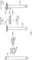
- FIG. 1 sets forth a diagram of a known sensor assembly (114) utilizing a thermal isolated fitting (TIF) tube assembly (108) formed by a brazing operation.
- a housing (104) and a braze ring (106) are added to a TIF tube (102) and blazed together during a brazing operation to create the TIF tube assembly (108).
- a welding operation is utilized to weld a disc (110) to a flange portion of the housing and weld a support ring (112) to the disc (110).
- the brazing operation creates a brazing seam between the tube (102) and the housing (104), which may lead to undesired leak paths in the sensor assembly (114).
- FIG. 2 sets forth a diagram of a sensor assembly (214) utilizing a one-piece TIF tube (202) in accordance with at least one embodiment of the present disclosure.
- the TIF tube (202) is a one-piece part that includes a cylindrical shaped body portion (203) and a flange (204) at one end of the TIF tube (202).
- the one-piece TIF tube with the flange is molded as a single piece.
- the flange (204) is a protruding circular edge surrounding the end of the TIF tube. As shown in FIG. 2 , the flange (204) has a top surface (220) that is facing away from the cylindrical shaped body portion (203). The flange (204) also has an underside surface (222) that is facing towards the cylindrical shaped body portion (203). Because the TIF (202) is formed a single piece that includes the flange (204), the housing (104), the braze ring (106), and the braze operation that are required for assembling the known sensor assembly (114) of FIG. 1 are eliminated from the sensor assembly (214) of FIG. 2 .
- the sensor assembly (214) is assembled by adding a disc (210) and a support ring (212) to a top surface (220) of the flange (204) and adding a washer (209) to an underside surface (222) of the flange (204) during a weld operation.
- the weld operation is a Tungsten Inert Gas (TIG) weld operation.
- the washer (209) provides mechanical support previously provided by the housing (104) of the known TIF tube assembly (108) of FIG. 1 .
- the sensor assembly (214) may be formed without the blazing operation, which eliminates a potential leak path in the blaze seam between the housing (104) and the TIF tube (102).
- the material used for the TIF tube (202) is a mixture of cooper and stainless steel.
- the TIF tube includes 15% copper/85% stainless steel-clad material.
- the copper is used in some embodiments where brazing is needed further down the assembly line while the stainless steel provides the strength to meet burst pressure requirements.
- Other embodiments may use different percentages of copper and stainless steel. Readers of skill in the art will realize that the material in other embodiments may be comprised of stainless steel or any other combination of suitable materials.
- FIG. 3 sets forth a diagram illustrating an exploded view of the sensor assembly (214) of FIG. 2 .
- various embodiments of the sensor assembly (214) include the disc (210) and a support ring on the top surface (220) of the flange (204) of the one-piece TIF tube (202).
- the washer (209) may be added to the underside surface (222) of the flange (204) to increase the thickness to levels necessary to avoid pressure shifts.
- a diameter of the flange (204) of the TIF tube (202) may be selected to substantially match the diameter of the housing (104) of the known TIF tube assembly (114) of FIG. 1 and a length of the TIF (202) may be selected to keep the height of the sensor assembly (214) substantially the same as the known TIF tube assembly (114) of FIG. 1 .
- the disc (210), the support ring (212), the washer (209) and the flange (204) are joined at their circumference by a weld operation, thus eliminating the brazing process described in FIG. 1 .
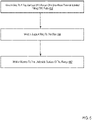
- FIG. 4 sets forth a flowchart of an example method for assembling a sensor assembly in accordance with at least one embodiment of the present disclosure.
- the method of FIG. 4 includes welding (402) a disc (210) to a top surface (220) of a flange (204) of a one-piece thermal isolated fitting (TIF) tube (202).
- the material used for the tube (202) is a mixture of copper and stainless steel-clad material. Other embodiments may use different percentages of copper and stainless steel. Readers of skill in the art will realize that the material in other embodiments may be comprised of stainless steel or any other combination of suitable materials.
- the TIF tube (202) includes a cylindrical shaped body portion having the flange (204) at one end of the TIF tube (202).
- the top surface (220) of the flange (204) faces away from the cylindrical shaped body portion (203).
- the flange (204) also has an underside surface that faces towards the cylindrical shaped body portion (203).
- Welding (402) the disc (210) to a top surface (220) of a flange (204) of a one-piece thermal isolated fitting (TIF) tube (202) may be carried out by welding the pieces together during a Tungsten Inert Gas (TIG) weld operation; and welding the circumference of the disc (210) and the circumference of the top surface (220) of the flange (204).
- TOG Tungsten Inert Gas
- the method of FIG. 4 also includes welding (404) the support ring (212) to the disc (210).
- Welding (404) the support ring (212) to the disc (210) may be carried out by welding the pieces together during a Tungsten Inert Gas (TIG) weld operation; and welding the circumference of the disc (210) and the circumference of the support ring (212).
- Tungsten Inert Gas (TIG) weld operation Tungsten Inert Gas (TIG) weld operation
- the support ring (212) is welded to the disc (210) in the same welding operation in which the disc (210) is welded to the top surface (220) of the flange (204) of the TIF tube (202).
- FIG. 5 sets forth a flowchart of another example method for assembling a sensor assembly in accordance with at least one embodiment of the present disclosure.
- the method of FIG. 5 includes the elements of the method of FIG. 4 .
- the method of FIG. 5 also includes welding (502) the washer (209) to the underside surface (222) of the flange (204).
- the washer (209) may be added to the underside surface (222) of the flange (204) to increase the thickness to levels necessary to avoid pressure shifts.
- a diameter of the flange (204) of the TIF tube (202) may be selected to substantially match the diameter of the housing (104) of the known TIF tube assembly (114) of FIG. 1 and a length of the TIF (202) may be selected to keep the height of the sensor assembly (214) substantially the same as the known TIF tube assembly (114) of FIG. 1 .
- the washer (209) is welded to the underside surface (222) in the same welding operation in which the disc (210) is welded to the top surface (220) of the flange (204) of the TIF tube (202) and the support ring (212) is welded to the disc (210).
Landscapes
- Physics & Mathematics (AREA)
- General Physics & Mathematics (AREA)
- Fluid Mechanics (AREA)
- Engineering & Computer Science (AREA)
- Manufacturing & Machinery (AREA)
- Chemical & Material Sciences (AREA)
- Analytical Chemistry (AREA)
- Measuring Fluid Pressure (AREA)
- Measuring Volume Flow (AREA)
Abstract
Description
- This application is a non-provisional application for patent entitled to a filing date and claiming the benefit of earlier-filed
U.S. Provisional Patent Application Serial No. 63/220,643, filed July 12, 2021 - Pressure switches are commonly manufactured with a thermal isolated fitting (TIF) tube assembly. The TIF tube assembly includes of a tube portion and a housing portion. In most instances, the material of the housing portion has a greater thickness than the tube portion. The difference in thickness levels between the tube and the housing precludes the manufacturing option of drawing the tube as a one-piece unit, therefore the tube portion and housing portion are typically brazed together with a braze ring to create a brazed tube assembly. This brazing process can be expensive and time consuming. Additionally, the brazing seam is susceptible to leaks and results in quality issues.
- Embodiments in accordance with the present disclosure are directed to sensor apparatuses utilizing a one-piece thermal isolated fitting (TIF) tube and methods of assembling the same. In a particular embodiment, a sensor apparatus is described that includes a one-piece thermal isolated fitting (TIF) tube that includes a cylindrical shaped body portion and a flange at one end of the TIF tube. In this example embodiment, the flange has a top surface that is facing away from the cylindrical shaped body portion and an underside surface that is facing towards the cylindrical shaped body portion.
- In another embodiment, a sensor apparatus is described that includes a one-piece thermal isolated fitting (TIF) tube having a cylindrical shaped body portion and a flange at one end of the TIF tube. In this example embodiment, the flange has a top surface that is facing away from the cylindrical shaped body portion and an underside surface that is facing towards the cylindrical shaped body portion. The sensor apparatus also includes a disc attached to the top surface of the flange and a support ring attached to the disc.
- In another embodiment, a method of assembling a sensor apparatus is described that includes welding a disc to a top surface of a flange of a one-piece thermal isolated fitting (TIF) tube. In this example embodiment, the TIF tube includes a cylindrical shaped body portion having the flange at one end of the TIF tube. The top surface of the flange is facing away from the cylindrical shaped body portion. According to this example embodiment, the flange also has an underside surface that is facing towards the cylindrical shaped body portion. In this example embodiment, the method also includes welding a support ring to the disc.
- As will be explained below, because the TIF tube of the sensor assembly described in the example embodiments is constructed and formed as a single one-piece part, the brazing operation, the housing, and the brazen ring that were required for assembling the known sensor apparatus with a TIF tube assembly may be eliminated, which also eliminates a potential leak path in the blazing seam between the housing and the TIF tube.
- The foregoing and other objects, features and advantages of the invention will be apparent from the following more particular descriptions of exemplary embodiments of the invention as illustrated in the accompanying drawings wherein like reference numbers generally represent like parts of exemplary embodiments of the invention.
- The following brief description of the drawings is meant to help one skilled in the art understand and enable the practice of various embodiments disclosed herein. It is not meant in any way to unduly limit any present or subsequent claims in or related to this application.
-
FIG. 1 sets forth a diagram of a known sensor assembly utilizing a thermal isolated fitting (TIF) tube assembly formed by a brazing operation. -
FIG. 2 sets forth a diagram of a sensor assembly utilizing a one-piece TIF tube in accordance with at least one embodiment of the present disclosure. -
FIG. 3 sets forth a diagram illustrating an exploded view of the sensor assembly ofFIG. 2 . -
FIG. 4 sets forth a flowchart of an example method for assembling a sensor assembly in accordance with at least one embodiment of the present disclosure. -
FIG. 5 sets forth a flowchart of another example method for assembling a sensor assembly in accordance with at least one embodiment of the present disclosure. - The following detailed description is meant to help one skilled in the art understand and enable the practice of various embodiments disclosed herein. It is not meant in any way to unduly limit any present or subsequent claims in or related to this application.
- The subject technology addresses many of the noted issues. The advantages, and other features of the system design disclosed herein, will become more readily apparent to those having ordinary skill in the art from the following detailed description of certain embodiments taken in conjunction with the drawings which set forth representative embodiments of the present invention and wherein like reference numerals identify similar structural elements.
- The terminology used herein for the purpose of describing particular examples is not intended to be limiting for further examples. Whenever a singular form such as "a", "an" and "the" is used and using only a single element is neither explicitly or implicitly defined as being mandatory, further examples may also use plural elements to implement the same functionality. Likewise, when a functionality is subsequently described as being implemented using multiple elements, further examples may implement the same functionality using a single element or processing entity. It will be further understood that the terms "comprises", "comprising", "includes" and/or "including", when used, specify the presence of the stated features, integers, steps, operations, processes, acts, elements and/or components, but do not preclude the presence or addition of one or more other features, integers, steps, operations, processes, acts, elements, components and/or any group thereof.
- It will be understood that when an element is referred to as being "connected" or "coupled" to another element, the elements may be directly connected or coupled via one or more intervening elements. If two elements A and B are combined using an "or", this is to be understood to disclose all possible combinations, i.e. only A, only B, as well as A and B. An alternative wording for the same combinations is "at least one of A and B". The same applies for combinations of more than two elements.
- Accordingly, while further examples are capable of various modifications and alternative forms, some particular examples thereof are shown in the figures and will subsequently be described in detail. However, this detailed description does not limit further examples to the particular forms described. Further examples may cover all modifications, equivalents, and alternatives falling within the scope of the disclosure. Like numbers refer to like or similar elements throughout the description of the figures, which may be implemented identically or in modified form when compared to one another while providing for the same or a similar functionality.
- Exemplary sensor apparatuses utilizing a one-piece thermal isolated fitting (TIF) tube and methods of assembling the same in accordance with the present disclosure are described with reference to the accompanying drawings, beginning with
FIG. 1. FIG. 1 sets forth a diagram of a known sensor assembly (114) utilizing a thermal isolated fitting (TIF) tube assembly (108) formed by a brazing operation. In the example ofFIG. 1 , a housing (104) and a braze ring (106) are added to a TIF tube (102) and blazed together during a brazing operation to create the TIF tube assembly (108). During a subsequent assembly step of the known sensor assembly (114), a welding operation is utilized to weld a disc (110) to a flange portion of the housing and weld a support ring (112) to the disc (110). As mentioned above, in this method of assembling the known sensor assembly, the brazing operation creates a brazing seam between the tube (102) and the housing (104), which may lead to undesired leak paths in the sensor assembly (114). - For further explanation,
FIG. 2 sets forth a diagram of a sensor assembly (214) utilizing a one-piece TIF tube (202) in accordance with at least one embodiment of the present disclosure. In the example ofFIG. 2 , the TIF tube (202) is a one-piece part that includes a cylindrical shaped body portion (203) and a flange (204) at one end of the TIF tube (202). In a particular embodiment, the one-piece TIF tube with the flange is molded as a single piece. - In the example of
FIG. 2 , the flange (204) is a protruding circular edge surrounding the end of the TIF tube. As shown inFIG. 2 , the flange (204) has a top surface (220) that is facing away from the cylindrical shaped body portion (203). The flange (204) also has an underside surface (222) that is facing towards the cylindrical shaped body portion (203). Because the TIF (202) is formed a single piece that includes the flange (204), the housing (104), the braze ring (106), and the braze operation that are required for assembling the known sensor assembly (114) ofFIG. 1 are eliminated from the sensor assembly (214) ofFIG. 2 . - In a particular embodiment, the sensor assembly (214) is assembled by adding a disc (210) and a support ring (212) to a top surface (220) of the flange (204) and adding a washer (209) to an underside surface (222) of the flange (204) during a weld operation. In a particular embodiment, the weld operation is a Tungsten Inert Gas (TIG) weld operation. In the example of
FIG. 2 , the washer (209) provides mechanical support previously provided by the housing (104) of the known TIF tube assembly (108) ofFIG. 1 . By utilizing a one-piece TIF tube, the sensor assembly (214) may be formed without the blazing operation, which eliminates a potential leak path in the blaze seam between the housing (104) and the TIF tube (102). - In various embodiments, the material used for the TIF tube (202) is a mixture of cooper and stainless steel. For example, in one embodiment, the TIF tube includes 15% copper/85% stainless steel-clad material. The copper is used in some embodiments where brazing is needed further down the assembly line while the stainless steel provides the strength to meet burst pressure requirements. Other embodiments may use different percentages of copper and stainless steel. Readers of skill in the art will realize that the material in other embodiments may be comprised of stainless steel or any other combination of suitable materials.
- For further explanation,
FIG. 3 sets forth a diagram illustrating an exploded view of the sensor assembly (214) ofFIG. 2 . As explained in the description ofFIG. 2 , various embodiments of the sensor assembly (214) include the disc (210) and a support ring on the top surface (220) of the flange (204) of the one-piece TIF tube (202). The washer (209) may be added to the underside surface (222) of the flange (204) to increase the thickness to levels necessary to avoid pressure shifts. - A diameter of the flange (204) of the TIF tube (202) may be selected to substantially match the diameter of the housing (104) of the known TIF tube assembly (114) of
FIG. 1 and a length of the TIF (202) may be selected to keep the height of the sensor assembly (214) substantially the same as the known TIF tube assembly (114) ofFIG. 1 . As explained above, the disc (210), the support ring (212), the washer (209) and the flange (204) are joined at their circumference by a weld operation, thus eliminating the brazing process described inFIG. 1 . - For further explanation,
FIG. 4 sets forth a flowchart of an example method for assembling a sensor assembly in accordance with at least one embodiment of the present disclosure. In the description of the method ofFIG. 4 , reference is made to the components of the sensor assembly (214) ofFIG. 2 . The method ofFIG. 4 includes welding (402) a disc (210) to a top surface (220) of a flange (204) of a one-piece thermal isolated fitting (TIF) tube (202). In various embodiments, the material used for the tube (202) is a mixture of copper and stainless steel-clad material. Other embodiments may use different percentages of copper and stainless steel. Readers of skill in the art will realize that the material in other embodiments may be comprised of stainless steel or any other combination of suitable materials. - In the example of
FIG. 4 , the TIF tube (202) includes a cylindrical shaped body portion having the flange (204) at one end of the TIF tube (202). As described above inFIG. 2 andFIG. 3 , the top surface (220) of the flange (204) faces away from the cylindrical shaped body portion (203). The flange (204) also has an underside surface that faces towards the cylindrical shaped body portion (203). Welding (402) the disc (210) to a top surface (220) of a flange (204) of a one-piece thermal isolated fitting (TIF) tube (202) may be carried out by welding the pieces together during a Tungsten Inert Gas (TIG) weld operation; and welding the circumference of the disc (210) and the circumference of the top surface (220) of the flange (204). - The method of
FIG. 4 also includes welding (404) the support ring (212) to the disc (210). Welding (404) the support ring (212) to the disc (210) may be carried out by welding the pieces together during a Tungsten Inert Gas (TIG) weld operation; and welding the circumference of the disc (210) and the circumference of the support ring (212). In a particular embodiment, the support ring (212) is welded to the disc (210) in the same welding operation in which the disc (210) is welded to the top surface (220) of the flange (204) of the TIF tube (202). - For further explanation,
FIG. 5 sets forth a flowchart of another example method for assembling a sensor assembly in accordance with at least one embodiment of the present disclosure. The method ofFIG. 5 includes the elements of the method ofFIG. 4 . In addition, the method ofFIG. 5 also includes welding (502) the washer (209) to the underside surface (222) of the flange (204). The washer (209) may be added to the underside surface (222) of the flange (204) to increase the thickness to levels necessary to avoid pressure shifts. - A diameter of the flange (204) of the TIF tube (202) may be selected to substantially match the diameter of the housing (104) of the known TIF tube assembly (114) of
FIG. 1 and a length of the TIF (202) may be selected to keep the height of the sensor assembly (214) substantially the same as the known TIF tube assembly (114) ofFIG. 1 . - Welding (502) the washer (209) to the underside surface (222) of the flange (204) welding the pieces together during a Tungsten Inert Gas (TIG) weld operation; and welding the circumference of the washer (209) and the circumference of the underside surface (222) of the flange (204). In a particular embodiment, the washer (209) is welded to the underside surface (222) in the same welding operation in which the disc (210) is welded to the top surface (220) of the flange (204) of the TIF tube (202) and the support ring (212) is welded to the disc (210).
- In view of the explanations set forth above, readers of skill in the art will recognize that the benefits of a sensor assembly that includes a one-piece TIF tube having a flange and a method of assembly the same according to embodiments of the present disclosure include, but are not limited to:
- Eliminating the brazing process utilized to couple the TIF tube to a housing portion, as described in the known sensor assembly of
FIG. 1 . - Eliminating the brazing seam between the TIF tube and a housing portion of the known sensor assembly of
FIG. 1 . - Reducing the complexity of creating a TIF tube piece having a flange for coupling with a disc and support ring.
- Aspects of the present invention are described herein with reference to flowchart illustrations and/or block diagrams of methods and apparatuses or systems according to embodiments of the invention.
- The flowchart and block diagrams in the Figures illustrate the architecture, functionality, and operation of possible implementations of systems, apparatuses, and methods according to various embodiments of the present invention. In some alternative implementations, the functions noted in the block may occur out of the order noted in the figures. For example, two blocks shown in succession may, in fact, be executed substantially concurrently, or the blocks may sometimes be executed in the reverse order, depending upon the functionality involved.
- It will be understood from the foregoing description that modifications and changes may be made in various embodiments of the present disclosure without departing from its true spirit. The descriptions in this specification are for purposes of illustration only and are not to be construed in a limiting sense. The scope of the present disclosure is limited only by the language of the following claims.
Claims (13)
- A sensor apparatus comprising:
a one-piece thermal isolated fitting (TIF) tube that includes a cylindrical shaped body portion and a flange at one end of the TIF tube; the flange having a top surface that is facing away from the cylindrical shaped body portion; the flange also having an underside surface that is facing towards the cylindrical shaped body portion. - The sensor apparatus of claim 1 further comprising:a disc welded to the top surface of the flange; anda support ring welded to the disc.
- The sensor apparatus of claim 1 further comprising a washer welded to the underside surface of the flange.
- The sensor apparatus of claim 1 wherein the one-piece TIF tube is formed as a single piece during a mold operation.
- The sensor apparatus of claim 1 wherein the one-piece TIF tube includes a combination of copper and stainless steel.
- A sensor apparatus comprising:a one-piece thermal isolated fitting (TIF) tube that includes a cylindrical shaped body portion and a flange at one end of the TIF tube; the flange having a top surface that is facing away from the cylindrical shaped body portion; the flange also having an underside surface that is facing towards the cylindrical shaped body portion;a disc attached to the top surface of the flange; anda support ring attached to the disc.
- The sensor apparatus of claim 6 comprising:
a washer attached to the underside surface of the flange. - The sensor apparatus of claim 6 wherein during a welding operation, the disc is welded to the top surface of the flange, the support ring is welded to the disc, and a washer is welded to the underside surface of the flange.
- The sensor apparatus of claim 8, wherein the welding operation is a Tungsten Inert Gas (TIG) welding operation.
- A method of assembling a sensor apparatus, the method comprising:welding a disc to a top surface of a flange of a one-piece thermal isolated fitting (TIF) tube; the TIF tube including a cylindrical shaped body portion having the flange at one end of the TIF tube; the flange having the top surface; the top surface facing away from the cylindrical shaped body portion; the flange also having an underside surface that is facing towards the cylindrical shaped body portion; andwelding a support ring to the disc.
- The method of claim 10 further comprising:
welding a washer to the underside surface of the flange. - The method of claim 10 wherein during a welding operation, the disc is welded to the top surface of the flange, the support ring is welded to the disc, and a washer is welded to the underside surface of the flange.
- The method of claim 12, wherein the welding operation is a Tungsten Inert Gas (TIG) welding operation.
Applications Claiming Priority (1)
| Application Number | Priority Date | Filing Date | Title |
|---|---|---|---|
| US202163220643P | 2021-07-12 | 2021-07-12 |
Publications (2)
| Publication Number | Publication Date |
|---|---|
| EP4119903A1 true EP4119903A1 (en) | 2023-01-18 |
| EP4119903B1 EP4119903B1 (en) | 2026-02-25 |
Family
ID=82458787
Family Applications (1)
| Application Number | Title | Priority Date | Filing Date |
|---|---|---|---|
| EP22184365.9A Active EP4119903B1 (en) | 2021-07-12 | 2022-07-12 | Sensor assemblies utilizing a one-piece thermal isolated fitting tube and methods of assembling the same |
Country Status (3)
| Country | Link |
|---|---|
| US (1) | US20230010041A1 (en) |
| EP (1) | EP4119903B1 (en) |
| CN (1) | CN115615470A (en) |
Citations (1)
| Publication number | Priority date | Publication date | Assignee | Title |
|---|---|---|---|---|
| US20100064816A1 (en) * | 2008-09-17 | 2010-03-18 | Dario Filippi | Diaphragm structure and method of manufacturing a diaphragm structure |
Family Cites Families (2)
| Publication number | Priority date | Publication date | Assignee | Title |
|---|---|---|---|---|
| FR2878306B1 (en) * | 2004-11-23 | 2007-03-16 | Legris Sa | METHOD FOR MANUFACTURING SEALING ELEMENT, SEALING ELEMENT AND CORRESPONDING CONNECTING HEAD |
| US9969608B2 (en) * | 2016-01-05 | 2018-05-15 | DunAn Sensing, LLC | Methods for mounting a MEMS sensor for in-stream measurements |
-
2022
- 2022-07-11 US US17/861,984 patent/US20230010041A1/en active Pending
- 2022-07-12 CN CN202210822415.1A patent/CN115615470A/en active Pending
- 2022-07-12 EP EP22184365.9A patent/EP4119903B1/en active Active
Patent Citations (1)
| Publication number | Priority date | Publication date | Assignee | Title |
|---|---|---|---|---|
| US20100064816A1 (en) * | 2008-09-17 | 2010-03-18 | Dario Filippi | Diaphragm structure and method of manufacturing a diaphragm structure |
Also Published As
| Publication number | Publication date |
|---|---|
| US20230010041A1 (en) | 2023-01-12 |
| EP4119903B1 (en) | 2026-02-25 |
| CN115615470A (en) | 2023-01-17 |
Similar Documents
| Publication | Publication Date | Title |
|---|---|---|
| KR20190008424A (en) | Fluid system through friction welding and its manufacturing method | |
| EP2554967B1 (en) | Pressure-sensitive device and method of welding joint of pressure-sensitive device | |
| US7181976B2 (en) | Spring-elastic measuring element comprising a flat connecting element that can be welded | |
| JP2017129206A (en) | Electric drive valve and process of manufacturing the same | |
| EP4119903B1 (en) | Sensor assemblies utilizing a one-piece thermal isolated fitting tube and methods of assembling the same | |
| JP4640551B2 (en) | Method for manufacturing fluid pressure device | |
| CN101012937A (en) | Manufacture of a combustion chamber | |
| EP1602870A1 (en) | Tube to hose coupling | |
| US20160238326A1 (en) | Header tank of heat exchanger and heat exchanger having the same | |
| EP2614914B1 (en) | A fuel nozzle and process of fabricating a fuel nozzle | |
| CN116073212A (en) | Method for producing an electrical feed-through | |
| JP2004090877A (en) | Fuel feed pipe | |
| JP2005088048A (en) | Welding strain absorbing flange for pipe joint and pipe joint | |
| US20190275601A1 (en) | Method for manufacturing solenoid sleeve | |
| US7883782B2 (en) | Three components linked to each other by means of a welded connection | |
| US6478213B1 (en) | Fluxless fabrication of a multi-tubular structure | |
| US11293823B2 (en) | Method for producing a pressure transmitter system | |
| US12007049B2 (en) | Method for producing a pipeline arrangement, and pipeline arrangement | |
| CN110653469B (en) | Joining device and joining method | |
| WO2019107062A1 (en) | Pipe joint and pipe connection method | |
| JP5000617B2 (en) | Piping measuring instrument mounting structure | |
| EP0095284A1 (en) | Tantalum bonding method | |
| CN108223875B (en) | fluid housing | |
| JP2007301577A (en) | Cylindrical product | |
| CN110345319A (en) | A kind of pipe fitting joint structure, a kind of muffler, a kind of air-conditioning system and a kind of refrigeration system |
Legal Events
| Date | Code | Title | Description |
|---|---|---|---|
| PUAI | Public reference made under article 153(3) epc to a published international application that has entered the european phase |
Free format text: ORIGINAL CODE: 0009012 |
|
| STAA | Information on the status of an ep patent application or granted ep patent |
Free format text: STATUS: THE APPLICATION HAS BEEN PUBLISHED |
|
| AK | Designated contracting states |
Kind code of ref document: A1 Designated state(s): AL AT BE BG CH CY CZ DE DK EE ES FI FR GB GR HR HU IE IS IT LI LT LU LV MC MK MT NL NO PL PT RO RS SE SI SK SM TR |
|
| STAA | Information on the status of an ep patent application or granted ep patent |
Free format text: STATUS: REQUEST FOR EXAMINATION WAS MADE |
|
| 17P | Request for examination filed |
Effective date: 20230711 |
|
| P01 | Opt-out of the competence of the unified patent court (upc) registered |
Effective date: 20230708 |
|
| RBV | Designated contracting states (corrected) |
Designated state(s): AL AT BE BG CH CY CZ DE DK EE ES FI FR GB GR HR HU IE IS IT LI LT LU LV MC MK MT NL NO PL PT RO RS SE SI SK SM TR |
|
| STAA | Information on the status of an ep patent application or granted ep patent |
Free format text: STATUS: EXAMINATION IS IN PROGRESS |
|
| 17Q | First examination report despatched |
Effective date: 20240328 |
|
| GRAP | Despatch of communication of intention to grant a patent |
Free format text: ORIGINAL CODE: EPIDOSNIGR1 |
|
| STAA | Information on the status of an ep patent application or granted ep patent |
Free format text: STATUS: GRANT OF PATENT IS INTENDED |
|
| INTG | Intention to grant announced |
Effective date: 20250925 |
|
| GRAS | Grant fee paid |
Free format text: ORIGINAL CODE: EPIDOSNIGR3 |
|
| GRAA | (expected) grant |
Free format text: ORIGINAL CODE: 0009210 |
|
| STAA | Information on the status of an ep patent application or granted ep patent |
Free format text: STATUS: THE PATENT HAS BEEN GRANTED |
|
| AK | Designated contracting states |
Kind code of ref document: B1 Designated state(s): AL AT BE BG CH CY CZ DE DK EE ES FI FR GB GR HR HU IE IS IT LI LT LU LV MC MK MT NL NO PL PT RO RS SE SI SK SM TR |
|
| REG | Reference to a national code |
Ref country code: CH Ref legal event code: F10 Free format text: ST27 STATUS EVENT CODE: U-0-0-F10-F00 (AS PROVIDED BY THE NATIONAL OFFICE) Effective date: 20260225 Ref country code: GB Ref legal event code: FG4D |
|
| REG | Reference to a national code |
Ref country code: DE Ref legal event code: R096 Ref document number: 602022030977 Country of ref document: DE |
|
| REG | Reference to a national code |
Ref country code: IE Ref legal event code: FG4D |