EP4119868B1 - Lebensmittel-kältemaschine - Google Patents
Lebensmittel-kältemaschine Download PDFInfo
- Publication number
- EP4119868B1 EP4119868B1 EP22183407.0A EP22183407A EP4119868B1 EP 4119868 B1 EP4119868 B1 EP 4119868B1 EP 22183407 A EP22183407 A EP 22183407A EP 4119868 B1 EP4119868 B1 EP 4119868B1
- Authority
- EP
- European Patent Office
- Prior art keywords
- heat exchanger
- pressure
- refrigerant
- low
- supplementary
- Prior art date
- Legal status (The legal status is an assumption and is not a legal conclusion. Google has not performed a legal analysis and makes no representation as to the accuracy of the status listed.)
- Active
Links
Images


Classifications
-
- F—MECHANICAL ENGINEERING; LIGHTING; HEATING; WEAPONS; BLASTING
- F25—REFRIGERATION OR COOLING; COMBINED HEATING AND REFRIGERATION SYSTEMS; HEAT PUMP SYSTEMS; MANUFACTURE OR STORAGE OF ICE; LIQUEFACTION SOLIDIFICATION OF GASES
- F25D—REFRIGERATORS; COLD ROOMS; ICE-BOXES; COOLING OR FREEZING APPARATUS NOT OTHERWISE PROVIDED FOR
- F25D11/00—Self-contained movable devices, e.g. domestic refrigerators
-
- F—MECHANICAL ENGINEERING; LIGHTING; HEATING; WEAPONS; BLASTING
- F25—REFRIGERATION OR COOLING; COMBINED HEATING AND REFRIGERATION SYSTEMS; HEAT PUMP SYSTEMS; MANUFACTURE OR STORAGE OF ICE; LIQUEFACTION SOLIDIFICATION OF GASES
- F25B—REFRIGERATION MACHINES, PLANTS OR SYSTEMS; COMBINED HEATING AND REFRIGERATION SYSTEMS; HEAT PUMP SYSTEMS
- F25B40/00—Subcoolers, desuperheaters or superheaters
-
- F—MECHANICAL ENGINEERING; LIGHTING; HEATING; WEAPONS; BLASTING
- F25—REFRIGERATION OR COOLING; COMBINED HEATING AND REFRIGERATION SYSTEMS; HEAT PUMP SYSTEMS; MANUFACTURE OR STORAGE OF ICE; LIQUEFACTION SOLIDIFICATION OF GASES
- F25B—REFRIGERATION MACHINES, PLANTS OR SYSTEMS; COMBINED HEATING AND REFRIGERATION SYSTEMS; HEAT PUMP SYSTEMS
- F25B2700/00—Sensing or detecting of parameters; Sensors therefor
- F25B2700/19—Pressures
- F25B2700/193—Pressures of the compressor
- F25B2700/1931—Discharge pressures
-
- F—MECHANICAL ENGINEERING; LIGHTING; HEATING; WEAPONS; BLASTING
- F25—REFRIGERATION OR COOLING; COMBINED HEATING AND REFRIGERATION SYSTEMS; HEAT PUMP SYSTEMS; MANUFACTURE OR STORAGE OF ICE; LIQUEFACTION SOLIDIFICATION OF GASES
- F25B—REFRIGERATION MACHINES, PLANTS OR SYSTEMS; COMBINED HEATING AND REFRIGERATION SYSTEMS; HEAT PUMP SYSTEMS
- F25B2700/00—Sensing or detecting of parameters; Sensors therefor
- F25B2700/19—Pressures
- F25B2700/193—Pressures of the compressor
- F25B2700/1933—Suction pressures
-
- F—MECHANICAL ENGINEERING; LIGHTING; HEATING; WEAPONS; BLASTING
- F25—REFRIGERATION OR COOLING; COMBINED HEATING AND REFRIGERATION SYSTEMS; HEAT PUMP SYSTEMS; MANUFACTURE OR STORAGE OF ICE; LIQUEFACTION SOLIDIFICATION OF GASES
- F25B—REFRIGERATION MACHINES, PLANTS OR SYSTEMS; COMBINED HEATING AND REFRIGERATION SYSTEMS; HEAT PUMP SYSTEMS
- F25B2700/00—Sensing or detecting of parameters; Sensors therefor
- F25B2700/21—Temperatures
- F25B2700/2115—Temperatures of a compressor or the drive means therefor
- F25B2700/21151—Temperatures of a compressor or the drive means therefor at the suction side of the compressor
-
- F—MECHANICAL ENGINEERING; LIGHTING; HEATING; WEAPONS; BLASTING
- F25—REFRIGERATION OR COOLING; COMBINED HEATING AND REFRIGERATION SYSTEMS; HEAT PUMP SYSTEMS; MANUFACTURE OR STORAGE OF ICE; LIQUEFACTION SOLIDIFICATION OF GASES
- F25B—REFRIGERATION MACHINES, PLANTS OR SYSTEMS; COMBINED HEATING AND REFRIGERATION SYSTEMS; HEAT PUMP SYSTEMS
- F25B2700/00—Sensing or detecting of parameters; Sensors therefor
- F25B2700/21—Temperatures
- F25B2700/2115—Temperatures of a compressor or the drive means therefor
- F25B2700/21152—Temperatures of a compressor or the drive means therefor at the discharge side of the compressor
-
- F—MECHANICAL ENGINEERING; LIGHTING; HEATING; WEAPONS; BLASTING
- F25—REFRIGERATION OR COOLING; COMBINED HEATING AND REFRIGERATION SYSTEMS; HEAT PUMP SYSTEMS; MANUFACTURE OR STORAGE OF ICE; LIQUEFACTION SOLIDIFICATION OF GASES
- F25B—REFRIGERATION MACHINES, PLANTS OR SYSTEMS; COMBINED HEATING AND REFRIGERATION SYSTEMS; HEAT PUMP SYSTEMS
- F25B9/00—Compression machines, plants or systems, in which the refrigerant is air or other gas of low boiling point
- F25B9/002—Compression machines, plants or systems, in which the refrigerant is air or other gas of low boiling point characterised by the refrigerant
- F25B9/008—Compression machines, plants or systems, in which the refrigerant is air or other gas of low boiling point characterised by the refrigerant the refrigerant being carbon dioxide
-
- F—MECHANICAL ENGINEERING; LIGHTING; HEATING; WEAPONS; BLASTING
- F25—REFRIGERATION OR COOLING; COMBINED HEATING AND REFRIGERATION SYSTEMS; HEAT PUMP SYSTEMS; MANUFACTURE OR STORAGE OF ICE; LIQUEFACTION SOLIDIFICATION OF GASES
- F25D—REFRIGERATORS; COLD ROOMS; ICE-BOXES; COOLING OR FREEZING APPARATUS NOT OTHERWISE PROVIDED FOR
- F25D2400/00—General features of, or devices for refrigerators, cold rooms, ice-boxes, or for cooling or freezing apparatus not covered by any other subclass
- F25D2400/28—Quick cooling
-
- F—MECHANICAL ENGINEERING; LIGHTING; HEATING; WEAPONS; BLASTING
- F25—REFRIGERATION OR COOLING; COMBINED HEATING AND REFRIGERATION SYSTEMS; HEAT PUMP SYSTEMS; MANUFACTURE OR STORAGE OF ICE; LIQUEFACTION SOLIDIFICATION OF GASES
- F25D—REFRIGERATORS; COLD ROOMS; ICE-BOXES; COOLING OR FREEZING APPARATUS NOT OTHERWISE PROVIDED FOR
- F25D2400/00—General features of, or devices for refrigerators, cold rooms, ice-boxes, or for cooling or freezing apparatus not covered by any other subclass
- F25D2400/30—Quick freezing
Definitions
- the present invention relates to a refrigerating machine for food products.
- the present invention relates to a blast chiller for food products of a professional type particularly suitable for use in the kitchens of restaurants, canteens, pastry shops and the like. Appliance to which the following disclosure will explicitly refer without thereby losing generality.
- the foodstuff blast chillers are appliances capable of quickly cooling and/or freezing foods and other foodstuff products, even as soon as they have been taken out of the oven, while simultaneously preserving the fragrance, the compactness, the colours and the nutritional values thereof, and more generally all the organoleptic properties.
- These professional appliances comprise: an outer boxlike casing, generally substantially parallelepiped in shape and with a self-supporting structure, which is usually made of stainless steel and is provided, on the inside, with a large, substantially parallelepiped-shape, storage chamber or compartment that is suitably thermo-insulated so as to minimise the heat exchange with the outside, is adapted to contain the foodstuff to be treated, and communicates with the outside through a large access opening located on the front face of the boxlike casing; a substantially rectangular -shaped, large door with thermo-insulating structure, which is flag hinged to the outer casing so as to be movable about a vertical axis to and from a closed position, in which the door rests on the front face of the casing in order to more or less hermetically close the access opening to the inner thermo-insulated compartment; and an electrically-operated heat-pump cooling circuit which is capable of cooling down what is contained inside the thermo-insulated compartment.
- blast chillers are provided with an electronic control unit that drives the heat pump cooling circuit so as to bring, in a predetermined and relatively short time interval, the product contained into the thermo-insulated compartment to a given target temperature usually ranging between -18°C and +3°C, following a predetermined cooling curve that depends on the type of food contained at the moment in the thermo-insulated compartment.
- the target temperatures of the cooling process and the relative times are determined by the in-force regulations on hygiene and food safety.
- the heat pump cooling circuit in order to quickly cool the food even when it is still at a high temperature and to prevent the formation of ice macro-crystals inside the product, the heat pump cooling circuit must provide performances (cooling capacity) that, with equal storage volume, is significantly higher than the typical performances of traditional refrigerators or freezers.
- the heat pump cooling circuit must also be structured so as to allow the electronic control unit to vary/adjust, albeit in an approximate manner, the temperature of the air that circulates inside the thermo-insulated compartment and skims the food.
- DE102019210540 A1 discloses a household refrigerating appliance according to the preamble of claim 1.
- Aim of the present invention is to manufacture a heat pump circuit for professional blast chillers which, on equal efficiency and performances, uses a refrigerant with a lower environmental impact.
- a foodstuff refrigerating machine as defined in Claim 1 and preferably, though not necessarily, in any one of the claims dependent thereon.
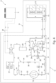
- reference number 1 denotes, as a whole, a foodstuff refrigerating machine which is capable of rapidly cooling and/or freezing foods and other foodstuff products, also still hot, preferably so as to preserve the fragrance, the compactness, the colours and, more generally, the organoleptic properties of the foodstuff product.
- the refrigerating machine 1 finds particularly advantageous use in the kitchens of restaurants, canteens, pastry shops and the like.
- the refrigerating machine 1 is preferably adapted to bring, in a predetermined and relatively short time interval (generally 90-240 minutes), the foods or other foodstuff products placed inside it to a given target temperature generally ranging between -40°C and +40°C, preferably while following a predetermined cooling curve that depends on the temperature and/or on the type of food contained at that moment inside the refrigerating machine 1.
- the refrigeration machine 1 is preferably a professional foodstuff blast chiller that can be advantageously used to quickly freeze foods and other foodstuff products, even when still hot, counteracting bacterial growth and preventing formation of ice macro-crystals inside the product.
- the refrigerating machine 1 firstly comprises: an outer boxlike casing 2, preferably with a rigid self-supporting structure and preferably substantially parallelepiped in shape, which is provided on the inside with a large, preferably substantially parallelepiped in shape, storage chamber or compartment 3 that is suitably thermo-insulated so as to minimise the heat exchange with the outside, is adapted to contain the foodstuff products to be subjected to rapid cooling, and communicates with the outside through a large access opening 4 that is preferably located on the front face of the outer casing 2; and a movable door 5 with thermo-insulating structure, which is adapted to close the access opening 4 preferably substantially hermetically.
- the door 5 is preferably hinged to the outer casing 2 so as to be able to freely rotate to and from a closed position (see Figures 1 and 2 ) in which the door 5 closes the access opening 4 to the thermo-insulated compartment 3 preferably substantially hermetically.
- the boxlike casing 2 and the thermo-insulated compartment 3 are preferably substantially rectangular parallelepiped in shape, and the thermo-insulated compartment 3 preferably communicates with the outside through an access opening 4 substantially rectangular in shape.
- the door 5, on the other hand, preferably has a substantially rectangular plate-like structure, and is preferably flag hinged to the front face of the boxlike casing 2 so as to be able to rotate about a substantially vertical rotation axis A, to and from a closed position (see Figures 1 and 2 ) in which the door 5 rests on the front face of the boxlike casing 2 and closes, preferably substantially hermetically, the access opening 4 to the thermo-insulated compartment 3.
- the refrigerating machine 1 moreover comprises: an electrically-operated cooling assembly 6, which is adapted to cool down what is contained inside the thermo-insulated compartment 3 and is preferably also at least partially accommodated inside of the boxlike casing 2; and an electronic control unit 7 which is preferably located outside of the boxlike casing 2, and is adapted to command the cooling assembly 6 preferably depending on the signals coming from one or more temperature sensors (not visible in the figures) that are adapted to detect, continuously or at regular intervals, the temperature inside the thermo-insulated compartment 3.
- an electrically-operated cooling assembly 6 which is adapted to cool down what is contained inside the thermo-insulated compartment 3 and is preferably also at least partially accommodated inside of the boxlike casing 2
- an electronic control unit 7 which is preferably located outside of the boxlike casing 2, and is adapted to command the cooling assembly 6 preferably depending on the signals coming from one or more temperature sensors (not visible in the figures) that are adapted to detect, continuously or at regular intervals, the temperature inside the thermo-insulated compartment 3.
- the electronic control unit 7 is preferably also adapted to control the cooling assembly 6 depending on the signals coming from one or more portable temperature probes (not visible in the figures) that are adapted to detect, continuously or at regular intervals, the temperature inside the food or other foodstuff temporarily located inside the thermo-insulated compartment 3.
- the electronic control unit 7 is adapted to drive the cooling assembly 6 so as to bring, in a given time interval preferably, though not necessarily, ranging between 60 and 240 minutes, the temperature measured inside of the thermo-insulated compartment 3 to a predetermined target value preferably ranging between -40°C and +40°C, preferably also causing the temperature of the food or other foodstuff inside the thermo-insulated compartment 3 to reach the target temperature following a cooling curve of predetermined shape.
- the target temperature and the cooling curve depend on the type of food or other foodstuff present in the thermo-insulated compartment 3 and its initial temperature.
- the value of the target temperature, the time to reach the target temperature and, preferably, also the time course of the temperature inside the thermo-insulated compartment 3 up to the target temperature, i.e. the cooling curve, depend(s) on the type of foodstuff product contained at the moment inside the thermo-insulated compartment 3, and are preferably adapted to preserve the organoleptic properties of the foodstuff product.
- the value of the target temperature and/or the time to reach the target temperature and/or the cooling curve up to the target temperature is/are moreover manually selected/selectable by the user through a control panel 8 preferably located outside of the boxlike casing 2.
- the control panel 8 may also be located on the external face of the door 5.
- the electronic control unit 7 is preferably provided with a non-volatile memory where a series of target temperatures, the times for reaching the same target temperature, and a series of cooling curves up to target temperature are stored, each of which is uniquely associated with a type of food; and the user can select the desired target temperature and the time to reach the same target temperature via the control panel 8.
- the cooling assembly 6 in turn comprises a heat pump unit 10 and a source of refrigerated water at a substantially constant temperature preferably ranging between +4°C and +12°C, which cooperates with the heat pump unit 10 so as to cool down what contained into the thermo-insulated compartment 3.
- the refrigerated water source is furthermore an electrically-operated hydronic unit 11 which is completely separate and independent from the heat pump unit 10, and is structured so as to supply the heat pump unit 10 with a more or less constant flow of refrigerated water with a substantially constant temperature preferably ranging between +4°C and +12°C.
- the auxiliary hydronic unit 11 is moreover entirely located outside of the boxlike casing 2.
- the electronic control unit 7 is adapted to command the heat pump unit 10 and preferably also the auxiliary hydronic unit 11.
- the cooling circuit of the heat pump unit 10 comprises: a first heat exchanger 12, traditionally called high-pressure heat exchanger or condenser, where the high-pressure refrigerant cools down preferably up to totally passing to the liquid state; a second heat exchanger 13, traditionally called low-pressure heat exchanger or evaporator, where the low-pressure refrigerant heats up preferably to totally passing to the gaseous state; a preferably electrically-operated, gas expansion device 14 which is interposed between the outlet of the high-pressure heat exchanger 12 and the inlet of the low-pressure heat exchanger 13, and is adapted to cause the rapid and irreversible expansion of the refrigerant that flows from the outlet of heat exchanger 12 towards the inlet of heat exchanger 13, so that the refrigerant entering into the heat exchanger 13 has pressure and temperature significantly lower than those of the refrigerant coming out of the heat exchanger 12; and an electrically-operated compressor 15 which is interposed between the heat exchangers 12 and 13, and
- the high-pressure heat exchanger 12 in addition, is located outside of the thermo-insulated compartment 3 and preferably also outside of the boxlike casing 2, and is hydraulically connected to the refrigerated water source 11 so that the refrigerated water flow coming from the refrigerated water source 11 removes heat from the refrigerant.
- the refrigerated water inlet and outlet of the auxiliary hydronic unit 11 are connected to the high-pressure heat exchanger 12, so as to circulate the refrigerated water inside the heat exchanger 12.
- the heat exchanger 13 is preferably located inside the thermo-insulated compartment 3, and is adapted to be skimmed/passed through by the air present/ circulating inside the thermo-insulated compartment 3 so that the air of the thermo-insulated compartment 3 releases heat to the refrigerant.
- the gas expansion device 14 is preferably located outside of the thermo-insulated compartment 3, whereas the compressor 15 is located outside of the thermo-insulated compartment 3 and preferably also outside of the boxlike casing 2.
- the cooling circuit of heat pump unit 10 moreover uses gas R744 (carbon dioxide) as refrigerant.
- the electronic control unit 7 commands the compressor 15 and, preferably, also the gas expansion device 14, on the basis of the signals coming from the temperature sensor(s) and/or from the portable temperature probe(s) (not visible in the figures).
- the electronic control unit 7 commands the switching on and off of the compressor 15 depending on the signals coming from the temperature sensor(s) and/or the temperature probe(s).
- the high-pressure heat exchanger 12 is preferably a plate heat exchanger.
- the low-pressure heat exchanger 13 is preferably a finned-pack heat exchanger.
- the heat pump unit 10 is moreover provided with one or more electrically-operated fans that are located on the finned-pack heat exchanger and are adapted to produce an air flow that skims and/or passes through the heat exchanger.
- the electronic control unit 7 is preferably adapted to activate and deactivate said fan(s) on the basis of the signals coming from the temperature sensor(s) and/or from the portable temperature probe(s) (not visible in the figures) .
- the gas expansion device 14, is preferably an electrically-operated lamination valve of known type, whereas the compressor 15 is preferably a positive-displacement piston compressor of known type.
- the cooling circuit of heat pump unit 10 moreover comprises a supplementary heat exchanger 16, which is preferably located outside of the thermo-insulated compartment 3 and more conveniently outside of the boxlike casing 2, and is adapted to transfer heat from the high-pressure refrigerant directed towards the gas expansion device 14, to the low-pressure refrigerant directed towards the intake of compressor 15, so as to bring to the gaseous state substantially the whole refrigerant directed towards the compressor 15.
- a supplementary heat exchanger 16 which is preferably located outside of the thermo-insulated compartment 3 and more conveniently outside of the boxlike casing 2, and is adapted to transfer heat from the high-pressure refrigerant directed towards the gas expansion device 14, to the low-pressure refrigerant directed towards the intake of compressor 15, so as to bring to the gaseous state substantially the whole refrigerant directed towards the compressor 15.
- the heat exchanger 16 is provided with a high-pressure branch and a low-pressure branch.
- the high-pressure branch of the supplementary heat exchanger 16 is interposed between the outlet of the high-pressure heat exchanger 12 and the gas expansion device 14.
- the low-pressure branch of the supplementary heat exchanger 16 is interposed between the outlet of the low-pressure heat exchanger 13 and the intake of compressor 15.
- the supplementary heat exchanger 16 is preferably a plate heat exchanger.
- the cooling circuit of the heat pump unit 10 moreover comprises a draw-off line 17, which is selectively adapted to divert, towards the inlet of the low-pressure branch of heat exchanger 16, a small part of the high-pressure refrigerant coming out of the high-pressure branch of heat exchanger 16, bypassing the low-pressure heat exchanger 13.
- the draw-off line 17 is at the same time adapted to subject the refrigerant that flows along the draw-off line 17 directed towards the low-pressure branch of the supplementary heat exchanger 16, to a rapid and irreversible expansion so as to drastically reduce the temperature and pressure values.
- the draw-off line 17 is moreover controlled by the electronic control unit 7.
- the electronic control unit 7 is preferably adapted to activate and deactivate the draw-off line 17 on the basis of the temperature and/or pressure values of the refrigerant measured immediately upstream and/or immediately downstream of compressor 15.
- the electronic control unit 7 is moreover adapted to command the draw-off line 17, so as to vary/ adjust, in real time, the flowrate of the refrigerant directed towards the low-pressure branch of heat exchanger 16, bypassing the heat exchanger 13.
- the draw-off line 17 preferably comprises: a supplementary pipe 18 that branches off from the pipeline 19 that puts the outlet of the high-pressure branch of the supplementary heat exchanger 16 into communication with the gas expansion device 14, and ends at the inlet of the low-pressure branch of heat exchanger 16, so as to divert/channel, towards the low-pressure branch of the heat exchanger 16, a small part of the high-pressure refrigerant coming out of the high-pressure branch of heat exchanger 16 directed towards the heat exchanger 13; an electrically-operated control valve 20 which is located along the supplementary pipe 18 and is adapted to adjust the flow of the refrigerant directed towards the low-pressure branch of heat exchanger 16; and a lamination member 21 that is located along the supplementary pipe 18 and causes the rapid and irreversible expansion of the refrigerant that flows along the supplementary pipe 18, so as to reduce the pressure and the temperature of the refrigerant directed towards the low-pressure branch of heat exchanger 16.
- the lamination member 21 is preferably a capillary tube of known type.
- the control valve 20, on the other hand, is preferably structured so as to vary/adjust the flowrate of the refrigerant flowing along pipe 18.
- the electronic control unit 7 is adapted to open and close the control valve 20 on the basis of the temperature and/or pressure values of the refrigerant measured immediately upstream and/or immediately downstream of compressor 15.
- the electronic control unit 7 is moreover adapted to command the control valve 20, so as to vary/adjust the flowrate of the refrigerant directed towards the low-pressure branch of the supplementary heat exchanger 16.
- the heat pump unit 10 is preferably provided with a temperature and/or pressure sensor 22 that is located immediately downstream of the delivery of compressor 15, and/or a temperature and/or pressure sensor 23 which is located immediately upstream of the intake of compressor 15.
- the electronic control unit 7 is preferably electronically connected to the temperature and/or pressure sensor(s) 22 and/or 23, and is adapted to drive the control valve 20 on the basis of the signals coming from said temperature and/or pressure sensor(s) 22 and/or 23.
- the electronic control unit 7 is preferably programmed/configured so as to open the control valve 20 when the temperature of the refrigerant flowing out of the compressor 15 exceeds a first limit value preferably greater than or equal to +100°C.
- the electronic control unit 7 is preferably programmed/configured so as to open the control valve 20 when the temperature of the refrigerant entering into the compressor 15 exceeds a second limit value preferably greater than or equal to +20°C.
- the electronic control unit 7 is furthermore programmed/configured so to close the control valve 20 when the temperature of the refrigerant entering and/or leaving the compressor 15 is lower than said first and/or second limit value.
- the cooling circuit of heat pump unit 10 additionally comprises: a gas-liquid separator, which is located immediately upstream of the inlet of the low-pressure branch of supplementary heat exchanger 16, so as to be crossed by the refrigerant directed towards the inlet of the low-pressure branch of supplementary heat exchanger 16, and is adapted to separate the gaseous-state refrigerant from the liquid-state refrigerant while diverting the prevailing part of the gaseous-state refrigerant towards a secondary outlet of the same gas-liquid separator; and an auxiliary pipe that connects the secondary outlet of the gas-liquid separator to the pipeline that puts the outlet of the low-pressure branch of heat exchanger 16 into communication with the intake of compressor 15.
- a gas-liquid separator which is located immediately upstream of the inlet of the low-pressure branch of supplementary heat exchanger 16, so as to be crossed by the refrigerant directed towards the inlet of the low-pressure branch of supplementary heat exchanger 16, and is adapted to separate the gaseous-state refrigerant from the liquid-state
- the draw-off line 17 is preferably connected to the inlet of the low-pressure branch of supplementary heat exchanger 16, via the interposition of the gas-liquid separator.
- the cooling circuit of heat pump unit 10 is provided with a bypass line 24, which is arranged in parallel with the low-pressure branch of the supplementary heat exchanger 16, and is adapted to divert at least part of only the gaseous-state refrigerant directly towards the intake of compressor 15, bypassing the low-pressure branch of the heat exchanger 16.
- the by-pass line 24 is preferably interposed between the inlet of the low-pressure branch of supplementary heat exchanger 16 and the intake of compressor 15, and is adapted to divert, towards the intake of compressor 15, at least a part of the gaseous-state refrigerant that comes from the heat exchanger 13 and/or from the draw-off line 17 and is directed towards the inlet of the low-pressure branch of the heat exchanger 16, while instead letting the whole liquid-state refrigerant flow inside the low-pressure branch of supplementary heat exchanger 16.
- the bypass line 24 preferably comprises: a gas-liquid separator 25, which is located immediately upstream of the inlet of the low-pressure branch of supplementary heat exchanger 16 so as to be crossed by the refrigerant coming from the heat exchanger 13 and/or from the draw-off line 17, and is adapted to separate the gaseous-state refrigerant from the liquid-state refrigerant and to divert the major part of the gaseous-state refrigerant towards a secondary outlet of the same gas-liquid separator 25; a static or dynamic three-way mixing member 26 which is located along the pipeline 27 that puts the outlet of the low-pressure branch of heat exchanger 16 into communication with the intake of compressor 15; and an auxiliary pipe 28 that connects the secondary outlet of the gas-liquid separator 25 to the mixing member 26, so as to convey the gaseous-state refrigerant to the mixing member 26 and introduce the refrigerant into the pipeline 27, downstream of the supplementary heat exchanger 16.
- a gas-liquid separator 25 which is located immediately upstream of the inlet of the low
- the three-way mixing member 26 is adapted to channel, towards the intake of compressor 15, both the gaseous-state refrigerant coming from the outlet of the low-pressure branch of supplementary heat exchanger 16, and the gaseous-state refrigerant coming from the gas-liquid separator 25.
- the mixing member 26 is moreover structured so as to be able to adjust/vary the amount of gaseous-state refrigerant coming from the gas-liquid separator 25 and the amount of gaseous-state refrigerant coming from the low-pressure branch of heat exchanger 16.
- the mixing member 26 preferably consists of an electrically-operated three-way mixing valve that is preferably controlled by the electronic control unit 7, and is able to adjust/vary the ratio between the flowrate of the gaseous-state refrigerant coming from the gas-liquid separator 25, and the flowrate of the gaseous-state refrigerant coming from the low-pressure branch of heat exchanger 16.
- the mixing member 26 may also consist of a manually-operated three-way mixing valve.
- the fraction of refrigerant coming from the gas-liquid separator 25 and the fraction of refrigerant coming from the heat exchanger 16 are manually adjusted by the technician.
- the cooling circuit of heat pump unit 10 preferably moreover comprises a pressurized tank 29, which has a nominal capacity preferably ranging between 1 and 100 litres, and is located between the outlet of the high-pressure heat exchanger 12 and the inlet of the high-pressure branch of supplementary heat exchanger 16, so as to be able to accumulate a given amount of liquid- and/or gaseous- state refrigerant coming from the high-pressure heat exchanger 12.
- the cooling circuit of heat pump unit 10 is additionally provided with a filtering member 30, which is located along the pipeline 27 connecting the outlet of the low-pressure branch of supplementary heat exchanger 16 to the intake of compressor 15, preferably immediately downstream of mixing member 26, and is adapted to retain the impurities present in the flow of refrigerant directed towards the intake of compressor 15.
- the cooling circuit of heat pump unit 10 preferably also comprises an auxiliary heat-exchanger 31 that is located between the delivery of the compressor 15 and the inlet of the high-pressure heat exchanger 12, and is adapted to cool down the high-pressure refrigerant directed towards the heat exchanger 12.
- the auxiliary heat exchanger 31 is furthermore located outside of the thermo-insulated compartment 3, and is adapted to be skimmed/crossed by the air present outside of the refrigerating machine 1, so that the external air removes heat from the high-pressure refrigerant.
- the auxiliary heat exchanger 31 is preferably a finned-pack heat exchanger and is preferably located outside the boxlike casing 3.
- the heat pump unit 10 is additionally provided with one or more electrically-operated fans (not visible in the figures) that are located on the finned-pack heat exchanger and are adapted to produce an air flow that skims and/or crosses the heat exchanger.
- the electronic control unit 7, in addition, is preferably adapted to activate and deactivate the fan or fans of the auxiliary heat exchanger 31 on the basis of some operating parameters of the refrigerating machine 1.
- the electronic control unit 7 is preferably adapted to activate and deactivate the fan or fans of auxiliary heat exchanger 31 on the basis of the refrigerant temperature detected immediately downstream of the auxiliary heat exchanger 31 and/or of the outside air.
- the electronic control unit 7 is preferably adapted to activate and deactivate the fan or fans of auxiliary heat exchanger 31 on the basis of the signals coming from a temperature sensor present on the auxiliary heat exchanger 31.
- the cooling circuit of heat pump unit 10 furthermore includes an oil recovery line 32, which connects the delivery of compressor 15 to the intake of the same compressor 15, and is adapted to retain and channel again towards the intake of compressor 15 most of the oil drops that are suspended in the high-pressure refrigerant flowing out of compressor 15.
- the oil recovery line 32 preferably comprises: an oil separator 33, which is located downstream of the delivery of compressor 15 so as to be crossed by the refrigerant directed towards the high-pressure heat exchanger 12, and is adapted to retain the oil drops in suspension in the refrigerant; a return pipe 34 that connects the oil outlet of the oil separator 33 to the intake of compressor 15, so as to direct/ channel the oil accumulating into the oil separator 33, again towards the intake of compressor 15; an electrically-operated shut-off valve 35, which is located along pipe 34 and is adapted to adjust the oil flow towards the intake of compressor 15; and optionally also a second filtering member 36, which is located along the pipe 34, upstream of the shut-off valve 35, and is adapted to retain the impurities present in the oil directed towards the intake of compressor 15.
- the liquid oil that accumulates in the oil separator 33 is pushed towards the intake of compressor 15 by the difference in pressure existing between the delivery and the intake of compressor 15.
- the electronic control unit 7, in addition, is preferably adapted to also control the shut-off valve 35, so as to introduce, preferably at more or less regular intervals, small amounts of oil into the flow of low-pressure refrigerant entering into the compressor 15.
- the cooling circuit of heat pump unit 10 is furthermore provided with a non-return valve 37 which is located between the delivery of compressor 15 and the high-pressure heat exchanger 12, and is oriented so as to allow the refrigerant to flow exclusively in direction of heat exchanger 12.
- the heat pump unit 10 is finally divided into an evaporating module and a condensing module, suitably connected by means of specific pipes.
- the evaporating module of heat pump unit 10 comprises the low-pressure heat exchanger 13 and the gas expansion device 14, and is preferably located inside the thermo-insulated compartment 3.
- the condensing module of heat pump unit 10 comprises the high-pressure heat exchanger 12, the compressor 15, the supplementary heat exchanger 16, the draw-off line 17, the bypass line 24, the pressurized tank 29, the auxiliary heat exchanger 31, if present, and the remaining components of the cooling circuit of heat pump unit 10, and is preferably located on an easily transportable self-supporting structure 40, preferably made of metal material and preferably with a boxlike structure, which is completely separate and distinct from the boxlike casing 2, and is adapted to stably rest on and optionally be anchored to the ground outside and away from the boxlike casing 2.
- the auxiliary hydronic unit 11 preferably consists of an air-water heat-pump apparatus of known type, and is preferably connected to the high-pressure exchanger 12 of the heat pump unit 10 by means of a pair of connecting pipes 38 of appropriate length.
- auxiliary hydronic unit 11 is preferably structured so as to stably rest on and optionally be anchored to the ground away from the boxlike casing 2.
- the heat pump unit 10 removes heat from what is contained in the thermo-insulated compartment 3, and transfers said heat to the refrigerated water coming from the auxiliary hydronic unit 11 which, in turn, transfers the heat to the external environment.
- the cooling circuit of heat pump unit 10 is specifically designed to be able to use R744 gas (carbon dioxide) as refrigerant.
- the supplementary heat exchanger 16 in fact, transfers the heat from the high-pressure refrigerant directed towards the gas expansion device 14 to the low-pressure refrigerant directed towards the intake of compressor 15, so as to bring all the R744 gas (carbon dioxide) directed towards the intake of compressor 15 to the gaseous state.
- the draw-off line 17, is able to introduce low-pressure and low-temperature refrigerant, not necessarily all in the liquid state, in the low-pressure branch of supplementary heat exchanger 16, so as to lower the nominal temperature of the R744 gas (carbon dioxide) that reaches the intake of compressor 15.
- the temperature of the R744 gas (carbon dioxide) leaving the low-pressure heat exchanger 13 varies/fluctuates freely depending on the quantity and/or the current temperature of the foodstuff product placed into the thermo-insulated compartment 3.
- the electronic control unit 7 commands the draw-off line 17 so that the temperature of the R744 gas (carbon dioxide) entering the compressor 15, even if fluctuating freely like the evaporation temperature on exit of the low-pressure heat exchanger 13, never reaches values that are too high and such as to jeopardize the operation of compressor 15.
- the electronic control unit 7 preferably commands the draw-off line 17 depending on the signals coming from the temperature and/or pressure sensors 22 and/or 23, so as to stably maintain the temperature of the R744 gas (carbon dioxide) entering the compressor 15 below a given limit value preferably lower +25°C.
- cooling circuit of heat pump unit 10 allows to overcome the operating limits imposed by the R744 gas (carbon dioxide), and to provide performances (cooling capacity) compatible with use inside the professional foodstuff blast chillers.
- the draw-off line 17 prevents the temperature of the R744 gas (carbon dioxide) entering the compressor 15 from reaching temperatures so high as to rapidly cause the compressor 15 to break due to destructive overheating.
- the high-pressure heat exchanger 12 may be a tube-in-tube heat exchanger.
- the supplementary heat exchanger 16 may be a tube-in-tube heat exchanger.
- control valve 20 and the lamination member 21 of draw-off line 17 may be integrated into an electrically -operated lamination valve.
- the electronic control unit 7 is preferably adapted to also control this second lamination valve.
- the refrigerated water that the refrigerated water source, or rather the auxiliary hydronic unit 11, circulates inside the high-pressure heat exchanger 12 may be replaced by glycol, by a mixture of water and glycol, or by another low-temperature heat-transfer liquid, with a substantially constant temperature and preferably between +4°C and +12°C.
Landscapes
- Engineering & Computer Science (AREA)
- Physics & Mathematics (AREA)
- Mechanical Engineering (AREA)
- Thermal Sciences (AREA)
- General Engineering & Computer Science (AREA)
- Chemical & Material Sciences (AREA)
- Combustion & Propulsion (AREA)
- Devices That Are Associated With Refrigeration Equipment (AREA)
- General Preparation And Processing Of Foods (AREA)
Claims (15)
- Lebensmittel-Kühlmaschine (1), umfassend: ein kastenförmiges Gehäuse (2), das innen mit einem großen wärmeisolierten Fach (3) versehen ist, das eingerichtet ist, das zu konservierende Lebensmittelprodukt aufzunehmen; eine elektrisch betriebene Kühlgruppe (6), die eingerichtet ist, das in dem wärmeisolierten Fach (3) enthaltene Produkts zu kühlen; und eine elektronische Steuereinheit (7), die die Kühlgruppe (6) steuert;wobei die Kühlgruppe (6) mit einer Wärmepumpeneinheit (10) versehen ist, die umfasst: einen Hochdruck-Wärmetauscher (12), in dem sich das Hochdruck-Kältemittel kühlt; einen Niederdruck-Wärmetauscher (13), in dem sich das Niederdruck-Kältemittel erwärmt; eine Gasausdehnungsvorrichtung (14), die zwischen dem Auslass des Hochdruck-Wärmetauschers (12) und dem Einlass des Niederdruck-Wärmetauschers (13) angeordnet ist und die eingerichtet ist, die schnelle Ausdehnung des Kältemittels zu bewirken, das von dem Hochdruck-Wärmetauscher (12) zu dem Niederdruck-Wärmetauscher (13) strömt; einen Kompressor (15), der zwischen dem Hochdruck-Wärmetauscher (12) und dem Niederdruck-Wärmetauscher (13) angeordnet ist und der eingerichtet ist, das Kältemittel zu komprimieren, das aus dem Niederdruck-Wärmetauscher (13) strömt und zu dem Hochdruck-Wärmetauscher (12) zurückfließt; und einen zusätzlichen Wärmetauscher (16), der mit einem Hochdruckzweig versehen ist, der von dem Kältemittel durchquert wird, das von dem Hochdruck-Wärmetauscher (12) zu der Gasausdehnungsvorrichtung (14) geleitet wird, und mit einem Niederdruckzweig, der von dem Kältemittel durchquert wird, das von dem Niederdruck-Wärmetauscher (13) zu dem Einlass (15) des Kompressors geleitet wird, um Wärme von dem Hochdruck-Kältemittel, das zu der Gasausdehnungsvorrichtung (14) geleitet wird, zu dem Niederdruck-Kältemittel, das zu dem Einlass des Kompressors (15) geleitet wird, zu übertragen;wobei die Kühlmaschine (1) dadurch gekennzeichnet ist, dass die Wärmepumpeneinheit (10) zusätzlich umfasst: eine Ablassleitung (17), die eingerichtet ist, einen Teil des aus dem Hochdruckzweig des zusätzlichen Wärmetauschers (16) strömenden Hochdruck-Kältemittels selektiv zu dem Einlass des Niederdruckzweigs des zusätzlichen Wärmetauschers (16) umzuleiten, indem das Kältemittel gleichzeitig einer schnellen Ausdehnung unterworfen wird, um sowohl die Temperatur als auch den Druck zu verringern; und eine Bypass-Leitung (24), die parallel zu dem Niederdruckzweig des zusätzlichen Wärmetauschers (16) angeordnet ist und eingerichtet ist, zumindest einen Teil des Kältemittels im gasförmigen Zustand zu dem Einlass des Kompressors (15) umzuleiten, während sie den Niederdruckzweig des zusätzlichen Wärmetauschers (16) umgeht; und dass die elektronische Steuereinheit (7) den Kompressor (15) und die Ablassleitung (17) steuert.
- Kühlmaschine nach Anspruch 1, wobei die elektronische Steuereinheit (7) die Ablassleitung (17) basierend auf den Temperatur- und/oder Druckwerten des in den/aus dem Kompressor (15) eintretenden/austretenden Kältemittels steuert.
- Kühlmaschine nach Anspruch 1 oder 2, wobei die elektronische Steuereinheit (7) die Ablassleitung (17) steuert, sodass die Durchflussmenge des Kältemittel, das zu dem Niederdruckzweig des zusätzlichen Wärmetauschers (16) gerichtet wird, gleichzeitig unter Umgehung des Niederdruck-Wärmetauschers (13) verändert/eingestellt wird.
- Kühlmaschine nach einem der vorhergehenden Ansprüche, wobei die Ablassleitung (17) umfasst: eine erste Zusatzleitung (18), die sich von einer ersten Rohrleitung (19) verzweigt, die den Auslass des Hochdruckzweigs des zusätzlichen Wärmetauschers (16) mit der Gasausdehnungsvorrichtung (14) in Verbindung bringt, und an dem Einlass des Niederdruckzweigs des zusätzlichen Wärmetauschers (16) endet; ein elektrisch betätigtes Steuerventil (20), das entlang der ersten Zusatzleitung (18) angeordnet ist und eingerichtet ist, die Strömung des Kältemittels, das zu dem Niederdruckzweig strömt, einzustellen; und ein Lamellenelement (21), das entlang der ersten Zusatzleitung (18) angeordnet ist und die schnelle Ausdehnung des Kältemittels, das entlang der ersten Zusatzleitung (18) strömt, bewirkt.
- Kühlmaschine nach Anspruch 4, wobei das Steuerventil (20) in der Lage ist, die Durchflussmenge des Kältemittel, das entlang der ersten Zusatzleitung (18) fließt, einzustellen.
- Kühlmaschine nach einem der vorhergehenden Ansprüche, wobei die Bypass-Leitung (24) eingerichtet ist, zumindest einen Teil des Kältemittels im gasförmigen Zustand, das aus dem Niederdruck-Wärmetauscher (13) und/oder aus der Ablassleitung (17) kommt und zu dem Einlass des Niederdruckzweigs des zusätzlichen Wärmetauschers (16) geleitet wird, zu dem Einlass des Kompressors (15) umzuleiten, während stattdessen das gesamte Kältemittel im flüssigen Zustand in dem Niederdruckzweig des zusätzlichen Wärmetauschers (16) strömen zu lassen.
- Kühlmaschine nach einem der vorhergehenden Ansprüche, wobei die Bypass-Leitung (24) umfasst: einen Gas-Flüssigkeits-Abscheider (25), der stromaufwärts des Einlasses des Niederdruckzweigs des zusätzlichen Wärmetauschers (16) angeordnet ist, so dass er von dem Kältemittel, das vom Niederdruckwärmetauscher (13) und/oder von der Abzugsleitung (17) kommt, durchströmt wird, und der eingerichtet ist, das Kältemittel im gasförmigen Zustand von dem Kältemittel im flüssigen Zustand zu trennen, indem er mindestens einen Teil des Kältemittels im gasförmigen Zustand zu einem sekundären Auslass desselben Gas-Flüssigkeits-Abscheiders (25) umleitet; ein Drei-Wege-Mischelement (26), das entlang einer zweiten Rohrleitung (27) angeordnet ist, die den Auslass des Niederdruckzweigs des zusätzlichen Wärmetauschers (16) mit dem Einlass (15) des Kompressors in Verbindung bringt; und eine zweite Hilfsleitung (28), die den sekundären Auslass des Gas-Flüssigkeits-Abscheiders (25) mit dem Mischelement (26) verbindet, um das Kältemittel im gasförmigen Zustand zu dem Mischelement (26) zu befördern.
- Kühlmaschine nach Anspruch 7, wobei das Mischelement (26) ein Drei-Wege-Mischventil ist.
- Kühlmaschine nach einem der vorhergehenden Ansprüche, wobei die Wärmepumpeneinheit (10) zusätzlich einen Drucktank (29) aufweist, der zwischen dem Auslass des Hochdruck-Wärmetauschers (12) und dem Einlass des Hochdruckzweigs des zusätzlichen Wärmetauschers (16) angeordnet ist, um etwas flüssiges und/oder gasförmiges Kältemittel, das aus dem Hochdruck-Wärmetauscher (12) kommt, speichern zu können.
- Kühlmaschine nach einem der vorhergehenden Ansprüche, wobei die Wärmepumpeneinheit (10) zusätzlich einen Hilfswärmetauscher (31) aufweist, der zwischen dem Auslass des Kompressors (15) und dem Einlass des Hochdruck-Wärmetauschers (12) angeordnet ist und eingerichtet ist, das Hochdruckkältemittel, das zu dem Hochdruck-Wärmetauscher (12) gerichtet wird, abzukühlen.
- Kühlmaschine nach einem der vorhergehenden Ansprüche, wobei das Kältemittel R744-Gas ist.
- Kühlmaschine nach einem der vorhergehenden Ansprüche, wobei die Kühlgruppe (6) zusätzlich mit einer Kühlwasserquelle (11) versehen ist, die mit dem Hochdruckwärmetauscher (12) versehen ist, um innerhalb des Hochdruck-Wärmetauschers (12) eine Strömung von Kühlwasser oder einem anderen Niedertemperatur-Wärmeübertragungsfluid zu zirkulieren, das in der Lage ist, von dem Kältemittel Wärme zu entfernen.
- Kühlmaschine nach Anspruch 12, wobei die Kühlwasserquelle eine Luft-Wasser-Wärmepumpenvorrichtung (11) ist und eingerichtet ist, innerhalb des Hochdruck-Wärmetauschers (12) eine Strömung von Wasser oder einer anderen Wärmeübertragungsflüssigkeit mit einer Temperatur, die im Wesentlichen konstant ist und vorzugsweise zwischen +4°C und +12°C liegt, zirkulieren zu lassen.
- Kühlmaschine nach einem der vorhergehenden Ansprüche, wobei der Hochdruck-Wärmetauscher (12) ein Platten-Wärmetauscher ist und/oder wobei der zusätzliche Wärmetauscher (16) ein Platten-Wärmetauscher ist.
- Kühlmaschine nach einem der vorhergehenden Ansprüche, wobei mindestens der Hochdruck-Wärmetauscher (12), der Kompressor (15), der zusätzliche Wärmetauscher (16) und die Ablassleitung (17) auf einer selbsttragenden Struktur (40) angeordnet sind, die von dem kastenförmigen Gehäuse (2) getrennt und verschieden ist und die eingerichtet ist, außerhalb des kastenförmigen Gehäuses (2) stabil auf dem Boden aufzuliegen.
Applications Claiming Priority (1)
| Application Number | Priority Date | Filing Date | Title |
|---|---|---|---|
| IT102021000018296A IT202100018296A1 (it) | 2021-07-12 | 2021-07-12 | Macchina frigorifera per prodotti alimentari |
Publications (3)
| Publication Number | Publication Date |
|---|---|
| EP4119868A1 EP4119868A1 (de) | 2023-01-18 |
| EP4119868B1 true EP4119868B1 (de) | 2025-05-28 |
| EP4119868C0 EP4119868C0 (de) | 2025-05-28 |
Family
ID=78049633
Family Applications (1)
| Application Number | Title | Priority Date | Filing Date |
|---|---|---|---|
| EP22183407.0A Active EP4119868B1 (de) | 2021-07-12 | 2022-07-06 | Lebensmittel-kältemaschine |
Country Status (2)
| Country | Link |
|---|---|
| EP (1) | EP4119868B1 (de) |
| IT (1) | IT202100018296A1 (de) |
Family Cites Families (8)
| Publication number | Priority date | Publication date | Assignee | Title |
|---|---|---|---|---|
| US7076964B2 (en) * | 2001-10-03 | 2006-07-18 | Denso Corporation | Super-critical refrigerant cycle system and water heater using the same |
| DE10258524A1 (de) * | 2002-12-14 | 2004-07-15 | Volkswagen Ag | Kältemittelkreislauf für eine Kfz-Klimaanlage |
| US20060096308A1 (en) * | 2004-11-09 | 2006-05-11 | Manole Dan M | Vapor compression system with defrost system |
| WO2013080244A1 (ja) * | 2011-11-29 | 2013-06-06 | 三菱電機株式会社 | 冷凍空調装置 |
| DE102017012212A1 (de) * | 2017-09-08 | 2019-03-14 | Technische Universität Dresden | Kältemittel |
| WO2020208714A1 (ja) * | 2019-04-09 | 2020-10-15 | 三菱電機株式会社 | 冷凍装置 |
| DE102019210540A1 (de) * | 2019-07-17 | 2020-08-27 | BSH Hausgeräte GmbH | Haushaltskältegerätevorrichtung |
| AT522875B1 (de) * | 2019-10-30 | 2021-03-15 | Lambda Waermepumpen Gmbh | Verfahren zur Regelung eines Expansionsventils |
-
2021
- 2021-07-12 IT IT102021000018296A patent/IT202100018296A1/it unknown
-
2022
- 2022-07-06 EP EP22183407.0A patent/EP4119868B1/de active Active
Also Published As
| Publication number | Publication date |
|---|---|
| EP4119868A1 (de) | 2023-01-18 |
| IT202100018296A1 (it) | 2023-01-12 |
| EP4119868C0 (de) | 2025-05-28 |
Similar Documents
| Publication | Publication Date | Title |
|---|---|---|
| EP2417406B1 (de) | Kühlungsdampf-kompressionssystem mit heissgasumleitung | |
| US4416119A (en) | Variable capacity binary refrigerant refrigeration apparatus | |
| CN101688698B (zh) | 带有闪蒸罐节约器的制冷剂蒸汽压缩系统 | |
| EP2737264B1 (de) | Startlogik für eine kälteanlage | |
| US6543245B1 (en) | Multi-temperature cold plate refrigeration system | |
| JP3185888B2 (ja) | タンデム型冷却システム | |
| EP2147264B1 (de) | Kältemitteldampfkompressionssystem | |
| US20080184715A1 (en) | Bottle Cooler Defroster And Methods | |
| AU6555701A (en) | Method of operating a refrigerated merchandiser system | |
| CA2494331A1 (en) | Device and method for operating a refrigeration cycle without evaporator icing | |
| US20060191276A1 (en) | Transcritical heat pump water heater with drainage | |
| WO2008018968A2 (en) | Electrically controlled defrost and expansion valve apparatus | |
| EP4119868B1 (de) | Lebensmittel-kältemaschine | |
| KR20070101252A (ko) | 에너지 절약형 항온항습기와 그 작동 방법 | |
| JP7100244B2 (ja) | 四路切換弁及び冷凍装置 | |
| US7073344B2 (en) | Electrically controlled defrost and expansion valve apparatus | |
| JP2003329354A5 (de) | ||
| EP3171106B1 (de) | Kühltheke, verwendung einer kühltheke | |
| KR101708224B1 (ko) | 냉동싸이클을 이용하여 유로 확보가 가능한 순간 냉각장치 | |
| Rainwater | Five defrost methods for commercial refrigeration | |
| JP2001183037A (ja) | 冷凍装置 | |
| WO2010134801A1 (en) | Tapping apparatus and cooling circuit for a tapping apparatus | |
| KR19980014833U (ko) | 냉/온음료자판기의 냉매제어장치 | |
| HK1168416A (en) | Refrigerant vapor compression system with hot gas bypass | |
| HK1142389B (en) | Refrigerant vapor compression system with flash tank economizer |
Legal Events
| Date | Code | Title | Description |
|---|---|---|---|
| PUAI | Public reference made under article 153(3) epc to a published international application that has entered the european phase |
Free format text: ORIGINAL CODE: 0009012 |
|
| STAA | Information on the status of an ep patent application or granted ep patent |
Free format text: STATUS: THE APPLICATION HAS BEEN PUBLISHED |
|
| AK | Designated contracting states |
Kind code of ref document: A1 Designated state(s): AL AT BE BG CH CY CZ DE DK EE ES FI FR GB GR HR HU IE IS IT LI LT LU LV MC MK MT NL NO PL PT RO RS SE SI SK SM TR |
|
| STAA | Information on the status of an ep patent application or granted ep patent |
Free format text: STATUS: REQUEST FOR EXAMINATION WAS MADE |
|
| 17P | Request for examination filed |
Effective date: 20230710 |
|
| RBV | Designated contracting states (corrected) |
Designated state(s): AL AT BE BG CH CY CZ DE DK EE ES FI FR GB GR HR HU IE IS IT LI LT LU LV MC MK MT NL NO PL PT RO RS SE SI SK SM TR |
|
| GRAP | Despatch of communication of intention to grant a patent |
Free format text: ORIGINAL CODE: EPIDOSNIGR1 |
|
| STAA | Information on the status of an ep patent application or granted ep patent |
Free format text: STATUS: GRANT OF PATENT IS INTENDED |
|
| RIC1 | Information provided on ipc code assigned before grant |
Ipc: F25B 9/00 20060101ALI20241208BHEP Ipc: F25D 11/00 20060101ALI20241208BHEP Ipc: F25B 40/00 20060101AFI20241208BHEP |
|
| INTG | Intention to grant announced |
Effective date: 20241219 |
|
| GRAS | Grant fee paid |
Free format text: ORIGINAL CODE: EPIDOSNIGR3 |
|
| GRAA | (expected) grant |
Free format text: ORIGINAL CODE: 0009210 |
|
| STAA | Information on the status of an ep patent application or granted ep patent |
Free format text: STATUS: THE PATENT HAS BEEN GRANTED |
|
| RAP3 | Party data changed (applicant data changed or rights of an application transferred) |
Owner name: IRINOX S.P.A. |
|
| AK | Designated contracting states |
Kind code of ref document: B1 Designated state(s): AL AT BE BG CH CY CZ DE DK EE ES FI FR GB GR HR HU IE IS IT LI LT LU LV MC MK MT NL NO PL PT RO RS SE SI SK SM TR |
|
| REG | Reference to a national code |
Ref country code: GB Ref legal event code: FG4D |
|
| REG | Reference to a national code |
Ref country code: CH Ref legal event code: EP |
|
| REG | Reference to a national code |
Ref country code: IE Ref legal event code: FG4D Ref country code: DE Ref legal event code: R096 Ref document number: 602022015139 Country of ref document: DE |
|
| U01 | Request for unitary effect filed |
Effective date: 20250528 |
|
| U07 | Unitary effect registered |
Designated state(s): AT BE BG DE DK EE FI FR IT LT LU LV MT NL PT RO SE SI Effective date: 20250605 |
|
| U20 | Renewal fee for the european patent with unitary effect paid |
Year of fee payment: 4 Effective date: 20250620 |
|
| PG25 | Lapsed in a contracting state [announced via postgrant information from national office to epo] |
Ref country code: ES Free format text: LAPSE BECAUSE OF FAILURE TO SUBMIT A TRANSLATION OF THE DESCRIPTION OR TO PAY THE FEE WITHIN THE PRESCRIBED TIME-LIMIT Effective date: 20250528 |
|
| PG25 | Lapsed in a contracting state [announced via postgrant information from national office to epo] |
Ref country code: NO Free format text: LAPSE BECAUSE OF FAILURE TO SUBMIT A TRANSLATION OF THE DESCRIPTION OR TO PAY THE FEE WITHIN THE PRESCRIBED TIME-LIMIT Effective date: 20250828 Ref country code: GR Free format text: LAPSE BECAUSE OF FAILURE TO SUBMIT A TRANSLATION OF THE DESCRIPTION OR TO PAY THE FEE WITHIN THE PRESCRIBED TIME-LIMIT Effective date: 20250829 |
|
| PG25 | Lapsed in a contracting state [announced via postgrant information from national office to epo] |
Ref country code: PL Free format text: LAPSE BECAUSE OF FAILURE TO SUBMIT A TRANSLATION OF THE DESCRIPTION OR TO PAY THE FEE WITHIN THE PRESCRIBED TIME-LIMIT Effective date: 20250528 |
|
| PG25 | Lapsed in a contracting state [announced via postgrant information from national office to epo] |
Ref country code: HR Free format text: LAPSE BECAUSE OF FAILURE TO SUBMIT A TRANSLATION OF THE DESCRIPTION OR TO PAY THE FEE WITHIN THE PRESCRIBED TIME-LIMIT Effective date: 20250528 |
|
| PG25 | Lapsed in a contracting state [announced via postgrant information from national office to epo] |
Ref country code: RS Free format text: LAPSE BECAUSE OF FAILURE TO SUBMIT A TRANSLATION OF THE DESCRIPTION OR TO PAY THE FEE WITHIN THE PRESCRIBED TIME-LIMIT Effective date: 20250828 |
|
| PG25 | Lapsed in a contracting state [announced via postgrant information from national office to epo] |
Ref country code: IS Free format text: LAPSE BECAUSE OF FAILURE TO SUBMIT A TRANSLATION OF THE DESCRIPTION OR TO PAY THE FEE WITHIN THE PRESCRIBED TIME-LIMIT Effective date: 20250928 |
|
| PG25 | Lapsed in a contracting state [announced via postgrant information from national office to epo] |
Ref country code: SM Free format text: LAPSE BECAUSE OF FAILURE TO SUBMIT A TRANSLATION OF THE DESCRIPTION OR TO PAY THE FEE WITHIN THE PRESCRIBED TIME-LIMIT Effective date: 20250528 |
|
| PG25 | Lapsed in a contracting state [announced via postgrant information from national office to epo] |
Ref country code: CZ Free format text: LAPSE BECAUSE OF FAILURE TO SUBMIT A TRANSLATION OF THE DESCRIPTION OR TO PAY THE FEE WITHIN THE PRESCRIBED TIME-LIMIT Effective date: 20250528 |
|
| PG25 | Lapsed in a contracting state [announced via postgrant information from national office to epo] |
Ref country code: SK Free format text: LAPSE BECAUSE OF FAILURE TO SUBMIT A TRANSLATION OF THE DESCRIPTION OR TO PAY THE FEE WITHIN THE PRESCRIBED TIME-LIMIT Effective date: 20250528 |
|
| REG | Reference to a national code |
Ref country code: CH Ref legal event code: H13 Free format text: ST27 STATUS EVENT CODE: U-0-0-H10-H13 (AS PROVIDED BY THE NATIONAL OFFICE) Effective date: 20260224 |
|
| PLBE | No opposition filed within time limit |
Free format text: ORIGINAL CODE: 0009261 |
|
| STAA | Information on the status of an ep patent application or granted ep patent |
Free format text: STATUS: NO OPPOSITION FILED WITHIN TIME LIMIT |
|
| REG | Reference to a national code |
Ref country code: CH Ref legal event code: L10 Free format text: ST27 STATUS EVENT CODE: U-0-0-L10-L00 (AS PROVIDED BY THE NATIONAL OFFICE) Effective date: 20260409 |