EP4119401A1 - Rear bumper mounting system and vehicle - Google Patents
Rear bumper mounting system and vehicle Download PDFInfo
- Publication number
- EP4119401A1 EP4119401A1 EP21768275.6A EP21768275A EP4119401A1 EP 4119401 A1 EP4119401 A1 EP 4119401A1 EP 21768275 A EP21768275 A EP 21768275A EP 4119401 A1 EP4119401 A1 EP 4119401A1
- Authority
- EP
- European Patent Office
- Prior art keywords
- rear bumper
- bracket
- clip
- vehicle
- mounting system
- Prior art date
- Legal status (The legal status is an assumption and is not a legal conclusion. Google has not performed a legal analysis and makes no representation as to the accuracy of the status listed.)
- Withdrawn
Links
Images


Classifications
-
- B—PERFORMING OPERATIONS; TRANSPORTING
- B60—VEHICLES IN GENERAL
- B60R—VEHICLES, VEHICLE FITTINGS, OR VEHICLE PARTS, NOT OTHERWISE PROVIDED FOR
- B60R19/00—Wheel guards; Radiator guards, e.g. grilles; Obstruction removers; Fittings damping bouncing force in collisions
- B60R19/02—Bumpers, i.e. impact receiving or absorbing members for protecting vehicles or fending off blows from other vehicles or objects
- B60R19/24—Arrangements for mounting bumpers on vehicles
-
- B—PERFORMING OPERATIONS; TRANSPORTING
- B60—VEHICLES IN GENERAL
- B60Q—ARRANGEMENT OF SIGNALLING OR LIGHTING DEVICES, THE MOUNTING OR SUPPORTING THEREOF OR CIRCUITS THEREFOR, FOR VEHICLES IN GENERAL
- B60Q1/00—Arrangement of optical signalling or lighting devices, the mounting or supporting thereof or circuits therefor
- B60Q1/26—Arrangement of optical signalling or lighting devices, the mounting or supporting thereof or circuits therefor the devices being primarily intended to indicate the vehicle, or parts thereof, or to give signals, to other traffic
- B60Q1/2661—Arrangement of optical signalling or lighting devices, the mounting or supporting thereof or circuits therefor the devices being primarily intended to indicate the vehicle, or parts thereof, or to give signals, to other traffic mounted on parts having other functions
-
- B—PERFORMING OPERATIONS; TRANSPORTING
- B60—VEHICLES IN GENERAL
- B60R—VEHICLES, VEHICLE FITTINGS, OR VEHICLE PARTS, NOT OTHERWISE PROVIDED FOR
- B60R19/00—Wheel guards; Radiator guards, e.g. grilles; Obstruction removers; Fittings damping bouncing force in collisions
- B60R19/02—Bumpers, i.e. impact receiving or absorbing members for protecting vehicles or fending off blows from other vehicles or objects
- B60R19/48—Bumpers, i.e. impact receiving or absorbing members for protecting vehicles or fending off blows from other vehicles or objects combined with, or convertible into, other devices or objects, e.g. bumpers combined with road brushes, bumpers convertible into beds
- B60R19/50—Bumpers, i.e. impact receiving or absorbing members for protecting vehicles or fending off blows from other vehicles or objects combined with, or convertible into, other devices or objects, e.g. bumpers combined with road brushes, bumpers convertible into beds with lights or registration plates
-
- B—PERFORMING OPERATIONS; TRANSPORTING
- B60—VEHICLES IN GENERAL
- B60Q—ARRANGEMENT OF SIGNALLING OR LIGHTING DEVICES, THE MOUNTING OR SUPPORTING THEREOF OR CIRCUITS THEREFOR, FOR VEHICLES IN GENERAL
- B60Q1/00—Arrangement of optical signalling or lighting devices, the mounting or supporting thereof or circuits therefor
- B60Q1/26—Arrangement of optical signalling or lighting devices, the mounting or supporting thereof or circuits therefor the devices being primarily intended to indicate the vehicle, or parts thereof, or to give signals, to other traffic
- B60Q1/2619—Arrangement of optical signalling or lighting devices, the mounting or supporting thereof or circuits therefor the devices being primarily intended to indicate the vehicle, or parts thereof, or to give signals, to other traffic built in the vehicle body
-
- B—PERFORMING OPERATIONS; TRANSPORTING
- B60—VEHICLES IN GENERAL
- B60R—VEHICLES, VEHICLE FITTINGS, OR VEHICLE PARTS, NOT OTHERWISE PROVIDED FOR
- B60R19/00—Wheel guards; Radiator guards, e.g. grilles; Obstruction removers; Fittings damping bouncing force in collisions
- B60R19/02—Bumpers, i.e. impact receiving or absorbing members for protecting vehicles or fending off blows from other vehicles or objects
- B60R19/18—Bumpers, i.e. impact receiving or absorbing members for protecting vehicles or fending off blows from other vehicles or objects characterised by the cross-section; Means within the bumper to absorb impact
- B60R2019/1886—Bumper fascias and fastening means therefor
-
- B—PERFORMING OPERATIONS; TRANSPORTING
- B60—VEHICLES IN GENERAL
- B60R—VEHICLES, VEHICLE FITTINGS, OR VEHICLE PARTS, NOT OTHERWISE PROVIDED FOR
- B60R19/00—Wheel guards; Radiator guards, e.g. grilles; Obstruction removers; Fittings damping bouncing force in collisions
- B60R19/02—Bumpers, i.e. impact receiving or absorbing members for protecting vehicles or fending off blows from other vehicles or objects
- B60R19/24—Arrangements for mounting bumpers on vehicles
- B60R2019/247—Fastening of bumpers' side ends
-
- B—PERFORMING OPERATIONS; TRANSPORTING
- B60—VEHICLES IN GENERAL
- B60R—VEHICLES, VEHICLE FITTINGS, OR VEHICLE PARTS, NOT OTHERWISE PROVIDED FOR
- B60R19/00—Wheel guards; Radiator guards, e.g. grilles; Obstruction removers; Fittings damping bouncing force in collisions
- B60R19/02—Bumpers, i.e. impact receiving or absorbing members for protecting vehicles or fending off blows from other vehicles or objects
- B60R19/48—Bumpers, i.e. impact receiving or absorbing members for protecting vehicles or fending off blows from other vehicles or objects combined with, or convertible into, other devices or objects, e.g. bumpers combined with road brushes, bumpers convertible into beds
- B60R19/50—Bumpers, i.e. impact receiving or absorbing members for protecting vehicles or fending off blows from other vehicles or objects combined with, or convertible into, other devices or objects, e.g. bumpers combined with road brushes, bumpers convertible into beds with lights or registration plates
- B60R2019/505—Bumpers, i.e. impact receiving or absorbing members for protecting vehicles or fending off blows from other vehicles or objects combined with, or convertible into, other devices or objects, e.g. bumpers combined with road brushes, bumpers convertible into beds with lights or registration plates with lights
Definitions
- the present application relates to the field of vehicle spare parts, and in particular, to a rear bumper mounting system in which a cutting line between a rear bumper skin and a vehicle rear lamp is a broken line.
- a traditional clipping connection is generally applied to a connection between a rear bumper side bracket and the rear bumper skin as well as between the rear lamp and the rear bumper skin, and then a position of the rear bumper skin may be controlled and then a gap flush between the rear bumper skin and the rear lamp may be controlled.
- the cutting line between the rear bumper skin and the vehicle rear lamp is a broken line, since the rear bumper skin near a corner of the cutting line lacks bracket support behind, the position of the rear bumper skin cannot be controlled at this area. Even if a bracket is provided on a back of the rear bumper skin at this area, more force will be required when the traditional clipping connection is applied, which will make this area hard to assemble.
- a new rear bumper mounting system is required, which can effectively ensure the gap flush between the rear bumper skin and the rear lamp even when the cutting line between the rear bumper skin and the rear lamp is a broken line.
- the first objective of the present application is to provide a rear bumper mounting system having a simple structure and being easy to assemble, to solve the problem in that a rear bumper skin near a corner of a cutting line between the rear bumper skin and a vehicle rear lamp is hard to assemble when the cutting line is a broken line.
- the second objective of the present application is to provide a vehicle including the above rear bumper mounting system having a simple structure and being easy to assemble, to solve the problem in that a rear bumper skin near a corner of a cutting line between the rear bumper skin and a vehicle rear lamp is hard to assemble when the cutting line is a broken line.
- a rear bumper mounting system including: a rear bumper; a rear bumper skin having a first portion, a second portion and a third portion along a cutting line between the rear bumper skin and a vehicle rear lamp, where the first portion extends along Y direction, the third portion extends along X direction, i.e.
- a vehicle body direction and the second portion connects the first portion and the third portion; a rear lamp bracket, mounted at a rear of the vehicle and connected to the rear bumper by connecting to the rear bumper skin, and the rear lamp bracket is assembled with the first portion relative to the X direction; and a rear bumper side bracket, arranged at a side of the rear of the vehicle to support the rear bumper, and assembled with the third portion relative to the Y direction while ensuring positioning of the second portion relative to the rear lamp.
- the rear bumper side bracket includes a first bracket part and a second bracket part extending from the first bracket part to the second portion, where the first bracket part is connected to the third portion and the second bracket part is connected to the second portion.
- the second bracket part is provided with a third clip part near a corner of the cutting line
- the third clip part includes: a third protruding part extending vertically from a surface of the second bracket part; and a third hook part extending vertically to the third protruding part from one end of the third protruding part and forming an upwardly extending hook at a tail end.
- the second portion is provided with a fourth clip part corresponding to the third clip part
- the fourth clip part includes: a fourth protruding part extending vertically from a surface of the rear bumper skin; and a fourth hook part extending vertically to the fourth protruding part from one end of the fourth protruding part and forming a downwardly extending hook at a tail end.
- the first portion of the rear bumper skin is provided with a first clip hole to connect to the rear lamp bracket in a clipping connection manner.
- the rear lamp bracket is provided with a first clip part corresponding to the first clip hole, and the first portion is fixed by the connection of the first clip part and the first clip hole.
- the third portion of the rear bumper skin is provided with a second clip hole, to connect to the first bracket part in a clipping connection manner.
- the first bracket part is provided with a second clip part corresponding to the second clip hole, and the third portion is fixed by the connection of the second clip part and the second clip hole.
- the present application also provides a vehicle including the rear bumper mounting system according to the application.
- the present application provides a rear bumper mounting system, including: a rear bumper; a rear bumper skin having a first portion, a second portion and a third portion along a cutting line between the rear bumper skin and a vehicle rear lamp, where the first portion extends along Y direction, the third portion extends along X direction, and the second portion connects the first portion and the third portion; a rear lamp bracket, mounted at a rear of the vehicle and connected to the rear bumper by connecting to the rear bumper skin, where the rear lamp bracket is assembled with the first portion relative to the X direction; and a rear bumper side bracket, arranged at a side of the rear of the vehicle to support the rear bumper, and assembled with the third portion relative to the Y direction while ensuring positioning of the second portion relative to the rear lamp.
- the rear bumper mounting system provided by the present application has a simple structure, requires no additional cost, and is easy to assemble.
- the present application provides a rear bumper mounting system, including: a rear bumper; a rear bumper skin having a first portion, a second portion and a third portion along a cutting line between the rear bumper skin and a vehicle rear lamp, where the first portion extends along Y direction, the third portion extends along X direction, and the second portion connects the first portion and the third portion; a rear lamp bracket, mounted at a rear of the vehicle and connected to the rear bumper by connecting to the rear bumper skin, and the rear lamp bracket is assembled with the first portion relative to the X direction; and a rear bumper side bracket, arranged at a side of the rear of the vehicle to support the rear bumper, and assembled with the third portion relative to the Y direction while ensuring positioning of the second portion relative to the rear lamp.
- a cutting line 3 between a rear bumper skin 1 and a vehicle rear lamp 2 is a broken line.
- the rear bumper skin 1 can be divided into three portions including a first portion 4, a second portion 5 and a third portion 6 along the cutting line 3, where the first portion 4 extends along Y direction, the third portion 6 extends along X direction, and the second portion 5 is a transition area between the first portion 4 and the third portion 6.
- the vehicle rear lamp 2 is connected above a rear lamp bracket 7.
- the rear lamp bracket 7 and the vehicle rear lamp 2 are initially mounted at the rear of the vehicle, and then the assemble of the rear bumper skin 1 in X direction is realized by assembling the rear lamp bracket 7 with the first portion 4 relative to the X direction. Since the rear bumper skin 1 and the rear bumper have already been assembled together and both of them are part of the rear bumper assembly, that a portion of the rear bumper assembly is assembled in X direction at the rear of the vehicle is realized finally.
- X direction is the main mounting direction of the rear bumper assembly.
- the first portion 4 of the rear bumper skin 1 is provided with a first clip hole to connect to the rear lamp bracket 7 in a clipping connection manner.
- the rear lamp bracket 7 is provided with a first clip part 8 corresponding to the first clip hole, and the first portion 4 is fixed by the connection of the first clip part 8 and the first clip hole.
- the rear lamp bracket 7 and the first portion 4 is connected in a traditional manner.
- a flange of the first portion 4 of the rear bumper skin 1 is provided with three first clip holes, and a corresponding position at the rear lamp bracket 7 is provided with three first clip parts 8.
- the first clip part 8 on the rear lamp bracket 7 is stuck in the first clip hole.
- the rear lamp bracket 7 controls a position of the rear bumper skin 1 here through three first clip parts 8, and then controls a gap flush between the rear bumper skin 1 and the vehicle rear lamp 2.
- a rear bumper side bracket 9 includes a first bracket part 10 and a second bracket part 11 extending from the first bracket part 10 to the second portion 5, where the first bracket part 10 is connected to the third portion 6 and the second bracket part 11 is connected to the second portion 5.
- the cutting line 3 between the rear bumper skin 1 and the vehicle rear lamp 2 is smooth and similar to a straight line
- the second portion 5 as the transition area does not appear in generally, and there are only the first portion 4 and the third portion 6.
- only the first bracket part 10 of the rear bumper side bracket 9 and the rear lamp bracket 7 are enough to control the gap flush between the rear bumper skin 1 and the vehicle rear lamp 2.
- the second bracket part 11 is formed by the rear bumper side bracket 9 extending along the direction of the second portion 5.
- the first bracket part 10 and the third portion 6 are connected by the traditional clipping connection as same as the connection between the rear lamp bracket 7 and the first portion 4.
- the first bracket part 10 is provided with 4 second clip parts and the third portion 6 is provided with 4 second clip holes, and the first bracket part 10 and the third portion 6 are connected by the traditional clipping connection through the 4 second clip parts and 4 second clip holes, and then that the rear bumper assembly is assembled at the rear of the vehicle in Y direction is realized finally.
- the second bracket part 11 and the second portion 5 are also connected in the clipping connection manner, however, the connection structure of which differs from that of the first clip part 8 and the second clip part described above.
- the second bracket part 11 is provided with a third clip part 12 near a corner of the cutting line 3.
- the third clip part 12 includes: a third protruding part 13 extending vertically from a surface of the second bracket part 11; and a third hook part 14 extending vertically to the third protruding part from one end of the third protruding part 13 and forming an upwardly extending hook at a tail end.
- the second portion 5 of the rear bumper skin 1 is provided with a fourth clip part 15 corresponding to the third clip part 12, as shown in FIG. 6 .
- the fourth clip part 15 includes: a fourth protruding part 16 extending vertically from a surface of the rear bumper skin 1; and a fourth hook part 17 extending vertically to the fourth protruding part 16 from one end of the fourth protruding part 16 and forming a downwardly extending hook at a tail end.
- a hook of the third clip part 12 is hooked together with a hook of the fourth clip part 15 to form a clipping connection.
- FIG. 7 in a cross section vertical to a contacting surface of the third clip part 12 and the fourth clip part 15, the shape of the connection between the third clip part 12 and the fourth clip part 15 is similar to two upside down letters "L".
- the present application also provides a vehicle including a rear bumper mounting system according to embodiments of the application.
- the present application provides a rear bumper mounting system, including: a rear bumper; a rear bumper skin having a first portion, a second portion and a third portion along a cutting line between the rear bumper skin and a vehicle rear lamp, where the first portion extends along Y direction, the third portion extends along X direction, and the second portion connects the first portion and the third portion; a rear lamp bracket, mounted at a rear of the vehicle and connected to the rear bumper by connecting to the rear bumper skin, where the rear lamp bracket is assembled with the first portion relative to the X direction; and a rear bumper side bracket, arranged at a side of the rear of the vehicle to support the rear bumper, and assembled with the third portion relative to the Y direction while ensuring positioning of the second portion relative to the rear lamp.
- the rear bumper mounting system provided by the present application has a simple structure, requires no additional cost, and is easy to assemble.
Landscapes
- Engineering & Computer Science (AREA)
- Mechanical Engineering (AREA)
- Lighting Device Outwards From Vehicle And Optical Signal (AREA)
Abstract
Description
- The present application claims priority to
Chinese patent application, No. 202010168024.3, filed on March 11, 2020 - The present application relates to the field of vehicle spare parts, and in particular, to a rear bumper mounting system in which a cutting line between a rear bumper skin and a vehicle rear lamp is a broken line.
- In the case where a cutting line between a vehicle rear bumper skin and a vehicle rear lamp is smooth and similar to a straight line, a traditional clipping connection is generally applied to a connection between a rear bumper side bracket and the rear bumper skin as well as between the rear lamp and the rear bumper skin, and then a position of the rear bumper skin may be controlled and then a gap flush between the rear bumper skin and the rear lamp may be controlled. However, when the cutting line between the rear bumper skin and the vehicle rear lamp is a broken line, since the rear bumper skin near a corner of the cutting line lacks bracket support behind, the position of the rear bumper skin cannot be controlled at this area. Even if a bracket is provided on a back of the rear bumper skin at this area, more force will be required when the traditional clipping connection is applied, which will make this area hard to assemble.
- Therefore, a new rear bumper mounting system is required, which can effectively ensure the gap flush between the rear bumper skin and the rear lamp even when the cutting line between the rear bumper skin and the rear lamp is a broken line.
- The first objective of the present application is to provide a rear bumper mounting system having a simple structure and being easy to assemble, to solve the problem in that a rear bumper skin near a corner of a cutting line between the rear bumper skin and a vehicle rear lamp is hard to assemble when the cutting line is a broken line.
- The second objective of the present application is to provide a vehicle including the above rear bumper mounting system having a simple structure and being easy to assemble, to solve the problem in that a rear bumper skin near a corner of a cutting line between the rear bumper skin and a vehicle rear lamp is hard to assemble when the cutting line is a broken line.
- In order to solve the above problems, the present application provides a rear bumper mounting system, including: a rear bumper; a rear bumper skin having a first portion, a second portion and a third portion along a cutting line between the rear bumper skin and a vehicle rear lamp, where the first portion extends along Y direction, the third portion extends along X direction, i.e. a vehicle body direction, and the second portion connects the first portion and the third portion; a rear lamp bracket, mounted at a rear of the vehicle and connected to the rear bumper by connecting to the rear bumper skin, and the rear lamp bracket is assembled with the first portion relative to the X direction; and a rear bumper side bracket, arranged at a side of the rear of the vehicle to support the rear bumper, and assembled with the third portion relative to the Y direction while ensuring positioning of the second portion relative to the rear lamp.
- In an embodiment, the rear bumper side bracket includes a first bracket part and a second bracket part extending from the first bracket part to the second portion, where the first bracket part is connected to the third portion and the second bracket part is connected to the second portion.
- In an embodiment, the second bracket part is provided with a third clip part near a corner of the cutting line, and the third clip part includes: a third protruding part extending vertically from a surface of the second bracket part; and a third hook part extending vertically to the third protruding part from one end of the third protruding part and forming an upwardly extending hook at a tail end.
- In an embodiment, the second portion is provided with a fourth clip part corresponding to the third clip part, and the fourth clip part includes: a fourth protruding part extending vertically from a surface of the rear bumper skin; and a fourth hook part extending vertically to the fourth protruding part from one end of the fourth protruding part and forming a downwardly extending hook at a tail end.
- In an embodiment, the first portion of the rear bumper skin is provided with a first clip hole to connect to the rear lamp bracket in a clipping connection manner.
- In an embodiment, the rear lamp bracket is provided with a first clip part corresponding to the first clip hole, and the first portion is fixed by the connection of the first clip part and the first clip hole.
- In an embodiment, the third portion of the rear bumper skin is provided with a second clip hole, to connect to the first bracket part in a clipping connection manner.
- In an embodiment, the first bracket part is provided with a second clip part corresponding to the second clip hole, and the third portion is fixed by the connection of the second clip part and the second clip hole.
- The present application also provides a vehicle including the rear bumper mounting system according to the application.
- The present application provides a rear bumper mounting system, including: a rear bumper; a rear bumper skin having a first portion, a second portion and a third portion along a cutting line between the rear bumper skin and a vehicle rear lamp, where the first portion extends along Y direction, the third portion extends along X direction, and the second portion connects the first portion and the third portion; a rear lamp bracket, mounted at a rear of the vehicle and connected to the rear bumper by connecting to the rear bumper skin, where the rear lamp bracket is assembled with the first portion relative to the X direction; and a rear bumper side bracket, arranged at a side of the rear of the vehicle to support the rear bumper, and assembled with the third portion relative to the Y direction while ensuring positioning of the second portion relative to the rear lamp. The rear bumper mounting system provided by the present application has a simple structure, requires no additional cost, and is easy to assemble.
- The above and other objectives, features and advantages of the present disclosure will be more clearly understood from the following detailed description, taken in conjunction with the accompanying drawings.
-
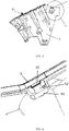
FIG. 1 is a schematic diagram of a rear bumper skin and a rear lamp bracket according to embodiments of the present application. -
FIG. 2 is a schematic diagram of a rear bumper mounting system and a vehicle rear lamp according to embodiments of the present application. -
FIG. 3 is a schematic diagram of a rear bumper side bracket according to embodiments of the present application. -
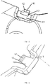
FIG. 4 is a schematic diagram of a third clip part and a fourth clip part according to embodiments of the present application. -
FIG. 5 is a schematic diagram of a third clip part according to embodiments of the present application. -
FIG. 6 is a schematic diagram of a fourth clip part according to embodiments of the present application. -
FIG. 7 is a schematic cross section of a third clip part and a fourth clip part vertical to a contacting surface of the third clip part and the fourth clip part according to embodiments of the present application. - Reference numerals: 1-rear bumper skin; 2-vehicle rear lamp; 3-cutting line; 4-first portion; 5-second portion; 6-third portion; 7-rear lamp bracket; 8-first clip part; 9-rear bumper side bracket; 10-first bracket part; 11-second bracket part; 12-third clip part; 13-third protruding part; 14-third hook part; 15-fourth clip part; 16-fourth protruding part; 17-fourth hook part.
- In order to make the objectives, solutions and advantages according to the embodiments of the present application more clear, the solutions according to the embodiments of the present application will be described clearly and completely below in conjunction with the accompanying drawings in the embodiments of the present application, and it should be noted that the embodiments described are some of the embodiments of the present application rather than all of them. Based on the embodiments of the present application, all other embodiments obtained by those of ordinary skill in the art without creative effort fall within the scope of protection of the present application.
- In the description of the present application, it is to be noted that, the orientation or positional relations specified by terms such as "central", "longitudinal", "transverse", "upper", "lower", "front", "back", "left", "right", "vertical", "horizontal", "top", "bottom", "inner", "outer" and the like, are based on the orientation or positional relations shown in the drawings, which is merely for convenience of description of the present application and to simplify description, but does not indicate or imply that the stated devices or components must have the particular orientation and be constructed and operated in the particular orientation, and thus it is not to be construed as limiting the present application. Furthermore, the terms "first", "second", "third" and the like are only used for descriptive purposes and should not be construed as indicating or implying a relative importance.
- The present application provides a rear bumper mounting system, including: a rear bumper; a rear bumper skin having a first portion, a second portion and a third portion along a cutting line between the rear bumper skin and a vehicle rear lamp, where the first portion extends along Y direction, the third portion extends along X direction, and the second portion connects the first portion and the third portion; a rear lamp bracket, mounted at a rear of the vehicle and connected to the rear bumper by connecting to the rear bumper skin, and the rear lamp bracket is assembled with the first portion relative to the X direction; and a rear bumper side bracket, arranged at a side of the rear of the vehicle to support the rear bumper, and assembled with the third portion relative to the Y direction while ensuring positioning of the second portion relative to the rear lamp.
- In an embodiment, as shown in
FIG. 1 , acutting line 3 between arear bumper skin 1 and a vehicle rear lamp 2 (not shown inFIG. 1 ) is a broken line. Therear bumper skin 1 can be divided into three portions including afirst portion 4, asecond portion 5 and athird portion 6 along thecutting line 3, where thefirst portion 4 extends along Y direction, thethird portion 6 extends along X direction, and thesecond portion 5 is a transition area between thefirst portion 4 and thethird portion 6. - As shown in
FIG. 1 and FIG. 2 , the vehiclerear lamp 2 is connected above arear lamp bracket 7. Therear lamp bracket 7 and the vehiclerear lamp 2 are initially mounted at the rear of the vehicle, and then the assemble of therear bumper skin 1 in X direction is realized by assembling therear lamp bracket 7 with thefirst portion 4 relative to the X direction. Since therear bumper skin 1 and the rear bumper have already been assembled together and both of them are part of the rear bumper assembly, that a portion of the rear bumper assembly is assembled in X direction at the rear of the vehicle is realized finally. X direction is the main mounting direction of the rear bumper assembly. Thefirst portion 4 of therear bumper skin 1 is provided with a first clip hole to connect to therear lamp bracket 7 in a clipping connection manner. Therear lamp bracket 7 is provided with a first clip part 8 corresponding to the first clip hole, and thefirst portion 4 is fixed by the connection of the first clip part 8 and the first clip hole. In an embodiment, therear lamp bracket 7 and thefirst portion 4 is connected in a traditional manner. For example, a flange of thefirst portion 4 of therear bumper skin 1 is provided with three first clip holes, and a corresponding position at therear lamp bracket 7 is provided with three first clip parts 8. During assembly, the first clip part 8 on therear lamp bracket 7 is stuck in the first clip hole. As shown inFIG. 1 , therear lamp bracket 7 controls a position of therear bumper skin 1 here through three first clip parts 8, and then controls a gap flush between therear bumper skin 1 and the vehiclerear lamp 2. - As shown in
FIG. 2 andFIG. 3 , a rearbumper side bracket 9 includes afirst bracket part 10 and asecond bracket part 11 extending from thefirst bracket part 10 to thesecond portion 5, where thefirst bracket part 10 is connected to thethird portion 6 and thesecond bracket part 11 is connected to thesecond portion 5. When thecutting line 3 between therear bumper skin 1 and the vehiclerear lamp 2 is smooth and similar to a straight line, thesecond portion 5 as the transition area does not appear in generally, and there are only thefirst portion 4 and thethird portion 6. At this time, only thefirst bracket part 10 of the rearbumper side bracket 9 and therear lamp bracket 7 are enough to control the gap flush between therear bumper skin 1 and the vehiclerear lamp 2. Since thesecond portion 5 is appeared, and therear lamp bracket 7 cannot extend along the vehiclerear lamp 2, which means that there is no bracket behind thesecond portion 5. At this area, the position of therear bumper skin 1 cannot be controlled. Even if a bracket is provided on a back of therear bumper skin 1 at this area, it will require more force and it will be hard to assemble if a traditional clipping connection is used. In an embodiment, thesecond bracket part 11 is formed by the rearbumper side bracket 9 extending along the direction of thesecond portion 5. Thefirst bracket part 10 and thethird portion 6 are connected by the traditional clipping connection as same as the connection between therear lamp bracket 7 and thefirst portion 4. In an embodiment, thefirst bracket part 10 is provided with 4 second clip parts and thethird portion 6 is provided with 4 second clip holes, and thefirst bracket part 10 and thethird portion 6 are connected by the traditional clipping connection through the 4 second clip parts and 4 second clip holes, and then that the rear bumper assembly is assembled at the rear of the vehicle in Y direction is realized finally. - In an embodiment, the
second bracket part 11 and thesecond portion 5 are also connected in the clipping connection manner, however, the connection structure of which differs from that of the first clip part 8 and the second clip part described above. As shown inFIG. 4 , thesecond bracket part 11 is provided with athird clip part 12 near a corner of thecutting line 3. As shown inFIG. 5 , thethird clip part 12 includes: a thirdprotruding part 13 extending vertically from a surface of thesecond bracket part 11; and athird hook part 14 extending vertically to the third protruding part from one end of the third protrudingpart 13 and forming an upwardly extending hook at a tail end. Accordingly, thesecond portion 5 of therear bumper skin 1 is provided with afourth clip part 15 corresponding to thethird clip part 12, as shown inFIG. 6 . Thefourth clip part 15 includes: a fourth protrudingpart 16 extending vertically from a surface of therear bumper skin 1; and afourth hook part 17 extending vertically to the fourth protrudingpart 16 from one end of the fourth protrudingpart 16 and forming a downwardly extending hook at a tail end. A hook of thethird clip part 12 is hooked together with a hook of thefourth clip part 15 to form a clipping connection. As shown inFIG. 7 , in a cross section vertical to a contacting surface of thethird clip part 12 and thefourth clip part 15, the shape of the connection between thethird clip part 12 and thefourth clip part 15 is similar to two upside down letters "L". - On the other hand, the present application also provides a vehicle including a rear bumper mounting system according to embodiments of the application.
- In summary, the present application provides a rear bumper mounting system, including: a rear bumper; a rear bumper skin having a first portion, a second portion and a third portion along a cutting line between the rear bumper skin and a vehicle rear lamp, where the first portion extends along Y direction, the third portion extends along X direction, and the second portion connects the first portion and the third portion; a rear lamp bracket, mounted at a rear of the vehicle and connected to the rear bumper by connecting to the rear bumper skin, where the rear lamp bracket is assembled with the first portion relative to the X direction; and a rear bumper side bracket, arranged at a side of the rear of the vehicle to support the rear bumper, and assembled with the third portion relative to the Y direction while ensuring positioning of the second portion relative to the rear lamp. The rear bumper mounting system provided by the present application has a simple structure, requires no additional cost, and is easy to assemble.
- Finally, it should be noted that the above embodiments are only used to illustrate the solutions of the present application, but not to limit them; although the present application has been described in detail with reference to the foregoing embodiments, those of ordinary skill in the art should understand that the solutions recorded by the foregoing embodiments can be modified, or some of the features therein can be equivalently replaced; and these modifications or replacements do not make the essence of the corresponding solutions depart from the scope of the solutions of various embodiments of the present application.
Claims (9)
- A rear bumper mounting system, comprising:a rear bumper;a rear bumper skin having a first portion, a second portion and a third portion along a cutting line between the rear bumper skin and a vehicle rear lamp, wherein the first portion extends along Y direction, the third portion extends along X direction, and the second portion connects the first portion and the third portion;a rear lamp bracket, mounted at a rear of the vehicle and connected to the rear bumper by connecting to the rear bumper skin, and the rear lamp bracket is assembled with the first portion relative to the X direction; anda rear bumper side bracket, arranged at a side of the rear of the vehicle to support the rear bumper, and assembled with the third portion relative to the Y direction while ensuring positioning of the second portion relative to the rear lamp.
- The rear bumper mounting system according to claim 1, wherein,
the rear bumper side bracket comprises a first bracket part and a second bracket part extending from the first bracket part to the second portion, wherein the first bracket part is connected to the third portion and the second bracket part is connected to the second portion. - The rear bumper mounting system according to claim 2, wherein,
the second bracket part is provided with a third clip part near a corner of the cutting line, and the third clip part comprises:a third protruding part extending vertically from a surface of the second bracket part; anda third hook part extending vertically to the third protruding part from one end of the third protruding part and forming an upwardly extending hook at a tail end. - The rear bumper mounting system according to claim 1, wherein,
the second portion is provided with a fourth clip part corresponding to the third clip part, and the fourth clip part comprises:a fourth protruding part extending vertically from a surface of the rear bumper skin; anda fourth hook part extending vertically to the fourth protruding part from one end of the fourth protruding part and forming a downwardly extending hook at a tail end. - The rear bumper mounting system according to claim 1, wherein,
the first portion of the rear bumper skin is provided with a first clip hole to connect to the rear lamp bracket in a clipping connection manner. - The rear bumper mounting system according to claim 5, wherein,
the rear lamp bracket is provided with a first clip part corresponding to the first clip hole, and the first portion is fixed by the connection of the first clip part and the first clip hole. - The rear bumper mounting system according to claim 1, wherein,
the third portion of the rear bumper skin is provided with a second clip hole to connect to the first bracket part in a clipping connection manner. - The rear bumper mounting system according to claim 7, wherein,
the first bracket part is provided with a second clip part corresponding to the second clip hole, and the third portion is fixed by the connection of the second clip part and the second clip hole. - A vehicle, comprising the rear bumper mounting system according to any one of claims 1-8.
Applications Claiming Priority (2)
| Application Number | Priority Date | Filing Date | Title |
|---|---|---|---|
| CN202010168024.3A CN113386695A (en) | 2020-03-11 | 2020-03-11 | Rear bumper installing system and vehicle |
| PCT/CN2021/078593 WO2021179946A1 (en) | 2020-03-11 | 2021-03-02 | Rear bumper mounting system and vehicle |
Publications (2)
| Publication Number | Publication Date |
|---|---|
| EP4119401A1 true EP4119401A1 (en) | 2023-01-18 |
| EP4119401A4 EP4119401A4 (en) | 2024-04-10 |
Family
ID=77616645
Family Applications (1)
| Application Number | Title | Priority Date | Filing Date |
|---|---|---|---|
| EP21768275.6A Withdrawn EP4119401A4 (en) | 2020-03-11 | 2021-03-02 | Rear bumper mounting system and vehicle |
Country Status (3)
| Country | Link |
|---|---|
| EP (1) | EP4119401A4 (en) |
| CN (1) | CN113386695A (en) |
| WO (1) | WO2021179946A1 (en) |
Cited By (2)
| Publication number | Priority date | Publication date | Assignee | Title |
|---|---|---|---|---|
| FR3145521A1 (en) | 2023-02-08 | 2024-08-09 | Psa Automobiles Sa | Support under rear light of motor vehicle |
| EP4461604A1 (en) * | 2023-05-12 | 2024-11-13 | Stellantis Auto SAS | Bumper assembly and vehicle |
Families Citing this family (1)
| Publication number | Priority date | Publication date | Assignee | Title |
|---|---|---|---|---|
| FR3134771B1 (en) | 2022-04-25 | 2024-10-25 | Psa Automobiles Sa | Bumper side bracket for automotive vehicle |
Family Cites Families (10)
| Publication number | Priority date | Publication date | Assignee | Title |
|---|---|---|---|---|
| JP2005138663A (en) * | 2003-11-05 | 2005-06-02 | Fuji Heavy Ind Ltd | Vehicle front structure |
| DE102006015399B4 (en) * | 2006-04-03 | 2013-07-18 | Audi Ag | Holding part on a body of a motor vehicle |
| DE102007029002A1 (en) * | 2007-06-23 | 2008-12-24 | Daimler Ag | Carrier arrangement for vehicle, has bumper cladding arranged on bumper base carrier and comprising flap, which is inserted into guide of bumper base carrier at assembled state of bumper base carrier |
| DE102008038842A1 (en) * | 2008-08-13 | 2009-04-02 | Daimler Ag | Bumper arrangement for motor vehicle, particularly for passenger car, has bumper lining adjacent to light unit, where bumper lining is fixed directly by back-gripped connection or locking connection at base carrier of light unit |
| US8183460B2 (en) * | 2009-08-10 | 2012-05-22 | James Williams | Foldable raceway assembly |
| FR2951675A1 (en) * | 2009-10-28 | 2011-04-29 | Peugeot Citroen Automobiles Sa | Rear part for motor vehicle, has intermediate support extended between under-light support and lateral support to support upper edge of each of lateral parts of bumper, where upper edge is fixed to under-light support and lateral support |
| CN201932103U (en) * | 2010-12-31 | 2011-08-17 | 东风汽车股份有限公司 | Automobile bumper |
| DE102013003100B4 (en) * | 2013-02-25 | 2023-08-24 | Dr. Ing. H.C. F. Porsche Aktiengesellschaft | Method of assembling a rear bumper fascia to a motor vehicle and related motor vehicle |
| CN106515634B (en) * | 2015-09-14 | 2019-02-15 | 本田技研工业(中国)投资有限公司 | Rear bumper for automobile panel fixing structural |
| CN204915569U (en) * | 2015-09-17 | 2015-12-30 | 延锋彼欧宁波汽车外饰系统有限公司 | Bumper assembly |
-
2020
- 2020-03-11 CN CN202010168024.3A patent/CN113386695A/en active Pending
-
2021
- 2021-03-02 EP EP21768275.6A patent/EP4119401A4/en not_active Withdrawn
- 2021-03-02 WO PCT/CN2021/078593 patent/WO2021179946A1/en not_active Ceased
Cited By (2)
| Publication number | Priority date | Publication date | Assignee | Title |
|---|---|---|---|---|
| FR3145521A1 (en) | 2023-02-08 | 2024-08-09 | Psa Automobiles Sa | Support under rear light of motor vehicle |
| EP4461604A1 (en) * | 2023-05-12 | 2024-11-13 | Stellantis Auto SAS | Bumper assembly and vehicle |
Also Published As
| Publication number | Publication date |
|---|---|
| WO2021179946A1 (en) | 2021-09-16 |
| CN113386695A (en) | 2021-09-14 |
| EP4119401A4 (en) | 2024-04-10 |
Similar Documents
| Publication | Publication Date | Title |
|---|---|---|
| CN205064470U (en) | Clamping structure | |
| CN217455810U (en) | Mounting structure of car headlamp and grid | |
| CN220615751U (en) | Connection structure of front combination lamp and front bumper | |
| WO2021179946A1 (en) | Rear bumper mounting system and vehicle | |
| EP4049896A1 (en) | Vehicle light assembly, installation method thereof and vehicle | |
| CN110949240B (en) | Resin Back Door Tail Light Mounting Kit and Resin Back Door | |
| CN112407054B (en) | Vehicle side wall structure and vehicle | |
| CN204821101U (en) | Car battery mounting structure | |
| CN222363931U (en) | An integrated stove | |
| CN218907403U (en) | Instrument panel mounting structure and vehicle | |
| CN208138389U (en) | A kind of drag chain | |
| CN219584071U (en) | Accuse case installing support and car in car | |
| CN220577136U (en) | Car light fixing device and loader | |
| CN207045698U (en) | A kind of elevator suspended bearer | |
| CN221678672U (en) | Bumper Mount Trailer Bracket and Vehicle | |
| CN220262652U (en) | Automobile combined lamp socket board connecting plate | |
| CN219756204U (en) | Laser projection fluorescent sheet connection structure | |
| CN220349597U (en) | CCB left-right rudder shared support structure | |
| CN218781169U (en) | Back bend and street lamp | |
| CN219214879U (en) | Vehicle radar support and vehicle | |
| US12606249B2 (en) | Vehicle body front structure | |
| CN214124435U (en) | Simple power distribution cabinet supporting and matching assembly | |
| CN218367690U (en) | Vehicle bumper mounting bracket | |
| CN214984795U (en) | Novel multifunctional support structure | |
| CN222061866U (en) | Daytime lamp mounting structure and vehicle |
Legal Events
| Date | Code | Title | Description |
|---|---|---|---|
| STAA | Information on the status of an ep patent application or granted ep patent |
Free format text: STATUS: THE INTERNATIONAL PUBLICATION HAS BEEN MADE |
|
| PUAI | Public reference made under article 153(3) epc to a published international application that has entered the european phase |
Free format text: ORIGINAL CODE: 0009012 |
|
| STAA | Information on the status of an ep patent application or granted ep patent |
Free format text: STATUS: REQUEST FOR EXAMINATION WAS MADE |
|
| 17P | Request for examination filed |
Effective date: 20220929 |
|
| AK | Designated contracting states |
Kind code of ref document: A1 Designated state(s): AL AT BE BG CH CY CZ DE DK EE ES FI FR GB GR HR HU IE IS IT LI LT LU LV MC MK MT NL NO PL PT RO RS SE SI SK SM TR |
|
| DAV | Request for validation of the european patent (deleted) | ||
| DAX | Request for extension of the european patent (deleted) | ||
| RAP3 | Party data changed (applicant data changed or rights of an application transferred) |
Owner name: STELLANTIS AUTO SAS |
|
| A4 | Supplementary search report drawn up and despatched |
Effective date: 20240313 |
|
| RIC1 | Information provided on ipc code assigned before grant |
Ipc: B60Q 1/26 20060101ALI20240306BHEP Ipc: B60R 19/24 20060101AFI20240306BHEP |
|
| STAA | Information on the status of an ep patent application or granted ep patent |
Free format text: STATUS: THE APPLICATION IS DEEMED TO BE WITHDRAWN |
|
| 18D | Application deemed to be withdrawn |
Effective date: 20241005 |