EP4119397B1 - Improved tube-holding device for vehicles - Google Patents
Improved tube-holding device for vehicles Download PDFInfo
- Publication number
- EP4119397B1 EP4119397B1 EP22180150.9A EP22180150A EP4119397B1 EP 4119397 B1 EP4119397 B1 EP 4119397B1 EP 22180150 A EP22180150 A EP 22180150A EP 4119397 B1 EP4119397 B1 EP 4119397B1
- Authority
- EP
- European Patent Office
- Prior art keywords
- tube
- holding device
- closing cover
- closing
- access threshold
- Prior art date
- Legal status (The legal status is an assumption and is not a legal conclusion. Google has not performed a legal analysis and makes no representation as to the accuracy of the status listed.)
- Active
Links
Images

Classifications
-
- B—PERFORMING OPERATIONS; TRANSPORTING
- B60—VEHICLES IN GENERAL
- B60R—VEHICLES, VEHICLE FITTINGS, OR VEHICLE PARTS, NOT OTHERWISE PROVIDED FOR
- B60R9/00—Supplementary fittings on vehicle exterior for carrying loads, e.g. luggage, sports gear or the like
- B60R9/04—Carriers associated with vehicle roof
- B60R9/055—Enclosure-type carriers, e.g. containers, boxes
-
- F—MECHANICAL ENGINEERING; LIGHTING; HEATING; WEAPONS; BLASTING
- F16—ENGINEERING ELEMENTS AND UNITS; GENERAL MEASURES FOR PRODUCING AND MAINTAINING EFFECTIVE FUNCTIONING OF MACHINES OR INSTALLATIONS; THERMAL INSULATION IN GENERAL
- F16B—DEVICES FOR FASTENING OR SECURING CONSTRUCTIONAL ELEMENTS OR MACHINE PARTS TOGETHER, e.g. NAILS, BOLTS, CIRCLIPS, CLAMPS, CLIPS OR WEDGES; JOINTS OR JOINTING
- F16B5/00—Joining sheets or plates, e.g. panels, to one another or to strips or bars parallel to them
- F16B5/06—Joining sheets or plates, e.g. panels, to one another or to strips or bars parallel to them by means of clamps or clips
- F16B5/0607—Joining sheets or plates, e.g. panels, to one another or to strips or bars parallel to them by means of clamps or clips joining sheets or plates to each other
- F16B5/0614—Joining sheets or plates, e.g. panels, to one another or to strips or bars parallel to them by means of clamps or clips joining sheets or plates to each other in angled relationship
-
- F—MECHANICAL ENGINEERING; LIGHTING; HEATING; WEAPONS; BLASTING
- F16—ENGINEERING ELEMENTS AND UNITS; GENERAL MEASURES FOR PRODUCING AND MAINTAINING EFFECTIVE FUNCTIONING OF MACHINES OR INSTALLATIONS; THERMAL INSULATION IN GENERAL
- F16B—DEVICES FOR FASTENING OR SECURING CONSTRUCTIONAL ELEMENTS OR MACHINE PARTS TOGETHER, e.g. NAILS, BOLTS, CIRCLIPS, CLAMPS, CLIPS OR WEDGES; JOINTS OR JOINTING
- F16B7/00—Connections of rods or tubes, e.g. of non-circular section, mutually, including resilient connections
- F16B7/18—Connections of rods or tubes, e.g. of non-circular section, mutually, including resilient connections using screw-thread elements
- F16B7/182—Connections of rods or tubes, e.g. of non-circular section, mutually, including resilient connections using screw-thread elements for coaxial connections of two rods or tubes
Definitions
- the present invention relates to an improved tube-holding device for vehicles.
- tube-holding devices normally arranged on the roof of the vehicle are used, either directly or through the interposition of luggage rack bars that are in turn attached to the roof of the vehicle.
- Said tube-holding devices must have precise technical features in order to withstand the severe conditions to which they are subjected.
- these tube-holding devices must be able to provide easy accessibility to their containment compartment in order to allow the objects stored therein to be taken out. Moreover, once access to the containment compartment has been opened by rotating the appropriate closing cover, it is necessary to prevent said closing cover from accidentally closing again, e.g., due to its own weight, by the wind, or even because the vehicle is in a sloping condition, i.e., on a road that is not perfectly flat.
- a tube-holding device for a vehicle comprising a hollow device body 8, enclosing a containment compartment 12 for containing objects.
- the tube-holding device 4 preferably contains elongated objects, such as tubes, but other objects as well.
- the type of objects contained in the containment compartment 12 is only indicative and non-restrictive.
- the device body 8 may be made of either metal or a plastic/polymer material.
- the device body 8 extends along a prevailing longitudinal direction X-X from a front end 16 to a rear end 20.
- the device body 8 further comprises a closing cover 24, joined to the front end 16, which may be opened to allow access to the containment compartment 12, through a relative access threshold 28.
- the device body 8 further comprises a rear closing cap 32 joined to the rear end 20.
- the closing cover 24 is hinged at an upper wall 36 of the device body 8, opposite a roof or associated vehicle rack, by at least one upper hinge 40 with a horizontal axis Y-Y, perpendicular to said prevailing longitudinal direction X-X and parallel to said upper wall 36.
- the access threshold 28 is at least partially inclined with respect to a vertical plane P, perpendicular to said prevailing longitudinal direction X-X, and passing through said horizontal axis Y-Y of the upper hinge 40.
- the closing cover 24 comprises a closing edge 44, counter-shaped to said access threshold 28. Due to this shape, the closure of the containment compartment 12 is achieved when the closing cover 24 is returned to the closing configuration by bringing the closing edge 44 of the closing cover 24 into contact with the access threshold 28 of the front end 16 of the device body 8.
- the access threshold 28 lies at least partially on an inclined plane Z that identifies an angle B between 10° and 60° with said vertical plane P, wherein the inclined plane Z and the vertical plane P intersect at the upper hinge 40.
- the access threshold 28 comprises at least a concave or convex portion on the side of the associated closing cover 24.
- an inner stop wall 48 of the closing cover 24, facing said access threshold 28 and said containment compartment 12, is at least partially counter-shaped to said access threshold 28.
- a sealing means such as a rubber gasket, is interposed between the access threshold 28 and the closing cover 24.
- a male-female type coupling is made at respective perimeter edges.
- the closing cover 24, at a connection portion 52 to the upper hinge 40 comprises a ferromagnetic plate or portion 52 so that it may magnetically engage with a corresponding metal or ferromagnetic plate 56 arranged on the upper wall 36 of the device body 8 when tilted around the upper hinge 40 in the maximum opening position of the closing cover 24.
- the upper hinge 40 is preferably fitted with hermetically sealed side closing caps 64.
- the device body 8 is fitted with at least one partition 68 that internally divides the containment compartment 12 into at least two distinct volumes.
- said at least one longitudinal partition 68 is removable and is attached internally to the device body 8 by means of a track-like coupling.
- the device body 8 is fitted with a bottom partition 72, arranged on the opposite side of the top hinge 40, which divides the containment compartment 12 from a locking compartment 76 of the closing cover 24 which houses locking means 80 of the closing cover 24.
- the rear closing cap 32 is joined with the rear end 20 by the insertion of a sealing means, such as, for example, a gasket.
- the rear closing cap 32 joined with the rear end 20, may be either fixed or openable or removable.
- the rear closing cap 32 is configured as the closing cover 24; in other words, it is possible to make a tube-holding device 4 that has similar or identical closing covers 24 at its respective front 16 and rear 20 ends, as described above.
- the present invention overcomes the drawbacks of the prior art.
- the present invention allows the device to withstand weather conditions, ensuring that it remains sealed over time, particularly by preventing possible water infiltration therein.
- the tube-holding device is solid, fitted with suitable gaskets, and does not involve through-wall rivets, as in many solutions of the prior art, said through-wall rivets being in fact in the long run the cause of water infiltration.
- the objects contained in the containment compartment transfer the impulsive force gradually to the closing cover at distinct instants of time and to different portions of the closing cover. In this way, the impact resistance of the closing cover is improved with respect to the solutions of the prior art.
- the special geometric shape of the closing cover ensures easy accessibility to the containment compartment in order to allow the objects stored therein to be taken out.
- the closing cover does not tend to close accidentally, due to weight or wind, even if the vehicle is on sloping ground.
- the closing cover in the fully open condition rotates 180 degrees so that it rests on the upper wall of the device body in a stable and secure position.
Landscapes
- Engineering & Computer Science (AREA)
- General Engineering & Computer Science (AREA)
- Mechanical Engineering (AREA)
- Supports For Pipes And Cables (AREA)
- Cooling, Air Intake And Gas Exhaust, And Fuel Tank Arrangements In Propulsion Units (AREA)
- Fittings On The Vehicle Exterior For Carrying Loads, And Devices For Holding Or Mounting Articles (AREA)
Description
- The present invention relates to an improved tube-holding device for vehicles.
- As is known, in the field of vehicles, industrial and otherwise, tube-holding devices normally arranged on the roof of the vehicle are used, either directly or through the interposition of luggage rack bars that are in turn attached to the roof of the vehicle.
- Said tube-holding devices must have precise technical features in order to withstand the severe conditions to which they are subjected.
- First of all, these are containers placed in the open air, on the roof of the vehicle, and therefore they must withstand the weather, ensuring that they remain sealed over time, particularly by preventing possible water infiltration inside of them.
- In addition, they must provide considerable mechanical resistance to impact, especially preventing the dispersion of the objects contained therein in the event of severe deceleration of the vehicle to which they are applied (e.g., in the event of collisions or accidents that may involve said vehicle).
- Further, these tube-holding devices must be able to provide easy accessibility to their containment compartment in order to allow the objects stored therein to be taken out. Moreover, once access to the containment compartment has been opened by rotating the appropriate closing cover, it is necessary to prevent said closing cover from accidentally closing again, e.g., due to its own weight, by the wind, or even because the vehicle is in a sloping condition, i.e., on a road that is not perfectly flat.
- The solutions of the prior art are not able to solve the aforementioned technical problems. Such solutions are disclosed, for example, by
GB 2272426 A US 5464141 A andDE2428438 A1 . - Thus, there is a need to resolve the cited drawbacks and limitations in reference to the prior art.
- This need is satisfied by a tube-holding device according to claim 1.
- Further features and advantages of the present invention will be more readily understood from the following description of its preferred and non-limiting examples of embodiments, wherein:
-
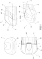
Fig. 1 shows a plurality of views of a front or anterior portion of a tube-holding device according to an embodiment of the present invention with the closing cover in a closed configuration; -
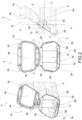
Fig. 2 shows a plurality of views of the front portion of the tube-holding device inFig. 1 with the closing cover in the open configuration; -
Fig. 3-4 show enlarged details ofFig. 1 and2 ; -
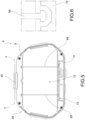
Fig. 5 shows a front view of the device inFig. 1 with the closing cover in the open configuration; -
Fig. 6 shows the enlarged detail VI indicated inFig. 5 ; -
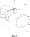
Fig. 7 shows a perspective view of the tube-holding device inFig. 1 , from the side of a rear portion, in an exploded configuration. - The elements or parts of elements common to the embodiments described hereinafter will be indicated with the same reference numerals.
- With reference to the aforesaid
figures, 4 has been used to collectively denote a tube-holding device for a vehicle comprising ahollow device body 8, enclosing acontainment compartment 12 for containing objects. - In particular, the tube-
holding device 4 preferably contains elongated objects, such as tubes, but other objects as well. In any case, the type of objects contained in thecontainment compartment 12 is only indicative and non-restrictive. - The
device body 8 may be made of either metal or a plastic/polymer material. - Preferably, the
device body 8 extends along a prevailing longitudinal direction X-X from afront end 16 to arear end 20. - The
device body 8 further comprises aclosing cover 24, joined to thefront end 16, which may be opened to allow access to thecontainment compartment 12, through arelative access threshold 28. - The
device body 8 further comprises arear closing cap 32 joined to therear end 20. - The
closing cover 24 is hinged at anupper wall 36 of thedevice body 8, opposite a roof or associated vehicle rack, by at least oneupper hinge 40 with a horizontal axis Y-Y, perpendicular to said prevailing longitudinal direction X-X and parallel to saidupper wall 36. - The
access threshold 28 is at least partially inclined with respect to a vertical plane P, perpendicular to said prevailing longitudinal direction X-X, and passing through said horizontal axis Y-Y of theupper hinge 40. - Preferably, the
closing cover 24 comprises aclosing edge 44, counter-shaped to saidaccess threshold 28. Due to this shape, the closure of thecontainment compartment 12 is achieved when theclosing cover 24 is returned to the closing configuration by bringing theclosing edge 44 of theclosing cover 24 into contact with theaccess threshold 28 of thefront end 16 of thedevice body 8. - According to a possible embodiment, the
access threshold 28 lies at least partially on an inclined plane Z that identifies an angle B between 10° and 60° with said vertical plane P, wherein the inclined plane Z and the vertical plane P intersect at theupper hinge 40. - According to a possible embodiment, the
access threshold 28 comprises at least a concave or convex portion on the side of the associatedclosing cover 24. - Preferably, an
inner stop wall 48 of theclosing cover 24, facing saidaccess threshold 28 and saidcontainment compartment 12, is at least partially counter-shaped to saidaccess threshold 28. - Preferably, a sealing means, such as a rubber gasket, is interposed between the
access threshold 28 and theclosing cover 24. - It is also possible to envisage that, between the
access threshold 28 and theclosing cover 24, a male-female type coupling is made at respective perimeter edges. - According to a possible embodiment, the
closing cover 24, at a connection portion 52 to theupper hinge 40, comprises a ferromagnetic plate or portion 52 so that it may magnetically engage with a corresponding metal or ferromagnetic plate 56 arranged on theupper wall 36 of thedevice body 8 when tilted around theupper hinge 40 in the maximum opening position of theclosing cover 24. It is clear that if the device body itself is made of a ferromagnetic material, there is no need to add a specific metal plate on said device body. Obviously, the opposing positioning between the magnet and the metal plate, i.e., the arrangement of two magnets attracting each other, also applies. - The
upper hinge 40 is preferably fitted with hermetically sealedside closing caps 64. - According to a possible embodiment, the
device body 8 is fitted with at least onepartition 68 that internally divides thecontainment compartment 12 into at least two distinct volumes. - Preferably, said at least one
longitudinal partition 68 is removable and is attached internally to thedevice body 8 by means of a track-like coupling. - The
device body 8 is fitted with abottom partition 72, arranged on the opposite side of thetop hinge 40, which divides thecontainment compartment 12 from alocking compartment 76 of theclosing cover 24 which houses locking means 80 of theclosing cover 24. - Preferably, but not necessarily, the
rear closing cap 32 is joined with therear end 20 by the insertion of a sealing means, such as, for example, a gasket. - The
rear closing cap 32, joined with therear end 20, may be either fixed or openable or removable. - According to a possible variant embodiment, the
rear closing cap 32 is configured as theclosing cover 24; in other words, it is possible to make a tube-holding device 4 that has similar oridentical closing covers 24 at itsrespective front 16 and rear 20 ends, as described above. - As may be appreciated from that which has been described, the present invention overcomes the drawbacks of the prior art.
- First, the present invention allows the device to withstand weather conditions, ensuring that it remains sealed over time, particularly by preventing possible water infiltration therein.
- In fact, the tube-holding device is solid, fitted with suitable gaskets, and does not involve through-wall rivets, as in many solutions of the prior art, said through-wall rivets being in fact in the long run the cause of water infiltration.
- Moreover, due to the tapering or flaring pattern of the coupling portion between the device body and the closing cover, in the event of shocks or strong deceleration, the objects contained in the containment compartment transfer the impulsive force gradually to the closing cover at distinct instants of time and to different portions of the closing cover. In this way, the impact resistance of the closing cover is improved with respect to the solutions of the prior art.
- Therefore, the risk of breakage of the closing cover and related dispersion of the load contained in the tube-holding device is averted.
- In addition, the special geometric shape of the closing cover ensures easy accessibility to the containment compartment in order to allow the objects stored therein to be taken out.
- Further, once access to the containment compartment has been opened by rotating the closing cover, the closing cover does not tend to close accidentally, due to weight or wind, even if the vehicle is on sloping ground.
- In fact, as shown, the closing cover in the fully open condition rotates 180 degrees so that it rests on the upper wall of the device body in a stable and secure position.
- Moreover, the use of magnetic stopping means prevents any accidental and unwanted closing of the closing cover.
- A person skilled in the art, in order to satisfy contingent and specific needs, may make numerous modifications and variations to the solutions described above.
- The scope of protection of the present invention is defined by the following claims.
Claims (13)
- Tube-holding device (4) for vehicles comprising- a hollow device body (8), enclosing a containment compartment (12) for objects, said device body (8) extending in a prevailing longitudinal direction (X-X) from a front end (16) to a rear end (20),- a closing cover (24), joined to the front end (16), which may be opened so as to allow access to the containment compartment (12), through a relative access threshold (28),- a rear closure cap (32) joined to the rear end (20),- wherein the closing cover (24) is hinged at an upper wall (36) of the device body (8), opposite a roof or an associated vehicle luggage rack, by means of at least one upper hinge (40) having a horizontal axis (Y-Y), perpendicular to said prevailing longitudinal direction (X-X) and parallel to said upper wall (36),- wherein the access threshold (28) is at least partially inclined with respect to a vertical plane (P), perpendicular to said prevailing longitudinal direction (X-X), and passing through said horizontal axis (Y-Y) of the upper hinge (40),- wherein the closing cover (24) comprises a closing edge (44) counter-shaped with respect to said access threshold (28),characterized in that the device body (8) is provided with a bottom partition (72), placed opposite the upper hinge (40) which divides the containment compartment (12) from a locking compartment (76) of the closing cover (24) housing locking means (80) of the closing cover (24).
- The tube-holding device (4) according to claim 1, wherein the access threshold (28) lies at least partially on an inclined plane (Z) which identifies with said vertical plane (P) an angle (B) between 10° and 60°, said inclined plane (Z) and vertical plane (P) intersecting at the upper hinge 40().
- The tube-holding device (4) according to any of the claims 1 to 2, wherein the access threshold (28) comprises at least one concave or convex portion on the side of the associated closing cover (24).
- The tube-holding device (4) according to any of the claims from 1 to 3, wherein an inner stop wall (48) of the closing cover (24), facing said access threshold (28) and said containment compartment (12), is at least partially counter-shaped with respect to said access threshold (28).
- The tube-holding device (4) according to any of the claims from 1 to 4, wherein a sealing means is interposed between the access threshold (28) and the closing cover (24).
- The tube-holding device (4) according to any of the claims from 1 to 5, wherein a male-female type coupling is made between the access threshold (28) and the closing cover (24) at respective perimeter edges.
- The tube-holding device (4) according to any of the claims from 1 to 6, wherein the closing cover (24), at a connection portion (52) to the upper hinge (40) comprises a ferromagnetic plate or portion (56) so that it may be magnetically coupled to a corresponding metal or ferromagnetic plate (60) placed on the upper wall of the device body (8) when tilted around the upper hinge (40) in the maximum opening position of the closing cover (24) .
- The tube-holding device (4) according to any of the claims from 1 to 7, wherein the upper hinge (40) is provided with hermetically sealed side closing caps (64).
- The tube-holding device (4) according to any of the claims from 1 to 8, wherein the device body (8) is provided with at least one longitudinal partition (68) which internally divides the containment compartment into at least two distinct volumes.
- The tube-holding device (4) according to claim 9, wherein said at least one longitudinal partition (68) is removable and is coupled internally to the device body (8) by means of a rail coupling.
- The tube-holding device (4) according to any of the claims from 1 to 10, wherein the rear closing cap (64) is associated with the rear end (20) by insertion of a sealing means.
- The tube-holding device (4) according to any of the claims from 1 to 11, wherein the rear closing cap (32) joined to the rear end (20), may be opened.
- The tube-holding device (4) according to any of the claims from 1 to 12, wherein the rear closing cap (32) joined to the rear end (20), is configured as the closing cover (24).
Applications Claiming Priority (1)
| Application Number | Priority Date | Filing Date | Title |
|---|---|---|---|
| IT102021000018572A IT202100018572A1 (en) | 2021-07-14 | 2021-07-14 | IMPROVED HOSE HOLDER FOR VEHICLES |
Publications (2)
| Publication Number | Publication Date |
|---|---|
| EP4119397A1 EP4119397A1 (en) | 2023-01-18 |
| EP4119397B1 true EP4119397B1 (en) | 2025-05-28 |
Family
ID=78049666
Family Applications (1)
| Application Number | Title | Priority Date | Filing Date |
|---|---|---|---|
| EP22180150.9A Active EP4119397B1 (en) | 2021-07-14 | 2022-06-21 | Improved tube-holding device for vehicles |
Country Status (2)
| Country | Link |
|---|---|
| EP (1) | EP4119397B1 (en) |
| IT (1) | IT202100018572A1 (en) |
Families Citing this family (2)
| Publication number | Priority date | Publication date | Assignee | Title |
|---|---|---|---|---|
| EP4653258A1 (en) * | 2024-05-22 | 2025-11-26 | Lokhen S.r.l. | Improved tube container for vehicle |
| EP4686613A1 (en) * | 2024-08-01 | 2026-02-04 | Lokhen S.r.l. | Improved tube container for vehicles |
Citations (1)
| Publication number | Priority date | Publication date | Assignee | Title |
|---|---|---|---|---|
| WO2018031335A1 (en) * | 2016-08-08 | 2018-02-15 | Horizon Global Americas Inc. | Segmented tube carrier |
Family Cites Families (8)
| Publication number | Priority date | Publication date | Assignee | Title |
|---|---|---|---|---|
| DE2428438A1 (en) * | 1974-06-12 | 1976-01-02 | Fritz Rick | Roof mounted luggage box for car - with side access doors and streamlined shape having upper ski racks |
| DE3419430A1 (en) * | 1984-05-24 | 1985-11-28 | Anton 8100 Garmisch-Partenkirchen Mangold | Car roof case |
| GB2272426A (en) * | 1992-11-14 | 1994-05-18 | Shop & Interior Contracts Limi | Container for mounting on a vehicle |
| US5464141A (en) * | 1994-03-07 | 1995-11-07 | Brindle; David R. | Rooftop pipe container |
| DE10250019B8 (en) * | 2002-10-25 | 2007-06-21 | Webasto Ag | Vehicle roof with a closable transport container |
| US10286853B1 (en) * | 2018-05-04 | 2019-05-14 | Frank Louis Carbone | Automated self-loading cargo carrier for vehicles |
| DE112019004713T5 (en) * | 2018-09-20 | 2021-06-02 | Lokhen S.R.L. | NOZZLE BRACKET FOR A NOZZLE ON FUEL TRUCK AND RELATED MANUFACTURING PROCESS |
| JP2021102411A (en) * | 2019-12-25 | 2021-07-15 | 株式会社カーメイト | Roof box |
-
2021
- 2021-07-14 IT IT102021000018572A patent/IT202100018572A1/en unknown
-
2022
- 2022-06-21 EP EP22180150.9A patent/EP4119397B1/en active Active
Patent Citations (1)
| Publication number | Priority date | Publication date | Assignee | Title |
|---|---|---|---|---|
| WO2018031335A1 (en) * | 2016-08-08 | 2018-02-15 | Horizon Global Americas Inc. | Segmented tube carrier |
Also Published As
| Publication number | Publication date |
|---|---|
| EP4119397A1 (en) | 2023-01-18 |
| IT202100018572A1 (en) | 2023-01-14 |
Similar Documents
| Publication | Publication Date | Title |
|---|---|---|
| EP4119397B1 (en) | Improved tube-holding device for vehicles | |
| CN101029492B (en) | Closure device | |
| EP1995180B1 (en) | Synthetic resin made tube container | |
| US5380604A (en) | Lead accumulator | |
| AU2018236832B2 (en) | Lightweight Ammunition Box | |
| WO2018056549A1 (en) | Sealed container cover | |
| WO2009059155A1 (en) | Carrying case with pressure relief valve | |
| US5983539A (en) | Tag lock | |
| US5275028A (en) | Padlock protector | |
| KR100983025B1 (en) | Wing body locking device | |
| ES2321258A1 (en) | OPERATOR ACCESS DOOR FOR UNDERGROUND BUILDINGS. | |
| HU217703B (en) | Liquid propane gas tank in particular cylindrical fuel tank for vehicles | |
| KR20150116867A (en) | Container for storing bold ammunition on a ship | |
| CN218246748U (en) | Case is put in theftproof express delivery | |
| EP4257507B1 (en) | Container with lid retainer system | |
| US12441522B2 (en) | Reclosable container comprising an assembly of a bin and a separate cover that is designed to close and lock the bin | |
| FI84801B (en) | SNABBLAOSANORDNING FOER LOCKFOERSEDD BEHAOLLARE. | |
| KR102663938B1 (en) | Apparatus for Installing And Proctecting Electrical Device of Smart Container | |
| WO2007056487A2 (en) | Postal mailbox | |
| WO2009043687A1 (en) | Plastic container | |
| US10150364B2 (en) | Fluid containers to evacuate spilled fluid from the interior of an enclosure of the fluid container | |
| GB2060862A (en) | Vacuum flask | |
| ES2587735B2 (en) | Anti-theft closure device for the side-type paper-cardboard container lids | |
| ES1266322U (en) | Safety lock (Machine-translation by Google Translate, not legally binding) | |
| ES1070041U (en) | Security closure for vehicles (Machine-translation by Google Translate, not legally binding) |
Legal Events
| Date | Code | Title | Description |
|---|---|---|---|
| PUAI | Public reference made under article 153(3) epc to a published international application that has entered the european phase |
Free format text: ORIGINAL CODE: 0009012 |
|
| STAA | Information on the status of an ep patent application or granted ep patent |
Free format text: STATUS: THE APPLICATION HAS BEEN PUBLISHED |
|
| AK | Designated contracting states |
Kind code of ref document: A1 Designated state(s): AL AT BE BG CH CY CZ DE DK EE ES FI FR GB GR HR HU IE IS IT LI LT LU LV MC MK MT NL NO PL PT RO RS SE SI SK SM TR |
|
| STAA | Information on the status of an ep patent application or granted ep patent |
Free format text: STATUS: REQUEST FOR EXAMINATION WAS MADE |
|
| 17P | Request for examination filed |
Effective date: 20230331 |
|
| RBV | Designated contracting states (corrected) |
Designated state(s): AL AT BE BG CH CY CZ DE DK EE ES FI FR GB GR HR HU IE IS IT LI LT LU LV MC MK MT NL NO PL PT RO RS SE SI SK SM TR |
|
| P01 | Opt-out of the competence of the unified patent court (upc) registered |
Effective date: 20230517 |
|
| STAA | Information on the status of an ep patent application or granted ep patent |
Free format text: STATUS: EXAMINATION IS IN PROGRESS |
|
| 17Q | First examination report despatched |
Effective date: 20240508 |
|
| GRAP | Despatch of communication of intention to grant a patent |
Free format text: ORIGINAL CODE: EPIDOSNIGR1 |
|
| STAA | Information on the status of an ep patent application or granted ep patent |
Free format text: STATUS: GRANT OF PATENT IS INTENDED |
|
| INTG | Intention to grant announced |
Effective date: 20250305 |
|
| RIN1 | Information on inventor provided before grant (corrected) |
Inventor name: GRECO, LUCA ORONZO Inventor name: BARATTINI, DANIELE |
|
| GRAS | Grant fee paid |
Free format text: ORIGINAL CODE: EPIDOSNIGR3 |
|
| GRAA | (expected) grant |
Free format text: ORIGINAL CODE: 0009210 |
|
| STAA | Information on the status of an ep patent application or granted ep patent |
Free format text: STATUS: THE PATENT HAS BEEN GRANTED |
|
| AK | Designated contracting states |
Kind code of ref document: B1 Designated state(s): AL AT BE BG CH CY CZ DE DK EE ES FI FR GB GR HR HU IE IS IT LI LT LU LV MC MK MT NL NO PL PT RO RS SE SI SK SM TR |
|
| REG | Reference to a national code |
Ref country code: GB Ref legal event code: FG4D |
|
| REG | Reference to a national code |
Ref country code: CH Ref legal event code: EP |
|
| REG | Reference to a national code |
Ref country code: IE Ref legal event code: FG4D Ref country code: DE Ref legal event code: R096 Ref document number: 602022015133 Country of ref document: DE |
|
| PGFP | Annual fee paid to national office [announced via postgrant information from national office to epo] |
Ref country code: AT Payment date: 20250721 Year of fee payment: 4 |
|
| REG | Reference to a national code |
Ref country code: NL Ref legal event code: MP Effective date: 20250528 |
|
| PG25 | Lapsed in a contracting state [announced via postgrant information from national office to epo] |
Ref country code: ES Free format text: LAPSE BECAUSE OF FAILURE TO SUBMIT A TRANSLATION OF THE DESCRIPTION OR TO PAY THE FEE WITHIN THE PRESCRIBED TIME-LIMIT Effective date: 20250528 Ref country code: FI Free format text: LAPSE BECAUSE OF FAILURE TO SUBMIT A TRANSLATION OF THE DESCRIPTION OR TO PAY THE FEE WITHIN THE PRESCRIBED TIME-LIMIT Effective date: 20250528 |
|
| PGFP | Annual fee paid to national office [announced via postgrant information from national office to epo] |
Ref country code: DE Payment date: 20250717 Year of fee payment: 4 |
|
| REG | Reference to a national code |
Ref country code: LT Ref legal event code: MG9D |
|
| PG25 | Lapsed in a contracting state [announced via postgrant information from national office to epo] |
Ref country code: NO Free format text: LAPSE BECAUSE OF FAILURE TO SUBMIT A TRANSLATION OF THE DESCRIPTION OR TO PAY THE FEE WITHIN THE PRESCRIBED TIME-LIMIT Effective date: 20250828 Ref country code: GR Free format text: LAPSE BECAUSE OF FAILURE TO SUBMIT A TRANSLATION OF THE DESCRIPTION OR TO PAY THE FEE WITHIN THE PRESCRIBED TIME-LIMIT Effective date: 20250829 |
|
| PG25 | Lapsed in a contracting state [announced via postgrant information from national office to epo] |
Ref country code: NL Free format text: LAPSE BECAUSE OF FAILURE TO SUBMIT A TRANSLATION OF THE DESCRIPTION OR TO PAY THE FEE WITHIN THE PRESCRIBED TIME-LIMIT Effective date: 20250528 Ref country code: PL Free format text: LAPSE BECAUSE OF FAILURE TO SUBMIT A TRANSLATION OF THE DESCRIPTION OR TO PAY THE FEE WITHIN THE PRESCRIBED TIME-LIMIT Effective date: 20250528 |
|
| PGFP | Annual fee paid to national office [announced via postgrant information from national office to epo] |
Ref country code: IT Payment date: 20250630 Year of fee payment: 4 |
|
| PG25 | Lapsed in a contracting state [announced via postgrant information from national office to epo] |
Ref country code: BG Free format text: LAPSE BECAUSE OF FAILURE TO SUBMIT A TRANSLATION OF THE DESCRIPTION OR TO PAY THE FEE WITHIN THE PRESCRIBED TIME-LIMIT Effective date: 20250528 |
|
| PG25 | Lapsed in a contracting state [announced via postgrant information from national office to epo] |
Ref country code: HR Free format text: LAPSE BECAUSE OF FAILURE TO SUBMIT A TRANSLATION OF THE DESCRIPTION OR TO PAY THE FEE WITHIN THE PRESCRIBED TIME-LIMIT Effective date: 20250528 |
|
| PG25 | Lapsed in a contracting state [announced via postgrant information from national office to epo] |
Ref country code: RS Free format text: LAPSE BECAUSE OF FAILURE TO SUBMIT A TRANSLATION OF THE DESCRIPTION OR TO PAY THE FEE WITHIN THE PRESCRIBED TIME-LIMIT Effective date: 20250828 |
|
| PG25 | Lapsed in a contracting state [announced via postgrant information from national office to epo] |
Ref country code: IS Free format text: LAPSE BECAUSE OF FAILURE TO SUBMIT A TRANSLATION OF THE DESCRIPTION OR TO PAY THE FEE WITHIN THE PRESCRIBED TIME-LIMIT Effective date: 20250928 |
|
| PG25 | Lapsed in a contracting state [announced via postgrant information from national office to epo] |
Ref country code: LV Free format text: LAPSE BECAUSE OF FAILURE TO SUBMIT A TRANSLATION OF THE DESCRIPTION OR TO PAY THE FEE WITHIN THE PRESCRIBED TIME-LIMIT Effective date: 20250528 |
|
| REG | Reference to a national code |
Ref country code: AT Ref legal event code: MK05 Ref document number: 1798467 Country of ref document: AT Kind code of ref document: T Effective date: 20250528 |
|
| PG25 | Lapsed in a contracting state [announced via postgrant information from national office to epo] |
Ref country code: SM Free format text: LAPSE BECAUSE OF FAILURE TO SUBMIT A TRANSLATION OF THE DESCRIPTION OR TO PAY THE FEE WITHIN THE PRESCRIBED TIME-LIMIT Effective date: 20250528 Ref country code: AT Free format text: LAPSE BECAUSE OF FAILURE TO SUBMIT A TRANSLATION OF THE DESCRIPTION OR TO PAY THE FEE WITHIN THE PRESCRIBED TIME-LIMIT Effective date: 20250528 Ref country code: DK Free format text: LAPSE BECAUSE OF FAILURE TO SUBMIT A TRANSLATION OF THE DESCRIPTION OR TO PAY THE FEE WITHIN THE PRESCRIBED TIME-LIMIT Effective date: 20250528 |
|
| PG25 | Lapsed in a contracting state [announced via postgrant information from national office to epo] |
Ref country code: CZ Free format text: LAPSE BECAUSE OF FAILURE TO SUBMIT A TRANSLATION OF THE DESCRIPTION OR TO PAY THE FEE WITHIN THE PRESCRIBED TIME-LIMIT Effective date: 20250528 |
|
| PG25 | Lapsed in a contracting state [announced via postgrant information from national office to epo] |
Ref country code: EE Free format text: LAPSE BECAUSE OF FAILURE TO SUBMIT A TRANSLATION OF THE DESCRIPTION OR TO PAY THE FEE WITHIN THE PRESCRIBED TIME-LIMIT Effective date: 20250528 |
|
| PG25 | Lapsed in a contracting state [announced via postgrant information from national office to epo] |
Ref country code: SK Free format text: LAPSE BECAUSE OF FAILURE TO SUBMIT A TRANSLATION OF THE DESCRIPTION OR TO PAY THE FEE WITHIN THE PRESCRIBED TIME-LIMIT Effective date: 20250528 |
|
| REG | Reference to a national code |
Ref country code: CH Ref legal event code: H13 Free format text: ST27 STATUS EVENT CODE: U-0-0-H10-H13 (AS PROVIDED BY THE NATIONAL OFFICE) Effective date: 20260127 |
|
| PG25 | Lapsed in a contracting state [announced via postgrant information from national office to epo] |
Ref country code: LU Free format text: LAPSE BECAUSE OF NON-PAYMENT OF DUE FEES Effective date: 20250621 |
|
| PG25 | Lapsed in a contracting state [announced via postgrant information from national office to epo] |
Ref country code: MC Free format text: LAPSE BECAUSE OF FAILURE TO SUBMIT A TRANSLATION OF THE DESCRIPTION OR TO PAY THE FEE WITHIN THE PRESCRIBED TIME-LIMIT Effective date: 20250528 |
|
| REG | Reference to a national code |
Ref country code: BE Ref legal event code: MM Effective date: 20250630 |
|
| PG25 | Lapsed in a contracting state [announced via postgrant information from national office to epo] |
Ref country code: RO Free format text: LAPSE BECAUSE OF FAILURE TO SUBMIT A TRANSLATION OF THE DESCRIPTION OR TO PAY THE FEE WITHIN THE PRESCRIBED TIME-LIMIT Effective date: 20250528 |