EP4119312A1 - Schneidsystem für einen elektrischen barttrimmer - Google Patents
Schneidsystem für einen elektrischen barttrimmer Download PDFInfo
- Publication number
- EP4119312A1 EP4119312A1 EP21185864.2A EP21185864A EP4119312A1 EP 4119312 A1 EP4119312 A1 EP 4119312A1 EP 21185864 A EP21185864 A EP 21185864A EP 4119312 A1 EP4119312 A1 EP 4119312A1
- Authority
- EP
- European Patent Office
- Prior art keywords
- teeth
- cutting
- axis
- tooth
- cutter system
- Prior art date
- Legal status (The legal status is an assumption and is not a legal conclusion. Google has not performed a legal analysis and makes no representation as to the accuracy of the status listed.)
- Pending
Links
- 238000005520 cutting process Methods 0.000 claims abstract description 181
- 230000036346 tooth eruption Effects 0.000 claims abstract description 61
- 238000005530 etching Methods 0.000 claims description 12
- 238000005452 bending Methods 0.000 claims description 3
- 210000004209 hair Anatomy 0.000 abstract description 31
- 206010040880 Skin irritation Diseases 0.000 abstract description 7
- 230000036556 skin irritation Effects 0.000 abstract description 7
- 231100000475 skin irritation Toxicity 0.000 abstract description 7
- 210000003491 skin Anatomy 0.000 description 57
- 239000011888 foil Substances 0.000 description 8
- 239000000463 material Substances 0.000 description 7
- 230000009471 action Effects 0.000 description 6
- 239000002184 metal Substances 0.000 description 6
- 229910000639 Spring steel Inorganic materials 0.000 description 4
- 210000003780 hair follicle Anatomy 0.000 description 4
- 230000000694 effects Effects 0.000 description 3
- 208000028990 Skin injury Diseases 0.000 description 2
- 238000009826 distribution Methods 0.000 description 2
- 239000000428 dust Substances 0.000 description 2
- 230000008030 elimination Effects 0.000 description 2
- 238000003379 elimination reaction Methods 0.000 description 2
- 239000002245 particle Substances 0.000 description 2
- 238000010008 shearing Methods 0.000 description 2
- 238000005299 abrasion Methods 0.000 description 1
- 230000002411 adverse Effects 0.000 description 1
- 238000007688 edging Methods 0.000 description 1
- 230000002349 favourable effect Effects 0.000 description 1
- 238000004519 manufacturing process Methods 0.000 description 1
- 230000007246 mechanism Effects 0.000 description 1
- 238000000034 method Methods 0.000 description 1
- 230000008719 thickening Effects 0.000 description 1
- 230000007704 transition Effects 0.000 description 1
Images


Classifications
-
- B—PERFORMING OPERATIONS; TRANSPORTING
- B26—HAND CUTTING TOOLS; CUTTING; SEVERING
- B26B—HAND-HELD CUTTING TOOLS NOT OTHERWISE PROVIDED FOR
- B26B19/00—Clippers or shavers operating with a plurality of cutting edges, e.g. hair clippers, dry shavers
- B26B19/02—Clippers or shavers operating with a plurality of cutting edges, e.g. hair clippers, dry shavers of the reciprocating-cutter type
- B26B19/04—Cutting heads therefor; Cutters therefor; Securing equipment thereof
- B26B19/06—Cutting heads therefor; Cutters therefor; Securing equipment thereof involving co-operating cutting elements both of which have shearing teeth
- B26B19/063—Movable or adjustable cutting head
-
- B—PERFORMING OPERATIONS; TRANSPORTING
- B26—HAND CUTTING TOOLS; CUTTING; SEVERING
- B26B—HAND-HELD CUTTING TOOLS NOT OTHERWISE PROVIDED FOR
- B26B19/00—Clippers or shavers operating with a plurality of cutting edges, e.g. hair clippers, dry shavers
- B26B19/02—Clippers or shavers operating with a plurality of cutting edges, e.g. hair clippers, dry shavers of the reciprocating-cutter type
- B26B19/04—Cutting heads therefor; Cutters therefor; Securing equipment thereof
- B26B19/042—Long hair cutters or older types comprising a cutting grid
-
- B—PERFORMING OPERATIONS; TRANSPORTING
- B26—HAND CUTTING TOOLS; CUTTING; SEVERING
- B26B—HAND-HELD CUTTING TOOLS NOT OTHERWISE PROVIDED FOR
- B26B19/00—Clippers or shavers operating with a plurality of cutting edges, e.g. hair clippers, dry shavers
- B26B19/38—Details of, or accessories for, hair clippers, or dry shavers, e.g. housings, casings, grips, guards
- B26B19/3846—Blades; Cutters
Definitions
- the present invention relates to cutting body hair such as beard stubbles of multidays' beard. More particularly, the present invention relates to a cutter system for an electric shaver and/or trimmer, comprising a pair of cooperating cutting elements with at least one row of comb-like cutting teeth, wherein said cutting elements are movably supported relative to each other. For example, said cutting elements may be movably supported relative to each other by a support structure.
- At least one of said cutting elements when viewed in cross section, may have a C-shape including a pair of dog-eared holding flanges attached to said support structure and a slightly dome shaped or flat center section, said row of comb-like cutting teeth being formed in a transitional section between said dog-eared holding flanges and said center section.
- Electric shavers and trimmers utilize various mechanisms to provide hair cutting functionality.
- Some electric shavers include a perforated shear foil cooperating with an undercutter movable relative thereto so as to cut hairs entering the perforations in the shear foil.
- Such shear foil type shavers are often used on a daily basis to provide for a clean shave wherein short beard stubbles are cut immediately at the skin surface.
- cutter systems including a pair of cooperating cutting elements with comb-like edges including one or more rows of comb-like or rake-like cutting teeth reciprocating or rotating relative to each other, are often used for cutting longer beard stubbles or problem hair that is difficult to cut due to, for example, a very small angle to the skin or growing from very resilient skin.
- the teeth of such comb-like or rake-like cutting elements usually project substantially parallel to each other or substantially radially, depending on the type of driving motion, and may cut hairs entering into the gaps between the cutting teeth, wherein cutting or shearing is achieved in a scissor-like way when the cutting teeth of the cooperating elements close the gap between the finger-like cutting teeth and pass over each other.
- cutting elements may include two rows of comb-like cutting teeth arranged, for example, at opposite sides of the cutting elements and a field of shear foil-like cutting perforations between said rows of comb-like cutting teeth.
- EP 2 425 938 B1 shows a shaver with a pair of long hair trimmers integrated between shear foil cutters.
- EP 2 747 958 B1 discloses a hair trimmer having two rows of cooperating cutting teeth arranged at opposite sides of the shaver head.
- EP 2 747 958 B1 proposes providing the cutting teeth of the upper comb-like cutting element with rounded and thickened tooth tips overhanging the tooth tips of the lower cutting element so as to prevent the projecting tooth tips from piercing into the skin and from irritating the skin.
- the transitional edge portion connecting the dog-eared limbs with the central portion of the outer cutting element is contoured or configured to form a row of comb-like teeth for cutting longer stubbles, whereas the central portion of the cutting element is provided with at least one field of perforations for cutting short hair.
- the teeth have thinned out tooth tips which are formed, in cross section, U-shaped and/or include neighboring portions of a holding flange and a center section which are folded back-to-back onto each other to form, in cross section, U-shaped tooth tips. These tooth tips are rounded, i.e. the tip portion is smaller in width compared with the rest of the respective tooth.
- a more particular objective underlying the invention is to provide for a close and thorough cutting of hair and longer stubbles including a good control of edging contours and, at the same time, avoiding skin irritations.
- Another objective underlying the present invention is a reliable and clean cutting action of the cooperating cutting teeth and cutting perforations to avoid pulling and tugging of hair.
- a pleasant skin feel avoiding skin irritations may be achieved by a cutter system for an electric shaver and/or trimmer with an improved geometry of an outer cutting element and in particular with respect to the tooth tip shape thereof.
- a cutter system comprising an inner cutting element and an outer cutting element forming a pair of cooperating cutting elements with at least one row of comb-like outer cutting teeth, each tooth extends parallel to a first axis.
- the at least one row of comb-like outer cutting teeth may have, at a position of 0.2 mm away from the tip, a ratio between tooth width in a direction perpendicular to said first axis and width of an opening slot between two adjacent teeth between 1.0 and 2.0 or between 1,05 and 1.5.
- said outer cutting teeth may comprise tooth tips formed, in a cross section perpendicular to said first axis, in a substantially rectangular shape with planar side faces and rounded edges (also 0,2mm away from the tooth tip along the first axis).
- the teeth of the outer cutter may comprise a flat upper surface and a flat surface parallel to that but on side away from the skin side.
- said at least one row of comb-like outer cutting teeth may have, at a position of 0.2 mm away from the tip, a ratio between tooth width in a direction perpendicular to said first axis and width of an opening slot between two adjacent teeth between 1.085 and 1.433, preferably about 1.333.
- This improved geometry of the outer cutting element prevents that the tooth tip goes into hair follicles.
- a skin bulge caused due to contact of the outer cutting element with the user's skin is more evenly distributed to avoid big skin bulge entering into the opening slot and touching the inner cutting element, i.e. the moving blade.
- the outer cutting teeth may have, at a position of 0.2 mm away from the tip, a width of 405+/-50 ⁇ m, preferably of 405+/-25 ⁇ m.
- the outer cutting teeth may have, at a position of 0.2 mm away from the tip, a pitch of 730+/-50 ⁇ m, preferably of 730+/-25 ⁇ m.
- a ratio of about 4:3 between tooth width and opening slot between teeth can be achieved which is favourable for preventing the tooth tip from entering into hair follicles and for an even distribution of a skin bulge, thereby avoiding a big skin bulge potentially going into the opening slot and touching the moving blade of the cutter system.
- the rectangular shape of the teeth allows avoiding skin irritations. This pleasant skin feel may be increased if the outer cutting teeth have, on a side facing away from the inner cutting element, a smooth flat surface.
- This geometry of the outer cutter element may be achieved by forming the outer cutting teeth, at least in a region near the respective tooth tips, e.g. at a position of 0.2 mm away from the tip, substantially U-shaped and/or including neighboring portions which are folded back-to-back onto each other to form, in cross section perpendicular to said first axis, substantially U-shaped tooth tips.
- the shape of the outer cutting teeth may comprising tooth tips formed, in a cross section perpendicular to said first axis, in a rectangular shape with planar side faces and rounded edges may be achieved by folding two layers of the tooth material, e.g. a flat metal sheet, onto each other.
- the rounded edges of said tooth tips may have a bending radius e.g. between 120 ⁇ m and 225 ⁇ m.
- the teeth, at least at the tooth tips may have a thickness, when viewed in cross section, of less than 1 mm or less than 0,5 mm.
- the teeth when a substantially C-shaped cutting element is made from a sheet-like material having a sheet thickness of 0.15 mm, the teeth may have a thickness of less than 1.5 mm, or less than 1mm or less than 0.5mm and/or ranging from 0.3 mm to 0.5 mm or 0.35 mm to 0.45 mm. This thickness is measured at 0.3mm, so from a point at the outermost tooth tip surface inwardly at 0.3mm in a direction towards the opposite row of comb like cutting teeth. When viewed in cross section, said tooth tips of the comb-like cutting teeth may have a radius of curvature of less than 0.25 mm.
- the cutting element may be formed from a metal sheet, in particular from a spring steel sheet, wherein a spring steel having a tensile strength of more than 500 N/mm 2 or more than 750 N/mm 2 may be used.
- the outer cutting element may include at least one field of perforations provided in a slightly dome-shaped or flattened center section, wherein such perforations may cut short stubbles or very short hairs entering into the perforations in a shear-foil-like way.
- Such cutting perforations for cutting short hair may be restricted to areas of the skin contact surface or skin facing surface of the cutting elements following the comb-like cutting teeth when the cutter system is moved along the skin to be shaved with one of the rows of comb-like teeth moving ahead, whereas a middle portion of the skin contact/facing surface defined by the cutting elements in-between said opposite rows of comb-like teeth is unperforated.
- Such arrangement of restricted areas of perforations separated from each other takes into account that very short hair is cut by the perforations immediately following the comb-like teeth or position close to said comb-like teeth when the cutter system is moved along the skin to be shaved in a usual manner, i.e. with one of the comb-like cutting edges moving ahead, whereas the perforations further away from the leading comb-like cutting edge are less effective in cutting very short hairs. Due to the elimination of perforations in areas of the skin contact surface less effective in cutting very short hairs reduces the friction between the cutting elements without sacrificing efficiency in cutting very short hairs.
- the cutting perforations may be arranged in two separated elongated fields of perforations which are separated from each other by an elongated unperforated center section of an outer one of said cutting elements defining a skin contact surface, and which include each at least two rows of perforations extending along the rows of comb-like cutting teeth.
- the cross section can be substantially square with a small radius at the edges.
- this geometry is not desirable for cutting hairs.
- the region of the tooth foot where cutting occurs preferably has a different shape in cross section.
- said outer cutting teeth comprise a tooth root having, on a side facing away from the inner cutting element, a smooth flat surface and on a side facing towards the inner cutting element, a concave surface forming a sharp cutting edge with the side facing away from the inner cutting element.
- Such a contour of the teeth may be formed from a metal sheet by applying different etching techniques. For example, starting from tip to close to the moving blade tip, the tooth may be manufactured by two side etching, whereas starting from the area which is close to the moving blade tip, the tooth may be manufactured by one side etching to generate sharp edge for cutting.
- the present invention further relates to a method of manufacturing a cutter element from a metal sheet comprising the steps of starting from tip to the foot, a tooth is formed by two side etching, whereas starting from the foot to the tip, the tooth is formed by one side etching.
- said tooth tip is formed by two side etching and said tooth root is formed by one side etching.
- the present invention relates to an electric shaver and/or trimmer, comprising a cutter system which is configured as defined above.
- the electric shaver and/or trimmer may comprise a movable, driven inner cutting element.
- the inner cutting element may be driven by a driver and coupled to a drive train transmitting a driving action of a drive unit.
- An inner support frame including rigid support ribs and an outer support frame including outer frame portions holding the outer cutting element and a base portion backing the inner support frame may include one or more central, elongated or slit-like throughholes in which a portion of said driver and/or said drive train is slidably received.
- the driver and/or drive train extends through said throughhole in the inner and outer support frames and is slidably received therein to allow for reciprocating of the driver and thus, the inner cutting element relative to the other cutting element.
- the driver may include an elongated rod-like portion attached to opposite end portions of the inner cutting element and accommodated in an inner sub-chamber defined between rigid support ribs and the inner cutting element.
- the inner cutting element may be the driven cutting element which may reciprocate or rotate, depending of the type of drive. Basically, each of the cooperating cutting elements may be driven. However, to combine an easy drive system with safe and soft cutting action, the upper or outer cutting element having the skin contact surface may be standing and/or may be not reciprocating and not rotating, whereas the lower or inner cutting element which may be the sandwiched cutting element, may reciprocate or rotatorily oscillate.
- the cutter system for an electric shaver and/or trimmer comprising an inner cutting element and an outer cutting element forming a pair of cooperating cutting elements with at least one row of comb-like outer cutting teeth, each having a tooth tip and a longitudinal extension extending parallel to a first axis, a second axis which is perpendicular to the first axis defines the direction of movement of the inner cutting element with respect to the outer cutting element and a fourth axis extends perpendicular to both the first and the second axis and extends in a height direction , wherein said tooth tips of the outer teeth are shaped flat to comprise a straight line segment with a length larger than 0,15mm parallel to axis. If the outermost tooth tip of the outer / stationary cutter is not curved as shown by the prior art view of Fig 8b hair capture is lowered but an adverse skin bulging effect as well
- the length of the straight line segment is larger than 0,2mm but smaller than 0,4 or 0,5mm.
- Such dimensioning assures a specifically sensitive flat tooth tip shape which avoids skin injuries by too much bulging of the skin close to the moveable cutter.
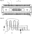
- a shaver and/or trimmer 1 may comprise a cutter head 2 with a cutter system 3.
- the cutter head 2 may be attached to a handle 100 of the shaver and/or trimmer 1.
- the shaver and/or trimmer 1 may include an elongated handle 100 accommodating a battery 101, electronic and/or electric components such as a control unit 102, an electric drive motor 103 or a magnetic drive motor and a drive train 104 for transmitting the driving action of the motor to the cutter system at the cutter head 2 which cutter head 2 may be positioned at one end of the elongated handle 100.
- the handle 100 extends substantially along an axis III ( Figure 4 ).
- the cutter system 3 including a pair of cooperating cutting elements 4 and 5 depicted in Figure 3 may be the only cutter system of the cutter head 2 as it is the case with the example shown in Figure 1 .
- the cutter system 3 may be incorporated into a shaver head 2 having other cutter systems such as shear foil cutters, wherein, for example, the cutter system 3 having at least one row of cooperating cutting teeth may be positioned between a pair of shear foil cutters, or, in the alternative, may be positioned in front of such a shear foil cutter.
- the cutter system 3 may include elongated rows of cutting teeth 6 of the outer cutting element 4 and elongated rows of cutting teeth 7 of the inner cutting element 5 which may reciprocate relative to each other along a linear path so as to effect the cutting action by closing the gaps between the teeth and passing over each other.
- a first axis I is shown which is parallel to the teeth 6.
- a second axis II which is perpendicular to the first axis I defines the direction of movement of the inner cutting element 5 with respect to the outer cutting element 4.
- the cutter system 3 also may include cutting teeth 6 and 7 which are aligned along a circle and/or are arranged radially.
- Such rotatory cutting elements may have cutting teeth projecting substantially radially, wherein the cutting elements may be driven to rotate relative to each other and/or to rotatorily oscillate relative to each other.
- the cutting action is basically similar to reciprocating cutting elements as the radially extending teeth, when rotating and/or rotatorily oscillating, cyclically close and reopen the gap between neighboring teeth and pass over each other like a scissor.
- the drive system may include a motor the shaft of which may rotate an eccentric drive pin which is received between the channel-like contours of a driver which is connected to one of the cutting elements 5 which is caused to reciprocate due to the engagement of the rotating eccentric drive pin with the contours of said driver.
- the cooperating cutting elements 4 and 5 basically may have - at least roughly - a plate-shaped configuration, wherein each cutting element 4 and 5 includes two rows of cutting teeth 6 and 7 which may be arranged at opposite longitudinal sides of the plate-like cutting elements 4 and 5.
- the cutting elements 4 and 5 are supported and positioned with their flat sides lying onto one another. More particularly, the cutting teeth 6 and 7 of the cutting elements 4 and 5 touch each other back to back like the blades of a scissor.
- each field of cutting perforations 8 of the outer cutting element 4 defining a skin contact surface of the cutter system 3 may include at least two rows of perforations 8 which may be formed as small sized through holes having a circular, oval, elliptical or polygonal shape.
- such small sized through holes forming the perforations 8 may have a hexagonal shape, wherein the long axis of such hexagonal through holes, i.e.
- Cutting perforations 9 of the inner cutting element 5 may have an elongate shape as depicted in the example of Figure 3 .
- other shapes of the perforations 9 are suitable to perform cutting or shearing in a scissor-like way when the edges of the perforations 8, 9 of the cooperating cutting elements 4, 5 close the gap between the perforations and pass over each other.
- the perforations 8 are not distributed all over the center section of the skin contact surface, but are arranged in limited areas only. More particularly, the cutting perforations 8 for cutting short hair are restricted to lateral areas of the skin contact surface or skin facing surface of the cutting element 4 following the comb-like cutting teeth 6 when the cutter system 3 is moved along the skin to be shaved with one of the rows of comb-like teeth 6 moving ahead, whereas a middle portion of the skin contact/facing surface defined by the cutting elements in-between said opposite rows of comb-like teeth is unperforated.
- Said elongated unperforated center section of the skin contact surface defined by the outer cutting element 4 may have a size or width which is larger than a size or width of each of said fields of perforations. More particularly, the unperforated center section of the skin contact surface may extend over an area ranging from 100% - 250% or from 110% to 175% of the area defined by each of said fields of perforations. More generally, more than 2/3 or more than 3/4 of the area of the skin contact surface of the cutter element 4 between the comb-like cutting teeth may be unperforated. In other words, only 1/4 - 2/3 of the skin contact surface between the opposite rake-like toothed edges of the cutter system 3 may be perforated. Such limitation of the area of perforations 8 may significantly reduce the friction when the cutting elements 4, 5 move relative to each other.
- the outer cutting element 4 when viewed in a cross section, may have a substantially C-shaped configuration with dog-eared edge portions 10 which are bent away or curved away from the skin contact surface 11 and form holding flanges attached to or fixed to an outer frame portion of a support structure depicted in Figure 3 .
- Said edge portions 10 may be folded back or bent around the edge portions of said outer frame.
- the cutting element 4 may be rigidly or fixedly fastened to said outer frame portions.
- the cutting element 4 may be welded or glued to the outer frame.
- the cutting teeth 6 of the outer cutting element 4 may be formed in the transitional region between the folded back support flanges 10 and the front side of the cutting element 4 defining the skin contact surface 11 of the cutter system 3.
- said outer cutting element 4 may form a C-shaped, plate-like cutting element the edges of which are dog-eared to form limbs bent inwardly like the limbs of a C or a U.
- the transitional edge portion connecting the dog-eared limbs with the central portion of the outer cutting element is contoured or configured to form a row of comb-like teeth 6 for cutting longer stubbles, whereas the central portion 11 of the cutting element 4 is provided with said fields of perforations 8 for cutting short hair.
- Figures 6c and 6d depict the two layers of material folded back-to-back onto each other to form, in cross section, the U-shaped tooth tips. At a position about 0.2 mm away from the tip, these layers together form a substantially square cross section and may be separated by a small gap as shown on the right side tooth in Figure 5d . Proceeding towards the tooth foot, the gap increases as shown at a position about 0.5 mm away from the tip (middle tooth in Figure 5d ) and at a position about 0.75 mm away from the tip (left side tooth in Figure 5d ).
- said outer cutting teeth 6 are formed to have different cross section regions.
- the tooth tip i.e. the free end facing away from the central portion 11, may have a substantially rectangular cross section with rounded edges, whereas the tooth foot, i.e. the opposite end facing towards the central portion 11, has a cross section forming a sharp cutting edge.
- Figure 6a depicts a cross section of the tooth at a position about 0.2 mm away from the tip showing a substantially rectangle configuration in a cross section perpendicular to the first axis I. It is to be noted that this rectangle may be interrupted by a gap, so that a line or gap may be part of the rectangle extending along axis II of Fig 6a (although not visualized in Fig 6a ).
- Figure 6b depicts a cross section of the tooth at a position near the transition to the central portion 11, i.e. the foot of the tooth, showing a substantially concave surface facing towards the inner cutting element 5 with a sharp cutting edge with the planar side facing away from the inner cutting element 5, i.e. the skin facing side, in Fig. 6b the lower side, is smooth and flat.
- the tooth 6 has a flat tip compared with the typically rounded tip ( Figure 8b ) of known trimmers or shavers.
- FIGs 7a and 7b depict a pair of outer cutter teeth 6 in contact with the skin during use of the cutter system. While the known cutter teeth 6 with an oval cross section cause a relatively large skin bulge 20 ( Figure 7b ) as the cutter system is pressed into contact with the skin during operation, the skin bulge 20 is smaller and more evenly distributed with the substantially rectangular design according to the present invention ( Figure 7a ).
- the tooth 6 of the outer cutting element 4 as shown in Figure 5b may have a width at the position 0.2 mm away from the tip of 405+/-25 ⁇ m.
- the pitch between two adjacent teeth 6 may be 730 ⁇ m, which leads to a ratio between tooth width and the opening slot between adjacent teeth of about 4:3. This prevents the tooth tip from going into hair follicles.
- the thickness of the comb-like cutting teeth 6, when viewed in a cross section of the C-shaped cutting element as shown in Figures 5f and 6a , may be less than 300 % or less than 250 % of the thickness of the material forming the center section and/or dog-eared flange of the cutting element.
- the thickness of the teeth 6 is the vertical dimension thereof and corresponds to the height of the tooth tips.
- the teeth when the C-shaped cutting element 4 is made from a sheet-like material having a sheet thickness of 0.15 mm, the teeth may have a thickness of less than 0.5 mm and/or ranging from e.g. 0.2 mm or 0.24 mm or 0.3 mm to 0.5 mm, for example from 0.35 mm to 0.45 mm.
- the C-shaped cutting element 4 may be made from a sheet material having a substantially constant thickness.
- the dog-eared flanges 10 may have the same material thickness as the center section 11.
- said tooth tips of the comb-like cutting teeth may have a radius of curvature of less than 0.25 mm.
- the C-shaped cutting element may be formed from a metal sheet, in particular from a spring steel sheet, wherein a spring steel having a tensile strength of more than 500 N/mm 2 or more than 750 N/mm 2 may be used.
- the tooth tip should have a flat line 12 contacting the skin with a small radius at the edges, whereas the tooth foot should have a sharp cutting edge.
- the small radius may be generated by etching and bending a metal strip.
- the tooth is manufactured by two side etching. As there is no cutting event in this area the cross section of the tooth 6 could be square with a small radius at the edges.
- the tooth is manufactured by one side etching to generate sharp edge for cutting.
Landscapes
- Life Sciences & Earth Sciences (AREA)
- Forests & Forestry (AREA)
- Engineering & Computer Science (AREA)
- Mechanical Engineering (AREA)
- Dry Shavers And Clippers (AREA)
Priority Applications (5)
| Application Number | Priority Date | Filing Date | Title |
|---|---|---|---|
| EP21185864.2A EP4119312A1 (de) | 2021-07-15 | 2021-07-15 | Schneidsystem für einen elektrischen barttrimmer |
| US17/864,525 US20230019742A1 (en) | 2021-07-15 | 2022-07-14 | Cutter system for an electric beard trimmer |
| EP22185001.9A EP4119313A1 (de) | 2021-07-15 | 2022-07-14 | Schneidersystem für einen elektrischen barttrimmer |
| PCT/IB2022/056507 WO2023286011A1 (en) | 2021-07-15 | 2022-07-14 | Cutter system for an electric beard trimmer |
| CN202280049368.XA CN117729989A (zh) | 2021-07-15 | 2022-07-14 | 用于电动胡须修剪器的切割器系统 |
Applications Claiming Priority (1)
| Application Number | Priority Date | Filing Date | Title |
|---|---|---|---|
| EP21185864.2A EP4119312A1 (de) | 2021-07-15 | 2021-07-15 | Schneidsystem für einen elektrischen barttrimmer |
Publications (1)
| Publication Number | Publication Date |
|---|---|
| EP4119312A1 true EP4119312A1 (de) | 2023-01-18 |
Family
ID=76942908
Family Applications (2)
| Application Number | Title | Priority Date | Filing Date |
|---|---|---|---|
| EP21185864.2A Pending EP4119312A1 (de) | 2021-07-15 | 2021-07-15 | Schneidsystem für einen elektrischen barttrimmer |
| EP22185001.9A Pending EP4119313A1 (de) | 2021-07-15 | 2022-07-14 | Schneidersystem für einen elektrischen barttrimmer |
Family Applications After (1)
| Application Number | Title | Priority Date | Filing Date |
|---|---|---|---|
| EP22185001.9A Pending EP4119313A1 (de) | 2021-07-15 | 2022-07-14 | Schneidersystem für einen elektrischen barttrimmer |
Country Status (4)
| Country | Link |
|---|---|
| US (1) | US20230019742A1 (de) |
| EP (2) | EP4119312A1 (de) |
| CN (1) | CN117729989A (de) |
| WO (1) | WO2023286011A1 (de) |
Families Citing this family (4)
| Publication number | Priority date | Publication date | Assignee | Title |
|---|---|---|---|---|
| EP3854540A1 (de) | 2020-01-23 | 2021-07-28 | Braun GmbH | Elektrischer bartschneider |
| EP3854541A1 (de) | 2020-01-23 | 2021-07-28 | Braun GmbH | Elektrischer bartschneider |
| EP3854542B1 (de) * | 2020-01-23 | 2023-12-13 | Braun GmbH | Elektrischer bartschneider |
| EP3854538A1 (de) | 2020-01-23 | 2021-07-28 | Braun GmbH | Elektrischer bartschneider |
Citations (10)
| Publication number | Priority date | Publication date | Assignee | Title |
|---|---|---|---|---|
| US2036557A (en) * | 1934-01-24 | 1936-04-07 | William G Viall | Shaving instrument |
| US2298962A (en) * | 1939-05-10 | 1942-10-13 | Thomas J Murphy | Dry shaver |
| FR910028A (fr) * | 1944-04-05 | 1946-05-24 | Tête interchangeable pour rasoir mécanique | |
| GB719005A (en) * | 1951-10-17 | 1954-11-24 | Mariano De Paoli | Improvements in hair clippers |
| DE102007023362A1 (de) * | 2007-05-18 | 2008-11-20 | Braun Gmbh | Schneideinrichtung zum Schneiden von Haaren |
| DE102007050379A1 (de) * | 2007-10-22 | 2009-04-23 | Braun Gmbh | Haartrimmer |
| EP2425938B1 (de) | 2010-09-03 | 2014-02-26 | Braun GmbH | Rasierkopf mit mehreren Rasiereinheiten |
| EP2747958B1 (de) | 2011-11-17 | 2016-09-07 | Koninklijke Philips N.V. | Hautschutzvorrichtung für haarschneidevorrichtung |
| US20170050326A1 (en) | 2015-08-20 | 2017-02-23 | Specialife (Zhuhai) Co., Ltd. | Personal care trimmer having ultrathin fixed blade and manufacturing method for ultrathin fixed blade |
| WO2018157113A1 (en) * | 2017-02-27 | 2018-08-30 | Spectrum Brands, Inc. | Electric handheld hair trimmer with blade guard |
Family Cites Families (2)
| Publication number | Priority date | Publication date | Assignee | Title |
|---|---|---|---|---|
| US2102529A (en) * | 1935-02-07 | 1937-12-14 | Clipshave Inc | Hair clipper |
| EP2857158B1 (de) * | 2013-10-01 | 2017-05-10 | Koninklijke Philips N.V. | Klingensatz und Haarschneidegerät |
-
2021
- 2021-07-15 EP EP21185864.2A patent/EP4119312A1/de active Pending
-
2022
- 2022-07-14 WO PCT/IB2022/056507 patent/WO2023286011A1/en active Application Filing
- 2022-07-14 US US17/864,525 patent/US20230019742A1/en active Pending
- 2022-07-14 EP EP22185001.9A patent/EP4119313A1/de active Pending
- 2022-07-14 CN CN202280049368.XA patent/CN117729989A/zh active Pending
Patent Citations (10)
| Publication number | Priority date | Publication date | Assignee | Title |
|---|---|---|---|---|
| US2036557A (en) * | 1934-01-24 | 1936-04-07 | William G Viall | Shaving instrument |
| US2298962A (en) * | 1939-05-10 | 1942-10-13 | Thomas J Murphy | Dry shaver |
| FR910028A (fr) * | 1944-04-05 | 1946-05-24 | Tête interchangeable pour rasoir mécanique | |
| GB719005A (en) * | 1951-10-17 | 1954-11-24 | Mariano De Paoli | Improvements in hair clippers |
| DE102007023362A1 (de) * | 2007-05-18 | 2008-11-20 | Braun Gmbh | Schneideinrichtung zum Schneiden von Haaren |
| DE102007050379A1 (de) * | 2007-10-22 | 2009-04-23 | Braun Gmbh | Haartrimmer |
| EP2425938B1 (de) | 2010-09-03 | 2014-02-26 | Braun GmbH | Rasierkopf mit mehreren Rasiereinheiten |
| EP2747958B1 (de) | 2011-11-17 | 2016-09-07 | Koninklijke Philips N.V. | Hautschutzvorrichtung für haarschneidevorrichtung |
| US20170050326A1 (en) | 2015-08-20 | 2017-02-23 | Specialife (Zhuhai) Co., Ltd. | Personal care trimmer having ultrathin fixed blade and manufacturing method for ultrathin fixed blade |
| WO2018157113A1 (en) * | 2017-02-27 | 2018-08-30 | Spectrum Brands, Inc. | Electric handheld hair trimmer with blade guard |
Also Published As
| Publication number | Publication date |
|---|---|
| WO2023286011A1 (en) | 2023-01-19 |
| US20230019742A1 (en) | 2023-01-19 |
| EP4119313A1 (de) | 2023-01-18 |
| CN117729989A (zh) | 2024-03-19 |
Similar Documents
| Publication | Publication Date | Title |
|---|---|---|
| EP4119312A1 (de) | Schneidsystem für einen elektrischen barttrimmer | |
| US11633868B2 (en) | Electric beard trimmer | |
| CN113618788B (zh) | 电动胡须修剪器 | |
| CN115515767A (zh) | 电动胡须修剪器 | |
| CN113618789B (zh) | 电动胡须修剪器 | |
| EP3907043B1 (de) | Elektrischer bartschneider | |
| US11731294B2 (en) | Electric beard trimmer | |
| US20210229304A1 (en) | Electric beard trimmer |
Legal Events
| Date | Code | Title | Description |
|---|---|---|---|
| PUAI | Public reference made under article 153(3) epc to a published international application that has entered the european phase |
Free format text: ORIGINAL CODE: 0009012 |
|
| STAA | Information on the status of an ep patent application or granted ep patent |
Free format text: STATUS: THE APPLICATION HAS BEEN PUBLISHED |
|
| AK | Designated contracting states |
Kind code of ref document: A1 Designated state(s): AL AT BE BG CH CY CZ DE DK EE ES FI FR GB GR HR HU IE IS IT LI LT LU LV MC MK MT NL NO PL PT RO RS SE SI SK SM TR |
|
| P01 | Opt-out of the competence of the unified patent court (upc) registered |
Effective date: 20230430 |
|
| STAA | Information on the status of an ep patent application or granted ep patent |
Free format text: STATUS: REQUEST FOR EXAMINATION WAS MADE |
|
| 17P | Request for examination filed |
Effective date: 20230718 |
|
| RBV | Designated contracting states (corrected) |
Designated state(s): AL AT BE BG CH CY CZ DE DK EE ES FI FR GB GR HR HU IE IS IT LI LT LU LV MC MK MT NL NO PL PT RO RS SE SI SK SM TR |