EP4119087B1 - Optischer marker zur positionierung eines medizinischen instruments und medizinische instrumentenanordnung - Google Patents
Optischer marker zur positionierung eines medizinischen instruments und medizinische instrumentenanordnung Download PDFInfo
- Publication number
- EP4119087B1 EP4119087B1 EP21789019.3A EP21789019A EP4119087B1 EP 4119087 B1 EP4119087 B1 EP 4119087B1 EP 21789019 A EP21789019 A EP 21789019A EP 4119087 B1 EP4119087 B1 EP 4119087B1
- Authority
- EP
- European Patent Office
- Prior art keywords
- medical device
- optical marker
- optical
- base
- feature points
- Prior art date
- Legal status (The legal status is an assumption and is not a legal conclusion. Google has not performed a legal analysis and makes no representation as to the accuracy of the status listed.)
- Active
Links
Images


Classifications
-
- A—HUMAN NECESSITIES
- A61—MEDICAL OR VETERINARY SCIENCE; HYGIENE
- A61B—DIAGNOSIS; SURGERY; IDENTIFICATION
- A61B90/00—Instruments, implements or accessories specially adapted for surgery or diagnosis and not covered by any of the groups A61B1/00 - A61B50/00, e.g. for luxation treatment or for protecting wound edges
- A61B90/39—Markers, e.g. radio-opaque or breast lesions markers
-
- A—HUMAN NECESSITIES
- A61—MEDICAL OR VETERINARY SCIENCE; HYGIENE
- A61B—DIAGNOSIS; SURGERY; IDENTIFICATION
- A61B17/00—Surgical instruments, devices or methods
- A61B17/34—Trocars; Puncturing needles
-
- A—HUMAN NECESSITIES
- A61—MEDICAL OR VETERINARY SCIENCE; HYGIENE
- A61B—DIAGNOSIS; SURGERY; IDENTIFICATION
- A61B34/00—Computer-aided surgery; Manipulators or robots specially adapted for use in surgery
- A61B34/20—Surgical navigation systems; Devices for tracking or guiding surgical instruments, e.g. for frameless stereotaxis
-
- A—HUMAN NECESSITIES
- A61—MEDICAL OR VETERINARY SCIENCE; HYGIENE
- A61B—DIAGNOSIS; SURGERY; IDENTIFICATION
- A61B90/00—Instruments, implements or accessories specially adapted for surgery or diagnosis and not covered by any of the groups A61B1/00 - A61B50/00, e.g. for luxation treatment or for protecting wound edges
- A61B90/10—Instruments, implements or accessories specially adapted for surgery or diagnosis and not covered by any of the groups A61B1/00 - A61B50/00, e.g. for luxation treatment or for protecting wound edges for stereotaxic surgery, e.g. frame-based stereotaxis
- A61B90/11—Instruments, implements or accessories specially adapted for surgery or diagnosis and not covered by any of the groups A61B1/00 - A61B50/00, e.g. for luxation treatment or for protecting wound edges for stereotaxic surgery, e.g. frame-based stereotaxis with guides for needles or instruments, e.g. arcuate slides or ball joints
-
- A—HUMAN NECESSITIES
- A61—MEDICAL OR VETERINARY SCIENCE; HYGIENE
- A61B—DIAGNOSIS; SURGERY; IDENTIFICATION
- A61B90/00—Instruments, implements or accessories specially adapted for surgery or diagnosis and not covered by any of the groups A61B1/00 - A61B50/00, e.g. for luxation treatment or for protecting wound edges
- A61B90/90—Identification means for patients or instruments, e.g. tags
- A61B90/94—Identification means for patients or instruments, e.g. tags coded with symbols, e.g. text
- A61B90/96—Identification means for patients or instruments, e.g. tags coded with symbols, e.g. text using barcodes
-
- A—HUMAN NECESSITIES
- A61—MEDICAL OR VETERINARY SCIENCE; HYGIENE
- A61B—DIAGNOSIS; SURGERY; IDENTIFICATION
- A61B17/00—Surgical instruments, devices or methods
- A61B2017/00831—Material properties
- A61B2017/00862—Material properties elastic or resilient
-
- A—HUMAN NECESSITIES
- A61—MEDICAL OR VETERINARY SCIENCE; HYGIENE
- A61B—DIAGNOSIS; SURGERY; IDENTIFICATION
- A61B17/00—Surgical instruments, devices or methods
- A61B2017/00831—Material properties
- A61B2017/00902—Material properties transparent or translucent
-
- A—HUMAN NECESSITIES
- A61—MEDICAL OR VETERINARY SCIENCE; HYGIENE
- A61B—DIAGNOSIS; SURGERY; IDENTIFICATION
- A61B17/00—Surgical instruments, devices or methods
- A61B17/34—Trocars; Puncturing needles
- A61B17/3403—Needle locating or guiding means
- A61B2017/3405—Needle locating or guiding means using mechanical guide means
- A61B2017/3407—Needle locating or guiding means using mechanical guide means including a base for support on the body
-
- A—HUMAN NECESSITIES
- A61—MEDICAL OR VETERINARY SCIENCE; HYGIENE
- A61B—DIAGNOSIS; SURGERY; IDENTIFICATION
- A61B34/00—Computer-aided surgery; Manipulators or robots specially adapted for use in surgery
- A61B34/20—Surgical navigation systems; Devices for tracking or guiding surgical instruments, e.g. for frameless stereotaxis
- A61B2034/2046—Tracking techniques
- A61B2034/2055—Optical tracking systems
-
- A—HUMAN NECESSITIES
- A61—MEDICAL OR VETERINARY SCIENCE; HYGIENE
- A61B—DIAGNOSIS; SURGERY; IDENTIFICATION
- A61B34/00—Computer-aided surgery; Manipulators or robots specially adapted for use in surgery
- A61B34/20—Surgical navigation systems; Devices for tracking or guiding surgical instruments, e.g. for frameless stereotaxis
- A61B2034/2046—Tracking techniques
- A61B2034/2065—Tracking using image or pattern recognition
-
- A—HUMAN NECESSITIES
- A61—MEDICAL OR VETERINARY SCIENCE; HYGIENE
- A61B—DIAGNOSIS; SURGERY; IDENTIFICATION
- A61B90/00—Instruments, implements or accessories specially adapted for surgery or diagnosis and not covered by any of the groups A61B1/00 - A61B50/00, e.g. for luxation treatment or for protecting wound edges
- A61B90/39—Markers, e.g. radio-opaque or breast lesions markers
- A61B2090/3937—Visible markers
-
- A—HUMAN NECESSITIES
- A61—MEDICAL OR VETERINARY SCIENCE; HYGIENE
- A61B—DIAGNOSIS; SURGERY; IDENTIFICATION
- A61B90/00—Instruments, implements or accessories specially adapted for surgery or diagnosis and not covered by any of the groups A61B1/00 - A61B50/00, e.g. for luxation treatment or for protecting wound edges
- A61B90/39—Markers, e.g. radio-opaque or breast lesions markers
- A61B2090/3983—Reference marker arrangements for use with image guided surgery
Definitions
- the present invention relates to the technical field of medical devices, and in particular to an optical marker for positioning a medical device, and a medical device assembly.
- a medical device In a process of medical clinical practice, it is often need to probe a medical device into a human body to perform some kind of interventional operation. For example, percutaneous puncture from the outside of the body may be performed to obtain a small-sample of a diseased tissue in the human body.
- percutaneous puncture from the outside of the body may be performed to obtain a small-sample of a diseased tissue in the human body.
- there are mature device solutions that can meet clinical needs in the field of diseases related to natural orifices of the human body, such as heart and blood vessels, digestive tracts and respiratory tracts.
- a surgical channel needs to be established.
- a minimally invasive intervention may be limited by surgical positioning and navigation.
- the distal end of the medical device is invisible to the operator. In this type of operation, accurate positioning and navigation for the medical device is very important.
- the existing optical feature points used for positioning the medical device are usually arranged in a planar manner, which may affect the accuracy of surgical positioning and cannot meet needs of medical practice.
- the application discloses an image guidance system for tracking a surgical instrument during a surgical procedure.
- the image guidance system comprises a tracking assembly.
- the tracking assembly includes a pattern display surface.
- a tracking pattern is disposed or formed on the pattern display surface.
- the tracking pattern is an optically visible pattern that is configured to provide visual reference points for externally mounted cameras to detect for use by a computer system to track the position and movement of the tracking assembly, and, thus, the oral fixture.
- optical marker is disclosed in document CN107961074 , the optical marker having a base in the shape of a bowl, with a concave inner surface and a convex outer surface and a reflective coating on the convex outer surface.
- an optical marker for positioning a medical device outside a body comprising: a base; anda connecting portion connected to the base and used for connecting to a to-be-positioned portion of the medical device,the optical marker characterized in that :the base is in a shape of a bowl and includes a concave inner surface and a convex outer surface, non-coplanar optical marks are provided on and visible on the concave inner surface and/or the convex outer surface for recognizing the optical marker by a positioning device and determining a position of the medical device based on the recognized optical marker, wherein:the base is made of a transparent material, and the inner surface or the outer surface is covered with a non-transparent optical mark layer provided with the optical marks; orthe base is made of a non-transparent material, and the optical marks are on both the inner surface and the outer surface,such that from a direction of the inner surface or a direction of the outer surface of the bowl, position information
- a rim of the bowl is a proximal end of the optical marker relative to a bottom of the bowl.
- the thickness of the wall of the bowl is uniform.
- the optical mark(s) comprise a plurality of feature points, and at least some of the plurality of feature points are located on a concentric circle and are distributed in non-central symmetry.
- a rim of the bowl is provided with a flanging extending outwards.
- the connecting portion is provided in a central area of the base.
- the center of the connecting portion is provided with a mounting hole for receiving a mounting fitting portion of the medical device.
- At least a part of the connecting portion provided with the mounting hole is made of an elastic material for interference fitting with the mounting fitting portion of the medical device.
- the mounting hole is a threaded hole for screw connection with the mounting fitting portion of the medical device.
- the connecting portion is provided with a claw, wherein the claw is used to clamp the mounting fitting portion of the medical device.
- a medical device assembly comprising a medical device, and further comprising the optical marker mentioned above.
- the medical device is a puncture needle.
- the base provided with the optical mark(s) has a non-planar structure, can increase the recognizable angle of a medical device and improve the recognition accuracy and stability.
- An interventional operation inside the body in the medical field requires accurate positioning in three dimensions and six degrees of freedom.
- the positioning of a medical device such as a puncture needle requires to be specially optimized for the situation that the medical device is rotated at a large angle relative to a camera of a video acquisition device, so as to ensure that the medical device may be accurately positioned during the whole process of the interventional operation.
- optical feature points are usually arranged in a planar manner, for example, in a form of a Quick Response (QR) code.
- QR Quick Response
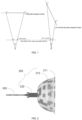
- FIG. 1 is a schematic diagram of the recognizability of feature points on a flat plate at different angles.
- point C represents the position of the video acquisition device.
- a more ideal optical marker is required mainly based on the above reason.
- the video acquisition device located outside the body may be used to capture a video of the medical device in real time, and the video includes an optical marker fixed to the medical device.
- the video acquisition device may be a camera located outside the body, for example, a head-mounted camera for the user. In this manner, the capture angle of the video acquisition device is consistent with the observation direction of the user.
- a positioning device is used to recognize an optical mark(s) provided on the optical marker in the video, that is, to recognize the optical mark(s) in each frame of the video.
- the recognition operation may be based on an existing mature image recognition algorithm, such as a recognition method based on a texture feature, frequency domain analysis, machine learning and so on.
- the positioning device is further used to determine a current pose of the optical marker based on the recognized optical mark(s), and then a current pose of the medical device is determined based on the positional relationship between the optical marker and the medical device.
- FIG. 2 is a side view of an optical marker 200 connected with a medical device 500 according to an embodiment of the present disclosure.
- the optical marker 200 may be fixed to the medical device 500, thereby forming a relatively fixed positional relationship with the medical device 500.
- the medical device 500 may be positioned by recognizing the optical marker 200.
- the optical marker 200 includes a base 210 and a connecting portion 220 connected to the base 210.
- the connecting portion 220 is used to connect to the medical device 500.
- the connecting portion 220 is used to connect to a portion close to a proximal end of the medical device 500.
- the proximal end of a component refers to an end of the component that is closer to a user operating the component; an end of the component that is further away from the user operating the component refers to a distal end.
- the video acquisition device is usually in the same direction relative to the medical device as the user. As a result, the proximal end is closer to the video acquisition device than the distal end.
- the base 210 of the optical marker 200 has a concave.
- the concave faces the video acquisition device.
- the concave is provided with an optical mark(s), and the optical mark(s) are visible on the entire surface of the concave, which is as shown as the texture on the base 210 in FIG. 2 .
- the optical mark(s) are used to recognize the optical marker by a positioning device and to determine a position of the medical device 500 based on the recognized optical marker.
- the optical mark(s) are not coplanar, in other words, not all (parts of) optical mark(s) are on the same plane. However, there may be some of the optical marks that are coplanar.
- the optical mark(s) may include a plurality of feature points. The recognition and positioning of the optical marker based on the feature points requires a little calculation and is easy to implement.
- the optical mark(s) are located on a curved surface where the concave is located.
- the base 210 may also have a convex provided with a non-coplanar optical mark(s) on the surface.
- the convex faces the video acquisition device.
- the concave and/or the convex on the base 210 can significantly increase the recognizable area of the surface of the base 210 on the premise of keeping the overall dimension of the base unchanged, thereby improving the accuracy of positioning of the medical device.
- the optical marker is located outside the body and can be used in combination with a disposable sterile interventional consumable.
- the sterility requirement of the optical marker itself is lower and the optical marker may be reused, thereby reducing the use cost.
- the optical marker has no requirements on the shape of the medical device, and has a strong universality.
- a spatial position of a three-dimensional object may be determined based on three or more non-collinear feature points thereof.
- recognition of the pose of the object based on a video is affected by factors such as motion blur, optical distortion, chromatic dispersion, occlusion, uneven illumination and so on.
- a flat plate-shaped base and a bowl-shaped base are taken as examples respectively to illustrate the significant increase in the number of recognizable feature points of the bowl-shaped base. To simplify calculation, it is assumed that the bowl is in the shape of a hemisphere.
- an included angle ⁇ is formed between the line connecting a feature point P1 on the optical marker and a position point C where the camera of the video acquisition device is located and the line connecting a feature point P2 adjacent to the feature point P1 and the position point C (referred to as "field angle of the feature points").
- Recognizability of the feature points depends on the distance between the pixel points projected by the feature points of an object on a CCD (or CMOS) plane of the camera after passing through an optical lens.
- a projection distance of the two feature points on the plane of the camera is directly proportional to the field angle of the feature points.
- the field angle of the feature points may be directly used as a determination object.
- ⁇ T referred to as the "minimum visible field angel
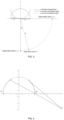
- FIG. 3 is a schematic diagram of a coordinate system for calculating the total numbers of effective feature points of optical markers of different shapes according to embodiments of the present disclosure.
- a two-dimensional Cartesian coordinate system is constructed by taking a straight line where a flat plate-shaped base is located as the X-axis, wherein the origin of the Cartesian coordinate system is the midpoint of the flat plate-shaped base, and the lower surface of the flat plate-shaped base facing a camera is provided with an optical mark(s).
- the X-axis of the Cartesian coordinate system is the straight line connecting the two endpoints of the semi-circular arc, and the origin is a midpoint of the line connecting the two endpoints of the semi-circular arc.
- the X-axis of the Cartesian coordinate system is a straight line passing through the midpoint of the top of the semi-circular arc and perpendicular to the connecting line of the two endpoints of the semi-circular arc, and the origin is the midpoint of the top of the semi-circular arc. It is assumed that both the front side of the bowl-shaped base facing the camera and the back side facing away from the camera are provided with the optical mark(s).
- n points are taken as observation points on average.
- new feature points are set at every interval of an arc length d along the direction of the arc, until the position of the next feature point is about to exceed the range of the semi-circular arc.
- P i x ⁇ cos d ⁇ i D ⁇ D
- P i y D ⁇ sin d ⁇ i D ⁇ D .
- new feature points are set at every interval of an arc length d along the direction of the arc, until the position of the next feature point is about to exceed the range of the semi-circular arc.
- P i x ⁇ cos d ⁇ i D ⁇ D
- P i y sin d ⁇ i D ⁇ D .
- ⁇ ⁇ i arccos d 2 i 2 + d d ⁇ 2 R ⁇ sin ⁇ i + R R ⁇ d ⁇ sin ⁇ ⁇ dR ⁇ cos ⁇ .
- the feature points of the flat plate-shaped base have no occlusion problem for all observation points, and a result may be obtained directly based on the calculation formula of the number of effective feature points M ⁇ .
- FIG. 4 shows the visibility of an optical marker according to an embodiment of the present disclosure.
- a dashed arc an arc between point A and point B
- FIG. 5 shows the visibility of an optical marker according to another embodiment of the present disclosure.
- a dashed arc an arc on the left of point A
- a x ⁇ b ⁇ b 2 ⁇ 4 ac 2 a ;
- a y C y D ⁇ C x A x C y + D .
- the feature point is regarded as the non-occluded point.
- FIG. 6 is a schematic diagram of a concave hemisphere base according to an embodiment of the present disclosure. From a semi-circular arc with the center of the hemisphere as the center to both sides thereof, a new semi-circular arc is set at every interval of a distance d as shown in Figure 6 . When calculating the number of effective feature points of the new semi-circular arc, in order to simplify the calculation, an observation point where a camera is located and the arc are translated by the distance d in the same direction to obtain an approximate result.
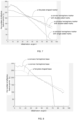
- FIGS. 7, 8 and 9 are schematic diagrams that respectively show calculation results of the numbers of effective feature points of a flat plate-shaped base, a concave hemisphere base, and a convex hemisphere base at different observation angles according to embodiments of the present disclosure.
- the vertical axis in the figures represents the total number of effective feature points, and an the horizontal axis represents the observation angle.
- D 25 mm
- d 3 mm
- ⁇ T 0.2°
- R 200 mm.
- FIG. 10 is a schematic diagram that shows calculation results of the number of effective feature points of a flat plate-shaped base, a concave hemisphere base, and a convex hemisphere base at different observation angles according to other embodiments of the present disclosure.
- a field angel of a camera is 60°
- a pixel value thereof is 10 million (3600*2800)
- D 25 mm
- d 2 mm
- R 300 mm.
- the base is not a flat plate-shape base such as a concave hemisphere base or a convex hemisphere base, it can avoid complete failure of all feature points that cannot be simultaneously distinguished by the camera in a rotation process of the optical marker.
- the optical markers with the concave hemisphere base or the convex hemisphere base can ensure a stable and larger total number of recognizable points within the moving range of the medical device, and at the same time, more recognizable points having a stabler total number can be obtained in the range from 0° to 30° and from 60° to 90° than those of a planar optical marker. Therefore, it is very suitable for positioning the medical device within this range that there is a concave or a convex on the base.
- the base 210 is in the shape of a bowl, which is approximately the shape of a hollow hemisphere.
- both the inner surface and the outer surface of the bowl may be provided with the optical mark(s).
- the base 210 in such a shape can ensure the accuracy of positioning and navigating the medical device based on the optical marker.
- the base 210 is hollow, less material is used and production cost is lower.
- the base 210 is light in weight, thereby avoiding the adverse effect on an operator and on positioning the medical device due to its gravity.
- the puncture needle deflects in the body of the patient due to the influence of the it's gravity and that the accuracy of positioning is affected.
- the shape of a bowl is a more regular shape, which facilitates later positioning calculation.
- the base may further be in other shapes, such as a saddle shape or a polyhedron, as long as the base has a concave or a convex, so that the optical mark(s) on it are not coplanar.
- Such shapes are not part of the present invention.
- the more complex the shape of the base is the greater the amount of the positioning calculation is, and therefore, there are higher requirements for the accuracy and speed of the calculation.
- the rim of the bowl is the proximal end of the optical marker relative to the bottom of the bowl.
- the bowl is made of a transparent material, and the thickness of the wall of the bowl is uniform.
- the inner surface or outer surface of the bowl is covered with an optical mark layer where is provided with an optical mark(s) and is non-transparent. It is assumed that the optical mark layer is covered on the inner surface of the bowl, since the bowl is made of the transparent material, whether from the direction of the inner surface of the bowl or the direction of the outer surface thereof, position information about the optical mark(s) can be captured. In such a way, the consistency of the optical mark(s) on the inner and outer surfaces is ensured, which is convenient for subsequent calculation for positioning the medical device.
- the uniform thickness of the wall of the bowl ensures that the optical distortion is less, thus further ensuring the accuracy of positioning the medical device.
- the base of the marker according to the present invention is made of a non-transparent materia
- the inner surface and the outer surface of the bowl are provided with the same or different optical mark(s).
- the base made of the non-transparent material may avoid a positioning error caused by the optical distortion, especially for a video captured from the side by the video acquisition device.
- the optical mark(s) on the base include a plurality of feature points, where at least some of the plurality of feature points are located on a concentric circle and are distributed in a non-central symmetrical manner.
- the feature points for positioning calculation, the amount of the calculation is small, while the calculation is accurate.
- intersection points of line segments of the mark(s) may be used as the feature points.
- FIG. 11 is a front view of the optical marker of the embodiment shown in FIG. 2 .
- feature points 112-117 on the base of the optical marker are located on a concentric circle and are distributed in a non-central symmetrical manner. The feature points are set in such a manner, which can further simplify calculation while ensuring the accuracy of positioning.
- the rim of the bowl is provided with a flanging extending outwards.
- a flanging 211 is provided on the base 210. The flanging can increase a radial support force of the base, and reduce a degree of deformation during hand holding or transportation, thereby ensuring the accuracy of positioning of the medical device.
- the connecting portion of the optical marker is provided in a central area of the base.
- the base 210 is in the shape of a bowl, and the connecting portion 220 is located in the central area of the bottom of the bowl.
- the connecting portion is arranged in the central area of the base, so that during an operation of a user, the user may hold the connecting portion by hand to facilitate the operation.
- the center of the connecting portion is provided with a mounting hole for receiving a mounting fitting portion of the medical device.
- the mounting hole may be a through hole or a non-through hole depending on different application scenarios.
- the puncture needle passes through the mounting hole in the center of the connecting portion 220, so that the optical marker is fixed on the puncture needle.
- the mounting hole is arranging in the center of the connecting portion, which is convenient for the optical marker to be firmly fixed on the medical device, and is also beneficial for the video acquisition device to capture the video of the optical marker from the generally consistent direction, so as to position the medical device more accurately.
- At least a part of the connecting portion provided with the mounting hole is made of an elastic material for interference fitting with the mounting fitting portion of the medical device.
- the puncture needle and the connecting portion 220 are fixed together by interference fit. This manner is simple and is easy to implement; and the cost of the optical marker is lower.
- the mounting hole is a threaded hole for screw connection with the mounting fitting portion of the medical device.
- FIG. 12 is a side view of an optical marker 1200 according to another embodiment of the present disclosure. For conciseness, an optical mark(s) of the optical marker 1200 is not shown therein. As shown in FIG. 12 , the mounting hole of the optical marker 1200 is the threaded hole. The threaded hole facilitates quick installation of the optical marker 1200 on the medical device and quick release of the optical marker 1200 from the medical device, thereby improving user experience.
- the mounting portion of the optical marker is a Luer taper.
- the Luer taper is a standard connector, which may be beneficial for improving the universality of the optical marker and enable the optical marker to be used for more medical devices.
- FIG. 13a and FIG. 13b respectively show a side view and a top view of an optical marker 1300 according to another embodiment of the present disclosure.
- a base 1310 of the optical marker 1300 is in the shape of a bowl.
- an optical mark(s) of the optical marker 1200 is not shown therein.
- a connecting portion 1320 of the optical marker 1300 is provided with a claw 1321.
- the claw 1321 is used to clamp a mounting fitting portion of a medical device. The claw facilitates quick installation of the optical marker 1300 on the medical device and quick release of the optical marker 1300 from the medical device, thereby improving user experience.
- the connecting portion includes a first end portion and a second end portion which are connected to each other.
- the connecting portion 1320 includes a first end portion 1322 and a second end portion 1323.
- One end of the first end portion 1322 is connected to the base 1310, and the other end thereof is connected to the second end portion 1323.
- the second end portion 1323 is used to connect to the mounting fitting portion of the medical device.
- the second end portion 1323 is provided with the claw 1321 for clamping the mounting fitting portion of the medical device.
- the optical marker 1300 may be connected to the side surface of the medical device, and is suitable for an application scenario in which a center line of a visual angle of a video acquisition device has an included angle with an axis of the medical device.
- a medical device assembly includes a medical device and the optical marker.
- the medical device has a larger recognizable angle, higher recognition accuracy, and higher stability.
Landscapes
- Health & Medical Sciences (AREA)
- Life Sciences & Earth Sciences (AREA)
- Surgery (AREA)
- Engineering & Computer Science (AREA)
- Medical Informatics (AREA)
- Veterinary Medicine (AREA)
- Biomedical Technology (AREA)
- Heart & Thoracic Surgery (AREA)
- Nuclear Medicine, Radiotherapy & Molecular Imaging (AREA)
- Molecular Biology (AREA)
- Animal Behavior & Ethology (AREA)
- General Health & Medical Sciences (AREA)
- Public Health (AREA)
- Pathology (AREA)
- Oral & Maxillofacial Surgery (AREA)
- Robotics (AREA)
- Length Measuring Devices By Optical Means (AREA)
- Infusion, Injection, And Reservoir Apparatuses (AREA)
Claims (11)
- Optischer Marker (200, 1200, 1300) zum Positionieren einer medizinischen Vorrichtung (500) außerhalb eines Körpers, umfassend:eine Basis (210, 1210, 1310); undeinen Verbindungsabschnitt (220, 1220, 1320), der mit der Basis (210, 1210, 1310) verbunden ist und zum Verbinden mit einem zu positionierenden Abschnitt der medizinischen Vorrichtung (500) dient,wobei der optische Marker (200, 1200, 1300) dadurch gekennzeichnet ist, dass:
die Basis (210, 1210, 1310) die Form einer Schale aufweist und eine konkave Innenfläche und eine konvexe Außenfläche einschließt, nicht koplanare optische Marker auf der konkaven Innenfläche und/oder der konvexen Außenfläche bereitgestellt und sichtbar sind, um den optischen Marker (200, 1200, 1300) durch eine Positionierungsvorrichtung zu erkennen und eine Position der medizinischen Vorrichtung (500) basierend auf dem erkannten optischen Marker (200, 1200, 1300) zu bestimmen, wobei:die Basis aus einem transparenten Material besteht und die Innenfläche oder die Außenfläche mit einer nicht transparenten optischen Markierungsschicht bedeckt ist, die mit den optischen Markern versehen ist; oderdie Basis aus einem nicht-transparenten Material besteht und die optischen Marker sich sowohl auf der Innenfläche als auch auf der Außenfläche befinden,sodass aus einer Richtung der Innenfläche oder einer Richtung der Außenfläche der Schale Positionsinformationen über die optischen Marker erfasst werden können. - Optische Marker (200, 1200, 1300) nach Anspruch 1, wobei die optischen Marker eine Vielzahl von Merkmalspunkten (112, 113, 114, 115, 116, 117) umfassen und zumindest einige der Vielzahl von Merkmalspunkten (112, 113, 114, 115, 116, 117) auf einem konzentrischen Kreis liegen und nicht rotationssymmetrisch verteilt sind.
- Optischer Marker (200, 1200, 1300) nach Anspruch 1, wobei ein Rand der Schale mit einer nach außen ragenden Bördelung (211) versehen ist.
- Optischer Marker (200, 1200, 1300) nach Anspruch 1, wobei der Verbindungsabschnitt (220, 1220, 1320) in einem zentralen Bereich der Basis (210, 1210, 1310) vorgesehen ist.
- Optischer Marker (200, 1200) nach Anspruch 1, wobei die Mitte des Verbindungsabschnitts (220, 1220) mit einem Montageloch zur Aufnahme eines Montagepassabschnitts der medizinischen Vorrichtung versehen ist.
- Optischer Marker (200) nach Anspruch 5, wobei zumindest ein Teil des mit dem Montageloch versehenen Verbindungsabschnitts (220) aus einem elastischen Material besteht, um mit dem Montagepassungsabschnitt der medizinischen Vorrichtung zusammenzupassen.
- Optischer Marker (1200) nach Anspruch 5, wobei das Montageloch ein Gewindeloch zur Schraubverbindung mit dem Montageanschlussabschnitt der medizinischen Vorrichtung ist.
- Optischer Marker (1300) nach Anspruch 1, wobei der Verbindungsabschnitt (1320) mit einer Klaue (1321) versehen ist, wobei die Klaue (1321) zum Festklemmen eines Montagepassabschnitts der medizinischen Vorrichtung verwendet wird.
- Optischer Marker (1300) nach Anspruch 1, wobei der Verbindungsabschnitt (1320) einen ersten Endabschnitt (1322) und einen zweiten Endabschnitt (1323) umfasst, die miteinander verbunden sind, wobei der erste Endabschnitt (1322) mit der Basis (1310) verbunden ist, ein eingeschlossener Winkel zwischen dem ersten Endabschnitt (1322) und dem zweiten Endabschnitt (1323) vorgesehen ist, und der zweite Endabschnitt (1323) verwendet wird, um einen Montageanschlussabschnitt der medizinischen Vorrichtung zu verbinden.
- Medizinische Vorrichtungsanordnung, umfassend eine medizinische Vorrichtung (500), und dadurch gekennzeichnet, dass sie ferner den optischen Marker (200, 1200, 1300) gemäß einem der Ansprüche 1-9 umfasst.
- Medizinische Vorrichtungsanordnung nach Anspruch 10, wobei die medizinische Vorrichtung (500) eine Punktionsnadel ist.
Applications Claiming Priority (2)
| Application Number | Priority Date | Filing Date | Title |
|---|---|---|---|
| CN202010286335.XA CN112075994B (zh) | 2020-04-13 | 2020-04-13 | 用于定位医疗器械的光学标识物和医疗器械组件 |
| PCT/CN2021/079648 WO2021208636A1 (zh) | 2020-04-13 | 2021-03-09 | 用于定位医疗器械的光学标识物和医疗器械组件 |
Publications (4)
| Publication Number | Publication Date |
|---|---|
| EP4119087A1 EP4119087A1 (de) | 2023-01-18 |
| EP4119087A4 EP4119087A4 (de) | 2023-11-15 |
| EP4119087B1 true EP4119087B1 (de) | 2025-05-07 |
| EP4119087C0 EP4119087C0 (de) | 2025-05-07 |
Family
ID=73734654
Family Applications (1)
| Application Number | Title | Priority Date | Filing Date |
|---|---|---|---|
| EP21789019.3A Active EP4119087B1 (de) | 2020-04-13 | 2021-03-09 | Optischer marker zur positionierung eines medizinischen instruments und medizinische instrumentenanordnung |
Country Status (4)
| Country | Link |
|---|---|
| US (1) | US12127892B2 (de) |
| EP (1) | EP4119087B1 (de) |
| CN (1) | CN112075994B (de) |
| WO (1) | WO2021208636A1 (de) |
Families Citing this family (1)
| Publication number | Priority date | Publication date | Assignee | Title |
|---|---|---|---|---|
| CN112075994B (zh) | 2020-04-13 | 2021-08-31 | 上海复拓知达医疗科技有限公司 | 用于定位医疗器械的光学标识物和医疗器械组件 |
Family Cites Families (16)
| Publication number | Priority date | Publication date | Assignee | Title |
|---|---|---|---|---|
| US20030210812A1 (en) * | 2002-02-26 | 2003-11-13 | Ali Khamene | Apparatus and method for surgical navigation |
| US6978167B2 (en) * | 2002-07-01 | 2005-12-20 | Claron Technology Inc. | Video pose tracking system and method |
| US9867669B2 (en) * | 2008-12-31 | 2018-01-16 | Intuitive Surgical Operations, Inc. | Configuration marker design and detection for instrument tracking |
| CN104053403B (zh) * | 2012-01-18 | 2016-12-21 | 皇家飞利浦有限公司 | 活检期间针路径的超声引导 |
| WO2014145317A1 (en) * | 2013-03-15 | 2014-09-18 | Visualase, Inc. | Surgical device |
| EP3035882B1 (de) * | 2013-08-13 | 2018-03-28 | Brainlab AG | Moiré-markervorrichtung zur medizinischen navigation |
| US9402691B2 (en) * | 2014-09-16 | 2016-08-02 | X-Nav Technologies, LLC | System for determining and tracking movement during a medical procedure |
| WO2017050761A1 (en) * | 2015-09-21 | 2017-03-30 | Navigate Surgical Technologies, Inc. | System and method for determining the three-dimensional location and orientation of identification markers |
| CN105496519B (zh) * | 2015-12-31 | 2018-10-30 | 精微视达医疗科技(武汉)有限公司 | 一种b超引导下的穿刺导航系统 |
| EP3413829B1 (de) * | 2016-02-12 | 2024-05-22 | Intuitive Surgical Operations, Inc. | Systeme zur posenschätzung und kalibrierung von perspektivischen bildgebungssystemen in der bildgeführten chirurgie |
| CA3005502C (en) * | 2016-03-17 | 2021-03-30 | Brainlab Ag | Optical tracking |
| CN107961074A (zh) * | 2016-10-20 | 2018-04-27 | 深圳先进技术研究院 | 用于光学手术导航系统的反光标志体 |
| US11998282B2 (en) * | 2016-12-16 | 2024-06-04 | Intuitive Surgical Operations, Inc. | Systems and methods for teleoperated control of an imaging instrument |
| US20210161553A1 (en) * | 2018-04-12 | 2021-06-03 | Howard University | Surgical instrument stabilization device |
| CN112075994B (zh) | 2020-04-13 | 2021-08-31 | 上海复拓知达医疗科技有限公司 | 用于定位医疗器械的光学标识物和医疗器械组件 |
| US11974885B2 (en) * | 2020-10-01 | 2024-05-07 | National Guard Health Affairs | Neuropilot manual neural navigation device |
-
2020
- 2020-04-13 CN CN202010286335.XA patent/CN112075994B/zh active Active
-
2021
- 2021-03-09 EP EP21789019.3A patent/EP4119087B1/de active Active
- 2021-03-09 US US17/996,145 patent/US12127892B2/en active Active
- 2021-03-09 WO PCT/CN2021/079648 patent/WO2021208636A1/zh not_active Ceased
Also Published As
| Publication number | Publication date |
|---|---|
| CN112075994A (zh) | 2020-12-15 |
| WO2021208636A1 (zh) | 2021-10-21 |
| CN112075994B (zh) | 2021-08-31 |
| EP4119087A1 (de) | 2023-01-18 |
| EP4119087C0 (de) | 2025-05-07 |
| US12127892B2 (en) | 2024-10-29 |
| EP4119087A4 (de) | 2023-11-15 |
| US20230210629A1 (en) | 2023-07-06 |
Similar Documents
| Publication | Publication Date | Title |
|---|---|---|
| EP3454738B1 (de) | Lokalisierte optische kohärenztomografiebilder für augenchirurgische eingriffe | |
| KR101572487B1 (ko) | 환자와 3차원 의료영상의 비침습 정합 시스템 및 방법 | |
| CN106952347B (zh) | 一种基于双目视觉的超声手术辅助导航系统 | |
| CN110279467A (zh) | 光学定位下的超声图像与穿刺活检针的术中信息融合方法 | |
| US7677801B2 (en) | Non-invasive method and apparatus to locate incision site for spinal surgery | |
| CN110236674A (zh) | 一种基于结构光扫描的肝脏手术导航方法及系统 | |
| JP2001061861A (ja) | 画像撮影手段を備えたシステムおよび医用ワークステーション | |
| JP2002102251A (ja) | 患者への医学的侵襲に関するデータを可視化するための可視化装置及び方法 | |
| US10682126B2 (en) | Phantom to determine positional and angular navigation system error | |
| US10383692B1 (en) | Surgical instrument guidance system | |
| TW201106916A (en) | Omni-directional position surgical guide instrument and omni-directional position unit structure thereof | |
| KR20190056637A (ko) | 정위 장치, 정위 시스템, 및 정위 시스템을 이용하는 정합 방법 | |
| EP4119087B1 (de) | Optischer marker zur positionierung eines medizinischen instruments und medizinische instrumentenanordnung | |
| CN112022304A (zh) | 一种无框导航下的可视穿刺系统 | |
| CN108113629B (zh) | 硬管内窥镜旋转角度测量方法和装置 | |
| KR101862133B1 (ko) | 바늘 삽입형 중재시술 로봇 장치 | |
| CN201085689Y (zh) | 一种标定模 | |
| CN209884326U (zh) | 一种用于手术导航的定位标记装置及配准系统 | |
| CN111887988A (zh) | 一种微创介入手术导航机器人的定位方法及其装置 | |
| CN109938809A (zh) | 一种目标点定位导航系统和方法 | |
| WO2009107703A1 (ja) | 体内挿入器具の種類を識別可能な手術支援システム | |
| CN210019641U (zh) | 配准骨钉及配准系统 | |
| CN120000330A (zh) | 一种配准探针及配准方法 | |
| JP2009201618A (ja) | 体内挿入器具の種類を識別可能な手術支援システム | |
| CN221383610U (zh) | 一种b超探头 |
Legal Events
| Date | Code | Title | Description |
|---|---|---|---|
| STAA | Information on the status of an ep patent application or granted ep patent |
Free format text: STATUS: THE INTERNATIONAL PUBLICATION HAS BEEN MADE |
|
| PUAI | Public reference made under article 153(3) epc to a published international application that has entered the european phase |
Free format text: ORIGINAL CODE: 0009012 |
|
| STAA | Information on the status of an ep patent application or granted ep patent |
Free format text: STATUS: REQUEST FOR EXAMINATION WAS MADE |
|
| 17P | Request for examination filed |
Effective date: 20221012 |
|
| AK | Designated contracting states |
Kind code of ref document: A1 Designated state(s): AL AT BE BG CH CY CZ DE DK EE ES FI FR GB GR HR HU IE IS IT LI LT LU LV MC MK MT NL NO PL PT RO RS SE SI SK SM TR |
|
| DAV | Request for validation of the european patent (deleted) | ||
| DAX | Request for extension of the european patent (deleted) | ||
| A4 | Supplementary search report drawn up and despatched |
Effective date: 20231013 |
|
| RIC1 | Information provided on ipc code assigned before grant |
Ipc: A61B 90/11 20160101ALI20231009BHEP Ipc: A61B 90/96 20160101ALI20231009BHEP Ipc: A61B 17/34 20060101ALI20231009BHEP Ipc: A61B 34/20 20160101ALI20231009BHEP Ipc: A61B 90/00 20160101AFI20231009BHEP |
|
| STAA | Information on the status of an ep patent application or granted ep patent |
Free format text: STATUS: EXAMINATION IS IN PROGRESS |
|
| 17Q | First examination report despatched |
Effective date: 20240724 |
|
| GRAP | Despatch of communication of intention to grant a patent |
Free format text: ORIGINAL CODE: EPIDOSNIGR1 |
|
| STAA | Information on the status of an ep patent application or granted ep patent |
Free format text: STATUS: GRANT OF PATENT IS INTENDED |
|
| INTG | Intention to grant announced |
Effective date: 20250213 |
|
| GRAS | Grant fee paid |
Free format text: ORIGINAL CODE: EPIDOSNIGR3 |
|
| GRAA | (expected) grant |
Free format text: ORIGINAL CODE: 0009210 |
|
| STAA | Information on the status of an ep patent application or granted ep patent |
Free format text: STATUS: THE PATENT HAS BEEN GRANTED |
|
| AK | Designated contracting states |
Kind code of ref document: B1 Designated state(s): AL AT BE BG CH CY CZ DE DK EE ES FI FR GB GR HR HU IE IS IT LI LT LU LV MC MK MT NL NO PL PT RO RS SE SI SK SM TR |
|
| REG | Reference to a national code |
Ref country code: GB Ref legal event code: FG4D |
|
| REG | Reference to a national code |
Ref country code: CH Ref legal event code: EP |
|
| REG | Reference to a national code |
Ref country code: DE Ref legal event code: R096 Ref document number: 602021030526 Country of ref document: DE |
|
| REG | Reference to a national code |
Ref country code: IE Ref legal event code: FG4D |
|
| U01 | Request for unitary effect filed |
Effective date: 20250507 |
|
| U07 | Unitary effect registered |
Designated state(s): AT BE BG DE DK EE FI FR IT LT LU LV MT NL PT RO SE SI Effective date: 20250516 |
|
| PG25 | Lapsed in a contracting state [announced via postgrant information from national office to epo] |
Ref country code: ES Free format text: LAPSE BECAUSE OF FAILURE TO SUBMIT A TRANSLATION OF THE DESCRIPTION OR TO PAY THE FEE WITHIN THE PRESCRIBED TIME-LIMIT Effective date: 20250507 |
|
| PG25 | Lapsed in a contracting state [announced via postgrant information from national office to epo] |
Ref country code: NO Free format text: LAPSE BECAUSE OF FAILURE TO SUBMIT A TRANSLATION OF THE DESCRIPTION OR TO PAY THE FEE WITHIN THE PRESCRIBED TIME-LIMIT Effective date: 20250807 Ref country code: GR Free format text: LAPSE BECAUSE OF FAILURE TO SUBMIT A TRANSLATION OF THE DESCRIPTION OR TO PAY THE FEE WITHIN THE PRESCRIBED TIME-LIMIT Effective date: 20250808 |
|
| PG25 | Lapsed in a contracting state [announced via postgrant information from national office to epo] |
Ref country code: PL Free format text: LAPSE BECAUSE OF FAILURE TO SUBMIT A TRANSLATION OF THE DESCRIPTION OR TO PAY THE FEE WITHIN THE PRESCRIBED TIME-LIMIT Effective date: 20250507 |
|
| PG25 | Lapsed in a contracting state [announced via postgrant information from national office to epo] |
Ref country code: HR Free format text: LAPSE BECAUSE OF FAILURE TO SUBMIT A TRANSLATION OF THE DESCRIPTION OR TO PAY THE FEE WITHIN THE PRESCRIBED TIME-LIMIT Effective date: 20250507 |
|
| PG25 | Lapsed in a contracting state [announced via postgrant information from national office to epo] |
Ref country code: RS Free format text: LAPSE BECAUSE OF FAILURE TO SUBMIT A TRANSLATION OF THE DESCRIPTION OR TO PAY THE FEE WITHIN THE PRESCRIBED TIME-LIMIT Effective date: 20250807 |
|
| PG25 | Lapsed in a contracting state [announced via postgrant information from national office to epo] |
Ref country code: IS Free format text: LAPSE BECAUSE OF FAILURE TO SUBMIT A TRANSLATION OF THE DESCRIPTION OR TO PAY THE FEE WITHIN THE PRESCRIBED TIME-LIMIT Effective date: 20250907 |
|
| PG25 | Lapsed in a contracting state [announced via postgrant information from national office to epo] |
Ref country code: SM Free format text: LAPSE BECAUSE OF FAILURE TO SUBMIT A TRANSLATION OF THE DESCRIPTION OR TO PAY THE FEE WITHIN THE PRESCRIBED TIME-LIMIT Effective date: 20250507 |
|
| PG25 | Lapsed in a contracting state [announced via postgrant information from national office to epo] |
Ref country code: CZ Free format text: LAPSE BECAUSE OF FAILURE TO SUBMIT A TRANSLATION OF THE DESCRIPTION OR TO PAY THE FEE WITHIN THE PRESCRIBED TIME-LIMIT Effective date: 20250507 |
|
| PG25 | Lapsed in a contracting state [announced via postgrant information from national office to epo] |
Ref country code: SK Free format text: LAPSE BECAUSE OF FAILURE TO SUBMIT A TRANSLATION OF THE DESCRIPTION OR TO PAY THE FEE WITHIN THE PRESCRIBED TIME-LIMIT Effective date: 20250507 |