EP4118992A1 - Supporting element for shoes - Google Patents
Supporting element for shoes Download PDFInfo
- Publication number
- EP4118992A1 EP4118992A1 EP22192904.5A EP22192904A EP4118992A1 EP 4118992 A1 EP4118992 A1 EP 4118992A1 EP 22192904 A EP22192904 A EP 22192904A EP 4118992 A1 EP4118992 A1 EP 4118992A1
- Authority
- EP
- European Patent Office
- Prior art keywords
- bending
- supporting element
- angle range
- threshold angle
- bending stiffness
- Prior art date
- Legal status (The legal status is an assumption and is not a legal conclusion. Google has not performed a legal analysis and makes no representation as to the accuracy of the status listed.)
- Granted
Links
Images








Classifications
-
- A—HUMAN NECESSITIES
- A43—FOOTWEAR
- A43B—CHARACTERISTIC FEATURES OF FOOTWEAR; PARTS OF FOOTWEAR
- A43B13/00—Soles; Sole-and-heel integral units
- A43B13/14—Soles; Sole-and-heel integral units characterised by the constructive form
- A43B13/141—Soles; Sole-and-heel integral units characterised by the constructive form with a part of the sole being flexible, e.g. permitting articulation or torsion
-
- A—HUMAN NECESSITIES
- A43—FOOTWEAR
- A43B—CHARACTERISTIC FEATURES OF FOOTWEAR; PARTS OF FOOTWEAR
- A43B13/00—Soles; Sole-and-heel integral units
- A43B13/14—Soles; Sole-and-heel integral units characterised by the constructive form
- A43B13/18—Resilient soles
- A43B13/181—Resiliency achieved by the structure of the sole
- A43B13/183—Leaf springs
-
- A—HUMAN NECESSITIES
- A43—FOOTWEAR
- A43B—CHARACTERISTIC FEATURES OF FOOTWEAR; PARTS OF FOOTWEAR
- A43B3/00—Footwear characterised by the shape or the use
- A43B3/0036—Footwear characterised by the shape or the use characterised by a special shape or design
- A43B3/0047—Footwear characterised by the shape or the use characterised by a special shape or design parts having a male and corresponding female profile to fit together, e.g. form-fit
-
- A—HUMAN NECESSITIES
- A43—FOOTWEAR
- A43B—CHARACTERISTIC FEATURES OF FOOTWEAR; PARTS OF FOOTWEAR
- A43B5/00—Footwear for sporting purposes
- A43B5/02—Football boots or shoes, i.e. for soccer, football or rugby
Definitions
- the present invention relates to a supporting element for shoes, in particular for soccer shoes or American football shoes, as well as a sole and a shoe with a supporting element.
- shoes are provided with a plethora of different properties and are often manufactured from different shoe parts. Depending on the specific kind of shoe and the parts used for the manufacture, these properties may be pronounced to different degrees.
- Shoe soles for example, primarily comprise a protective function. Furthermore, the outsole usually protects the midsole of a shoe by an increased abrasion resistance from excessive wear. A shoe sole may also have a cushioning effect, for example to cushion or absorb the forces occurring during contact of the shoe with the ground. Furthermore, a shoe sole can protect the foot from dirt or spray water.
- a further function of a shoe sole can be to increase the traction or grip of a shoe on the respective ground in order to facilitate faster movements and to minimize the risk of the wearer falling.
- US 6,954,998 B1 is directed to an article of footwear including a sole with a chassis constructed to provide, in a pre-selected manner, comfort, flexibility, support, and power transfer by varying the configuration, thickness, and/or material of the chassis in various areas of the chassis, thereby providing for varying degrees of stiffness in the footwear.
- WO 2009/106077 A1 is directed to a midsole having an arch support, in particular a midsole for running shoes.
- WO 2010/121709 A1 is directed to a shoe, particularly a sports shoe, having a sole, wherein the sole has at least one spring element increasing the flexural rigidity of the sole about an axis aligned horizontally and perpendicular to a longitudinal axis of the sole.
- WO 2004/021819 A1 is directed to a shoe or footwear item comprising a sole consisting of an outer face which is intended to come into contact with the ground and an inner face which is intended to come into contact with the foot of the user.
- the sole includes a dynamic support element which comprises at least two elastically-deformable elements and which is used to store and release energy when said sole is subjected to lateral stresses.
- US 7,832,117 B2 is directed to a full length composite plate to be used as part of an outsole assembly in an article of footwear.
- the full length composite plate comprises a composite material that has a certain percent elongation.
- the full length composite plate can include a heel cup for heel stability and improved traction.
- the full length composite plate also can include two angled portions along an arch region that provide arch support, as well as two flattened edges along the arch region to minimize or eliminate buckling.
- the forefoot region can be relatively flatter than the arch and heel regions, and notches are preferably included along a portion of the forefoot to increase flexibility.
- DE 19 73 891 U discloses a sole for a sports shoe, in particular a soccer shoe, which is easier to bend in the direction towards the bottom of the foot than in the opposite direction in the region of the joints.
- US 2014/0000131 A1 concerns a flexible shank for an article of footwear that provides support to the bottom of a user's foot along with flexibility in one or more selected directions.
- US 8,418,379 B2 relates to a shoe sole with a reinforcement structure including a so-called “shank” (a reinforcement member).
- US 1,466,384 A discloses an arch support for shoes composed of a plurality of parts hingedly connected together, said parts being anchored and rigidly secured to a part of the shoe on each side of said hinge connection.
- US 2012/0096746 A1 discloses a sole for a footwear comprising a body having a length, a body portion of the body capable of expansion and contraction; and a drive generator provided in the body for generating drive to drive a device in the body; wherein the drive generator comprises an elongate drive member arranged to slide relative to the body portion in a direction along the length thereof upon expansion and contraction of the body portion for driving said device, as the sole bends and unbends during use.
- US 2010/0154258 A1 discloses a sole for a shoe, in particular a sports shoe, which includes a unidirectional bending element.
- the unidirectional bending element enables a dorsal bending of the sole (bending of the sole in the direction upward and away from the ground) and blocks a plantar bending of the sole (bending of the sole in the direction downward and towards the ground).
- the unidirectional bending element may be arranged at a first layer of the sole and may vertically project from the first layer.
- this problem is at least partially solved by a supporting element for a shoe, in particular a soccer shoe or an American football shoe, wherein the supporting element is provided such that it comprises a first bending stiffness for bendings from an initial state without bending up to a threshold angle range and comprises a second bending stiffness for bendings beyond the threshold angle range, wherein the second bending stiffness is larger than the first bending stiffness.
- MTP joints metatarsophalangeal joints
- toe base joints For movements of lower intensity, like for example running, trotting or jogging slowly, it is characteristic that in the region of the metatarsophalangeal joints (MTP joints), also called toe base joints, only a slight hinging occurs. It is important for such movements that roll-off of the foot may proceed as naturally as possible. It is further of advantage if as little energy as possible is absorbed by the sole and hence withdrawn from the athlete. In general, one can say that in these intensity ranges a comfortable and energy-saving way of running is of primary importance, and the natural movement patterns shall preferably be maintained. This is ensured by an embodiment of the inventive supporting element comprising a first, lower bending stiffness for bendings from an initial state without bending up to a threshold angle range such that it only insignificantly influences the natural flow of movements.
- the muscles of the athlete in particular the foot muscles and the calf muscles, have to ensure that the above-mentioned angle in the region of the MTP joints is maintained and at the same time ensure as strong a push-off of the foot from the ground as possible.
- the sole provides for improved support, in order to relief the supporting muscles of the athlete and to improve traction between the foot and the ground.
- an embodiment of the inventive supporting element as it comprises a second bending stiffness, which is larger than the first bending stiffness, for bendings beyond the threshold angle range and hence supports the foot during push-off as just explained.
- inventive supporting element as just described are conceivable, of which several will be described in the following. Reference is, however, already at this point made to the fact that the inventive supporting element cannot be restricted to the embodiments explicitly described herein.
- the threshold angle range extends from 10° to 30°, wherein the bending angle is measured relative to an initial state without bending. It is in particular conceivable that the threshold angle range extends from 15° to 25° and particularly from 18° to 22°.
- Conceivable is further a ratio of the second bending stiffness to the first bending stiffness in the range from 1.1 : 1 to 4 : 1, in particular in the range from 1.2 : 1 to 3 : 1 and particularly from 2 : 1 to 2.4 : 1.
- Such a ratio of the bending stiffnesses represents an optimal compromise between providing for the above discussed, desirable roll-off and supporting function of a shoe with such a supporting element on the one side, and the general functionality and the wearing comfort of such a shoe on the other side.
- the behavior of the supporting element may further be individually adapted to the respective requirements.
- Such different requirements will be explained further below in the detailed description in relation to Figs. 12a-b in more detail.
- first bending stiffness and the second bending stiffness for example each designate a bending stiffness of the supporting element along a roll-off direction of the foot. It is furthermore conceivable that the supporting element is provided to support the front half of the foot, in particular the region of the MTP joints.
- the hinging of the MTP joints represents a decisive criterion for the transition between the different intensity ranges of the movements of an athlete, such that a supporting element can react to a change in the hinging by adjusting its bending stiffness along a roll-off direction of the foot and support the foot at high intensities in this region.
- the supporting element has a supporting effect in other regions, for example in the midfoot region or the heel region, or that the bending stiffness designates the bending stiffness with respect to another preferred direction, for example the medial-lateral direction.
- the supporting element comprises a bending system that is provided such that for a bending of the bending system beyond the threshold angle range an additional tensile stress is created within the bending system and that the bending stiffness is thus increased.
- a bending moment acting on the bending system for bendings beyond the threshold angle range can for example be translated into an additional tensile stress which acts on the bending system.
- the additional tensile stress in the bending system creates a restoring force, which counteracts a further bending of the bending system and thus increases the bending stiffness of the bending system for bendings beyond the threshold angle range.
- the additional tensile stress or the increase in bending stiffness thus achieved may be influenced.
- the energy exerted by creating the tensile stress during bending of the bending system is at least partially returned again as soon as the bending angle decreases again. This can further facilitate the movement of the athlete.
- the bending system comprises a first bending element and second bending element which are arranged such that they engage with each other for bendings beyond the threshold angle range in order to create the additional tensile stress.
- the first bending element and the second element can slide with respect to each other or otherwise move freely or mostly unhampered.
- the first and the second bending element engage with each other. This prevents or hampers further movement, resulting in a tensile stress in the first and/or the second bending element. This tensile stress can in turn increase the bending stiffness of the bending system as described above.
- the first bending element may comprise at least one protrusion which is arranged in a recess of the second bending element and abuts in a force-fit manner on an edge of the recess for a bending beyond the threshold angle range.
- the protrusion may in particular move freely within the recess for bendings up to the threshold angle range.
- the first and the second bending element are provided as two flexible metal sheets.
- Conceivable are for example metal sheets made from spring steel.
- the first and the second bending element can also be manufactured from a plastic material or they may at least comprise a plastic material.
- a plastic may in particular be lightweight and very inexpensive in the manufacture, and plastics may even be more stable with respect to bendings as a metal.
- Metal sheets have the advantage that they can be manufactured very thin and, if desired, flexible, such that the bending stiffness for bendings up to the threshold angle range can be maintained low. At the same time, metal sheets comprise a very high stability and tensile strength.
- first bending element and the second bending element are arranged next to each other, for example on a bottom side of a mid- or insole plate. On the other side, however, it is also conceivable that the first bending element and the second bending element are arranged on top of each other.
- the bending system comprises a first securing device and a second securing device, wherein the first securing device is arranged such that it prevents a movement of the bending system relative to the first securing device, and wherein the second securing device is arranged such that it allows a movement of the bending system relative to the second securing device for a bending up to the threshold angle range and prevents the movement for a bending beyond the threshold angle range and thus creates a tensile stress in the bending system.
- the second securing device may be arranged within an opening in the bending system such that it can move essentially freely within the opening for a bending up to the threshold angle range and that a further movement is prevented by an edge of the opening for bendings beyond the threshold angle range. It is for example conceivable that the opening in the bending system is provided as an elongated hole.
- the first and the second securing device may for example be rivets or screws which connect the bending system with an insole plate, for example made of plastic, metal, a foam material, or something similar.
- the bending system comprises a rope element wherein the rope element is subject to a first tensile stress for bendings up to the threshold angle range and wherein the rope element is subject to a second tensile stress, which is larger than the first tensile stress, for bendings beyond the threshold angle range.
- the first tensile stress is for example zero. That is, the rope element is initially arranged at the bending system without any stress.
- the rope element is subject to a tensile stress only for bendings of the supporting element or the bending system, respectively, beyond the threshold angle range, leading to an increase of the bending stiffness of the bending system.
- the bending stiffness of the bending system for bendings beyond the threshold angle range may be influenced by a suitable choice of the material parameters of the rope element directly and in a particularly easy manner.
- the supporting element comprises a bending system that is provided such that for a bending beyond the threshold angle range an additional compressive stress is created within the bending system and the bending stiffness is thus increased.
- a compressive stress counteracts a further bending of the bending system as a restoring force for bendings beyond the threshold angle range, leading to an increase of the bending stiffness of the bending system for such bendings.
- the bending system comprises a first pressure element and a second pressure element that are arranged such that they are pressed onto each other for bendings beyond the threshold angle range in order to create the additional compressive stress.
- Such a supporting element may for example be employed in a shoe sole. It is, however, also conceivable that such a supporting element is arranged on a shoe upper, for example in the region of the instep or the tongue, or something similar.
- the threshold angle range mentioned so far may for example be a first threshold angle range and the supporting element may further be provided such that it comprises a third bending stiffness, which is larger than the second bending stiffness, for bendings beyond a second threshold angle range and wherein the second threshold angle range, measured relative to the initial state, extends across larger angles as the first threshold angle range.
- the supporting element comprises one or more of the following materials: metals, plastics, in particular spring steel, polyoxymethylene, polyamide, glass fibers.
- spring steel has the advantage that it may be provided very thin and, if desired, also flexible, while still comprising a high stability and tensile strength.
- the other mentioned materials also comprise their own advantageous properties for providing an embodiment of an inventive supporting element, for example a low weight, good workability, and so forth.
- a further aspect of the present invention is provided by a sole for a shoe, in particular a sole for soccer shoe or an American football shoe, with an inventive supporting element.
- the invention further comprises a shoe, in particular a soccer shoe or an American football shoe, with such a sole or such a shoe upper.
- inventive soles inventive shoe uppers and inventive shoes
- properties and design options of an inventive supporting element disclosed herein may be combined with one another, according to the existing specific requirements.
- individual aspects can be disregarded as far as they seem dispensable for the intended use, without the resulting embodiment no longer being part of the invention.
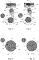
- Figs. 1a-c serve the clarification of the terms and parameters used herein.
- Fig. 1a shows a flexible component 100 whose one end 110 is fixedly clamped.
- the component 100 comprises the length L. If a force F acts on the free end 120 of the component 100, it creates a bending moment and this in turn leads to a bending of the component 100 and hence the displacement of the free end 120 by the distance s.
- the reference point for the measurement of the displacement s is the position of the component 100 in the force-free state which is indicated by the dashed line 130 in Fig. 1a .
- the bending angle of a component 100 for example the angle ⁇ which is given by the angle of intersection of the tangent 140 to the one end 110 of the component 100 with the tangent 145 to the other end 120 of the component 100, may be understood.
- the displacement s and the bending angle ⁇ may be used synonymously.
- the exact relationship between ⁇ and s may be determined from a series of measurements, is necessary.
- the displacement s or the bending angle ⁇ will depend on the acting force F. This dependency is influenced by the bending stiffness of the component 100. An even more detailed definition of the bending stiffness follows below with reference to Fig. 1c .
- Figs. 1a-b merely serve the purpose of clarifying the meaning of the parameters used in this document.
- the one end will not fixedly be clamped to a wall or a fixation device like a vise as shown in Figs. 1a-b during the intended use.
- such an arrangement represents an exemplary possibility for measuring the relevant parameters and properties that may also be used for performing measurements on an embodiment of an inventive supporting element.
- Fig. 1c shows a hypothetical measurement curve resulting from such a measurement performed on a flexible component 100.
- the displacement s of the end 120 of the component 100 is plotted, which results from the force F acting on the component 100.
- This force Fis plotted on the y -axis.
- the x-value also represents a measure for the bending angle ⁇ .
- the bending stiffness may now be a measure for what force is necessary in order to achieve a further bending of the component by a predetermined bending angle, for example by 0.1° or by 1° or the like.
- the force necessary for this can potentially depend on the degree of bending already present in the component.
- the "differential" bending stiffness will therefore preferably be implied. More precisely this means: the bending stiffness preferably designates the slope ⁇ F / ⁇ s of the tangent on the displacement-force-curve of the component 100 in a given state P 1 ( s 1 , F 1 ) and not, for example, the ratio of the absolute values F 1 / s 1 or s 1 / F 1 .
- Figs. 2a-e show a conceivable embodiment of an inventive supporting element 200.
- the supporting element 200 is provided such that it comprises a first bending stiffness for bendings from an initial state without bending up to a threshold angle range and that it comprises a second bending stiffness, which is larger than the first bending stiffness, for bendings beyond the threshold angle range.
- the first bending stiffness and the second bending stiffness each designate a bending stiffness in the longitudinal direction of the supporting element 200, i.e. in the roll-off direction of the foot.
- the supporting element 200 comprises a bending system 205.
- the supporting element 200 further comprises an insole plate 250 on which the bending system 205 is arranged. Further, in this embodiment of an inventive supporting element 200, the bending system 205 is arranged on the insole plate 250 in such a manner that the supporting element 200 is provided to support the front half of the foot, in particular the region of the MTP joints. This can for example be particularly advantageous in sports shoes, in order to guard against injuries of a wearer and to further increase his performance and endurance.
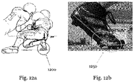
- FIGs. 12a-b snapshots of two different situations/movement patterns which are characteristic for certain sporting activities are depicted.
- Fig. 12a shows a situation of high intensity, as it might occur for example during an American football game.
- the player shown on the right-hand side of the picture supports himself on his right foot in such a manner that a strong hinging and therefore a very high load on the MTP joints results, s. 1200.
- the angle amounts to approximately 90°, caused by the deep "squatting position" of the athlete. This implies a significant potential for injury of the MTP joints and the foot bones and tendons.
- an inventive supporting element it may be ensured by a suitable choice of the threshold angle range, for example in the range from 60° to 90° or 60° to 75° of something similar, that the foot of the player obtains additional support in such situations, such that the acting forces must not be absorbed by the musculo-skeletal system of the athlete only. Moreover, a hinging for example beyond 90° may be prevented or at least impeded. To this end, the second bending stiffness for bendings beyond the threshold angle range may for example be chosen significantly larger than the first bending stiffness. This may significantly reduce the risk of injury.
- Fig. 12b shows the foot of an athlete during running. It is clearly conceivable that the angle in the region of the MTP joints, s. 1250, is significantly smaller than in Fig. 12a . In Fig. 12b , the angle amounts to approximately 40°. The skilled person will understand that it will for example depend on the velocity of the runner how large this hinging angle will maximally be during a movement cycle. For running or walking slowly, the angle may for example not become larger than 20° or 30°. When running faster, the angle can reach for example 40° or more, as shown here.
- the bending stiffness of an embodiment of an inventive supporting element may on the one side be individually adjusted to the conditions and movement patterns predominant in a specific kind of sport in order to support the foot as good as possible and to guard against injuries.
- the first and second bending stiffness and/or the choice of the threshold angle range may be made such that the natural course of movements is impeded as little as possible, or even actively facilitated.
- the insole plate 250 can for example be made from a plastic material. Further, the insole plate 250 typically comprises a bending stiffness that is largely independent from the bending angle of the supporting element 200.
- the insole plate 250 is not necessarily part of every embodiment of an inventive supporting element. Rather, the bending system 205 may also be used in an embodiment of an inventive supporting element or a sole or a shoe without an insole plate 250. The bending system 205 may for example be arranged directly on a midsole layer or an outsole layer or something similar.
- the bending system 205 is provided such that an additional tensile stress is created in the bending system 205 for bendings beyond the threshold angle range and that the bending stiffness is thus increased.
- this additional tensile stress is created in two different ways:
- the bending system 205 comprises a first bending element 210 and a second bending element 220.
- they are provided as two flexible metal sheets.
- the supporting element 200 and in particular the bending elements 210 and 220 comprise one or more different materials like plastic materials, for example polyoxymethylene or polyamide, and/or glass fibers.
- the first bending element 210 and the second bending element 220 are arranged such that they engage with one another for a bending beyond the threshold angle range in order to create the additional tensile stress.
- the way in which this happens is that the first bending elements 210 comprises at least one protrusion 215 which is arranged within a recess 226 of the second bending element 220 and which at least partially abuts in a force-fit manner on an edge of the recess 226 for a bending beyond the threshold angle range.
- This situation, in which the two bending elements "lock up" is particularly clearly depicted in Figs. 2c and 2e .
- the second bending element 220 also comprises at least one such protrusion 225 which is arranged in a recess 216 of the first bending element 210 and which at least partially abuts in a force-fit manner on an edge of the recess 216 in the first bending element 210 for a bending beyond the threshold angle range.
- the protrusion 215 directly transitions into the recess 216 and also the recess 226 directly transitions into the protrusion 225: by the chosen arrangement, the first 210 and the second 220 bending element "interlock" particularly strongly and hence a particularly good transfer of forces between the two bending elements 210 and 220 for bendings beyond the threshold angle range is possible, s. Figs. 2c and 2e .
- the bending system 205 comprises a first securing device 211, 221 and a second securing device 212, 222, wherein the first securing device 211, 221 is arranged such that it prevents a movement of the bending system 205 relative to the first securing device 211, 221, and the second securing device 212, 222 is arranged such that it allows a movement of the bending system 205 relative to the second securing device 212, 222 for a bending up to the threshold angle range and prevents the movement for a bending beyond the threshold angle range and that a tensile stress is thus created in the bending system 205.
- the second securing device 212, 222 is arranged in an opening 218, 228 in the bending system 205 such that it can move essentially freely - i.e. up to small friction forces which are unavoidable due to the construction - within the opening 218, 228 for a bending up to the threshold angle range, and that a further movement is prevented by an edge of the opening 218, 228 for bendings beyond the threshold angle range.
- This situation in which a further movement is prevented and thus the tensile stress is created within the bending system 205, is particularly clearly depicted in Figs. 2c and 2e .
- openings 218, 228 are provided as an elongated hole, as indicated here.
- oval openings or straight or curved grooves or something similar are also conceivable.
- a first securing device 211, 221 and/or second securing device 212, 222 in particular one or more screws and/or rivets may be considered, which may for example be made of plastics and/or metal.
- different securing devices for example made from plastics are also conceivable.
- the first bending element 210 is arranged in the lateral mid- to forefoot region and the second bending element 220 in the medial mid- to forefoot region.
- the first securing device 211 comprises a double rivet at the side of the first bending element 210 that faces the midfoot.
- the second securing device 212 comprises a rivet in the middle of the first bending element 210 as well as a double rivet at the side of the first bending element 210 that faces the tip of the foot.
- the first securing device 221 comprises a double rivet at the side of the second bending element 220 that faces the tip of the foot.
- the second securing device 222 comprises a rivet in the middle of the second bending element 220 as well as a double rivet at the side of the second bending element 220 that faces the midfoot.
- first securing devices 211, 221 and/or the second securing devices 212, 222 may be varied in their arrangement and number such that the desired properties of the bending system 205 and the supporting element 200 may be achieved.
- FIG. 9 A possible variation is for example shown in Fig. 9 .
- the embodiment of a bending system 905 shown there is similar to the embodiment of the bending system 205. In this respect, reference is made to the explanations regarding the bending system 205.
- the bending system 905 in particular comprises a first bending element 910 and a second bending element 920, which each comprise protrusions 915, 925 and corresponding recesses 916, 926.
- the bending system 905 differs mainly in the arrangement of the first 911, 921 and second 912, 922 securing devices.
- the first securing device 911 comprises a double rivet at the side of the first bending element 910 facing the tip of the foot.
- the second securing device 912 comprises a rivet in the middle of the first bending element 910 as well as a double rivet at the side of the first bending element 910 facing the midfoot.
- the first securing device 921 comprises double rivet at the side of the second bending element 920 facing the midfoot.
- the second securing device 922 comprises a rivet in the middle of the second bending element 920 as well as a double rivet at the side of the second bending element 920 facing the tip of the foot.
- a bending system (not shown) based on this principle only comprises, for example, a first bending element 210 with a first securing device 211 and a second securing device 212 as described above.
- the bending system can for example comprise a single bending element, for example in the form of a metal- or plastic sheet.
- the bending system can further comprise a first securing device with which the bending element is fixedly connected with a sole, for example riveted or screwed.
- the bending system can comprise a second securing device, for example a rivet or screw arranged within an elongated hole or some other opening in the bending element.
- the second securing device allows the bending system to move essentially freely - i.e. up to small friction forces that are unavoidable due to the construction - within the elongated hole or the opening for a bending up to the threshold angle range.
- the first securing device may be arranged in the forefoot region of the sole and the second securing device in the midfoot region, or vice versa.
- the embodiment of an inventive bending system 1005 shown in Fig. 10 comprises a first bending element 1010 and a second bending element 1020, which each comprise at least one protrusion 1015, 1025, which lock up (s. right half of Fig. 10 ) with at least one corresponding recess 1016, 1026, respectively, for bendings beyond the threshold angle range in order to create the additional tensile stress and therefore the increased bending stiffness in the bending system 1005.
- the first and second bending element 1010, 1020 are for example fixedly connected with a sole, sole plate or something similar at an appropriate position (not shown). For more details on this, reference is made to the other embodiments described herein, in particular the explanations with regard to the supporting element 200.
- the embodiment of an inventive bending system 1105 shown in Fig. 11 also comprises a first bending element 1110 and a second bending element 1120.
- the first bending element 1110 and the second bending element 1120 are for example also fixedly connected with a sole, sole plate or something similar by means of corresponding first securing device (not shown), s. the discussion with respect to Fig. 10 .
- the first bending element 1110 and the second bending element 1120 each comprise at least one second securing device 1112, 1122, arranged in a corresponding elongated hole 1118, 1128 in the first or second bending element 1110, 1120, respectively, in such a manner that they allow the bending system 1105 to move essentially freely - i.e.
- the bending systems 905, 1005 or 1105 may for example be substituted for the bending systems 205 or 405 in the supporting elements 200 or 400 (regarding the supporting element 400, s. below).
- Figs. 2b-e , 9 , 10 and 11 mainly serve the purpose of illustrating the two above-mentioned mechanisms and that they do not necessarily show the actual proportions in every detail.
- the bending systems 205, 905, 1005 and 1105 described here are not coupled to the use of an insole plate 250.
- the first securing devices 211, 221 may also be replaced by the first bending element 210 and/or the second bending element 220 being firmly bonded at the respective position with, for example, a midsole and/or an outsole, or being embedded in their material.
- the position of the threshold angle range depends primarily on how much "clearance” there is in the neutral, force-free state (i.e. how large the distance is):
- the respective distances are chosen such that the two mechanisms lock up in different threshold angle ranges and therefore lead to a step-wise increase of the bending stiffness of the supporting element 200.
- the distance mentioned under b) above may be chosen larger, for example twice as large, as the distance mentioned under a) (or vice versa, s. below).
- the protrusions 215, 225 and recesses 216, 226 will initially lock up for bendings beyond a first threshold angle range, while a movement of the bending system 205 relative to the second securing devices 212, 222 is still possible, as they do not yet "abut" on the edge of the openings 218, 228.
- the securing devices 211, 212, 221 and 222 may also serve the purpose of preventing the bending elements 210, 220 from sliding on top of each other and potentially getting jammed.
- the threshold angle range discussed so far corresponds to a first threshold angle range and a supporting element 200 is obtained that is provided such that it comprises a first bending stiffness for bendings from the initial state without bending to the first threshold angle range and comprises a second bending stiffness for bendings beyond the first threshold angle range, wherein the second bending stiffness is larger than the first bending stiffness.
- the supporting element is further provided such that for bendings beyond the second threshold angle range it comprises a third bending stiffness, which is larger than the second bending stiffness, wherein the second threshold angle range, measured relative to the initial state, extends across larger angles than the first threshold angle range.
- the proportions are reversed, i.e. the distance mentioned under a) between the engaging protrusions 215, 225 and recesses 216, 226 of the first bending element 210 and second bending element 220 is larger than the distance mentioned under b) between the second securing devices 212, 222 and the edges of the corresponding openings 218, 228 in the bending system 205.
- the distance mentioned under a) may for example be approximately 1.2 mm and the distance mentioned under b) for example approximately 1 mm.
- the securing devices 212, 222 lock up with the edges of the openings 218, 228 before the protrusions 215, 225 lock up with the recesses 216, 226.
- This provides the advantage that a sliding on top of each other and a potential jamming of the bending elements 210 and 220 may be prevented particularly well. This, in turn, may further increase the durability of the bending system 205.
- the ratio of the first bending stiffness to the second bending stiffness in particular depends on how large the additional tensile stress is which is created in the bending system 205 for bendings beyond the threshold angle range. It depends, among other things, on the material of the bending system 205, its length, thickness, and so forth. Possible are values for the ratio of the second to the first bending stiffness lie between 1.1 : 1 and 4 : 1, in particular between 1.2 : 1 and 3 : 1, particularly between 2 : 1 and 2.4 : 1. These values have turned out suitable to obtain the desired roll-off and supporting properties discussed in the beginning.
- Figs. 3a-b show a further embodiment of an inventive sole 300 for a soccer shoe.
- the sole 300 comprises a supporting element, which, in the case of Figs. 3a-b , is the above-described supporting element 200 that comprises an insole plate 250 and a bending system 205.
- the sole 300 further comprises an outsole 340.
- the outsole comprises a number of cleat elements 342.
- the cleat elements may potentially be provided as an integral piece with the remainder of the outsole 340. This leads to particular high stability of the outsole 340.
- the outsole 340 potentially comprises a transparent window 345.
- This window allows to have a look at the "interior workings" of the sole and the mechanics of the supporting element 200 from the outside.
- the window need not, however, be necessarily transparent, rather it can also be semi-transparent and/or comprise a declaration foil, and so forth.
- the window is not a mandatory part of embodiments of inventive soles. It is also possible that an embodiment of an inventive sole only comprises a cavity, for example, which provides room for the inner workings of the sole, in particular for an embodiment of an inventive supporting element or bending system.
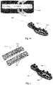
- Figs. 4a-d show a further conceivable embodiment of an inventive supporting element 400.
- the explanations made with regard to the supporting element 200 also apply analogously to the supporting element 400 shown in Figs. 4a-d .
- Differences between the supporting elements 200 and 400 first and foremost lie in the shape and arrangement of the first 210, 410 and second 220, 420 bending elements, in the shape of the protrusions 215 & 225, 415 & 425 and recesses 216 & 226, 416 & 426 as well as in the arrangement of the first 211 & 221, 411 & 421 and second 212 & 222, 412 & 422 securing devices.
- Figs. 4a-b the supporting element 400 is shown in the neutral, force-free state, whereas Figs. 4c-d show the supporting element 400 under a bending beyond the threshold angle range.
- Fig. 4a shows the supporting element 400 in its entirety.
- the supporting element 400 comprises an insole plate 450 and a bending system 405.
- the supporting element 400 is provided such that it supports in particular the front half of the foot in the above-described inventive manner.
- the insole plate 450 comprises a cavity 490 in the embodiment shown here. This cavity can for example serve the purpose of receiving an electronic component or something similar. It shall be mentioned here, however, that such a cavity 490 is merely an optional feature and is not a mandatory part of embodiments of inventive supporting elements or soles.
- Fig. 4b shows an enlarged view of the front half of the supporting element 400 including the bending system 405.
- the bending system 405 comprise a first bending element 410 and a second bending element 420.
- the two bending elements 410 and 420 are manufactured from spring steel sheets, for example with a thickness from 0.3 mm to 0.7 mm, for example 0.5 mm, in the embodiment shown here. It is noted that the bending elements 410 and/or 420 may, however, also comprise different materials or be made from different materials, for example plastic materials.
- the first bending element 410 further comprises protrusions 415 which are each arranged in a recess 426 of the second bending element 420 and which at least partially abut in a force-fit manner on an edge of the respective recess 426 for a bending beyond the threshold angle range, as shown in Figs. 4c and 4d .
- the second bending element 420 comprises protrusions 425 which are arranged in recesses 416 of the first bending element 410 and which at least partially abut in a force-fit manner on an edge of the respective recess 416 for a bending beyond the threshold angle range. This leads to an additional tensile stress in the bending system 405 for a bending beyond the threshold angle range, which increases the bending stiffness of the bending system 405 and hence the supporting element 400 (s. Fig. 4e ).
- each of the two bending elements 410 and 420 comprises at least one first securing device 411, 421 and one second securing device 412, 422.
- the first securing device 411, 421 and the second securing device 412, 422 are each comprised of one or several rivets.
- the first securing device 411, 421 is arranged such that it prevents a movement of the first/second bending element 410/420 relative to the first securing device 411/421.
- the first/second bending element 410/420 is fixedly riveted to the insole plate 450 by the rivets 411/421.
- the second securing device 412/422 is comprised of rivets which are fixedly connected with the insole plate 450 and which are, however, arranged in elongated holes in the first/second bending element 410/420 (which are not visible in Figs. 4a-d since they are hidden by the heads of the rivets) in such a manner that they may move essentially freely within the elongated holes for bendings up to a threshold angle range.
- an edge of the elongated holes prevents a further movement and hence creates an additional tensile stress in the bending elements 410 and 420 and therefore in the bending system 405.
- the clearance i.e. the distance between the protrusions 415, 425 and the respective edge of the corresponding recesses 416, 426, amounts to approximately 1.2 mm in the embodiment shown here.
- the clearance of the rivets 412 and 422 in the elongated holes is chosen approximately the same size.
- the clearance of the rivets 412, 422 in the elongated holes is for example approximately 1 mm. As shown in Fig. 4e , this has the effect that the threshold angle range - measured relative to the initial state, s. the explanations with regard to Fig. 1b - lies in the range around displacements of approximately 7 mm in the present embodiment, which corresponds to a bending angle of approximately 20° for the supporting element 400 of shoe size UK 8.5.
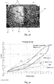
- Figs. 4e-f show different displacement-force-curves 471, 472, 473, 474, which were measured with a measuring method like the method described in Figs. 1a-c .
- the measurement curves 471, 472 and 473 show displacement-force-curves for supporting elements from the prior art, whereas the displacement-force-curve 474 corresponds to the inventive supporting element 400. Supporting elements for soles of shoes with shoe size UK 8.5 where used in the measurements.
- the first bending stiffness for bendings up to the threshold angle range is smaller than for bendings beyond the threshold angle range.
- the threshold angle range lies in the range between approximately 5 mm to 9 mm. That means that the supporting elements known from the prior art become softer starting from the neutral, force-free initial state.
- the first bending stiffness of the supporting element 400 is approximately constant for bendings up to the threshold angle range.
- the second bending stiffness for bendings beyond the threshold angle range at least up to a saturation value for high bending angles.
- the exact shape of the displacement-force-curve of an embodiment of an inventive supporting element depends on the chosen specific design in a given case. As already mentioned numerous times, it is important that the supporting element comprises a first bending stiffness for bendings up to the threshold angle range and a second bending stiffness for bendings beyond the threshold angle range, wherein the second bending stiffness is larger than the first bending stiffness.
- the ratio of the second bending stiffness to the first bending stiffness is approximately 78 N mm -1 / 35 N mm -1 ⁇ 2.23.
- the measurement curves 471, 472, 473 and 474 show the characteristic shape of hysteresis-curves.
- Figs. 5 , 6a-c , 7 and 8 show further possible embodiments of inventive supporting elements, as well as embodiments of shoe soles and shoes with such supporting elements.
- inventive supporting elements as well as embodiments of shoe soles and shoes with such supporting elements.
- the explanations put forth in the context of the embodiments already discussed in general also apply - if applicable - to all embodiments discussed in the following or being otherwise conceivable. This is in particular true for the location of the threshold angle range, the ratio of the first and the second bending stiffness, conceivable materials for being used, and so forth.
- Fig. 5 shows a further embodiment of an inventive supporting element 500.
- the supporting element 500 comprises a bending system 500 which is provided such that for a bending beyond a threshold angle range an additional tensile stress is created in the bending system 500 and in this way the bending stiffness is increased.
- the bending system 500 this is achieved by the bending system 500 comprising a first bending element 510 and a second bending element 520 which are arranged in such a manner that they engage with each other for a bending beyond the threshold angle range in order to create the additional tensile stress.
- the first bending element 510 comprises at least one protrusion 515 which is arranged in a recess 525 of the second bending element 520 and which abuts in a force-fit manner on an edge of the recess 525 for a bending beyond the threshold angle range.
- the bending system 500 shown in Fig. 5 comprises four such protrusions 515 and four corresponding recesses 525, wherein the protrusions 515 are provided with a quadratic cross-section and the recesses 525 with a rectangular cross-section.
- the protrusions 515 are provided with a quadratic cross-section and the recesses 525 with a rectangular cross-section.
- a different number of protrusions 515 and/or recesses 525 is conceivable.
- a different cross-sectional shape may be chosen.
- the protrusions 515 could for example be provided with a circular cross-section and the recesses 525 correspondingly as an elongated holes. It is in particular conceivable that the protrusions 515 are provided as pins, for example with a circular or oval cross-section.
- This may for example serve the purpose of simplifying the manufacture compared to the bending system 500 shown in Fig. 5 .
- the transfer of forces between the protrusions 515 and the edges of the recesses 525 for bendings beyond the threshold angle range may potentially be better.
- the first bending element 510 and/or the second bending element 520 may be provided as flexible metal sheets. It is, however, also conceivable, that the first bending element 510 and/or the second bending element 520 comprise one or more of the following materials: plastics, for example polyoxymethylene and/or polyamide, glass fibers.
- a shoe 550 is further shown in Fig. 5 , which comprises a sole 540 with a supporting element 500.
- the supporting element 500 is arranged such that it supports the foot in the region of the front half of the foot, in particular in the region of the MTP joints.
- the first bending element 510 is for example connected with a midsole layer (not shown) of the sole 540, for example by means of screws 513 and/or rivets (not shown) at the two ends 512 of the first bending element 510 provided for this purpose, whereas the end of the second bending element 520 facing the tip of the foot (the front end) is connected to an outsole layer of the sole 540.
- the front end of the second bending element 520 may for example be embedded in the material of the outsole and/or be fixated to the outsole by additional fixation devices 542.
- fixation devices 542 may for example be manufactured as a single integral piece with the outsole in such a manner that the second bending element 520 snaps into the fixation devices 542 under pressure and is hence fixated, as shown in Fig. 5 .
- the second bending element 520 connected to the outsole in this manner will slide relative to the first bending element 510 fixedly connected with the midsole. For bendings beyond the threshold angle range, however, a further sliding is prevented by the engaging protrusions 515 and recesses 525 and an additional tensile stress is created within the sole 540.
- Figs. 6a-c show further embodiments of inventive supporting element 600a, 600b and 600c.
- the supporting elements 600a, 600b, 600c each comprise a bending system 600a, 600b, 600c that is provided in such a manner that for a bending beyond a threshold angle range an additional tensile stress is created in the bending system 600a, 600b, 600c and thus the bending stiffness is increased.
- the bending systems 600a, 600b, 600c each comprises a rope element 625a, 625b, 625c, wherein for bendings up to a threshold angle range the rope element 625a, 625b, 625c is subject to a first tensile stress and for bendings beyond the threshold angle range is subject to a second tensile stress, which is larger than the first tensile stress.
- the first tensile stress is equal to zero, i.e. for bendings up to the threshold angle range there is a certain degree of "slack rope" in the rope element 625a, 625b, 625c.
- the rope element 625a, 625b, 625c can for example comprise two kinds of fiber elements (not shown), of which the first kind is already subject to a tensile stress for bendings up to the threshold angle range while the second kind is initially essentially free of tension and only become subject to a tensile stress for bendings beyond the threshold angle range.
- the supporting element 600a shown in Fig. 6a comprises a first bending element 610a as well as a second bending element 620a.
- the rope element 625a is further connected to two opposing ends of the second bending element 620a and diagonally wound around it in such a manner that for bendings up to the threshold angle range there is a certain degree of "slack rope" in the rope element 625a, while for bendings beyond the threshold angle range the rope element 625a is stretched and hence an additional tensile stress is created within the rope element 625a.
- the first bending element 610a may for example be fixedly arranged at the second bending element 620a, for example by means of screws 622a as shown in Fig. 6a and/or by means of rivets.
- first bending element 610a and the second bending element 620a are connected to each other in such a manner that for bendings up to the threshold angle range they may initially move with respect to each other and only for bendings beyond the threshold angle range lock up, as already described herein.
- the screws 622a may for example be arranged within elongated holes of the second bending element 620a.
- the creation of the additional tensile stress in the rope element 625a may then set in in the same threshold angle range in which the screws 622a lock up with the second bending element 620a, or in a different threshold angle range, for example at larger bending angles.
- Fig. 6a further shows a shoe 650a with a sole 640a with a supporting element 600a which is connected with the sole 640a by means of screws 613a and/or rivets (not shown) at the ends 612a provided for this.
- additional fixation devices 642a can further fixate the supporting element 600a at the sole 640a.
- the supporting element 600b shown in Fig. 6b only comprises one bending element 610b.
- the bending element 610b comprises a rope element 625b, which is guided in a zig-zag manner around a plurality of protrusions 615b.
- the rope element 625b, the shoe 650b and the arrangement of the supporting element 600b at the sole 640b of the shoe 650b the above statements apply.
- the supporting element 600c shown in Fig. 6c differs from the supporting element 600b shown in Fig. 6b only by the arrangement of the rope element 625c, which in the case of the supporting element 600c shown in Fig. 6c partially extends along a top side and partially along a bottom side of the supporting element 600c.
- the shoe 650c with a sole 640c with a supporting element 600c shown here there are no significant differences to the shoes 650a or 650b, too.
- Fig. 7 shows a further inventive embodiment of a supporting element 700 as well as a shoe 750 with a sole 740 with such a supporting element 700.
- the supporting element 700 is provided such that it comprises a first bending stiffness for bendings from an initial state without bending up to a threshold angle range and a second bending stiffness for bendings beyond the threshold angle range, which is larger than the first, too.
- the ratio of the first and the second bending stiffness, and so forth reference is again explicitly made to the explanations further above which also apply to the supporting element 700.
- the supporting element 700 comprises a bending system 700.
- the bending system 700 is now, however, provided in such a manner that for a bending beyond the threshold angle range and additional compressive stress is created in the bending system 700 and the bending stiffness is thus increased.
- the bending system 700 comprises a first pressure element 710 and a second pressure element 720. They are arranged in such a manner that for a bending beyond the threshold angle range, the first pressure element 710 and the second pressure element 720 are pressed onto each other in order to create an additional compressive stress which counteracts a further bending and therefore increases the bending stiffness of the bending system 700.
- the first pressure element 710 and the second pressure element 720 are for example provided such that for a bending up to the threshold angle range no additional compressive stress is created between the pressure elements 710 and 720.
- a suitable clearance may for example be present between the first pressure element 710 and the second pressure element 720 in the force-free initial state without bending.
- the skilled person will further realize that by a suitable choice of the material of the first and/or second pressure element 710, 720, the additionally created compressive stress and hence the increase in the bending stiffness can be influenced.
- the use of rubber for the pressure elements 710, 720 would lead to rather small additional compressive stresses and a rather small increase in the bending stiffness for bendings beyond the threshold angle range, compared to, for example, the use of spring steel.
- such a supporting element as a single integral piece wherein recesses with a conical shape, which can be arranged on the side of the sole facing towards the interior of the shoe, extend between the first and second pressure elements.
- recesses with a conical shape which can be arranged on the side of the sole facing towards the interior of the shoe, extend between the first and second pressure elements.
- the conical recesses may disappear due to the bending of the supporting element such that the first and second pressure elements are pressed onto each other in order to create the additional compressive stress.
- the design of the conical recesses, in particular their angle influences the threshold angle range.
- Fig. 8 shows a further conceivable variation 800 of the shoe 750 shown in Fig. 7 .
- a supporting element for example the supporting element 700
- the pressure elements 710, 720 will potentially be arranged on the side of the shoe upper 840 facing away from the interior of the shoe in this case.
- the same considerations put forth with regard to the embodiments 700 and 750 shown in Fig. 7 apply.
- Sole according to example 1.8 wherein the first bending element and the second bending element are arranged next to each other, in particular on a bottom side of a midsole plate or an insole plate.
- Shoe in particular soccer shoe, comprising a sole according to any one of the preceding examples 1.1 - 1.14.
Landscapes
- Health & Medical Sciences (AREA)
- General Health & Medical Sciences (AREA)
- Physical Education & Sports Medicine (AREA)
- Footwear And Its Accessory, Manufacturing Method And Apparatuses (AREA)
Abstract
Description
- The present invention relates to a supporting element for shoes, in particular for soccer shoes or American football shoes, as well as a sole and a shoe with a supporting element.
- Nowadays, shoes are provided with a plethora of different properties and are often manufactured from different shoe parts. Depending on the specific kind of shoe and the parts used for the manufacture, these properties may be pronounced to different degrees.
- Shoe soles, for example, primarily comprise a protective function. Furthermore, the outsole usually protects the midsole of a shoe by an increased abrasion resistance from excessive wear. A shoe sole may also have a cushioning effect, for example to cushion or absorb the forces occurring during contact of the shoe with the ground. Furthermore, a shoe sole can protect the foot from dirt or spray water.
- A further function of a shoe sole can be to increase the traction or grip of a shoe on the respective ground in order to facilitate faster movements and to minimize the risk of the wearer falling.
- In particular for ball sports, like e.g. soccer, American football, baseball or basketball, but also for running sports, there is often a change between movements in different intensity- and strain ranges during the course of the game or run. Implied are on the one side movements with a lower intensity, e.g. running, trotting or jogging slowly, etc., for which the athlete does not have to expend overly large forces. However, such movements are typically performed over a longer period of time. On the other hand, however, phases of high movement intensity are also often part of a game, e.g. a soccer game, an American football game, a baseball game or a basketball game, or part of a run, like e.g. a cross-country run or a mountain run, for example during a sprint, while jumping, during sudden changes of direction, during mountain running, and so forth. Typically, the different intensity ranges also imply characteristic movement patterns, which may sometimes differ from each other significantly.
-
US 6,954,998 B1 is directed to an article of footwear including a sole with a chassis constructed to provide, in a pre-selected manner, comfort, flexibility, support, and power transfer by varying the configuration, thickness, and/or material of the chassis in various areas of the chassis, thereby providing for varying degrees of stiffness in the footwear. -
WO 2009/106077 A1 is directed to a midsole having an arch support, in particular a midsole for running shoes. -
WO 2010/121709 A1 is directed to a shoe, particularly a sports shoe, having a sole, wherein the sole has at least one spring element increasing the flexural rigidity of the sole about an axis aligned horizontally and perpendicular to a longitudinal axis of the sole. -
WO 2004/021819 A1 is directed to a shoe or footwear item comprising a sole consisting of an outer face which is intended to come into contact with the ground and an inner face which is intended to come into contact with the foot of the user. The sole includes a dynamic support element which comprises at least two elastically-deformable elements and which is used to store and release energy when said sole is subjected to lateral stresses. -
US 7,832,117 B2 is directed to a full length composite plate to be used as part of an outsole assembly in an article of footwear. The full length composite plate comprises a composite material that has a certain percent elongation. The full length composite plate can include a heel cup for heel stability and improved traction. The full length composite plate also can include two angled portions along an arch region that provide arch support, as well as two flattened edges along the arch region to minimize or eliminate buckling. The forefoot region can be relatively flatter than the arch and heel regions, and notches are preferably included along a portion of the forefoot to increase flexibility. -
DE 19 73 891 U discloses a sole for a sports shoe, in particular a soccer shoe, which is easier to bend in the direction towards the bottom of the foot than in the opposite direction in the region of the joints. -
US 2014/0000131 A1 concerns a flexible shank for an article of footwear that provides support to the bottom of a user's foot along with flexibility in one or more selected directions. -
US 8,418,379 B2 relates to a shoe sole with a reinforcement structure including a so-called "shank" (a reinforcement member). -
US 1,466,384 A discloses an arch support for shoes composed of a plurality of parts hingedly connected together, said parts being anchored and rigidly secured to a part of the shoe on each side of said hinge connection. -
US 2012/0096746 A1 discloses a sole for a footwear comprising a body having a length, a body portion of the body capable of expansion and contraction; and a drive generator provided in the body for generating drive to drive a device in the body; wherein the drive generator comprises an elongate drive member arranged to slide relative to the body portion in a direction along the length thereof upon expansion and contraction of the body portion for driving said device, as the sole bends and unbends during use. -
US 2010/0154258 A1 discloses a sole for a shoe, in particular a sports shoe, which includes a unidirectional bending element. The unidirectional bending element enables a dorsal bending of the sole (bending of the sole in the direction upward and away from the ground) and blocks a plantar bending of the sole (bending of the sole in the direction downward and towards the ground). The unidirectional bending element may be arranged at a first layer of the sole and may vertically project from the first layer. - Further prior art is known from
US 4,779,361 A ,WO 2013/039702 A2 ,US 8,418,379 B2 andUS 1,466,384 A . - Given this background, a disadvantage of the shoes known from the prior art is that these shoes are typically intended for a single field of application and are adapted to the respective characteristic movement pattern.
- Starting from the prior art, it is therefore a problem of the present invention to provide a supporting element, a sole and a shoe, which can dynamically adapt to the changing requirements which result from the change between movements in different intensity ranges.
- According to a first aspect of the present invention, this problem is at least partially solved by a supporting element for a shoe, in particular a soccer shoe or an American football shoe, wherein the supporting element is provided such that it comprises a first bending stiffness for bendings from an initial state without bending up to a threshold angle range and comprises a second bending stiffness for bendings beyond the threshold angle range, wherein the second bending stiffness is larger than the first bending stiffness.
- For movements of lower intensity, like for example running, trotting or jogging slowly, it is characteristic that in the region of the metatarsophalangeal joints (MTP joints), also called toe base joints, only a slight hinging occurs. It is important for such movements that roll-off of the foot may proceed as naturally as possible. It is further of advantage if as little energy as possible is absorbed by the sole and hence withdrawn from the athlete. In general, one can say that in these intensity ranges a comfortable and energy-saving way of running is of primary importance, and the natural movement patterns shall preferably be maintained. This is ensured by an embodiment of the inventive supporting element comprising a first, lower bending stiffness for bendings from an initial state without bending up to a threshold angle range such that it only insignificantly influences the natural flow of movements.
- Meanwhile, for phases of high movement intensity it is characteristic that the athlete has to transfer very high forces, in particular push-off forces, to the ground in a short time. The better the transfer of forces from the athlete to the ground is, the faster he can run or change direction, the higher he can jump, and so forth. It is characteristic for such movements that the foot is strongly hinged in the MTP joints and the transfer of forces predominantly occurs via the forefoot. This hinging is further intensified, in particular during fast running or sprinting, by the posture of the athlete being tilted in the forward direction. In order to ensure as large a transfer of forces as possible, the foot must not yield to the forces acting in such a situation, since otherwise the forces will "come to nothing".
- This means that the muscles of the athlete, in particular the foot muscles and the calf muscles, have to ensure that the above-mentioned angle in the region of the MTP joints is maintained and at the same time ensure as strong a push-off of the foot from the ground as possible. This results in a significant load on the respective muscle groups. It is therefore desirable for such movement phases that the sole provides for improved support, in order to relief the supporting muscles of the athlete and to improve traction between the foot and the ground. This is also facilitated by an embodiment of the inventive supporting element as it comprises a second bending stiffness, which is larger than the first bending stiffness, for bendings beyond the threshold angle range and hence supports the foot during push-off as just explained.
- A number of technical realizations and embodiments of the inventive supporting element as just described are conceivable, of which several will be described in the following. Reference is, however, already at this point made to the fact that the inventive supporting element cannot be restricted to the embodiments explicitly described herein.
- It is for example conceivable that the threshold angle range extends from 10° to 30°, wherein the bending angle is measured relative to an initial state without bending. It is in particular conceivable that the threshold angle range extends from 15° to 25° and particularly from 18° to 22°.
- It was found that the transition between movements of lower intensity and higher intensity in the sense discussed above typically occurs for flex angles in the foot region, in particular in the region of the MTP joints, in these ranges of angles, such that it is advantageous if the supporting element transitions in these ranges of angles from its "soft phase", in which it comprises the first bending stiffness, to its "stiff phase", in which it comprises the second, larger bending stiffness.
- Conceivable is further a ratio of the second bending stiffness to the first bending stiffness in the range from 1.1 : 1 to 4 : 1, in particular in the range from 1.2 : 1 to 3 : 1 and particularly from 2 : 1 to 2.4 : 1.
- Such a ratio of the bending stiffnesses represents an optimal compromise between providing for the above discussed, desirable roll-off and supporting function of a shoe with such a supporting element on the one side, and the general functionality and the wearing comfort of such a shoe on the other side.
- It is further conceivable that in the threshold angle range both a continuous change of the bending stiffness of the supporting element as well as a stepwise change occurs. More detailed explanations to this point will follow below in the context of the discussion of inventive embodiments.
- By a suitable choice of the threshold angle range and the ratio of the first bending stiffness to the second bending stiffness, the behavior of the supporting element may further be individually adapted to the respective requirements. Such different requirements will be explained further below in the detailed description in relation to
Figs. 12a-b in more detail. - In this context, the first bending stiffness and the second bending stiffness for example each designate a bending stiffness of the supporting element along a roll-off direction of the foot. It is furthermore conceivable that the supporting element is provided to support the front half of the foot, in particular the region of the MTP joints.
- As already explained, the hinging of the MTP joints represents a decisive criterion for the transition between the different intensity ranges of the movements of an athlete, such that a supporting element can react to a change in the hinging by adjusting its bending stiffness along a roll-off direction of the foot and support the foot at high intensities in this region.
- It is, however, also conceivable that the supporting element has a supporting effect in other regions, for example in the midfoot region or the heel region, or that the bending stiffness designates the bending stiffness with respect to another preferred direction, for example the medial-lateral direction.
- It is conceivable that the supporting element comprises a bending system that is provided such that for a bending of the bending system beyond the threshold angle range an additional tensile stress is created within the bending system and that the bending stiffness is thus increased.
- A bending moment acting on the bending system for bendings beyond the threshold angle range can for example be translated into an additional tensile stress which acts on the bending system. The additional tensile stress in the bending system creates a restoring force, which counteracts a further bending of the bending system and thus increases the bending stiffness of the bending system for bendings beyond the threshold angle range. By the choice of the material for the bending system, the additional tensile stress or the increase in bending stiffness thus achieved may be influenced.
- In this regard, it is further conceivable that the energy exerted by creating the tensile stress during bending of the bending system is at least partially returned again as soon as the bending angle decreases again. This can further facilitate the movement of the athlete.
- It is further possible that the bending system comprises a first bending element and second bending element which are arranged such that they engage with each other for bendings beyond the threshold angle range in order to create the additional tensile stress.
- For bendings up to the threshold angle range, the first bending element and the second element can slide with respect to each other or otherwise move freely or mostly unhampered. For bendings beyond the threshold angle range, on the other hand, the first and the second bending element engage with each other. This prevents or hampers further movement, resulting in a tensile stress in the first and/or the second bending element. This tensile stress can in turn increase the bending stiffness of the bending system as described above.
- The first bending element may comprise at least one protrusion which is arranged in a recess of the second bending element and abuts in a force-fit manner on an edge of the recess for a bending beyond the threshold angle range. Herein, the protrusion may in particular move freely within the recess for bendings up to the threshold angle range.
- This represents an embodiment of such an inventive bending system with a simple and simultaneously robust construction. In addition, such an embodiment may allow achieving a clearly noticeable difference between the first bending stiffness and the second bending stiffness.
- Herein, it is in particular possible, that the first and the second bending element are provided as two flexible metal sheets. Conceivable are for example metal sheets made from spring steel. The first and the second bending element can also be manufactured from a plastic material or they may at least comprise a plastic material. Compared to a metal, a plastic may in particular be lightweight and very inexpensive in the manufacture, and plastics may even be more stable with respect to bendings as a metal.
- Metal sheets have the advantage that they can be manufactured very thin and, if desired, flexible, such that the bending stiffness for bendings up to the threshold angle range can be maintained low. At the same time, metal sheets comprise a very high stability and tensile strength.
- On the one hand, it is conceivable that the first bending element and the second bending element are arranged next to each other, for example on a bottom side of a mid- or insole plate. On the other side, however, it is also conceivable that the first bending element and the second bending element are arranged on top of each other.
- It is conceivable that the bending system comprises a first securing device and a second securing device, wherein the first securing device is arranged such that it prevents a movement of the bending system relative to the first securing device, and wherein the second securing device is arranged such that it allows a movement of the bending system relative to the second securing device for a bending up to the threshold angle range and prevents the movement for a bending beyond the threshold angle range and thus creates a tensile stress in the bending system.
- This represents a further possibility to increase the bending stiffness of the bending system for bendings beyond the threshold angle range. It is in particular conceivable that this design possibility is used in combination with the first bending element and the second bending element described above.
- The second securing device may be arranged within an opening in the bending system such that it can move essentially freely within the opening for a bending up to the threshold angle range and that a further movement is prevented by an edge of the opening for bendings beyond the threshold angle range. It is for example conceivable that the opening in the bending system is provided as an elongated hole.
- Within this document, and essentially free movement designates a movement where only small friction forces occur which are unavoidable due to the construction.
- This represents a possibility for providing an embodiment of an inventive supporting element with a particularly simple construction. The first and the second securing device may for example be rivets or screws which connect the bending system with an insole plate, for example made of plastic, metal, a foam material, or something similar.
- It is also conceivable that the bending system comprises a rope element wherein the rope element is subject to a first tensile stress for bendings up to the threshold angle range and wherein the rope element is subject to a second tensile stress, which is larger than the first tensile stress, for bendings beyond the threshold angle range.
- This, too, represents a possibility for providing an embodiment of an inventive supporting element with a simple construction which in addition may be provided very space-saving. Further, by means of the tensile strength of the rope, the bending stiffness of the supporting element may be influenced in a simple manner.
- Herein, the first tensile stress is for example zero. That is, the rope element is initially arranged at the bending system without any stress. The rope element is subject to a tensile stress only for bendings of the supporting element or the bending system, respectively, beyond the threshold angle range, leading to an increase of the bending stiffness of the bending system. Hence, the bending stiffness of the bending system for bendings beyond the threshold angle range may be influenced by a suitable choice of the material parameters of the rope element directly and in a particularly easy manner.
- In a further embodiment, the supporting element comprises a bending system that is provided such that for a bending beyond the threshold angle range an additional compressive stress is created within the bending system and the bending stiffness is thus increased.
- Here, then, a compressive stress counteracts a further bending of the bending system as a restoring force for bendings beyond the threshold angle range, leading to an increase of the bending stiffness of the bending system for such bendings.
- In this context, is also conceivable that the energy exerted by creating the compressive stress when bending the bending system is at least partially returned as soon as the bending angle decreases again. This further facilitates movements in an advantageous manner.
- It is conceivable that the bending system comprises a first pressure element and a second pressure element that are arranged such that they are pressed onto each other for bendings beyond the threshold angle range in order to create the additional compressive stress.
- Such a supporting element may for example be employed in a shoe sole. It is, however, also conceivable that such a supporting element is arranged on a shoe upper, for example in the region of the instep or the tongue, or something similar.
- The threshold angle range mentioned so far may for example be a first threshold angle range and the supporting element may further be provided such that it comprises a third bending stiffness, which is larger than the second bending stiffness, for bendings beyond a second threshold angle range and wherein the second threshold angle range, measured relative to the initial state, extends across larger angles as the first threshold angle range.
- This allows an even more detailed and selective adjustment of the bending stiffness of the supporting element to the different loads, movement phases and movement patterns of the wearer in several "stiffness stages".
- It is possible that the supporting element comprises one or more of the following materials: metals, plastics, in particular spring steel, polyoxymethylene, polyamide, glass fibers.
- As already mentioned, spring steel has the advantage that it may be provided very thin and, if desired, also flexible, while still comprising a high stability and tensile strength. The other mentioned materials also comprise their own advantageous properties for providing an embodiment of an inventive supporting element, for example a low weight, good workability, and so forth.
- A further aspect of the present invention is provided by a sole for a shoe, in particular a sole for soccer shoe or an American football shoe, with an inventive supporting element.
- As already mentioned, however, also the use of an inventive supporting element in connection with a shoe upper is conceivable.
- The invention further comprises a shoe, in particular a soccer shoe or an American football shoe, with such a sole or such a shoe upper.
- For embodiments of inventive soles, inventive shoe uppers and inventive shoes, several of the properties and design options of an inventive supporting element disclosed herein may be combined with one another, according to the existing specific requirements. Also, individual aspects can be disregarded as far as they seem dispensable for the intended use, without the resulting embodiment no longer being part of the invention.
- In the following detailed description some conceivable examples and embodiments of the present invention are described with reference to the following figures in more detail:
- Figs. 1a-c:
- Illustration of the meaning of the parameters used in this document;
- Figs. 2a-e:
- Embodiment of an inventive supporting element with a bending system;
- Figs. 3a-b:
- Embodiment of an inventive sole for a soccer shoe;
- Figs. 4a-f:
- Further embodiment of an inventive supporting element as well as measurement results of the bending stiffness;
- Fig. 5:
- Embodiments of an inventive supporting element and an inventive soccer shoe with such a supporting element;
- Figs. 6a-c:
- Embodiments of inventive supporting elements, each comprising a rope element, as well as embodiments of inventive soccer shoes each having such a supporting element;
- Fig. 7:
- Embodiment of an inventive supporting element, which comprises a plurality of pressure elements, and of a soccer shoe with such a supporting element;
- Fig. 8:
- Embodiment of a further inventive soccer shoe, which comprises an embodiment of an inventive supporting element on the shoe upper;
- Figs. 9 - 11:
- Further variants of the embodiment of an inventive bending system shown in
Figs. 2a-e ; - Figs. 12a-b:
- Illustration of the hinging of the forefoot region during different movement patterns and the resulting risk of injury.
- In the following detailed description, some possible embodiments of the invention are described with reference to sports shoes, in particular soccer shoes and American football shoes. It is, however, emphasized that the present invention is not limited to these embodiments. Rather, the present invention may for example also be advantageously applied to baseball shoes, basketball shoes or running shoes, as well as working shoes, leisure shoes, trekking shoes, golf shoes and different kind of shoes.
-
Figs. 1a-c serve the clarification of the terms and parameters used herein.Fig. 1a shows aflexible component 100 whose oneend 110 is fixedly clamped. Thecomponent 100 comprises the length L. If a force F acts on thefree end 120 of thecomponent 100, it creates a bending moment and this in turn leads to a bending of thecomponent 100 and hence the displacement of thefree end 120 by the distance s. The reference point for the measurement of the displacement s is the position of thecomponent 100 in the force-free state which is indicated by the dashedline 130 inFig. 1a . As the bending angle of acomponent 100, for example the angle α which is given by the angle of intersection of the tangent 140 to the oneend 110 of thecomponent 100 with the tangent 145 to theother end 120 of thecomponent 100, may be understood. As the skilled person will understand, for a given length L of thecomponent 100 there is a unique relationship between bending angle α and displacement s, such that the displacement s and the bending angle α may be used synonymously. The exact relationship between α and s may be determined from a series of measurements, is necessary. The displacement s or the bending angle α, respectively, will depend on the acting force F. This dependency is influenced by the bending stiffness of thecomponent 100. An even more detailed definition of the bending stiffness follows below with reference toFig. 1c . -
Fig. 1b illustrates the case that thecomponent 100 comprises a curvature α 0 already in the force-free state, indicated by the dashedline 130, which is given by the angle of intersection of the tangent 150 to thefirst end 110 of thecomponent 100 in the force-free state 130 with the tangent 155 to thesecond end 120 of thecomponent 100 in the force-free state 130, similar to the case above. If a force now acts on theend 120, this leads to a bending of thecomponent 100 which leads to an angle α 1 between thetangents - It is entirely clear for the skilled person, that
Figs. 1a-b merely serve the purpose of clarifying the meaning of the parameters used in this document. Of course, for an embodiment of an inventive supporting element, the one end will not fixedly be clamped to a wall or a fixation device like a vise as shown inFigs. 1a-b during the intended use. However, such an arrangement represents an exemplary possibility for measuring the relevant parameters and properties that may also be used for performing measurements on an embodiment of an inventive supporting element. -
Fig. 1c shows a hypothetical measurement curve resulting from such a measurement performed on aflexible component 100. On the x-axis, the displacement s of theend 120 of thecomponent 100 is plotted, which results from the force F acting on thecomponent 100. This force Fis plotted on the y-axis. As already mentioned, for a given component there is a unique relationship between the displacement s and the bending angle α, such that the x-value also represents a measure for the bending angle α. - The bending stiffness may now be a measure for what force is necessary in order to achieve a further bending of the component by a predetermined bending angle, for example by 0.1° or by 1° or the like. The force necessary for this can potentially depend on the degree of bending already present in the component. In the context of this document, the "differential" bending stiffness will therefore preferably be implied. More precisely this means: the bending stiffness preferably designates the slope ΔF/Δs of the tangent on the displacement-force-curve of the
component 100 in a given state P1 (s1, F1 ) and not, for example, the ratio of the absolute values F1 /s1 or s1 /F1. -
Figs. 2a-e show a conceivable embodiment of an inventive supportingelement 200. The supportingelement 200 is provided such that it comprises a first bending stiffness for bendings from an initial state without bending up to a threshold angle range and that it comprises a second bending stiffness, which is larger than the first bending stiffness, for bendings beyond the threshold angle range. In the embodiment shown inFigs. 2a-e , the first bending stiffness and the second bending stiffness each designate a bending stiffness in the longitudinal direction of the supportingelement 200, i.e. in the roll-off direction of the foot. The supportingelement 200 comprises abending system 205. In the embodiment shown here, the supportingelement 200 further comprises aninsole plate 250 on which thebending system 205 is arranged. Further, in this embodiment of an inventive supportingelement 200, thebending system 205 is arranged on theinsole plate 250 in such a manner that the supportingelement 200 is provided to support the front half of the foot, in particular the region of the MTP joints. This can for example be particularly advantageous in sports shoes, in order to guard against injuries of a wearer and to further increase his performance and endurance. - As already mentioned, it is characteristic for movements of lower intensity, like for example running, trotting or jogging slowly, that in the region of the MTP joints, also called toe base joints, only a slight hinging occurs. It is important for such movements that roll-off of the foot can proceed as naturally as possible.
- On the other hand, for phases of high movement intensity, it is characteristic that the athlete has to transfer very large forces, in particular push-off forces, to the ground in a short time. The better the transfer of forces from the athlete to the ground is, the faster he can run or change direction, the higher he can jump, and so forth. It is characteristic for such movements that the foot is strongly hinged in the MTP joints and that the transfer of forces predominantly proceeds via the forefoot. In order to ensure as large a transfer of forces as possible, the foot must not yield to the forces acting, since these forces might otherwise "come to nothing". This means that the muscles of the athlete, in particular the foot muscles and the calf muscles, have to ensure that the above-mentioned angle in the region of the MTP joints is maintained and at the same time ensure as strong a push-off of the foot from the ground as possible. This leads to a significant load on the respective muscle groups.
- For example, in
Figs. 12a-b snapshots of two different situations/movement patterns which are characteristic for certain sporting activities are depicted. -
Fig. 12a shows a situation of high intensity, as it might occur for example during an American football game. The player shown on the right-hand side of the picture supports himself on his right foot in such a manner that a strong hinging and therefore a very high load on the MTP joints results, s. 1200. In the example shown here, the angle amounts to approximately 90°, caused by the deep "squatting position" of the athlete. This implies a significant potential for injury of the MTP joints and the foot bones and tendons. In an embodiment of an inventive supporting element it may be ensured by a suitable choice of the threshold angle range, for example in the range from 60° to 90° or 60° to 75° of something similar, that the foot of the player obtains additional support in such situations, such that the acting forces must not be absorbed by the musculo-skeletal system of the athlete only. Moreover, a hinging for example beyond 90° may be prevented or at least impeded. To this end, the second bending stiffness for bendings beyond the threshold angle range may for example be chosen significantly larger than the first bending stiffness. This may significantly reduce the risk of injury. -
Fig. 12b , on the other hand, shows the foot of an athlete during running. It is clearly conceivable that the angle in the region of the MTP joints, s. 1250, is significantly smaller than inFig. 12a . InFig. 12b , the angle amounts to approximately 40°. The skilled person will understand that it will for example depend on the velocity of the runner how large this hinging angle will maximally be during a movement cycle. For running or walking slowly, the angle may for example not become larger than 20° or 30°. When running faster, the angle can reach for example 40° or more, as shown here. By a suitable choice of the threshold angle range, the bending stiffness of an embodiment of an inventive supporting element may on the one side be individually adjusted to the conditions and movement patterns predominant in a specific kind of sport in order to support the foot as good as possible and to guard against injuries. On the other hand, the first and second bending stiffness and/or the choice of the threshold angle range may be made such that the natural course of movements is impeded as little as possible, or even actively facilitated. - The
insole plate 250 can for example be made from a plastic material. Further, theinsole plate 250 typically comprises a bending stiffness that is largely independent from the bending angle of the supportingelement 200. Theinsole plate 250 comprises for example one or more of the following materials, which are particularly well suited for the manufacture of such an insole plate 250: VESTAMID® LX9012, spring steel 301 0.5 H or WNr. 1.4310 (X10CrNi18-8) [= 301 0.5 H according to AISI norm] obtainable from HER CHANG TECHNOLOGY CO., LTD. - It is, however, to be noted that the
insole plate 250 is not necessarily part of every embodiment of an inventive supporting element. Rather, thebending system 205 may also be used in an embodiment of an inventive supporting element or a sole or a shoe without aninsole plate 250. Thebending system 205 may for example be arranged directly on a midsole layer or an outsole layer or something similar. - The
bending system 205 is provided such that an additional tensile stress is created in thebending system 205 for bendings beyond the threshold angle range and that the bending stiffness is thus increased. In the embodiment shown here, this additional tensile stress is created in two different ways:
On the one hand, thebending system 205 comprises afirst bending element 210 and asecond bending element 220. In the embodiment of abending system 205 shown here, they are provided as two flexible metal sheets. However, also different designs are conceivable, in which the supportingelement 200 and in particular the bendingelements - The
first bending element 210 and thesecond bending element 220 are arranged such that they engage with one another for a bending beyond the threshold angle range in order to create the additional tensile stress. In the embodiment of abending system 205 shown inFigs. 2a-e , the way in which this happens is that thefirst bending elements 210 comprises at least oneprotrusion 215 which is arranged within arecess 226 of thesecond bending element 220 and which at least partially abuts in a force-fit manner on an edge of therecess 226 for a bending beyond the threshold angle range. This situation, in which the two bending elements "lock up", is particularly clearly depicted inFigs. 2c and 2e . - It is also conceivable that, as shown here, the
second bending element 220 also comprises at least onesuch protrusion 225 which is arranged in arecess 216 of thefirst bending element 210 and which at least partially abuts in a force-fit manner on an edge of therecess 216 in thefirst bending element 210 for a bending beyond the threshold angle range. A particular advantage of the embodiment of thebending system 205 shown inFigs. 2a-e is that theprotrusion 215 directly transitions into therecess 216 and also therecess 226 directly transitions into the protrusion 225: by the chosen arrangement, the first 210 and the second 220 bending element "interlock" particularly strongly and hence a particularly good transfer of forces between the two bendingelements Figs. 2c and 2e . - On the other hand, the
bending system 205 comprises afirst securing device second securing device first securing device bending system 205 relative to thefirst securing device second securing device bending system 205 relative to thesecond securing device bending system 205. - As indicated in
Figs. 2b-e , it is possible that thesecond securing device opening bending system 205 such that it can move essentially freely - i.e. up to small friction forces which are unavoidable due to the construction - within theopening opening bending system 205, is particularly clearly depicted inFigs. 2c and 2e . A particular simple construction results if theopenings first securing device second securing device - In the embodiment of a supporting
element 200 with abending system 205 shown inFigs. 2a-e , thefirst bending element 210 is arranged in the lateral mid- to forefoot region and thesecond bending element 220 in the medial mid- to forefoot region. - The
first securing device 211 comprises a double rivet at the side of thefirst bending element 210 that faces the midfoot. Thesecond securing device 212 comprises a rivet in the middle of thefirst bending element 210 as well as a double rivet at the side of thefirst bending element 210 that faces the tip of the foot. - The
first securing device 221 comprises a double rivet at the side of thesecond bending element 220 that faces the tip of the foot. Thesecond securing device 222 comprises a rivet in the middle of thesecond bending element 220 as well as a double rivet at the side of thesecond bending element 220 that faces the midfoot. - Reference is made to the fact that for example the single rivets in the middle of the two bending
elements first securing devices second securing devices bending system 205 and the supportingelement 200 may be achieved. - A possible variation is for example shown in
Fig. 9 . The embodiment of abending system 905 shown there is similar to the embodiment of thebending system 205. In this respect, reference is made to the explanations regarding thebending system 205. Thebending system 905 in particular comprises afirst bending element 910 and asecond bending element 920, which each compriseprotrusions corresponding recesses - The
bending system 905 differs mainly in the arrangement of the first 911, 921 and second 912, 922 securing devices. In contrast to the embodiment of abending system 205 shown inFigs. 2a-e , thefirst securing device 911 comprises a double rivet at the side of thefirst bending element 910 facing the tip of the foot. Thesecond securing device 912 comprises a rivet in the middle of thefirst bending element 910 as well as a double rivet at the side of thefirst bending element 910 facing the midfoot. - The
first securing device 921 comprises double rivet at the side of thesecond bending element 920 facing the midfoot. Thesecond securing device 922 comprises a rivet in the middle of thesecond bending element 920 as well as a double rivet at the side of thesecond bending element 920 facing the tip of the foot. - At this point, it shall further be particularly emphasized that the mechanism explained above with a first and second securing device is individually valid for each bending
element first bending element 210 with afirst securing device 211 and asecond securing device 212 as described above. - The bending system can for example comprise a single bending element, for example in the form of a metal- or plastic sheet. The bending system can further comprise a first securing device with which the bending element is fixedly connected with a sole, for example riveted or screwed. The bending system can comprise a second securing device, for example a rivet or screw arranged within an elongated hole or some other opening in the bending element. The second securing device allows the bending system to move essentially freely - i.e. up to small friction forces that are unavoidable due to the construction - within the elongated hole or the opening for a bending up to the threshold angle range. For bendings beyond the threshold angle range, a further movement of the bending system is prevented by an edge of the elongated hole or the opening. The first securing device may be arranged in the forefoot region of the sole and the second securing device in the midfoot region, or vice versa.
- Here, it is explicitly mentioned again that it is possible for an embodiment of an inventive supporting element with a bending system to only employ one of the two mechanisms for increasing the tensile stress described above. In this regard, reference is made to
Figs. 10 and 11 , showing sections of embodiments ofinventive bending systems Figs. 2d and 2e . - The embodiment of an
inventive bending system 1005 shown inFig. 10 comprises afirst bending element 1010 and asecond bending element 1020, which each comprise at least oneprotrusion Fig. 10 ) with at least onecorresponding recess bending system 1005. The first andsecond bending element element 200. - The embodiment of an
inventive bending system 1105 shown inFig. 11 also comprises afirst bending element 1110 and asecond bending element 1120. Thefirst bending element 1110 and thesecond bending element 1120 are for example also fixedly connected with a sole, sole plate or something similar by means of corresponding first securing device (not shown), s. the discussion with respect toFig. 10 . Here, however, thefirst bending element 1110 and thesecond bending element 1120 each comprise at least onesecond securing device elongated hole second bending element bending system 1105 to move essentially freely - i.e. up to small friction forces which are unavoidable due to the construction - within the elongated hole for a bending up to the threshold angle range. For bendings beyond the threshold angle range, a further movement of thebending system 1105 is prevented by an edge of the elongated hole. - It is clear to the person skilled in the art that the described mechanisms for increasing the tensile stress may be combined and varied in a suitable manner in order to provide a supporting element with the desired properties.
- For providing an inventive supporting element, the bending
systems systems elements 200 or 400 (regarding the supportingelement 400, s. below). - It shall furthermore be pointed out here that
Figs. 2b-e ,9 ,10 and 11 mainly serve the purpose of illustrating the two above-mentioned mechanisms and that they do not necessarily show the actual proportions in every detail. - It shall also be mentioned again that the bending
systems insole plate 250. For example, thefirst securing devices first bending element 210 and/or thesecond bending element 220 being firmly bonded at the respective position with, for example, a midsole and/or an outsole, or being embedded in their material. The same applies, as already mentioned, for the embodiments of bendingsystems - In the embodiment of a supporting
element 200 with the bending system 205 (or bendingsystems - a) between the engaging
protrusions first bending element 210 and thesecond bending element 220, as well as - b) between the
second securing devices openings bending system 205 which prevent the further movement of the bending system for bendings beyond the threshold angle range. - It is in particular possible that the distances mentioned above under a) and b) are chosen such that both mechanisms "lock up" in the same threshold angle range.
- It is, however, also conceivable that the respective distances are chosen such that the two mechanisms lock up in different threshold angle ranges and therefore lead to a step-wise increase of the bending stiffness of the supporting
element 200. For example, the distance mentioned under b) above may be chosen larger, for example twice as large, as the distance mentioned under a) (or vice versa, s. below). Then, theprotrusions bending system 205 relative to thesecond securing devices openings second securing devices openings bending system 205, which adds to the first additional tensile stress. This leads to a further increase of the bending stiffness, which hence increases in "two stages". This can increase the durability of thebending system 205. - With regard to the durability of the
bending system 205 it is generally remarked that the securingdevices elements - In the embodiment described here the threshold angle range discussed so far therefore corresponds to a first threshold angle range and a supporting
element 200 is obtained that is provided such that it comprises a first bending stiffness for bendings from the initial state without bending to the first threshold angle range and comprises a second bending stiffness for bendings beyond the first threshold angle range, wherein the second bending stiffness is larger than the first bending stiffness. In this embodiment the supporting element is further provided such that for bendings beyond the second threshold angle range it comprises a third bending stiffness, which is larger than the second bending stiffness, wherein the second threshold angle range, measured relative to the initial state, extends across larger angles than the first threshold angle range. - In a further conceivable embodiment, the proportions are reversed, i.e. the distance mentioned under a) between the engaging
protrusions first bending element 210 andsecond bending element 220 is larger than the distance mentioned under b) between thesecond securing devices openings bending system 205. Here, the distance mentioned under a) may for example be approximately 1.2 mm and the distance mentioned under b) for example approximately 1 mm. - In this embodiment, then, the securing
devices openings protrusions recesses elements bending system 205. - The ratio of the first bending stiffness to the second bending stiffness in particular depends on how large the additional tensile stress is which is created in the
bending system 205 for bendings beyond the threshold angle range. It depends, among other things, on the material of thebending system 205, its length, thickness, and so forth. Possible are values for the ratio of the second to the first bending stiffness lie between 1.1 : 1 and 4 : 1, in particular between 1.2 : 1 and 3 : 1, particularly between 2 : 1 and 2.4 : 1. These values have turned out suitable to obtain the desired roll-off and supporting properties discussed in the beginning. -
Figs. 3a-b show a further embodiment of an inventive sole 300 for a soccer shoe. The sole 300 comprises a supporting element, which, in the case ofFigs. 3a-b , is the above-described supportingelement 200 that comprises aninsole plate 250 and abending system 205. However, also different embodiments of an inventive supporting element maybe used here. The sole 300 further comprises anoutsole 340. The outsole comprises a number ofcleat elements 342. The cleat elements may potentially be provided as an integral piece with the remainder of theoutsole 340. This leads to particular high stability of theoutsole 340. Further, theoutsole 340 potentially comprises atransparent window 345. This window allows to have a look at the "interior workings" of the sole and the mechanics of the supportingelement 200 from the outside. The window need not, however, be necessarily transparent, rather it can also be semi-transparent and/or comprise a declaration foil, and so forth. In addition, the window is not a mandatory part of embodiments of inventive soles. It is also possible that an embodiment of an inventive sole only comprises a cavity, for example, which provides room for the inner workings of the sole, in particular for an embodiment of an inventive supporting element or bending system. -
Figs. 4a-d show a further conceivable embodiment of an inventive supportingelement 400. The explanations made with regard to the supportingelement 200 also apply analogously to the supportingelement 400 shown inFigs. 4a-d . Differences between the supportingelements protrusions 215 & 225, 415 & 425 and recesses 216 & 226, 416 & 426 as well as in the arrangement of the first 211 & 221, 411 & 421 and second 212 & 222, 412 & 422 securing devices. - In
Figs. 4a-b , the supportingelement 400 is shown in the neutral, force-free state, whereasFigs. 4c-d show the supportingelement 400 under a bending beyond the threshold angle range. -
Fig. 4a shows the supportingelement 400 in its entirety. The supportingelement 400 comprises aninsole plate 450 and abending system 405. The supportingelement 400 is provided such that it supports in particular the front half of the foot in the above-described inventive manner. Theinsole plate 450 comprises acavity 490 in the embodiment shown here. This cavity can for example serve the purpose of receiving an electronic component or something similar. It shall be mentioned here, however, that such acavity 490 is merely an optional feature and is not a mandatory part of embodiments of inventive supporting elements or soles. -
Fig. 4b shows an enlarged view of the front half of the supportingelement 400 including thebending system 405. Thebending system 405 comprise afirst bending element 410 and asecond bending element 420. The two bendingelements elements 410 and/or 420 may, however, also comprise different materials or be made from different materials, for example plastic materials. Thefirst bending element 410 further comprisesprotrusions 415 which are each arranged in arecess 426 of thesecond bending element 420 and which at least partially abut in a force-fit manner on an edge of therespective recess 426 for a bending beyond the threshold angle range, as shown inFigs. 4c and4d . In a similar manner, thesecond bending element 420 comprisesprotrusions 425 which are arranged inrecesses 416 of thefirst bending element 410 and which at least partially abut in a force-fit manner on an edge of therespective recess 416 for a bending beyond the threshold angle range. This leads to an additional tensile stress in thebending system 405 for a bending beyond the threshold angle range, which increases the bending stiffness of thebending system 405 and hence the supporting element 400 (s.Fig. 4e ). - In addition, each of the two bending
elements first securing device second securing device element 400 shown here, thefirst securing device second securing device first securing device second bending element 410/420 relative to thefirst securing device 411/421. In the present case, the first/second bending element 410/420 is fixedly riveted to theinsole plate 450 by therivets 411/421. In the case shown here, thesecond securing device 412/422 is comprised of rivets which are fixedly connected with theinsole plate 450 and which are, however, arranged in elongated holes in the first/second bending element 410/420 (which are not visible inFigs. 4a-d since they are hidden by the heads of the rivets) in such a manner that they may move essentially freely within the elongated holes for bendings up to a threshold angle range. For a bending beyond the threshold angle range, on the other hand, an edge of the elongated holes prevents a further movement and hence creates an additional tensile stress in the bendingelements bending system 405. - The clearance, i.e. the distance between the
protrusions recesses rivets rivets Fig. 4e , this has the effect that the threshold angle range - measured relative to the initial state, s. the explanations with regard toFig. 1b - lies in the range around displacements of approximately 7 mm in the present embodiment, which corresponds to a bending angle of approximately 20° for the supportingelement 400 of shoe size UK 8.5. - Finally,
Figs. 4e-f show different displacement-force-curves Figs. 1a-c . The measurement curves 471, 472 and 473 show displacement-force-curves for supporting elements from the prior art, whereas the displacement-force-curve 474 corresponds to the inventive supportingelement 400. Supporting elements for soles of shoes with shoe size UK 8.5 where used in the measurements. - The most striking feature of the measurements is that for all supporting elements from the prior art, i.e. measurement curves 471, 472, 473, the first bending stiffness for bendings up to the threshold angle range is smaller than for bendings beyond the threshold angle range. For all measurements, the threshold angle range lies in the range between approximately 5 mm to 9 mm. That means that the supporting elements known from the prior art become softer starting from the neutral, force-free initial state.
- Only the supporting
element 400,measurement curve 474, shows the desired behavior, namely starting from the force-free initial state an increase in the bending stiffness for bendings beyond the threshold angle range. This means that the supportingelement 400 becomes harder for bendings beyond the threshold angle range. - As indicated in
Fig. 4f , the first bending stiffness of the supportingelement 400 is approximately constant for bendings up to the threshold angle range. The same is true for the second bending stiffness for bendings beyond the threshold angle range (at least up to a saturation value for high bending angles). - It is to be noted, however, that such a constant bending stiffness for bendings up to the threshold angle range and/or for bendings beyond the threshold angle range is not a mandatory feature of the present invention. Rather, the exact shape of the displacement-force-curve of an embodiment of an inventive supporting element depends on the chosen specific design in a given case. As already mentioned numerous times, it is important that the supporting element comprises a first bending stiffness for bendings up to the threshold angle range and a second bending stiffness for bendings beyond the threshold angle range, wherein the second bending stiffness is larger than the first bending stiffness.
- As indicated in
Fig. 4f , for the regions of approximately constant bending stiffness, the ratio of the second bending stiffness to the first bending stiffness is approximately 78 N mm -1 / 35 N mm -1 ≈ 2.23. - It is further to be noted that for all supporting elements on which measurements were taken, not the entire amount of energy exerted for bending the supporting elements was released again upon return to the initial state. Therefore, the measurement curves 471, 472, 473 and 474 show the characteristic shape of hysteresis-curves.
-
Figs. 5 ,6a-c ,7 and8 show further possible embodiments of inventive supporting elements, as well as embodiments of shoe soles and shoes with such supporting elements. In order to avoid unnecessary repetitions, the explanations put forth in the context of the embodiments already discussed in general also apply - if applicable - to all embodiments discussed in the following or being otherwise conceivable. This is in particular true for the location of the threshold angle range, the ratio of the first and the second bending stiffness, conceivable materials for being used, and so forth. -
Fig. 5 shows a further embodiment of an inventive supportingelement 500. The supportingelement 500 comprises abending system 500 which is provided such that for a bending beyond a threshold angle range an additional tensile stress is created in thebending system 500 and in this way the bending stiffness is increased. For thebending system 500 this is achieved by thebending system 500 comprising afirst bending element 510 and asecond bending element 520 which are arranged in such a manner that they engage with each other for a bending beyond the threshold angle range in order to create the additional tensile stress. More precisely, in the present case thefirst bending element 510 comprises at least oneprotrusion 515 which is arranged in arecess 525 of thesecond bending element 520 and which abuts in a force-fit manner on an edge of therecess 525 for a bending beyond the threshold angle range. - The
bending system 500 shown inFig. 5 comprises foursuch protrusions 515 and fourcorresponding recesses 525, wherein theprotrusions 515 are provided with a quadratic cross-section and therecesses 525 with a rectangular cross-section. However, also a different number ofprotrusions 515 and/or recesses 525 is conceivable. Also, a different cross-sectional shape may be chosen. Theprotrusions 515 could for example be provided with a circular cross-section and therecesses 525 correspondingly as an elongated holes. It is in particular conceivable that theprotrusions 515 are provided as pins, for example with a circular or oval cross-section. This may for example serve the purpose of simplifying the manufacture compared to thebending system 500 shown inFig. 5 . On the other hand, for thebending system 500 shown inFig. 5 , the transfer of forces between theprotrusions 515 and the edges of therecesses 525 for bendings beyond the threshold angle range may potentially be better. - The
first bending element 510 and/or thesecond bending element 520 may be provided as flexible metal sheets. It is, however, also conceivable, that thefirst bending element 510 and/or thesecond bending element 520 comprise one or more of the following materials: plastics, for example polyoxymethylene and/or polyamide, glass fibers. - A
shoe 550 is further shown inFig. 5 , which comprises a sole 540 with a supportingelement 500. The supportingelement 500 is arranged such that it supports the foot in the region of the front half of the foot, in particular in the region of the MTP joints. Herein, thefirst bending element 510 is for example connected with a midsole layer (not shown) of the sole 540, for example by means ofscrews 513 and/or rivets (not shown) at the two ends 512 of thefirst bending element 510 provided for this purpose, whereas the end of thesecond bending element 520 facing the tip of the foot (the front end) is connected to an outsole layer of the sole 540. To this end, the front end of thesecond bending element 520 may for example be embedded in the material of the outsole and/or be fixated to the outsole byadditional fixation devices 542. Thesefixation devices 542 may for example be manufactured as a single integral piece with the outsole in such a manner that thesecond bending element 520 snaps into thefixation devices 542 under pressure and is hence fixated, as shown inFig. 5 . Under a bending of the sole 540 in the forefoot region up to the threshold angle range, thesecond bending element 520 connected to the outsole in this manner will slide relative to thefirst bending element 510 fixedly connected with the midsole. For bendings beyond the threshold angle range, however, a further sliding is prevented by the engagingprotrusions 515 and recesses 525 and an additional tensile stress is created within the sole 540. -
Figs. 6a-c show further embodiments of inventive supportingelement elements bending system bending system bending systems rope element rope element rope element rope element rope element - The supporting
element 600a shown inFig. 6a comprises afirst bending element 610a as well as asecond bending element 620a. Therope element 625a is further connected to two opposing ends of thesecond bending element 620a and diagonally wound around it in such a manner that for bendings up to the threshold angle range there is a certain degree of "slack rope" in therope element 625a, while for bendings beyond the threshold angle range therope element 625a is stretched and hence an additional tensile stress is created within therope element 625a. Thefirst bending element 610a may for example be fixedly arranged at thesecond bending element 620a, for example by means ofscrews 622a as shown inFig. 6a and/or by means of rivets. - It would also be conceivable that the
first bending element 610a and thesecond bending element 620a are connected to each other in such a manner that for bendings up to the threshold angle range they may initially move with respect to each other and only for bendings beyond the threshold angle range lock up, as already described herein. To achieve this, thescrews 622a may for example be arranged within elongated holes of thesecond bending element 620a. The creation of the additional tensile stress in therope element 625a may then set in in the same threshold angle range in which thescrews 622a lock up with thesecond bending element 620a, or in a different threshold angle range, for example at larger bending angles. -
Fig. 6a further shows ashoe 650a with a sole 640a with a supportingelement 600a which is connected with the sole 640a by means ofscrews 613a and/or rivets (not shown) at theends 612a provided for this. In addition,additional fixation devices 642a can further fixate the supportingelement 600a at the sole 640a. - The supporting
element 600b shown inFig. 6b only comprises onebending element 610b. The bendingelement 610b comprises arope element 625b, which is guided in a zig-zag manner around a plurality ofprotrusions 615b. With regard to therope element 625b, theshoe 650b and the arrangement of the supportingelement 600b at the sole 640b of theshoe 650b, the above statements apply. - Finally, the supporting
element 600c shown inFig. 6c differs from the supportingelement 600b shown inFig. 6b only by the arrangement of the rope element 625c, which in the case of the supportingelement 600c shown inFig. 6c partially extends along a top side and partially along a bottom side of the supportingelement 600c. With regard to theshoe 650c with a sole 640c with a supportingelement 600c shown here, there are no significant differences to theshoes -
Fig. 7 shows a further inventive embodiment of a supportingelement 700 as well as ashoe 750 with a sole 740 with such a supportingelement 700. The supportingelement 700 is provided such that it comprises a first bending stiffness for bendings from an initial state without bending up to a threshold angle range and a second bending stiffness for bendings beyond the threshold angle range, which is larger than the first, too. With regard to the position of the threshold angle range, the ratio of the first and the second bending stiffness, and so forth, reference is again explicitly made to the explanations further above which also apply to the supportingelement 700. - The supporting
element 700 comprises abending system 700. Thebending system 700 is now, however, provided in such a manner that for a bending beyond the threshold angle range and additional compressive stress is created in thebending system 700 and the bending stiffness is thus increased. In the case shown here, thebending system 700 comprises afirst pressure element 710 and asecond pressure element 720. They are arranged in such a manner that for a bending beyond the threshold angle range, thefirst pressure element 710 and thesecond pressure element 720 are pressed onto each other in order to create an additional compressive stress which counteracts a further bending and therefore increases the bending stiffness of thebending system 700. Thefirst pressure element 710 and thesecond pressure element 720 are for example provided such that for a bending up to the threshold angle range no additional compressive stress is created between thepressure elements - To achieve this, a suitable clearance may for example be present between the
first pressure element 710 and thesecond pressure element 720 in the force-free initial state without bending. The skilled person will further realize that by a suitable choice of the material of the first and/orsecond pressure element pressure elements - With regard to the fixation of the supporting
element 700 at the sole 740 of theshoe 750, the statements made in the context ofFigs. 6a-c generally apply. However, it is to be noted that due to the modified principle for increasing the bending stiffness, namely the creation of an additional compressive stress instead of an additional tensile stress, it is conceivable that thepressure elements - It is further conceivable to manufacture such a supporting element as a single integral piece wherein recesses with a conical shape, which can be arranged on the side of the sole facing towards the interior of the shoe, extend between the first and second pressure elements. For bendings beyond the threshold angle range, the conical recesses may disappear due to the bending of the supporting element such that the first and second pressure elements are pressed onto each other in order to create the additional compressive stress. The skilled person will realize that the design of the conical recesses, in particular their angle, influences the threshold angle range.
-
Fig. 8 shows a furtherconceivable variation 800 of theshoe 750 shown inFig. 7 . In contrast to theshoe 750, in the example 800 shown inFig. 8 , a supporting element, for example the supportingelement 700, is arranged on a shoe upper 840. In this context it is to be noted that due to the modified position with regard to a curvature of the (fore-)foot, thepressure elements embodiments Fig. 7 apply. - In the following, further examples are described to facilitate the understanding of the invention:
- 1. Supporting element for a shoe, in particular a soccer shoe or American football shoe, wherein the supporting element is provided such that it
- a. comprises a first bending stiffness for bendings from an initial state without bending up to a threshold angle range; and
- b. comprises a second bending stiffness for bendings beyond the threshold angle range, wherein
- c. the second bending stiffness is larger than the first bending stiffness.
- 2. Supporting element according to example 1, wherein the threshold angle range ranges from 10° to 30°, preferably from 15° to 25° and particularly preferably form 18° to 22°, measured relative to the initial state.
- 3. Supporting element according to any one of the preceding examples, wherein the ratio of the second bending stiffness to the first bending stiffness lies in the range from 1.1 : 1 to 4 : 1, preferably in the range from 1.2 : 1 to 3 : 1 and particularly preferably in the range from 2 : 1 to 2.4 : 1.
- 4. Supporting element according to any one of the preceding examples, wherein the first bending stiffness and the second bending stiffness each designate a bending stiffness of the supporting element along a roll-off direction of the foot.
- 5. Supporting element according to any one of the preceding examples, wherein the supporting element is provided to support the front half of the foot.
- 6. Supporting element according to any one of the preceding examples, wherein the supporting element comprises a bending system that is provided such that an additional tensile stress is created within the bending system for a bending beyond the threshold angle range and that the bending stiffness is thus increased.
- 7. Supporting element according to the preceding example, wherein the bending system comprises a first bending element and a second bending element which are arranged such that they engage with each other for a bending beyond the threshold angle range in order to create the additional tensile stress.
- 8. Supporting element according to the preceding example, wherein the first bending element comprises at least one protrusion that is arranged in a recess of the second bending element and that abuts on an edge of the recess in a force-fit manner for a bending beyond the threshold angle range.
- 9. Supporting element according to any one of the two preceding examples, wherein the first and the second bending element are provided as two flexible metal sheets.
- 10. Supporting element according to any one of examples 6 - 9, wherein the bending system comprises a first securing device and a second securing device, wherein the first securing device is arranged such that it prevents a movement of the bending system relative to the first securing device and wherein the second securing device is arranged such that it allows a movement of the bending system relative to the second securing device for a bending up to the threshold angle range and prevents the movement for a bending beyond the threshold angle range and thus creates a tensile stress in the bending system.
- 11. Supporting element according to the preceding example, wherein the second securing device is arranged within an opening in the bending system such that it can move essentially freely within the opening for a bending up to the threshold angle range and that a further movement is prevented by an edge of the opening for bendings beyond the threshold angle range.
- 12. Supporting element according to the preceding example 11, wherein the opening in the bending system is provided as an elongated hole.
- 13. Supporting element according to example 6, wherein the bending system comprises a rope element, wherein the rope element is subject to a first tensile stress for bendings up to the threshold angle range and wherein the rope element is subject to a second tensile stress, which is larger than the first tensile stress, for bendings beyond the threshold angle range.
- 14. Supporting element according to the preceding example, wherein the first tensile stress in 0.
- 15. Supporting element according to any one of examples 1 - 5, wherein the supporting element comprises a bending system that is provided such that for a bending beyond the threshold angle range an additional compressive stress is created within the bending system and that the bending stiffness is thus increased.
- 16. Supporting element according to the preceding example, wherein the bending system comprises a first pressure element and a second pressure element that are arranged such that they are pressed onto each other for a bending beyond the threshold angle range in order to create the additional compressive stress.
- 17. Supporting element according to any one of the preceding examples, wherein the threshold angle range is a first threshold angle range and wherein the supporting element is further provided such that it comprises a third bending stiffness, which is larger than the second bending stiffness, for bendings beyond a second threshold angle range, and wherein the second threshold angle range extends across larger angles, measured relative to the initial state, than the first threshold angle range.
- 18. Supporting element according to any one of the preceding examples, wherein the supporting element comprises one or more of the following materials: spring steel, polyoxymethylene, polyamide, glass fibers.
- 19. Sole for a shoe, in particular a soccer shoe or an American football shoe, with a supporting element according to any one of the preceding examples.
- 20. Shoe, in particular soccer shoe or American football shoe, with a sole according to the preceding example.
- 1.1 Sole (300) for a shoe, in particular a soccer shoe, comprising:
- a. a supporting element,
- b. an outsole (340) with a number of cleat elements (342),
- c. wherein the supporting element is provided such that it comprises a first bending stiffness for bendings from an initial state without bending up to a threshold angle range and comprises a second bending stiffness for bendings beyond the threshold angle range, and wherein the second bending stiffness is larger than the first bending stiffness, and
- d. wherein the outsole comprises a window (345) and the supporting element is visible from the outside through the window.
- 1.2. Sole according to example 1.1, wherein the cleats are provided as an integral piece with the remainder of the outsole.
- 1.3. Sole according to any one of examples 1.1 - 1.2, wherein the window is transparent or semi-transparent.
- 1.4. Sole according to any one of examples 1.1 - 1.3, wherein the supporting element is provided to support the front half of the foot, in particular the region of the metatarsophalangeal, MTP, joints.
- 1.5. Sole according to any one of examples 1.1 - 1.4, wherein the supporting element comprises glass-fibers.
- 1.6. Sole according to any one of examples 1.1 - 1.5, wherein the supporting element comprises a bending system that is provided such that an additional tensile stress or an additional compressive stress is created within the bending system for a bending beyond the threshold angle range and that the bending stiffness is thus increased.
- 1.7. Sole according to example 1.6, wherein the bending system comprises a bending element in form of a metal- or plastic sheet.
- 1.8. Sole according to example 1.6 or 1.7, wherein the bending system comprises a first bending element and a second bending element which are arranged such that they engage with each other for a bending beyond the threshold angle range in order to create the additional tensile stress.
- 1.9. Sole according to example 1.8, wherein the first bending element and the second bending element are arranged next to each other, in particular on a bottom side of a midsole plate or an insole plate.
- 1.10. Sole according to example 1.7, wherein the bending system comprises a first pressure element and a second pressure element that are arranged such that they are pressed onto each other for a bending beyond the threshold angle range in order to create the additional compressive stress.
- 1.11. Sole according to any one of examples 1.1 - 1.10, wherein the first bending stiffness and the second bending stiffness designate a bending stiffness of the supporting element along a roll-off direction of the foot.
- 1.12. Sole according to any one of examples 1.1 - 1.10, wherein the first bending stiffness and the second bending stiffness designate a bending stiffness of the supporting element along a medial-lateral direction.
- 1.13. Sole according to any one of examples 1.1 - 1.12, wherein the supporting element further comprises an insole plate.
- 1.14. Sole according to any one of examples 1.1 - 1.13, wherein the threshold angle range ranges from 10° to 30°, preferably from 15° to 25° and particularly preferably form 18° to 22°, measured relative to the initial state.
- 1.15. Shoe, in particular soccer shoe, comprising a sole according to any one of the preceding examples 1.1 - 1.14.
Claims (15)
- Sole (300) for a shoe, in particular a soccer shoe, comprising:a. a supporting element,b. an outsole (340) with a number of cleat elements (342),c. wherein the supporting element is provided such that it comprises a first bending stiffness for bendings from an initial state without bending up to a threshold angle range and comprises a second bending stiffness for bendings beyond the threshold angle range, and wherein the second bending stiffness is larger than the first bending stiffness, andd. wherein the cleats are provided as an integral piece with the remainder of the outsole.
- Sole according to claim 1, wherein the outsole comprises a window (345) and the supporting element is visible from the outside through the window.
- Sole according to claim 2, wherein the window is transparent or semi-transparent.
- Sole according to any one of claims 1 - 3, wherein the supporting element is provided to support the front half of the foot, in particular the region of the metatarsophalangeal, MTP, joints.
- Sole according to any one of claims 1 - 4, wherein the supporting element comprises glass-fibers.
- Sole according to any one of claims 1 - 5, wherein the supporting element comprises a bending system that is provided such that an additional tensile stress or an additional compressive stress is created within the bending system for a bending beyond the threshold angle range and that the bending stiffness is thus increased.
- Sole according to claim 6, wherein the bending system comprises a bending element in form of a metal- or plastic sheet.
- Sole according to claim 6 or 7, wherein the bending system comprises a first bending element and a second bending element which are arranged such that they engage with each other for a bending beyond the threshold angle range in order to create the additional tensile stress.
- Sole according to claim 8, wherein the first bending element and the second bending element are arranged next to each other, in particular on a bottom side of a midsole plate or an insole plate.
- Sole according to claim 7, wherein the bending system comprises a first pressure element and a second pressure element that are arranged such that they are pressed onto each other for a bending beyond the threshold angle range in order to create the additional compressive stress.
- Sole according to any one of claims 1 - 10, wherein the first bending stiffness and the second bending stiffness designate a bending stiffness of the supporting element along a roll-off direction of the foot.
- Sole according to any one of claims 1 - 10, wherein the first bending stiffness and the second bending stiffness designate a bending stiffness of the supporting element along a medial-lateral direction.
- Sole according to any one of claims 1 - 12, wherein the supporting element further comprises an insole plate.
- Sole according to any one of claims 1 - 13, wherein the threshold angle range ranges from 10° to 30°, preferably from 15° to 25° and particularly preferably from 18° to 22°, measured relative to the initial state.
- Shoe, in particular soccer shoe, comprising a sole according to any one of the preceding claims 1 - 14.
Applications Claiming Priority (3)
| Application Number | Priority Date | Filing Date | Title |
|---|---|---|---|
| DE102014206419.8A DE102014206419B4 (en) | 2014-04-03 | 2014-04-03 | Support element for shoes and sole and shoe with such a support element |
| EP15161632.3A EP2926678B1 (en) | 2014-04-03 | 2015-03-30 | Supporting element for shoes |
| EP20186410.5A EP3744204B1 (en) | 2014-04-03 | 2015-03-30 | Supporting element for shoes |
Related Parent Applications (3)
| Application Number | Title | Priority Date | Filing Date |
|---|---|---|---|
| EP20186410.5A Division EP3744204B1 (en) | 2014-04-03 | 2015-03-30 | Supporting element for shoes |
| EP20186410.5A Division-Into EP3744204B1 (en) | 2014-04-03 | 2015-03-30 | Supporting element for shoes |
| EP15161632.3A Division EP2926678B1 (en) | 2014-04-03 | 2015-03-30 | Supporting element for shoes |
Publications (3)
| Publication Number | Publication Date |
|---|---|
| EP4118992A1 true EP4118992A1 (en) | 2023-01-18 |
| EP4118992B1 EP4118992B1 (en) | 2026-01-07 |
| EP4118992C0 EP4118992C0 (en) | 2026-01-07 |
Family
ID=52780931
Family Applications (3)
| Application Number | Title | Priority Date | Filing Date |
|---|---|---|---|
| EP22192904.5A Active EP4118992B1 (en) | 2014-04-03 | 2015-03-30 | Supporting element for shoes |
| EP20186410.5A Active EP3744204B1 (en) | 2014-04-03 | 2015-03-30 | Supporting element for shoes |
| EP15161632.3A Active EP2926678B1 (en) | 2014-04-03 | 2015-03-30 | Supporting element for shoes |
Family Applications After (2)
| Application Number | Title | Priority Date | Filing Date |
|---|---|---|---|
| EP20186410.5A Active EP3744204B1 (en) | 2014-04-03 | 2015-03-30 | Supporting element for shoes |
| EP15161632.3A Active EP2926678B1 (en) | 2014-04-03 | 2015-03-30 | Supporting element for shoes |
Country Status (5)
| Country | Link |
|---|---|
| US (1) | US10575585B2 (en) |
| EP (3) | EP4118992B1 (en) |
| JP (1) | JP2015198931A (en) |
| CN (1) | CN104970481B (en) |
| DE (1) | DE102014206419B4 (en) |
Families Citing this family (24)
| Publication number | Priority date | Publication date | Assignee | Title |
|---|---|---|---|---|
| US10028551B2 (en) | 2014-04-24 | 2018-07-24 | Nike, Inc. | Interchangeable chassis for cleated footwear |
| US10595587B2 (en) * | 2014-07-03 | 2020-03-24 | Nike, Inc. | Article of footwear with a segmented plate having a heel region |
| US9930934B2 (en) * | 2014-07-03 | 2018-04-03 | Nike, Inc. | Article of footwear with a segmented plate |
| US10226097B2 (en) | 2015-09-18 | 2019-03-12 | Nike, Inc. | Footwear sole structure with nonlinear bending stiffness |
| KR101768859B1 (en) | 2015-10-23 | 2017-08-17 | 한국과학기술원 | Customized shoes and method for providing customized shoes |
| US10750817B2 (en) * | 2016-01-08 | 2020-08-25 | Nike, Inc. | Articles of footwear with asymmetrical segmented plates |
| US11206897B2 (en) | 2016-02-23 | 2021-12-28 | Nike, Inc. | Ground-engaging structures for articles of footwear |
| WO2017210008A1 (en) * | 2016-05-31 | 2017-12-07 | Nike Innovate C.V. | Sole structure for an article of footwear with longitudinal tension member and non-linear bending stiffness |
| US10485294B2 (en) | 2016-05-31 | 2019-11-26 | Nike, Inc. | Sole structure for article of footwear having a nonlinear bending stiffness |
| WO2017218237A1 (en) | 2016-06-14 | 2017-12-21 | Nike Innovate C.V. | Sole structure for an article of footwear having longitudinal extending bridge portions with an interwoven stiffness controlling device |
| DE102016211118A1 (en) * | 2016-06-22 | 2017-12-28 | Arno Trénel | Sports Shoe |
| US10653205B2 (en) | 2016-07-28 | 2020-05-19 | Nike, Inc. | Sole structure for an article of footwear having a nonlinear bending stiffness |
| US11337487B2 (en) | 2016-08-11 | 2022-05-24 | Nike, Inc. | Sole structure for an article of footwear having a nonlinear bending stiffness |
| CN112335980B (en) * | 2019-08-08 | 2022-05-24 | 索克尼公司 | Shoe with composite plate sole assembly |
| CN114652047B (en) * | 2019-09-03 | 2024-06-21 | 阿迪达斯股份公司 | Sole element |
| US11944158B2 (en) * | 2019-09-03 | 2024-04-02 | Adidas Ag | Sole element |
| DE102019214944B4 (en) * | 2019-09-27 | 2026-06-18 | Adidas Ag | sole element |
| US11469669B2 (en) * | 2020-01-31 | 2022-10-11 | Texas Instruments Incorporated | Methods and circuitry to detect PFM mode entry in wide duty range DC converter |
| TWI745110B (en) * | 2020-10-06 | 2021-11-01 | 環球晶圓股份有限公司 | Semiconductor substrate and method of manufacturing the same |
| CN117156994A (en) | 2021-04-07 | 2023-12-01 | 株式会社爱世克私 | Sole and shoes |
| EP4302629B1 (en) * | 2021-04-07 | 2025-11-19 | ASICS Corporation | Shoe sole and shoe |
| US12102175B2 (en) * | 2022-02-28 | 2024-10-01 | Puma SE | Article of footwear having a sole plate with spikes |
| US20260026577A1 (en) * | 2024-07-23 | 2026-01-29 | Adidas Ag | Sole structure for a shoe |
| US12593893B2 (en) | 2024-08-05 | 2026-04-07 | Nike, Inc. | Athletic systems |
Citations (11)
| Publication number | Priority date | Publication date | Assignee | Title |
|---|---|---|---|---|
| US1466384A (en) | 1922-04-24 | 1923-08-28 | Will N Sechler | Arch support |
| DE1973891U (en) | 1967-01-26 | 1967-11-30 | Adolf Dassler | SPORTS SHOE SOLE. |
| US4779361A (en) | 1987-07-23 | 1988-10-25 | Sam Kinsaul | Flex limiting shoe sole |
| WO2004021819A1 (en) | 2002-09-09 | 2004-03-18 | The Zebra Company | Footwear item comprising built-in dynamic element |
| US6954998B1 (en) | 2000-08-02 | 2005-10-18 | Adidas International Marketing B.V. | Chassis construction for an article of footwear |
| US20100154258A1 (en) | 2008-12-23 | 2010-06-24 | Adidas International Marketing B.V. | Sole |
| US7832117B2 (en) | 2006-07-17 | 2010-11-16 | Nike, Inc. | Article of footwear including full length composite plate |
| US20120096746A1 (en) | 2009-07-06 | 2012-04-26 | Cedar Technologies International Ltd. | Sole for a footwear |
| WO2013039702A2 (en) | 2011-09-16 | 2013-03-21 | Nike International Ltd. | Shaped support features for footwear ground-engaging members |
| US8418379B2 (en) | 2005-10-20 | 2013-04-16 | Asics Corporation | Shoe sole with reinforcement structure |
| US20140000131A1 (en) | 2005-11-15 | 2014-01-02 | Nike, Inc. | Flexible shank for an article of footwear |
Family Cites Families (9)
| Publication number | Priority date | Publication date | Assignee | Title |
|---|---|---|---|---|
| IT8219405U1 (en) * | 1982-03-15 | 1983-09-15 | Severini Florindo | FLEXIBLE WOODEN FOOTWEAR INSOLE MADE OF WOODEN SLATS OR STRIPS ATTACHED TO A SPECIAL SUPPORT AND SPACED IN SUCH A WAY AS TO ALLOW THE INSOLE TO BE FLEXIBLE AND ADAPT TO THE BOTTOM OF THE SHOE. |
| JP3979765B2 (en) * | 2000-05-15 | 2007-09-19 | 株式会社アシックス | Shoe sole shock absorber |
| FR2848389B1 (en) * | 2002-12-11 | 2006-02-10 | Salomon Sa | SHOE WEEK |
| WO2009106077A1 (en) * | 2008-02-27 | 2009-09-03 | Ecco Sko A/S | Midsole for a shoe, in particular a running shoe |
| DE202009006111U1 (en) * | 2009-04-24 | 2010-09-02 | Puma Aktiengesellschaft Rudolf Dassler Sport | Shoe, in particular sports shoe |
| US8991072B2 (en) | 2010-02-22 | 2015-03-31 | Nike, Inc. | Fluid-filled chamber incorporating a flexible plate |
| US8782928B2 (en) | 2010-05-25 | 2014-07-22 | Nike, Inc. | Footwear with power kick plate |
| US9468251B2 (en) | 2012-05-30 | 2016-10-18 | Nike, Inc. | Sole assembly including a central support structure for an article of footwear |
| WO2014155707A1 (en) * | 2013-03-29 | 2014-10-02 | 株式会社アシックス | Shoe having mobile cleats |
-
2014
- 2014-04-03 DE DE102014206419.8A patent/DE102014206419B4/en active Active
-
2015
- 2015-03-30 EP EP22192904.5A patent/EP4118992B1/en active Active
- 2015-03-30 EP EP20186410.5A patent/EP3744204B1/en active Active
- 2015-03-30 EP EP15161632.3A patent/EP2926678B1/en active Active
- 2015-03-31 JP JP2015071580A patent/JP2015198931A/en active Pending
- 2015-04-02 US US14/677,106 patent/US10575585B2/en active Active
- 2015-04-03 CN CN201510158462.0A patent/CN104970481B/en active Active
Patent Citations (12)
| Publication number | Priority date | Publication date | Assignee | Title |
|---|---|---|---|---|
| US1466384A (en) | 1922-04-24 | 1923-08-28 | Will N Sechler | Arch support |
| DE1973891U (en) | 1967-01-26 | 1967-11-30 | Adolf Dassler | SPORTS SHOE SOLE. |
| US4779361A (en) | 1987-07-23 | 1988-10-25 | Sam Kinsaul | Flex limiting shoe sole |
| US6954998B1 (en) | 2000-08-02 | 2005-10-18 | Adidas International Marketing B.V. | Chassis construction for an article of footwear |
| WO2004021819A1 (en) | 2002-09-09 | 2004-03-18 | The Zebra Company | Footwear item comprising built-in dynamic element |
| US8418379B2 (en) | 2005-10-20 | 2013-04-16 | Asics Corporation | Shoe sole with reinforcement structure |
| US20140000131A1 (en) | 2005-11-15 | 2014-01-02 | Nike, Inc. | Flexible shank for an article of footwear |
| US7832117B2 (en) | 2006-07-17 | 2010-11-16 | Nike, Inc. | Article of footwear including full length composite plate |
| US20100154258A1 (en) | 2008-12-23 | 2010-06-24 | Adidas International Marketing B.V. | Sole |
| EP2201854A1 (en) * | 2008-12-23 | 2010-06-30 | adidas International Marketing B.V. | Sole |
| US20120096746A1 (en) | 2009-07-06 | 2012-04-26 | Cedar Technologies International Ltd. | Sole for a footwear |
| WO2013039702A2 (en) | 2011-09-16 | 2013-03-21 | Nike International Ltd. | Shaped support features for footwear ground-engaging members |
Also Published As
| Publication number | Publication date |
|---|---|
| EP4118992B1 (en) | 2026-01-07 |
| EP2926678A3 (en) | 2015-10-28 |
| JP2015198931A (en) | 2015-11-12 |
| US10575585B2 (en) | 2020-03-03 |
| EP2926678A2 (en) | 2015-10-07 |
| US20150282557A1 (en) | 2015-10-08 |
| EP4118992C0 (en) | 2026-01-07 |
| CN104970481B (en) | 2017-11-03 |
| DE102014206419B4 (en) | 2020-02-20 |
| EP2926678B1 (en) | 2020-07-22 |
| DE102014206419A1 (en) | 2015-10-08 |
| EP3744204A1 (en) | 2020-12-02 |
| EP3744204B1 (en) | 2024-02-14 |
| CN104970481A (en) | 2015-10-14 |
Similar Documents
| Publication | Publication Date | Title |
|---|---|---|
| EP4118992B1 (en) | Supporting element for shoes | |
| US12343298B2 (en) | Gradient cushioning gain for footwear sole arrangement | |
| RU2555664C1 (en) | Footwear, especially athletic footwear | |
| RU2461345C2 (en) | Footwear | |
| EP2984960B1 (en) | Sole for a shoe | |
| US6477791B2 (en) | Shoe with stability element | |
| US8186081B2 (en) | Torsion control devices and related articles of footwear | |
| CN102164518B (en) | Articles with retractable traction elements | |
| EP2836092B1 (en) | Article of footwear with sole member | |
| EP2201854B1 (en) | Sole | |
| KR102541063B1 (en) | shoes with shells | |
| EP1048233A2 (en) | Shoe | |
| US11337493B2 (en) | Apparatuses and systems for closure of footwear | |
| WO2001028376A1 (en) | Sole | |
| US12042003B2 (en) | Shoe with sole providing a dynamic supporting heel | |
| JPH11203A (en) | Midsole structure for sports shoes and molding method thereof | |
| EP4659612A1 (en) | Support plate configured to be arranged in a sole structure of a shoe | |
| CN120859245A (en) | Sole of running shoes | |
| EP4541212A1 (en) | Midsole with a shearing structure for a shoe and method of manufacturing thereof |
Legal Events
| Date | Code | Title | Description |
|---|---|---|---|
| PUAI | Public reference made under article 153(3) epc to a published international application that has entered the european phase |
Free format text: ORIGINAL CODE: 0009012 |
|
| STAA | Information on the status of an ep patent application or granted ep patent |
Free format text: STATUS: REQUEST FOR EXAMINATION WAS MADE |
|
| 17P | Request for examination filed |
Effective date: 20220830 |
|
| AC | Divisional application: reference to earlier application |
Ref document number: 2926678 Country of ref document: EP Kind code of ref document: P Ref document number: 3744204 Country of ref document: EP Kind code of ref document: P |
|
| AK | Designated contracting states |
Kind code of ref document: A1 Designated state(s): AL AT BE BG CH CY CZ DE DK EE ES FI FR GB GR HR HU IE IS IT LI LT LU LV MC MK MT NL NO PL PT RO RS SE SI SK SM TR |
|
| GRAP | Despatch of communication of intention to grant a patent |
Free format text: ORIGINAL CODE: EPIDOSNIGR1 |
|
| STAA | Information on the status of an ep patent application or granted ep patent |
Free format text: STATUS: GRANT OF PATENT IS INTENDED |
|
| INTG | Intention to grant announced |
Effective date: 20250428 |
|
| GRAJ | Information related to disapproval of communication of intention to grant by the applicant or resumption of examination proceedings by the epo deleted |
Free format text: ORIGINAL CODE: EPIDOSDIGR1 |
|
| STAA | Information on the status of an ep patent application or granted ep patent |
Free format text: STATUS: REQUEST FOR EXAMINATION WAS MADE |
|
| GRAP | Despatch of communication of intention to grant a patent |
Free format text: ORIGINAL CODE: EPIDOSNIGR1 |
|
| STAA | Information on the status of an ep patent application or granted ep patent |
Free format text: STATUS: GRANT OF PATENT IS INTENDED |
|
| INTC | Intention to grant announced (deleted) | ||
| INTG | Intention to grant announced |
Effective date: 20250813 |
|
| GRAS | Grant fee paid |
Free format text: ORIGINAL CODE: EPIDOSNIGR3 |
|
| GRAA | (expected) grant |
Free format text: ORIGINAL CODE: 0009210 |
|
| STAA | Information on the status of an ep patent application or granted ep patent |
Free format text: STATUS: THE PATENT HAS BEEN GRANTED |
|
| AC | Divisional application: reference to earlier application |
Ref document number: 3744204 Country of ref document: EP Kind code of ref document: P Ref document number: 2926678 Country of ref document: EP Kind code of ref document: P |
|
| AK | Designated contracting states |
Kind code of ref document: B1 Designated state(s): AL AT BE BG CH CY CZ DE DK EE ES FI FR GB GR HR HU IE IS IT LI LT LU LV MC MK MT NL NO PL PT RO RS SE SI SK SM TR |
|
| REG | Reference to a national code |
Ref country code: CH Ref legal event code: F10 Free format text: ST27 STATUS EVENT CODE: U-0-0-F10-F00 (AS PROVIDED BY THE NATIONAL OFFICE) Effective date: 20260107 Ref country code: GB Ref legal event code: FG4D |
|
| REG | Reference to a national code |
Ref country code: DE Ref legal event code: R096 Ref document number: 602015092907 Country of ref document: DE |
|
| REG | Reference to a national code |
Ref country code: IE Ref legal event code: FG4D |
|
| U01 | Request for unitary effect filed |
Effective date: 20260109 |
|
| U07 | Unitary effect registered |
Designated state(s): AT BE BG DE DK EE FI FR IT LT LU LV MT NL PT RO SE SI Effective date: 20260115 |
|
| U20 | Renewal fee for the european patent with unitary effect paid |
Year of fee payment: 12 Effective date: 20260219 |
|
| PGFP | Annual fee paid to national office [announced via postgrant information from national office to epo] |
Ref country code: GB Payment date: 20260220 Year of fee payment: 12 |
|
| PG25 | Lapsed in a contracting state [announced via postgrant information from national office to epo] |
Ref country code: RS Free format text: LAPSE BECAUSE OF FAILURE TO SUBMIT A TRANSLATION OF THE DESCRIPTION OR TO PAY THE FEE WITHIN THE PRESCRIBED TIME-LIMIT Effective date: 20260407 |
|
| PG25 | Lapsed in a contracting state [announced via postgrant information from national office to epo] |
Ref country code: ES Free format text: LAPSE BECAUSE OF FAILURE TO SUBMIT A TRANSLATION OF THE DESCRIPTION OR TO PAY THE FEE WITHIN THE PRESCRIBED TIME-LIMIT Effective date: 20260107 |
|
| PG25 | Lapsed in a contracting state [announced via postgrant information from national office to epo] |
Ref country code: PL Free format text: LAPSE BECAUSE OF FAILURE TO SUBMIT A TRANSLATION OF THE DESCRIPTION OR TO PAY THE FEE WITHIN THE PRESCRIBED TIME-LIMIT Effective date: 20260107 |
|
| PG25 | Lapsed in a contracting state [announced via postgrant information from national office to epo] |
Ref country code: GR Free format text: LAPSE BECAUSE OF FAILURE TO SUBMIT A TRANSLATION OF THE DESCRIPTION OR TO PAY THE FEE WITHIN THE PRESCRIBED TIME-LIMIT Effective date: 20260408 |
|
| PG25 | Lapsed in a contracting state [announced via postgrant information from national office to epo] |
Ref country code: NO Free format text: LAPSE BECAUSE OF FAILURE TO SUBMIT A TRANSLATION OF THE DESCRIPTION OR TO PAY THE FEE WITHIN THE PRESCRIBED TIME-LIMIT Effective date: 20260407 |
|
| PG25 | Lapsed in a contracting state [announced via postgrant information from national office to epo] |
Ref country code: HR Free format text: LAPSE BECAUSE OF FAILURE TO SUBMIT A TRANSLATION OF THE DESCRIPTION OR TO PAY THE FEE WITHIN THE PRESCRIBED TIME-LIMIT Effective date: 20260107 |
|
| PG25 | Lapsed in a contracting state [announced via postgrant information from national office to epo] |
Ref country code: IS Free format text: LAPSE BECAUSE OF FAILURE TO SUBMIT A TRANSLATION OF THE DESCRIPTION OR TO PAY THE FEE WITHIN THE PRESCRIBED TIME-LIMIT Effective date: 20260507 |