EP4118347B1 - Anti-schindel-nieten - Google Patents
Anti-schindel-nieten Download PDFInfo
- Publication number
- EP4118347B1 EP4118347B1 EP21767973.7A EP21767973A EP4118347B1 EP 4118347 B1 EP4118347 B1 EP 4118347B1 EP 21767973 A EP21767973 A EP 21767973A EP 4118347 B1 EP4118347 B1 EP 4118347B1
- Authority
- EP
- European Patent Office
- Prior art keywords
- rivet
- head portion
- outer edge
- thickness
- distance
- Prior art date
- Legal status (The legal status is an assumption and is not a legal conclusion. Google has not performed a legal analysis and makes no representation as to the accuracy of the status listed.)
- Active
Links
Images


Classifications
-
- B—PERFORMING OPERATIONS; TRANSPORTING
- B23—MACHINE TOOLS; METAL-WORKING NOT OTHERWISE PROVIDED FOR
- B23K—SOLDERING OR UNSOLDERING; WELDING; CLADDING OR PLATING BY SOLDERING OR WELDING; CUTTING BY APPLYING HEAT LOCALLY, e.g. FLAME CUTTING; WORKING BY LASER BEAM
- B23K11/00—Resistance welding; Severing by resistance heating
- B23K11/002—Resistance welding; Severing by resistance heating specially adapted for particular articles or work
- B23K11/004—Welding of a small piece to a great or broad piece
- B23K11/0066—Riveting
-
- B—PERFORMING OPERATIONS; TRANSPORTING
- B21—MECHANICAL METAL-WORKING WITHOUT ESSENTIALLY REMOVING MATERIAL; PUNCHING METAL
- B21J—FORGING; HAMMERING; PRESSING METAL; RIVETING; FORGE FURNACES
- B21J15/00—Riveting
- B21J15/10—Riveting machines
- B21J15/30—Particular elements, e.g. supports; Suspension equipment specially adapted for portable riveters
- B21J15/32—Devices for inserting or holding rivets in position with or without feeding arrangements
-
- F—MECHANICAL ENGINEERING; LIGHTING; HEATING; WEAPONS; BLASTING
- F16—ENGINEERING ELEMENTS AND UNITS; GENERAL MEASURES FOR PRODUCING AND MAINTAINING EFFECTIVE FUNCTIONING OF MACHINES OR INSTALLATIONS; THERMAL INSULATION IN GENERAL
- F16B—DEVICES FOR FASTENING OR SECURING CONSTRUCTIONAL ELEMENTS OR MACHINE PARTS TOGETHER, e.g. NAILS, BOLTS, CIRCLIPS, CLAMPS, CLIPS OR WEDGES; JOINTS OR JOINTING
- F16B19/00—Bolts without screw-thread; Pins, including deformable elements; Rivets
- F16B19/04—Rivets; Spigots or the like fastened by riveting
- F16B19/06—Solid rivets made in one piece
-
- F—MECHANICAL ENGINEERING; LIGHTING; HEATING; WEAPONS; BLASTING
- F16—ENGINEERING ELEMENTS AND UNITS; GENERAL MEASURES FOR PRODUCING AND MAINTAINING EFFECTIVE FUNCTIONING OF MACHINES OR INSTALLATIONS; THERMAL INSULATION IN GENERAL
- F16B—DEVICES FOR FASTENING OR SECURING CONSTRUCTIONAL ELEMENTS OR MACHINE PARTS TOGETHER, e.g. NAILS, BOLTS, CIRCLIPS, CLAMPS, CLIPS OR WEDGES; JOINTS OR JOINTING
- F16B5/00—Joining sheets or plates, e.g. panels, to one another or to strips or bars parallel to them
- F16B5/04—Joining sheets or plates, e.g. panels, to one another or to strips or bars parallel to them by means of riveting
-
- F—MECHANICAL ENGINEERING; LIGHTING; HEATING; WEAPONS; BLASTING
- F16—ENGINEERING ELEMENTS AND UNITS; GENERAL MEASURES FOR PRODUCING AND MAINTAINING EFFECTIVE FUNCTIONING OF MACHINES OR INSTALLATIONS; THERMAL INSULATION IN GENERAL
- F16B—DEVICES FOR FASTENING OR SECURING CONSTRUCTIONAL ELEMENTS OR MACHINE PARTS TOGETHER, e.g. NAILS, BOLTS, CIRCLIPS, CLAMPS, CLIPS OR WEDGES; JOINTS OR JOINTING
- F16B5/00—Joining sheets or plates, e.g. panels, to one another or to strips or bars parallel to them
- F16B5/08—Joining sheets or plates, e.g. panels, to one another or to strips or bars parallel to them by means of welds or the like
Definitions
- the present disclosure relates to anti-shingle rivets.
- RSR TM joining technology is a new resistance joining technology that can allow joining of a variety of part assemblies made from various combinations of materials.
- RSR TM joining technology employs rivets (e.g., metallic rivets) of various geometries and materials to offer a selection of solutions to match each joining scenario.
- Rivets can be applied to the joint using a modified resistance spot welding gun (e.g., RDS enabled weld gun).
- the welding gun can be paired with a robotic manipulator and/or a pedestal welder and integrated into a system of auxiliary components.
- Each joint made using RSR TM joining technology typically consumes one rivet.
- a rivet dispenser system can convey rivets to a location proximal to the location of installation of the rivet on the part assembly being joined utilizing a channel (e.g., feed track) of a rivet delivery system.
- the channel can be configured (e.g., sized and shaped) to allow passage of rivets from one end of the channel to another in a series arrangement and in a preselected orientation such that the rivets can engage with a rivet holder of a resistance spot rivet welding apparatus.
- the channel can comprise a generally T-shaped cross-section suitable to receive and transport rivets having a generally T-shaped profile.
- a top region of the T-shaped cross-section of a channel can be sized to accommodate a head portion of a rivet, and a transverse region of the T-shaped cross-section of the channel can be sized to accommodate a shank of the rivet.
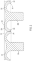
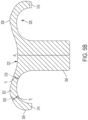
- Prior rivets 100a-b have a shape with a head portion 102 that comprises a narrow leading edge 106 at an angle that can be easily formed on a cold header, but can jam in the channel 130 due to shingling (e.g., overlapping of the head portions 102 in the top region of the channel), as illustrated in FIG. 1 .
- the rivet 100b can contact the channel 130 at points 122 and 120 where a side 102a of the head portion 102 of the rivet 100b can lift up such that the leading edge 106 (as the rivets 100a-b move right to left in the drawing) of the rivet 100b is on top of the head portion 102 of rivet 100a, thereby causing a shingle effect 124 (e.g., wedging of rivets) which can prevent the rivets 100a-b from further movement within the channel 130.
- a shingle effect 124 e.g., wedging of rivets
- an anti-shingle rivet according to the present disclosure which can comprise a blunt outer edge, which may be more difficult to manufacturer (as it, unlike the outer edge of conventional rivets, can be significantly more difficult to form on a cold header), but wherein the blunt outer edge can inhibit or prevent "point-to-point" type of contact on a beveled edge of the rivets which could otherwise result in wedging forces that could lead to jamming in the channels.
- anti-shingle rivets according to the present disclosure can resist shingling and can be fed through the rivet feed channel in a series arrangement and in a preselected orientation such that they can consistently and predictably engage with a rivet holder of a resistance spot rivet welding apparatus.
- the rivets according to the present disclosure can be automatically fed by a cartridge or a blow feeder without, or with less occurrence of, jamming or shingling.
- anti-shingle rivets 200a-b comprising a head portion 202 including a cylindrical or shallow tapered outer edge 206 that may not cause shingling in the rivet delivery system (RDS) are provided herein and illustrated in FIGs. 2 , 3A-C , 4A-4C , and 5A-5B .
- the rivet 200b can contact the channel 230 at points 222 and 220 where a side 202a of the head portion 202 of the rivet 200b can lift up slightly.
- the edge 206 due to the shape and configuration of the edge 206 the shingling effect can be minimized or prevented such that the rivets 200a-b can move through the channel 230 without jamming or shingling.
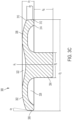
- the anti-shingle rivet 300 can be configured to fasten layers of an assembly together utilizing a resistance spot rivet welding process.
- the anti-shingle rivet 300 comprises a head portion 302 and a shank 304 extending from the head portion 302 along a longitudinal axis, A 1 , of the anti-shingle rivet 300.
- the head portion 302 can be configured for contact by an electrode of a resistance spot rivet welding system.
- the head portion 302 can extend around a periphery of the shank 304 and can comprise, for example, an annular shape.
- a cavity 322 can extend through the head portion 302 and at least partially into the shank 304.
- the cavity 322 can be configured to facilitate contact between the anti-shingle rivet 300 and an electrode of the resistance sport rivet welding system.
- the cavity 322 can be bowl-shaped.
- the head portion 302 of the rivet 300 comprises an outer edge 306.
- the outer edge 306 extends away from the shank 304 and defines an annular-shaped cavity 326.
- a bottom edge 314 of the head portion 302 can be configured to contact a layer of an assembly after installation utilizing a resistance spot rivet welding process.
- the bottom edge 314 of the head portion 302 can be configured to engage/contact a layer of the assembly (e.g., apply a holding force) and minimally, if at all, penetrate through the engaged/contacted layer, while the shank 304 can be configured to pierce and/or melt through the engaged/contacted layer and/or a different layer of the assembly during a resistance spot rivet welding process.
- the shank 304 of the rivet 300 can metallurgically bond to a layer of the assembly after installation.
- the head portion 302 extends a distance, d 1 , along the longitudinal axis, A 1 , of the anti-shingle rivet 300.
- the distance, d 1 can be at least 0.5 mm, such as, for example, at least 1 mm, at least 1.5 mm, at least 2 mm, or at least 3 mm.
- the distance, d 1 can be no greater than 10 mm, such as, for example, no greater than 5 mm, no greater than 4 mm, no greater than 3 mm, no greater than 2 mm, or no greater than 1.5 mm.
- the distance, d 1 can be in a range of 0.5 mm to 10 mm, such as, for example, 0.5 mm to 5 mm, 2 mm to 4 mm, or 1 mm to 2 mm.
- the shank 304 can extend a distance, d 4 , along the longitudinal axis, A 1 .
- the distance d 4 can be at least 1 mm, such as, for example, at least 3mm, at least 4 mm, at least 5 mm, or at least 6 mm.
- the distance, d 4 can be no greater than 30mm, such as, for example, no greater than 20 mm, no greater than 10 mm, no greater than 9 mm, no greater than 8 mm, or no greater than 6 mm.
- the distance, d 4 can be in a range of 1 mm to 30 mm, such as, for example, 3 mm to 30 mm, 5 mm to 25 mm, 10 mm to 20 mm, 4 mm to 9 mm, or 5 mm to 8 mm.
- the shank 304 can comprise a diameter, d 5 , no greater than 10 mm, such as, for example, no greater than 7 mm, no greater than 6 mm, no greater than 5 mm, or no greater than 4 mm, or no greater than 3 mm.
- the shank 304 can comprise a diameter, d 5 , of at least 1 mm, such as, for example, at least 2 mm, at least 3 mm, at least 4 mm, at least 5 mm, at least 6 mm, or at least 7 mm.
- the outer edge 306 can comprise a shallow taper, ⁇ 1 , relative to the longitudinal axis, A 1 .
- the outer edge 306 can minimize or prevent shingling of rivets in a rivet delivery channel.
- the outer edge 306 can be substantially flat and/or substantially aligned with the longitudinal axis, A 1 , of the anti-shingle rivet 300.
- the shallow taper, ⁇ 1 can be less than 15 degrees relative to the longitudinal axis, A 1 , such as, for example, less than 14 degrees, less than 10 degrees, less than 8 degrees, less than 6 degrees, less than 5 degrees, less than 4 degrees, or less than 2 degrees, all relative to the longitudinal axis, A 1 .
- the shallow taper, ⁇ 1 can be at least 0 degrees relative to the longitudinal axis, A 1 , such as, for example, at least 1 degree, at least 2 degrees, at least 4 degrees, at least 5 degrees, at least 6 degrees, at least 8 degrees, or at least 10 degrees, all relative to the longitudinal axis, A 1 .
- the shallow taper, ⁇ 1 can be in a range of 0 degrees to 15 degrees relative to the longitudinal axis, A 1 , such as, for example, 1 degree to 14 degrees, 2 degrees to 14 degrees, 4 degrees to 12 degrees, 5 degrees to 10 degrees, or 6 degrees to 8 degrees, all relative to the longitudinal axis, A 1 .
- the shallow taper, ⁇ 1 can be substantially 0 degrees relative to the longitudinal axis, A 1
- the outer edge 306 can comprise a cylindrical shape.
- the outer edge 306 can be substantially parallel to the longitudinal axis, A 1 .
- the shallow taper, ⁇ 1 can be in a range of greater than 0 degrees to 15 degrees relative to the longitudinal axis, A 1 , and can comprise a frustoconical shape.
- the outer edge 306 can be substantially flat or curved.
- the outer edge 306 can comprise a cylindrical shape, a frustoconical shape, a concave shape, a convex shape, a stepped shaped, or other curved shape.
- the outer edge 306 extends a distance, d 2 , generally in the direction of the longitudinal axis, A 1 , of the rivet 300.
- the distance, d 2 is in a range of 20 percent to 60 percent of the distance, d 1 .
- the distance, d 1 can be 0.115 inch (2.9 mm) or greater.
- the distance, d 1 can be 0.115 inch (2.9mm) and the distance, d 2 , can be 35% of the distance, d 1 .
- the head portion 302 of the anti-shingle rivet 300 can comprise a diameter, d 3 , that is at least 4 mm, such as, for example, at least 5 mm, at least 6 mm, at least 7 mm, at least 10 mm, at least 12 mm, at least 14 mm, at least 15 mm, at least 16 mm, at least 18 mm, at least 20 mm, at least 22 mm, at least 24 mm, or at least 25 mm.
- the head portion 302 of the anti-shingle rivet 300 can comprise a diameter, d 3 , no greater than 30 mm, no greater than 25 mm, no greater than 24 mm, no greater than 22 mm, no greater than 20 mm, no greater than 18 mm, no greater than 16 mm, such as, for example, no greater than 15 mm, no greater than 14 mm, no greater than 12 mm, no greater than 10 mm, or no greater than 7 mm.
- the head portion 302 of the anti-shingle rivet 300 can comprise a diameter, d 3 , in a range of 4 mm to 30 mm, such as, for example, 5 mm to 25 mm, 10 mm to 18 mm, 10 mm to 14 mm, 14 mm to 18 mm, 20 mm to 25 mm, or 12 mm to 14 mm.
- Manufacturing the anti-shingle rivet 300 can balance the difficulty of producing the outer edge 306 and the anti-shingle properties of the outer edge 306. For example, manufacturing the anti-shingle rivet 300 with an outer edge 306 that is cylindrical may enhance minimization or prevention of anti-shingling of rivets in a precision feed channel, while it may also present manufacturing challenges.
- the outer edge 306 can comprise a frustoconical shape and/or a shallow taper that can reduce the difficulty of manufacturing the rivets, but may present challenges with ensuring the rivets do no jam or shingle in the channel.
- the outer edge 306 can be optimized for fast production, such as, for example, a production rate of at least 50 rivets/min, such as, for example, at least 100 rivets/min, at least 200 rivets/min, or at least 220 rivets/min.
- the head portion 302 can comprise an underfill area 312 positioned near the bottom edge 314 of the head portion 302 and intermediate the outer edge 306 and the bottom edge 314.
- the underfill area 312 can be intentionally underfilled during manufacture of the rivet 300 in order to minimize or prevent flash from the production process or other point formation in the underfill area 312 which can inhibit movement of the rivet 300 in a channel. Additionally, the underfill area 312 can be minimized in order to inhibit or prevent the underfill area from becoming a ramp surface that could otherwise cause shingling of rivets.
- a transition 310 can be positioned intermediate the outer edge 306 and an upper surface 308 of the head portion 302.
- the transition 310 can comprise, for example, a radius or a frustoconical shape.
- the anti-shingle rivet 300 can comprise a metal or a metal alloy.
- the anti-shingle rivet 300 can comprise an electrically conductive material suitable to withstand a resistance spot rivet welding process.
- the anti-shingle rivet 300 can comprise at least one of aluminum, an aluminum alloy, iron, an iron alloy, titanium, and a titanium alloy.
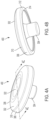
- the anti-shingle rivet 300 can be a wider profile anti-shingle rivet.
- FIGs. 4A-4C a non-limiting embodiment of an alternative configuration of an anti-shingle rivet 400 according to the present disclosure is provided to show an embodiment of such a wider profile anti-shingle rivet.
- the inventors of the present disclosure observed that the stiffness of the head portion of an anti-shingle rivet according to the present disclosure can affect the quality of the weld joint achieved.
- reducing the stiffness of the head portion to accommodate displacement of the head portion relative to the shank can be advantageous.
- the reduced stiffness can enable a portion of the head portion of the anti-shingle rivet to be moved by an upper electrode of a resistance spot rivet welding system relative to the weld joint formed during the resistance spot rivet welding process.
- less compensation may be required by movement of a lower electrode of the resistance sport rivet welding system towards the weld joint, and more desirable fusion of the anti-shingle rivet to the assembly may be achieved.
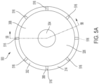
- an anti-shingle rivet 500 is provided with reduced stiffness in the head portion 302.
- the reduced stiffness can enable a higher quality weld joint and more desirable fusion of the anti-shingle rivet 500 to an assembly relative to substantially identical rivets lacking the reduced stiffness.
- the anti-shingle rivet 500 comprises a first portion 518 of the head portion 302 having a first thickness, t 1 , and a second portion 520 having a second thickness, t 2 .
- the first thickness, t 1 is less than the second thickness, t 2 , and the thickness difference reduces stiffness in the head portion 302.
- the anti-shingle rivet comprises a plurality of notches 516 configured to aid in dispersion of gas and material during a resistance spot rivet welding process.
- the notches 516 may be spaced apart along the bottom edge 314 around the periphery of the head portion 302.
Landscapes
- Engineering & Computer Science (AREA)
- General Engineering & Computer Science (AREA)
- Mechanical Engineering (AREA)
- Insertion Pins And Rivets (AREA)
- Connection Of Plates (AREA)
Claims (13)
- Niet (300), der zur Verwendung in einem Nietzuführkanal eines Nietzuführsystems geeignet ist, wobei der Niet Folgendes umfasst:einen Kopfabschnitt (302), der sich um eine erste Strecke (d1) entlang einer Längsachse (A1) des Niets erstreckt, wobei der Kopfabschnitt Folgendes umfasst:
eine Außenkante (306), die einen ringförmigen ersten Hohlraum (326) definiert und so eingerichtet ist, dass sie eine Schuppenbildung in einem Nietzuführkanal eines Nietzuführsystems verhindert, wobei sich die Außenkante über eine zweite Strecke (d2) entlang der Längsachse des Niets erstreckt, wobei die zweite Strecke in einem Bereich von 20 Prozent bis 60 Prozent der ersten Strecke liegt; undeinen Schaft (304), der sich von dem Kopfabschnitt erstreckt, wobei sich ein zweiter Hohlraum (322) durch den Kopfabschnitt und zumindest teilweise in den Schaft erstreckt. - Niet (300) nach Anspruch 1, wobei die Außenkante (306) zylindrisch ist oder eine Verjüngung (α1) in einem Bereich von 0 Grad bis 15 Grad relativ zu der Längsachse (A1) des Niets umfasst.
- Niet (300) nach Anspruch 1 oder Anspruch 2, wobei die zweite Strecke (d2) in einem Bereich von 30 Prozent bis 40 Prozent der ersten Strecke (d1) liegt.
- Niet (300) nach einem der Ansprüche 1 bis 3, wobei die Außenkante (306) im Wesentlichen flach ist oder wobei die Außenkante gekrümmt ist.
- Niet (300) nach einem der Ansprüche 1 bis 4, wobei der Kopfabschnitt (302) einen Unterfüllungsbereich (312) zwischen der Außenkante (306) und einer Unterkante (314) des Kopfabschnitts umfasst.
- Niet (300) nach einem der Ansprüche 1 bis 5, wobei der Kopfabschnitt (302) einen Übergang (310) zwischen der Außenkante (306) und einer oberen Fläche (308) des Kopfabschnitts umfasst, wobei der Übergang vorzugsweise einen Radius oder eine kegelstumpfförmige Form umfasst.
- Niet (300) nach einem der Ansprüche 1 bis 6, wobei sich der Kopfabschnitt (302) um einen Umfang des Schafts (304) erstreckt und einen ersten Abschnitt (518) mit einer ersten Dicke (t1) und einen zweiten Abschnitt (520) mit einer zweiten Dicke (t2) umfasst, wobei die erste Dicke geringer ist als die zweite Dicke, und wobei der erste Abschnitt zwischen dem zweiten Abschnitt und dem Schaft liegt.
- Niet (300) nach einem der Ansprüche 1 bis 7, wobei der Niet durch eine Kartusche oder eine Blaszuführung automatisch zugeführt werden kann, ohne zu verklemmen.
- Niet (300) nach einem der Ansprüche 1 bis 8, wobei der Niet zur Verwendung in einem Widerstandspunktnietsystem eingerichtet ist.
- Verfahren zur Herstellung, umfassend das Herstellen von mindestens 50 oder mindestens 100 der Niete (300) nach einem der Ansprüche 1 bis 9 pro Minute.
- Niet (300) nach Anspruch 7, wobei die erste Dicke (t1) um mindestens 0,1 mm geringer ist als die zweite Dicke (t2).
- Niet (300) nach Anspruch 7 oder Anspruch 11, wobei der Kopfabschnitt (302) mindestens eines von einem gestuften Profil, einem sich verjüngenden Profil und einem gekrümmten Profil umfasst.
- Niet (300) nach Anspruch 1, wobei die Außenkante (306) stumpf und so eingerichtet ist, dass sie Punkt-zu-Punkt-Kontakt an einer abgeschrägten Kante verhindert, wodurch Verkeilungskräfte, die zu einem Verklemmen der Niete in Präzisionszuführungsbahnen führen, verhindert werden.
Applications Claiming Priority (3)
| Application Number | Priority Date | Filing Date | Title |
|---|---|---|---|
| US202062989108P | 2020-03-13 | 2020-03-13 | |
| US202063018941P | 2020-05-01 | 2020-05-01 | |
| PCT/US2021/020912 WO2021183366A1 (en) | 2020-03-13 | 2021-03-04 | Anti-shingle rivets |
Publications (4)
| Publication Number | Publication Date |
|---|---|
| EP4118347A1 EP4118347A1 (de) | 2023-01-18 |
| EP4118347A4 EP4118347A4 (de) | 2024-04-24 |
| EP4118347B1 true EP4118347B1 (de) | 2025-06-25 |
| EP4118347C0 EP4118347C0 (de) | 2025-06-25 |
Family
ID=77671935
Family Applications (1)
| Application Number | Title | Priority Date | Filing Date |
|---|---|---|---|
| EP21767973.7A Active EP4118347B1 (de) | 2020-03-13 | 2021-03-04 | Anti-schindel-nieten |
Country Status (7)
| Country | Link |
|---|---|
| US (1) | US12078196B2 (de) |
| EP (1) | EP4118347B1 (de) |
| JP (1) | JP2023518003A (de) |
| AU (1) | AU2021235735B2 (de) |
| BR (1) | BR112022015458A2 (de) |
| ES (1) | ES3036599T3 (de) |
| WO (1) | WO2021183366A1 (de) |
Family Cites Families (19)
| Publication number | Priority date | Publication date | Assignee | Title |
|---|---|---|---|---|
| US3587842A (en) * | 1969-11-10 | 1971-06-28 | Spotnails | Cartridge of collated fasteners |
| US3900132A (en) * | 1973-09-27 | 1975-08-19 | Trw Inc | Apparatus for handling parts |
| JPS60123416U (ja) * | 1984-01-30 | 1985-08-20 | 不二自動車工業株式会社 | リベツト |
| KR20020047269A (ko) * | 1999-10-26 | 2002-06-21 | 사이토 아키히코 | 리벳, 리벳 결합구조체, 리벳고정 장치 및 리벳고정 방법 |
| US6494322B1 (en) * | 2000-10-31 | 2002-12-17 | G. Lyle Habermehl | Arrow head screwstrip |
| US7051875B2 (en) * | 2003-12-17 | 2006-05-30 | Simpson Strong-Tie Company, Inc. | Holding strap for curved screwstrip |
| DE102008031121A1 (de) * | 2008-05-06 | 2009-11-12 | Daimler Ag | Schweißnietverbindung |
| JP5382340B2 (ja) * | 2009-11-11 | 2014-01-08 | ポップリベット・ファスナー株式会社 | ブラインドリベット |
| GB2482162B (en) * | 2010-07-22 | 2012-08-01 | Avdel Uk Ltd | Externally splined fastener |
| DE102012010870A1 (de) * | 2012-05-31 | 2013-12-05 | Böllhoff Verbindungstechnik GmbH | Schweißhilfsfügeteil und Verfahren zum Verbinden von Bauteilen mit diesem Schweißhilfsfügeteil |
| CN202811734U (zh) * | 2012-09-21 | 2013-03-20 | 温州聚星电接触科技有限公司 | 一种倒角复合铆钉 |
| US8985923B2 (en) * | 2013-03-13 | 2015-03-24 | Alcoa Inc. | Blind Fastener |
| JP5722479B2 (ja) * | 2013-07-22 | 2015-05-20 | 株式会社神戸製鋼所 | 異材接合用リベット、異材接合用部材、異材接合体の製造方法及び異材接合体 |
| CN106163721B (zh) * | 2014-02-03 | 2021-10-15 | 豪梅特航空航天有限公司 | 电阻焊接紧固件、装置和方法 |
| JP6710765B2 (ja) * | 2016-03-25 | 2020-06-17 | アーコニック インコーポレイテッドArconic Inc. | 異種材料を接合するための抵抗溶接ファスナー、装置及び方法、並びにそれにより製造される接合部の評価 |
| US10590979B2 (en) * | 2017-01-24 | 2020-03-17 | Ford Global Technologies, Llc | Corrosion protection for mechanical joints |
| US20180283423A1 (en) * | 2017-03-30 | 2018-10-04 | Ford Global Technologies, Llc | Self-piercing rivet with a concave lower surface |
| CN111182995B (zh) * | 2017-12-14 | 2022-02-18 | 豪梅特航空航天有限公司 | 用于紧固件馈送装置的夹套组件 |
| CN114233733B (zh) * | 2021-11-12 | 2022-11-01 | 上海交通大学 | 用于形成板材平底铆接的改进结构铆钉 |
-
2021
- 2021-03-04 AU AU2021235735A patent/AU2021235735B2/en active Active
- 2021-03-04 US US17/760,405 patent/US12078196B2/en active Active
- 2021-03-04 BR BR112022015458A patent/BR112022015458A2/pt unknown
- 2021-03-04 JP JP2022554899A patent/JP2023518003A/ja active Pending
- 2021-03-04 ES ES21767973T patent/ES3036599T3/es active Active
- 2021-03-04 WO PCT/US2021/020912 patent/WO2021183366A1/en not_active Ceased
- 2021-03-04 EP EP21767973.7A patent/EP4118347B1/de active Active
Also Published As
| Publication number | Publication date |
|---|---|
| WO2021183366A1 (en) | 2021-09-16 |
| BR112022015458A2 (pt) | 2022-10-04 |
| ES3036599T3 (en) | 2025-09-22 |
| AU2021235735B2 (en) | 2023-12-21 |
| AU2021235735A1 (en) | 2022-09-01 |
| EP4118347A4 (de) | 2024-04-24 |
| EP4118347A1 (de) | 2023-01-18 |
| US12078196B2 (en) | 2024-09-03 |
| US20230073533A1 (en) | 2023-03-09 |
| JP2023518003A (ja) | 2023-04-27 |
| EP4118347C0 (de) | 2025-06-25 |
Similar Documents
| Publication | Publication Date | Title |
|---|---|---|
| US12347988B2 (en) | Resistance welding fastener, apparatus and methods | |
| US12097568B2 (en) | Resistance welding fastener, apparatus and methods for joining similar and dissimilar materials | |
| EP3401055B1 (de) | Niet für reibungsstanznieten und verbindungssystem für reibungsstanznieten | |
| US8250728B2 (en) | Method of joining with self-piercing rivet and assembly | |
| EP2024651B2 (de) | Selbststanznietung | |
| US9316243B2 (en) | Method for forming a joint in a stack of light metal alloy sheets | |
| EP2754519B1 (de) | Schneidewerkzeug mit austauschbarem kopf | |
| EP3900868B1 (de) | Verbindungsverfahren | |
| CN104684664A (zh) | 一种利用自穿孔铆钉形成接头的方法 | |
| US20230311197A1 (en) | Method of forming a riveted joint | |
| EP4118347B1 (de) | Anti-schindel-nieten | |
| EP3287226B1 (de) | Linear reibschweissverfahren von werkstücken | |
| EP2640545B1 (de) | Kombination einer kontaktdüse und eines schweissdrahtes, und verfaren zum metallgas-lichtbogen-schweissen auf einer schweissoberfläche | |
| US12337406B2 (en) | Contoured electrodes for joining workpieces with curved surfaces | |
| US11802581B1 (en) | Methods for fastening | |
| US20250180055A1 (en) | Self-Piercing Rivet and Methods of Making and Using Same | |
| WO2025083023A1 (en) | Semi-hollow self-piercing rivet and joining method using same |
Legal Events
| Date | Code | Title | Description |
|---|---|---|---|
| STAA | Information on the status of an ep patent application or granted ep patent |
Free format text: STATUS: THE INTERNATIONAL PUBLICATION HAS BEEN MADE |
|
| PUAI | Public reference made under article 153(3) epc to a published international application that has entered the european phase |
Free format text: ORIGINAL CODE: 0009012 |
|
| STAA | Information on the status of an ep patent application or granted ep patent |
Free format text: STATUS: REQUEST FOR EXAMINATION WAS MADE |
|
| 17P | Request for examination filed |
Effective date: 20220809 |
|
| AK | Designated contracting states |
Kind code of ref document: A1 Designated state(s): AL AT BE BG CH CY CZ DE DK EE ES FI FR GB GR HR HU IE IS IT LI LT LU LV MC MK MT NL NO PL PT RO RS SE SI SK SM TR |
|
| DAV | Request for validation of the european patent (deleted) | ||
| DAX | Request for extension of the european patent (deleted) | ||
| A4 | Supplementary search report drawn up and despatched |
Effective date: 20240321 |
|
| RIC1 | Information provided on ipc code assigned before grant |
Ipc: B23K 11/00 20060101ALI20240315BHEP Ipc: F16B 19/08 20060101AFI20240315BHEP |
|
| GRAP | Despatch of communication of intention to grant a patent |
Free format text: ORIGINAL CODE: EPIDOSNIGR1 |
|
| STAA | Information on the status of an ep patent application or granted ep patent |
Free format text: STATUS: GRANT OF PATENT IS INTENDED |
|
| INTG | Intention to grant announced |
Effective date: 20250318 |
|
| GRAS | Grant fee paid |
Free format text: ORIGINAL CODE: EPIDOSNIGR3 |
|
| GRAA | (expected) grant |
Free format text: ORIGINAL CODE: 0009210 |
|
| STAA | Information on the status of an ep patent application or granted ep patent |
Free format text: STATUS: THE PATENT HAS BEEN GRANTED |
|
| AK | Designated contracting states |
Kind code of ref document: B1 Designated state(s): AL AT BE BG CH CY CZ DE DK EE ES FI FR GB GR HR HU IE IS IT LI LT LU LV MC MK MT NL NO PL PT RO RS SE SI SK SM TR |
|
| REG | Reference to a national code |
Ref country code: GB Ref legal event code: FG4D |
|
| REG | Reference to a national code |
Ref country code: CH Ref legal event code: EP |
|
| REG | Reference to a national code |
Ref country code: CH Ref legal event code: EP |
|
| REG | Reference to a national code |
Ref country code: IE Ref legal event code: FG4D |
|
| REG | Reference to a national code |
Ref country code: DE Ref legal event code: R096 Ref document number: 602021032925 Country of ref document: DE |
|
| U01 | Request for unitary effect filed |
Effective date: 20250626 |
|
| U07 | Unitary effect registered |
Designated state(s): AT BE BG DE DK EE FI FR IT LT LU LV MT NL PT RO SE SI Effective date: 20250702 |
|
| REG | Reference to a national code |
Ref country code: ES Ref legal event code: FG2A Ref document number: 3036599 Country of ref document: ES Kind code of ref document: T3 Effective date: 20250922 |
|
| PG25 | Lapsed in a contracting state [announced via postgrant information from national office to epo] |
Ref country code: NO Free format text: LAPSE BECAUSE OF FAILURE TO SUBMIT A TRANSLATION OF THE DESCRIPTION OR TO PAY THE FEE WITHIN THE PRESCRIBED TIME-LIMIT Effective date: 20250925 Ref country code: GR Free format text: LAPSE BECAUSE OF FAILURE TO SUBMIT A TRANSLATION OF THE DESCRIPTION OR TO PAY THE FEE WITHIN THE PRESCRIBED TIME-LIMIT Effective date: 20250926 |
|
| PG25 | Lapsed in a contracting state [announced via postgrant information from national office to epo] |
Ref country code: HR Free format text: LAPSE BECAUSE OF FAILURE TO SUBMIT A TRANSLATION OF THE DESCRIPTION OR TO PAY THE FEE WITHIN THE PRESCRIBED TIME-LIMIT Effective date: 20250625 |
|
| PG25 | Lapsed in a contracting state [announced via postgrant information from national office to epo] |
Ref country code: RS Free format text: LAPSE BECAUSE OF FAILURE TO SUBMIT A TRANSLATION OF THE DESCRIPTION OR TO PAY THE FEE WITHIN THE PRESCRIBED TIME-LIMIT Effective date: 20250925 |
|
| PG25 | Lapsed in a contracting state [announced via postgrant information from national office to epo] |
Ref country code: IS Free format text: LAPSE BECAUSE OF FAILURE TO SUBMIT A TRANSLATION OF THE DESCRIPTION OR TO PAY THE FEE WITHIN THE PRESCRIBED TIME-LIMIT Effective date: 20251025 |
|
| PG25 | Lapsed in a contracting state [announced via postgrant information from national office to epo] |
Ref country code: SM Free format text: LAPSE BECAUSE OF FAILURE TO SUBMIT A TRANSLATION OF THE DESCRIPTION OR TO PAY THE FEE WITHIN THE PRESCRIBED TIME-LIMIT Effective date: 20250625 |
|
| PG25 | Lapsed in a contracting state [announced via postgrant information from national office to epo] |
Ref country code: CZ Free format text: LAPSE BECAUSE OF FAILURE TO SUBMIT A TRANSLATION OF THE DESCRIPTION OR TO PAY THE FEE WITHIN THE PRESCRIBED TIME-LIMIT Effective date: 20250625 |
|
| PG25 | Lapsed in a contracting state [announced via postgrant information from national office to epo] |
Ref country code: PL Free format text: LAPSE BECAUSE OF FAILURE TO SUBMIT A TRANSLATION OF THE DESCRIPTION OR TO PAY THE FEE WITHIN THE PRESCRIBED TIME-LIMIT Effective date: 20250625 |
|
| PG25 | Lapsed in a contracting state [announced via postgrant information from national office to epo] |
Ref country code: SK Free format text: LAPSE BECAUSE OF FAILURE TO SUBMIT A TRANSLATION OF THE DESCRIPTION OR TO PAY THE FEE WITHIN THE PRESCRIBED TIME-LIMIT Effective date: 20250625 |