EP4117854B1 - Hubkolben-brennkraftmaschine - Google Patents
Hubkolben-brennkraftmaschine Download PDFInfo
- Publication number
- EP4117854B1 EP4117854B1 EP21707665.2A EP21707665A EP4117854B1 EP 4117854 B1 EP4117854 B1 EP 4117854B1 EP 21707665 A EP21707665 A EP 21707665A EP 4117854 B1 EP4117854 B1 EP 4117854B1
- Authority
- EP
- European Patent Office
- Prior art keywords
- reciprocating
- internal combustion
- combustion engine
- piston
- pin structure
- Prior art date
- Legal status (The legal status is an assumption and is not a legal conclusion. Google has not performed a legal analysis and makes no representation as to the accuracy of the status listed.)
- Active
Links
Images




Classifications
-
- F—MECHANICAL ENGINEERING; LIGHTING; HEATING; WEAPONS; BLASTING
- F02—COMBUSTION ENGINES; HOT-GAS OR COMBUSTION-PRODUCT ENGINE PLANTS
- F02B—INTERNAL-COMBUSTION PISTON ENGINES; COMBUSTION ENGINES IN GENERAL
- F02B9/00—Engines characterised by other types of ignition
- F02B9/06—Engines characterised by other types of ignition with non-timed positive ignition, e.g. with hot-spots
-
- F—MECHANICAL ENGINEERING; LIGHTING; HEATING; WEAPONS; BLASTING
- F02—COMBUSTION ENGINES; HOT-GAS OR COMBUSTION-PRODUCT ENGINE PLANTS
- F02B—INTERNAL-COMBUSTION PISTON ENGINES; COMBUSTION ENGINES IN GENERAL
- F02B1/00—Engines characterised by fuel-air mixture compression
- F02B1/12—Engines characterised by fuel-air mixture compression with compression ignition
-
- F—MECHANICAL ENGINEERING; LIGHTING; HEATING; WEAPONS; BLASTING
- F02—COMBUSTION ENGINES; HOT-GAS OR COMBUSTION-PRODUCT ENGINE PLANTS
- F02B—INTERNAL-COMBUSTION PISTON ENGINES; COMBUSTION ENGINES IN GENERAL
- F02B11/00—Engines characterised by both fuel-air mixture compression and air compression, or characterised by both positive ignition and compression ignition, e.g. in different cylinders
-
- F—MECHANICAL ENGINEERING; LIGHTING; HEATING; WEAPONS; BLASTING
- F02—COMBUSTION ENGINES; HOT-GAS OR COMBUSTION-PRODUCT ENGINE PLANTS
- F02B—INTERNAL-COMBUSTION PISTON ENGINES; COMBUSTION ENGINES IN GENERAL
- F02B23/00—Other engines characterised by special shape or construction of combustion chambers to improve operation
- F02B23/02—Other engines characterised by special shape or construction of combustion chambers to improve operation with compression ignition
- F02B23/06—Other engines characterised by special shape or construction of combustion chambers to improve operation with compression ignition the combustion space being arranged in working piston
- F02B23/0645—Details related to the fuel injector or the fuel spray
- F02B23/0648—Means or methods to improve the spray dispersion, evaporation or ignition
- F02B23/0651—Means or methods to improve the spray dispersion, evaporation or ignition the fuel spray impinging on reflecting surfaces or being specially guided throughout the combustion space
-
- F—MECHANICAL ENGINEERING; LIGHTING; HEATING; WEAPONS; BLASTING
- F02—COMBUSTION ENGINES; HOT-GAS OR COMBUSTION-PRODUCT ENGINE PLANTS
- F02B—INTERNAL-COMBUSTION PISTON ENGINES; COMBUSTION ENGINES IN GENERAL
- F02B23/00—Other engines characterised by special shape or construction of combustion chambers to improve operation
- F02B23/02—Other engines characterised by special shape or construction of combustion chambers to improve operation with compression ignition
- F02B23/06—Other engines characterised by special shape or construction of combustion chambers to improve operation with compression ignition the combustion space being arranged in working piston
- F02B23/0678—Unconventional, complex or non-rotationally symmetrical shapes of the combustion space, e.g. flower like, having special shapes related to the orientation of the fuel spray jets
-
- F—MECHANICAL ENGINEERING; LIGHTING; HEATING; WEAPONS; BLASTING
- F02—COMBUSTION ENGINES; HOT-GAS OR COMBUSTION-PRODUCT ENGINE PLANTS
- F02F—CYLINDERS, PISTONS OR CASINGS, FOR COMBUSTION ENGINES; ARRANGEMENTS OF SEALINGS IN COMBUSTION ENGINES
- F02F3/00—Pistons
- F02F3/26—Pistons having combustion chamber in piston head
-
- F—MECHANICAL ENGINEERING; LIGHTING; HEATING; WEAPONS; BLASTING
- F02—COMBUSTION ENGINES; HOT-GAS OR COMBUSTION-PRODUCT ENGINE PLANTS
- F02F—CYLINDERS, PISTONS OR CASINGS, FOR COMBUSTION ENGINES; ARRANGEMENTS OF SEALINGS IN COMBUSTION ENGINES
- F02F3/00—Pistons
- F02F3/28—Other pistons with specially-shaped head
- F02F3/285—Other pistons with specially-shaped head the head being provided with an insert located in or on the combustion-gas-swept surface
-
- Y—GENERAL TAGGING OF NEW TECHNOLOGICAL DEVELOPMENTS; GENERAL TAGGING OF CROSS-SECTIONAL TECHNOLOGIES SPANNING OVER SEVERAL SECTIONS OF THE IPC; TECHNICAL SUBJECTS COVERED BY FORMER USPC CROSS-REFERENCE ART COLLECTIONS [XRACs] AND DIGESTS
- Y02—TECHNOLOGIES OR APPLICATIONS FOR MITIGATION OR ADAPTATION AGAINST CLIMATE CHANGE
- Y02T—CLIMATE CHANGE MITIGATION TECHNOLOGIES RELATED TO TRANSPORTATION
- Y02T10/00—Road transport of goods or passengers
- Y02T10/10—Internal combustion engine [ICE] based vehicles
- Y02T10/12—Improving ICE efficiencies
Definitions
- the invention relates to a reciprocating piston internal combustion engine and a motor vehicle, for example a commercial vehicle, with such a reciprocating piston internal combustion engine.
- HCCI Homogeneous Charge Compression Ignition
- HCCI results in increased fuel ingress into the oil and increased emissions of CO and HC. Furthermore, controlling the ignition timing is very complex and sensitive to exhaust gas recirculation rates. As a result, homogeneous diesel combustion approaches are only suitable for the lower and medium partial load ranges. Due to these difficulties and the increased performance of exhaust gas aftertreatment, HCCI approaches have not been able to prevail in practice.
- the JP H08 4534 A discloses a combustion chamber in which fuel injected from an injection nozzle strikes protruding parts so that the mixing properties of the injected fuel and the air are improved.
- the protruding parts are provided on the underside of an opening surrounding the injection nozzle and protrude into the flow path of the fuel jet injected from the injection nozzle.
- the US 2006/0081212 A1 shows a combustion chamber of an internal combustion engine in which an obstacle is inserted to create turbulence and break up or interrupt soot-rich zones within a directly injected, burning fuel mass. To do this, a ring is introduced into the combustion chamber that interrupts or influences the injected fuel jet.
- the JP H09 88609 A discloses a device for distributing an injected fuel jet evenly in a combustion chamber of an internal combustion engine.
- a cylindrical grid is fixed to the cylinder head in such a way that the grid surrounds the injection nozzle.
- a disk-shaped collision plate is arranged in the combustion chamber in such a way that the lower opening of the grid arrangement is sealed.
- the EP 0 147 149 A2 shows a piston for use in cylinders of internal combustion engines with positive or compression ignition.
- a series of interrupted ribs running along of arcs of increasing radius protrude above the surface of the piston crown to promote turbulence of the unburned charge as the flame spreads.
- the GB 2 254 372 A discloses a design of a piston crown of a spark-ignition internal combustion engine.
- the outer circumference of the piston crown is provided with protruding heat exchanger fins in order to increase the heat transfer surface between the end gases and the piston, wherein the gaps between the fins are sufficiently large so that the combustion flame can spread between the fins without being weakened.
- the FR 2 291 361 A1 relates to a valve-controlled internal combustion engine of the single-cylinder or multi-cylinder type with fuel injection.
- a piston fitted with piston rings and oil control rings slides in each cylinder and has a recess on its front face.
- the purpose of the recesses in the piston surface is to enable stratified charge operation in internal combustion engines.
- the EP 3 351 779 A1 shows a control device for an internal combustion engine with a fuel injection valve and an actuator.
- the fuel injection valve injects fuel directly into a combustion chamber.
- the actuator is configured to change the oxygen concentration in the intake gas supplied to the combustion chamber of the internal combustion engine.
- the object of the invention is in particular to provide a reciprocating piston internal combustion engine which produces fewer pollutants during combustion and preferably also enables a reduction in CO2.
- a reciprocating piston internal combustion engine comprising at least one cylinder in which a reciprocating piston is arranged so as to be movable back and forth.
- Each cylinder has a combustion chamber that can be compressed by the movement of the piston.
- the reciprocating piston internal combustion engine is characterized in that a pin structure is arranged or provided on the combustion chamber side in the area of the cylinder head and/or the piston crown.
- the pin structure according to the invention offers the particular advantage that the same effects as with homogeneous combustion can be achieved, i.e. the formation of pollutants during the combustion process can be largely avoided.
- the pin-like structure enables the formation of a homogeneous temperature field - consistently below the formation temperature of nitrogen oxides and consistently high enough for the complete oxidation of HC and CO.
- the pin-like structure also avoids the disadvantages of a porous burner, since the pin-like structure can be designed to be sufficiently stable, so that it is suitable for practical use in internal combustion engines.
- the provision of a pin-like structure in the combustion chamber of an internal combustion engine according to the invention thus enables an advantageous approximation to the principle of homogeneous combustion.
- the pin-like structure does enable a largely homogeneous temperature field, so that essentially the same effects and advantages as with homogeneous combustion can be achieved.
- a late injection strategy maintains control of the ignition timing and the hot pin structure promotes rapid mixture formation.
- Combustion then preferably takes place entirely within the combustion chamber provided with pins, so that this special design of the combustion chamber can prevent or at least greatly reduce the formation of pollutants during combustion. Hot gas continuously flows out of the combustion chamber for the working process.
- a pin structure is understood to mean a pin-like structure having several or a plurality of pins and/or a device formed by several pins.
- pin can include all slender structures whose longitudinal dimension is greater than their diameter at the thinnest point. In the case of non-elliptical cross-sections, the height is greater than the thinnest wall thickness.
- the pin structure comprises in particular pins whose longitudinal extension is longer than their diameter.
- the pins of the pin structure can be cylindrical and/or bolt-shaped, i.e. have a circular cross-section with respect to a cutting plane that is perpendicular to the direction of movement of the piston.
- the pins can also have a rectangular, a sickle-shaped, a star-shaped and/or another cross-section in this cutting plane.
- the pins of the pin structure can optionally extend parallel or substantially parallel to the direction of movement of the piston.
- the pin structure can be designed to have a heat-storing and/or temperature-balancing effect over its surface during combustion in the combustion chamber.
- the pin structure can be a pin structure for homogenizing mixture formation and/or combustion or at least for promoting more homogeneous mixture formation and/or combustion in the combustion chamber. Homogenization of mixture formation or combustion is not understood here to mean perfect or ideal homogenization. Rather, the pin structure leads to more homogeneous mixture formation or combustion compared to conventional combustion chambers without a pin structure, so that the advantages and positive effects of ideal homogenization, such as the reduction of NOx, can at least be approximated here.
- the pins have a temperature-balancing effect due to their surface. Hot areas, so-called hotspots, are cooled down and temperature drops are heated up. This behavior affects the formation mechanisms of individual pollutant components. The formation temperature of thermal nitrogen oxides is not exceeded locally either. Temperature drops - the cause of CO and HC emissions - are thus avoided.
- the process is in principle suitable for any fuel that can be fed into the system in sufficient quantities with a late injection strategy.
- the pin structure is arranged such that it is located in the compression chamber of the combustion chamber when the piston is at top dead center (hereinafter referred to as TDC), i.e. in the TDC position.
- TDC top dead center
- the pin structure is arranged in a region of the combustion chamber in which combustion of the compressed air-fuel mixture takes place.
- the pin structure is preferably arranged in and/or within the compression chamber of the combustion chamber, at least at the time when the piston is at TDC.
- the pin structure fills a volume proportion in the range of 5% to 40% of the combustion chamber when the piston is at TDC.
- the pin structure fills a volume proportion in the range of 5% to 40% of the compression chamber. This means that in this embodiment, 60% to 95% of the volume proportion of the compression chamber is filled by the combustion mixture or air.
- a variant of this embodiment is particularly advantageous in which the pin structure fills a volume proportion in the range of 10% to 20% of the combustion chamber when the piston is at TDC.
- the pin structure according to this variant fills a volume proportion in the range of 10% to 20% of the compression chamber.
- 80% to 90% of the volume proportion of the compression chamber is filled with combustion mixture or air.
- these areas are particularly advantageous in order to achieve or at least approximate a homogenization of the mixture formation and/or the combustion in the combustion chamber.
- the pin structure can be arranged on the combustion chamber side in the area of the piston crown.
- the pin structure is arranged in a recess in the piston crown. This enables a particularly compact design of the cylinder-piston arrangement.
- the piston is designed as a recessed piston.
- the pin structure can extend in the direction of the combustion chamber in a stalagmite-like manner, i.e. extending from the piston crown to the cylinder head in the shape of a pin, e.g. rod-like, columnar or conical, into the combustion chamber.
- the pin structure can be arranged on the combustion chamber side in the area of the cylinder head.
- the pin structure is arranged in a recess in the cylinder head.
- the pin structure can also be arranged below the cylinder head.
- the term "Below” refers to a normal installation position of the engine, ie the cylinder head is located above the piston and the cylinder jacket in relation to the direction of gravity.
- the pin structure can extend from the cylinder head towards the combustion chamber in a stalactite-like manner, ie starting from an area in or below the cylinder head, it can extend into the combustion chamber in a pin-like manner, e.g. rod-like, column-like or conical shape.
- the pin structure can comprise at least 10 pins. It is also preferably conceivable that the pin structure comprises at least 20 or at least 30 pins or at least 40 pins.
- the number of pins can be appropriately determined for a specific reciprocating piston internal combustion engine taking the following considerations into account. On the one hand, in practice, the combustion chamber diameter or the engine size influences the number of pins. It should also be noted that, on the one hand, the smallest possible pin diameter is desirable. This is because the smaller the pin diameter, the higher the number of pins and thus the larger the surface of the pin structure for the heat-storing and/or temperature-balancing effect. On the other hand, the pin diameters must not be chosen so small that the stability of the pin structure is endangered during operation of the reciprocating piston internal combustion engine. The number of pins can be determined and optimized through suitable tests.
- the multiple pins of the pin structure can be spaced apart from one another, preferably such that the pins are arranged in the combustion chamber without being connected to one another. This prevents the pins from becoming distorted and breaking.
- the reciprocating piston internal combustion engine has an impact pin arranged in the area of the pin structure for deflecting and/or distributing introduced fuel towards the pin structure.
- This enables the introduction of fuel at a more acute angle of introduction, e.g. at a more acute injection angle for liquid fuel or a more acute injection angle for gaseous fuel, than is otherwise usual.
- the fuel is introduced in such a way that it at least partially hits the impact pin and is deflected from there towards the pin structure. This enables particularly efficient fuel distribution in the combustion chamber and prevents fuel from penetrating the annular gap between the piston and the cylinder liner.
- the impact pin is arranged and designed in relation to an introduction direction of the fuel into the combustion chamber and the pin structure in such a way that introduced fuel at least predominantly impacts the impact pin and is deflected by it in a radial direction towards the pin structure and/or
- the impact pin can be arranged in a central region of the pin structure.
- the impact pin can have a lower height in relation to the direction of movement of the piston than the pin structure.
- the pin structure can be made of a metallic material, which allows for advantageous production. Furthermore, the pin structure can be made of a ceramic material, which is particularly advantageous from a thermal point of view. It is also conceivable that the pin structure is made of a composite material, preferably of a metallic material and a ceramic material.
- the reciprocating piston internal combustion engine is designed to supply a fuel required for a combustion process to the combustion chamber under pressure in just one injection process shortly before or when the TDC is reached.
- it can be an air-compressing engine with later direct fuel supply, i.e. near the TDC.
- the reciprocating piston internal combustion engine can be designed to enable partially homogeneous combustion by dividing the mixture formation.
- the reciprocating piston internal combustion engine can be designed to a) supply a partial amount of a fuel required for a combustion process to the combustion chamber to form a lean, non-ignitable mixture, b) subsequently compress the lean, non-ignitable mixture by a piston movement towards TDC and c) then supply a residual amount of the fuel required for a combustion process in the region of TDC to initiate self-ignition or external ignition.
- This alternative embodiment i.e.
- the inventive approach of providing a pin structure to promote the homogenization of the mixture formation and combustion in the combustion chamber is not limited to a specific internal combustion engine.
- the internal combustion engine can be one that runs on gaseous or liquid fuel, for example one that runs on diesel fuel. or gasoline-powered internal combustion engine.
- the internal combustion engine according to a particularly highlighted embodiment is a reciprocating piston internal combustion engine as described above.
- the invention is basically applicable to any internal combustion engine in which a working gas is compressed, heat is released by burning an admixed fuel and a volume expansion generated as a result of the combustion is used to generate mechanical work.
- a device for converting heat into work is thus provided, wherein a gaseous or liquid fuel is mixed with a compressible working gas and can subsequently be burned and wherein the volume expansion generated during combustion can be converted into mechanical work and wherein a pin-like structure is arranged in the combustion chamber of the device such that the combustion takes place within or predominantly within the pin-like structure.
- the pin-like structure can have features of the optional embodiments described above, such as the number of pins, the volume proportion of the pin structure in relation to the amount of air in the combustion chamber, etc.
- the invention further relates to a motor vehicle with a device for converting heat into work, preferably a reciprocating piston internal combustion engine, having the pin structure as described in this document.
- the motor vehicle is preferably a commercial vehicle.
- the motor vehicle can be a motor vehicle which, due to its design and equipment, is designed for transporting people, transporting goods or towing trailers.
- the motor vehicle can be a truck, a bus and/or a semitrailer.
- the invention further relates to a machine or a stationary application, e.g. a combined heat and power plant, comprising a reciprocating internal combustion engine having the pin structure as described in this document.
- the invention further relates to vehicles of all types, comprising a reciprocating internal combustion engine having the pin structure as described in this document.
- the vehicle can be a watercraft, e.g. a ship, or an aircraft, e.g. an airplane.
- combustion chamber and “compression chamber” of a cylinder used above are usually understood as follows:
- the combustion chamber (Vb) is the volume enclosed by the cylinder, piston and cylinder head. It depends on the position of the piston, i.e., it is time-dependent during operation.
- the displacement Vh also known as stroke volume, is known to be the enclosed volume for the cylinders of piston engines, which results from the working path of the individual piston stroke and the effective piston cross-sectional area. It therefore defines the volume that is displaced in an engine by the stroke of all pistons.
- Figure 1 shows a highly schematic cross-sectional view of a reciprocating piston internal combustion engine according to an embodiment of the invention. To simplify the illustration, only one of several cylinders 2 of the reciprocating piston internal combustion engine 1 is shown, in which a reciprocating piston 3 is arranged to be movable back and forth.
- the reciprocating piston internal combustion engine 1 is merely an example of a diesel internal combustion engine, the invention not being restricted to this, as already stated above.
- the reciprocating piston 3 is designed as a bowl piston.
- a pin structure 10 is arranged in a bowl 5 of the piston crown 4, which leads to a more homogeneous mixture formation or combustion - compared to conventional combustion chambers without a pin structure - so that the advantages and positive effects of an ideal homogenization, such as the reduction of NOx, can at least be approximated.
- the pin structure 10 has a large number of pins 11.
- the pins have a temperature-balancing effect due to their surface. Hotspots are cooled and temperature drops are heated by the pins 11. This behavior affects the formation mechanisms of individual pollutant components. The formation temperature of thermal nitrogen oxides is not exceeded even locally, and temperature drops - which cause CO and HC emissions - are avoided.
- the process is suitable for any fuel that can be fed into the system in sufficient quantities with a late injection strategy.
- the bolt-shaped pins 11 made of a metallic material are attached at a distance from one another in the piston crown 4 and without any connection to one another in the combustion chamber 7.
- the pins 11 extend parallel to one another in a stalagmite-like manner in the direction of the combustion chamber 7 or parallel to the direction of movement B of the piston 3.
- the pin structure can also be arranged on the combustion chamber side in the area of the cylinder head, as already described above.
- the cylinder head is only indicated schematically here by the dashed line 6.
- the pin structure 10 is arranged in the combustion chamber in such a way that the combustion takes place completely or almost completely within the combustion chamber provided with pins.
- the recess 5 of the piston crown 4 is part of the compression chamber 7a of the combustion chamber 7, in which combustion of the compressed air-fuel mixture takes place.
- Figure 2 shows a cross-sectional view of a piston 3 in a TDC position at the time of a late fuel injection. Cylinder 2 is not shown here, but is as in Figure 1 presented, executed.
- the fuel 8 is supplied from an injection nozzle 9 under high pressure shortly before TDC. In principle, it does not matter which fuel is used. In this case, diesel fuel is injected, for example. The pressure is necessary to supply the entire amount of fuel in a short time.
- the combustion then takes place entirely within the compression chamber 7a provided with pins. Hot gas continuously flows out of the combustion chamber for the working process. Heat from the compression and combustion process is stored in the pins 11. The thermal interaction takes place mainly between air or combustion gas and the pins 11 or the pin structure 10. As already explained above, thermal interaction reduces local temperature peaks and dips in the combustion gas, thus preventing or at least reducing the formation of pollutants.
- An impact pin 12 arranged in the area of the pin structure 10 is provided for deflecting and/or distributing introduced fuel 8 towards the pin structure 10.
- the impact pin 12 is arranged in a central area of the pin structure 10 and is arranged and designed in relation to an introduction direction of the fuel into the combustion chamber and the pin structure 10 such that introduced fuel 8 at least predominantly impacts the impact pin and is deflected and/or distributed by it in a radial direction towards the pin structure 10.
- Figure 1 shows an embodiment with impact pin 12.
- Figure 2 a piston 3 without impact pin.
- Figure 3 shows a top view of a hollow piston 3 with pin structure 10 of the Figure 1 It can be seen that a plurality of pins 11 are arranged in the recess 5 of the piston head 4 in a substantially uniformly distributed manner.
- this is merely an exemplary embodiment.
- holes can be made in the recessed piston 3, into which the pins 11 are then pressed to form the pin structure 10.
- the recessed piston 3 with an integrated pin structure 10 can also be produced as a cast part.
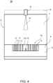
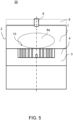
- FIGS. 4 to 6 show an illustration of a combustion process with a reciprocating piston internal combustion engine according to an alternative process with the same combustion chamber principle.
- FIG. 4 outlined compression engine with only later direct Fuel supply near TDC is the fuel supply in the Figures 4 to 6 illustrated alternative processes for partially homogeneous combustion by dividing the mixture formation.
- the reciprocating piston internal combustion engine 30 is designed to initially supply a partial amount of a fuel required for a combustion process to the combustion chamber 7 to form a lean, non-ignitable mixture.
- This is in Figure 4 shown.
- the piston 4 with the pin structure 10 is at bottom dead center (BDC) or close to BDC.
- An early direct centric fuel supply takes place via the injection nozzle 9 while the intake valves are "inlet open” (not shown).
- the aim here is to produce a lean mixture 8a in the middle of the cylinder. This offers the advantage that this centric fuel supply does not result in fuel compression in the annular gap between the cylinder liner and the piston.
- the lean, non-ignitable mixture 8a is subsequently compressed by a piston movement towards the TDC and then a residual amount of the fuel required for a combustion process is supplied in the area of the TDC to initiate the self-ignition or external ignition, which in Figure 6 is illustrated.
- the central injection jet 8 is radially deflected and distributed at the impact pin 12.
- the result is a partially homogenized combustion, which enables reduced pollutant formation without the disadvantage of excessively high pressure gradients due to the dampening effect of the pin structure 10.
- Figure 7 shows a plan view of a hollow piston 4 with an alternative pin structure 20 according to a further embodiment of the invention. It can be seen that a plurality of pins 21, 22, 23, 24 are arranged in the hollow 5 of the piston head 4. In contrast to the embodiment of the Figure 3 the pins do not have a circular cross-section. Alternatively or in addition to pins with a circular cross-section, the pin structure may instead have pins with other cross-sections, for example pins 21, 22 with a rectangular cross-section and/or pins 24 with a crescent-shaped cross-section and/or pins 23 with a star-shaped cross-section and/or pins with another cross-section.
Landscapes
- Engineering & Computer Science (AREA)
- Chemical & Material Sciences (AREA)
- Combustion & Propulsion (AREA)
- Mechanical Engineering (AREA)
- General Engineering & Computer Science (AREA)
- Dispersion Chemistry (AREA)
- Combustion Methods Of Internal-Combustion Engines (AREA)
- Pistons, Piston Rings, And Cylinders (AREA)
Description
- Die Erfindung betrifft eine Hubkolben-Brennkraftmaschine und ein Kraftfahrzeug, beispielsweise ein Nutzfahrzeug, mit einer solchen Hubkolben-Brennkraftmaschine.
- Aus dem Stand der Technik sind Hubkolben-Brennkraftmaschinen hinlänglich bekannt. Bei den in der Praxis üblichen Ausführungen unterscheidet man zwischen selbst- und fremdgezündeten Motoren. In beiden Fällen entstehen während der Verbrennung als Nebenprodukt Schadstoffe, nämlich:
- a) Stickoxide, durch lokal hohe Verbrennungstemperaturen
- Und bei kohlenwasserstoffbasierten Kraftstoffen:
- b) Ruß, durch lokalen Sauerstoffmangel und hohe Temperaturen
- c) Kohlenmonoxid, durch lokalen Sauerstoffmangel oder zu niedrige Temperaturen
- d) Kohlenwasserstoffe, durch lokalen Sauerstoffmangel oder zu niedrige Temperaturen
- Aus Gründen des Umweltschutzes ist eine kostenaufwändige katalytische Reinigung der Verbrennungsgase oder eine Abtrennung der Verbrennungsrückstände aus dem Abgasstrom erforderlich.
- Zur Adressierung dieser Probleme sind aus dem Stand der Technik alternativ Brennverfahren bekannt, die unter dem Stichwort "homogene Verbrennung" zum Ziel haben, die Partikelrohemissionen praktisch gegen Null zu senken und den Zielkonflikt zwischen Partikel- und NOx-Emissionen zukünftig zu lösen. Die "homogene Verbrennung" (engl. Homogeneous Charge Compression Ignition, HCCI) steht somit für eine neue Art der motorischen Verbrennung, die zum Ziel hat, eines Tages auch ohne Abgasnachbehandlung den Verbrennungsmotor nahezu frei von Partikel- und NOx-Emissionen arbeiten zu lassen. Während das konventionelle Dieselbrennverfahren ein inhomogenes Gemisch bildet, das auch entsprechend uneinheitlich und mit lokalen Temperaturspitzen verbrennt, zielt HCCI auf eine möglichst homogene Gemischbildung und Verbrennung. Die homogene und magere Durchmischung von Luft und Kraftstoff vermeidet die fetten Gemischzonen, die die Partikelbildung fördern. Die volumetrische Verbrennung ohne Flammenfrontausbildung senkt durch hohen Inertgasanteil die lokalen Spitzentemperaturen während der Verbrennung. In der Folge wird die thermische NOx-Bildung vermieden, welche für den Großteil der NOx-Emissionen ursächlich ist. Der Luftüberschuss und die sehr schnelle Verbrennung verringern zusätzlich den spezifischen Kraftstoffverbrauch (vgl. "Nutzfahrzeugtechnik: Grundlagen, Systeme, Komponenten" (ATZ/MTZ-Fachbuch), von Erich Hoepke, Stefan Breuer, et al., Ausgabe August 2012).
- In der Praxis sind bei HCCI ein erhöhter Kraftstoffeintrag ins Öl und erhöhte Emissionen von CO und HC festzustellen. Des Weiteren ist die Kontrolle des Zündzeitpunkts in der Praxis sehr aufwendig und sensibel auf Abgasrückführraten. In der Folge sind die Ansätze der homogenen Dieselverbrennung nur für die unteren und mittleren Teillastbereiche geeignet. Wegen dieser Schwierigkeiten und der gesteigerten Leistungsfähigkeit der Abgasnachbehandlung konnten sich HCCI-Ansätze entsprechend in der Praxis nicht durchsetzen.
- Die
JP H08 4534 A - Die
US 2006/0081212 A1 zeigt eine Brennkammer eines Verbrennungsmotors, in die ein Hindernis eingesetzt wird, um Turbulenzen zu erzeugen und rußreiche Zonen innerhalb einer direkt eingespritzten, brennenden kraftstoffmenge aufzubrechen oder zu unterbrechen. Dazu wird ein Ring in die Brennkammer eingebracht, der den eingespritzten Kraftstoffstrahl unterbricht oder beeinflusst. - Die
JP H09 88609 A - Die
EP 0 147 149 A2 zeigt einen Kolben zur Verwendung in Zylindern von Verbrennungsmotoren mit Fremd- oder Selbstzündung. Eine Reihe von unterbrochenen Rippen, die entlang von Bögen mit zunehmendem Radius ausgerichtet sind, ragen über die Oberfläche des Kolbenbodens hinaus, um Turbulenzen der unverbrannten Ladung zu fördern, während sich die Flamme ausbreitet. - Die
GB 2 254 372 A - Die
FR 2 291 361 A1 - Die
EP 3 351 779 A1 zeigt eine Steuervorrichtung für einen Verbrennungsmotor mit einem Kraftstoffeinspritzventil und einem Aktuator. Das Kraftstoffeinspritzventil spritzt Kraftstoff direkt in einen Brennraum ein. Der Aktuator ist so konfiguriert, dass er die Sauerstoffkonzentration im Ansauggas ändert, das dem Brennraum der Brennkraftmaschine zugeführt wird. - Aus den Offenlegungsschriften
DE 101 35 062 A1 undDE 197 53 407 A1 sind ferner Ansätze bekannt, bei denen ein poröses Medium in einen Brennraum eingebracht ist. Das poröse Medium bildet einen porösen Reaktor (Porenbrenner) und ermöglicht auf diese Weise prinzipiell eine schadstofffreie Verbrennung, indem ein homogenes Temperaturfeld geschaffen wird - durchweg unterhalb der Bildungstemperatur für Stickoxide (NOx) und durchweg ausreichend hoch für die vollständige Oxidation von HC und CO. Nachteilig an diesem Ansatz ist jedoch, dass die Montage einer porösen Struktur innerhalb des Brennraums technisch nicht gelöst ist und bei bisherigen Ansätzen Spannungsbrüche zu Bruchstücken führten, die eine mechanische Beschädigung der Kolben-Zylinder-Einheit zur Folge haben. - Es ist eine daher eine Aufgabe der Erfindung, einen verbesserten Ansatz bereitzustellen, mit dem Nachteile herkömmlicher Ansätze vermieden werden können. Die Aufgabe der Erfindung ist es insbesondere, eine Hubkolben-Brennkraftmaschine bereitzustellen, die bei der Verbrennung weniger Schadstoffe erzeugt und vorzugsweise zusätzlich eine CO2-Reduzierung ermöglicht.
- Diese Aufgaben werden durch eine Hubkolben-Brennkraftmaschine mit den Merkmalen des unabhängigen Anspruchs 1 gelöst. Vorteilhafte Ausführungsformen und Anwendungen der Erfindung sind Gegenstand der abhängigen Ansprüche 2-15 und werden in der folgenden Beschreibung unter teilweiser Bezugnahme auf die Figuren näher erläutert.
- Im Rahmen der Erfindung wurde festgestellt, dass, wenn anstelle eines porösen Materials eine stiftartige Struktur in den Brennraum eingebracht wird und die Verbrennung innerhalb und/oder im Bereich dieser stiftartigen Struktur abläuft, ebenfalls der Vorteil einer signifikanten Reduzierung bis zur Vermeidung der Entstehung von Schadstoffen beim Verbrennungsprozess erzielt werden kann. Darüber hinaus eignet sich eine derartige stiftartige Struktur wesentlich besser für den Praxis-Einsatz bei Hubkolben-Brennkraftmaschinen. Entsprechend wird gemäß einem allgemeinen Gesichtspunkt der Erfindung eine Hubkolben-Brennkraftmaschine bereitgestellt, umfassend zumindest einen Zylinder, in dem ein Hubkolben hin- und herbewegbar angeordnet ist. Jeder Zylinder weist einen durch die Bewegung des Kolbens verdichtbaren Brennraum auf. Die Hubkolben-Brennkraftmaschine zeichnet sich dadurch aus, dass brennraumseitig im Bereich des Zylinderkopfes und/oder des Kolbenbodens eine Stiftstruktur angeordnet bzw. vorgesehen ist.
- Die erfindungsgemäße Stiftstruktur bietet den besonderen Vorzug, dass dieselben Effekte wie bei der homogenen Verbrennung erzielt werden können, d. h., die Entstehung von Schadstoffen beim Verbrennungsprozess kann weitestgehend vermieden werden. Die stiftartige Struktur ermöglicht im Vergleich zu herkömmlichen Ausführungen von Brennräumen von Brennkraftmaschinen die Entstehung eines homogenen Temperaturfelds - durchweg unterhalb der Bildungstemperatur von Stickoxiden und durchweg ausreichend hoch für die vollständige Oxidation von HC und CO. Die stiftartige Struktur vermeidet ferner die Nachteile eines Porenbrenners, da die stiftartige Struktur entsprechend stabil ausgeführt sein kann, so dass diese für den Praxiseinsatz in Verbrennungsmotoren geeignet ist. Die erfindungsgemäße Bereitstellung einer stiftartigen Struktur im Brennraum einer Brennkraftmaschine ermöglicht somit eine vorteilhafte Annäherung an das Prinzip der homogenen Verbrennung. Auch wenn damit keine perfekte homogene Verbrennung erzielbar ist, wird durch die stiftartige Struktur jedoch ein weitgehend homogenes Temperaturfeld ermöglicht, so dass im Wesentlichen die gleichen Effekte und Vorteile wie bei der homogenen Verbrennung erzielt werden können. Durch eine späte Einspritzstrategie bleibt die Kontrolle des Zündzeitpunkts erhalten und die heiße Stiftstruktur fördert eine schnelle Gemischbildung. Die Verbrennung findet dann bevorzugt vollständig innerhalb des mit Stiften versehenen Brennraums statt, so dass durch diese besondere Gestaltung des Brennraums die Schadstoffbildung während der Verbrennung vermieden oder zumindest stark reduziert werden kann. Für den Arbeitsprozess strömt kontinuierlich heißes Gas aus dem Brennraum aus.
- Unter einer Stiftstruktur wird eine stiftartige Struktur verstanden, die mehrere bzw. eine Vielzahl Stifte aufweist, und/oder eine Vorrichtung, die durch mehrere Stifte ausgebildet ist.
- Der Begriff "Stift" kann sämtliche schlanke Gebilde umfassen, deren Längsausdehnung größer ist als deren Durchmesser an der dünnsten Stelle. Bei nicht elliptischen Querschnitten ist die Höhe größer als die dünnste Wandstärke.
- Die Stiftstruktur umfasst insbesondere Stifte, deren Längsausdehnung länger als deren Durchmesser ist. Die Stifte der Stiftstruktur können zylinderförmig und/oder bolzenförmig ausgeführt sein, d. h. einen kreisförmigen Querschnitt aufweisen in Bezug auf eine Schnittebene, die senkrecht zur Bewegungsrichtung des Kolbens ist. Alternativ oder zusätzlich können die Stifte jedoch auch einen rechteckförmigen, einen sichelförmigen, einen sternförmigen und/oder einen anderen Querschnitt in dieser Schnittebene aufweisen.
- Die Stifte der Stiftstruktur können sich optional parallel oder im Wesentlichen parallel zur Bewegungsrichtung des Kolbens erstrecken. Die Stiftstruktur kann ausgebildet sein, über ihre Oberfläche eine wärmespeichernde und/oder temperaturausgleichende Wirkung während einer Verbrennung im Brennraum auszubilden. Ferner kann die Stiftstruktur eine Stiftstruktur zur Homogenisierung einer Gemischbildung und/oder einer Verbrennung oder zumindest zur Förderung einer homogeneren Gemischbildung und/oder einer Verbrennung im Brennraum sein. Unter einer Homogenisierung der Gemischbildung oder der Verbrennung wird vorliegend keine perfekte oder ideale Homogenisierung verstanden. Vielmehr führt die Stiftstruktur zu einer homogeneren Gemischbildung oder Verbrennung im Vergleich zu herkömmlichen Brennräumen ohne Stiftstruktur, so dass die Vorteile und positiven Effekte einer idealen Homogenisierung, wie die Reduzierung von NOx, hierdurch zumindest angenähert werden können.
- Die Stifte haben durch ihre Oberfläche eine temperaturausgleichende Wirkung. Heißbereiche, sog. Hotspots, werden abgekühlt, und Temperatursenken werden aufgeheizt. Dieses Verhalten wirkt sich auf die Bildungsmechanismen einzelner Schadstoffkomponenten aus. Die Bildungstemperatur von thermischen Stickoxiden wird auch lokal nicht überschritten. Temperatursenken - ursächlich für CO und HC Emissionen - werden somit vermieden. Das Verfahren ist prinzipiell für jeden Kraftstoff geeignet, der sich bei später Einspritzstrategie in ausreichender Menge dem System zuführen lässt.
- Die Stiftstruktur ist so angeordnet, dass sie sich im Verdichtungsraum des Brennraums befindet, wenn der Kolben sich im oberen Totpunkt (nachfolgend kurz mit OT bezeichnet) befindet, d. h. in OT-Stellung ist. Anders ausgedrückt ist die Stiftstruktur in einem Bereich des Brennraums angeordnet, in dem eine Verbrennung des komprimierten Luft-Brennstoffgemisches stattfindet. Mit anderen Worten ist die Stiftstruktur zumindest zum Zeitpunkt, wenn der Kolben sich im OT befindet, bevorzugt im und/oder innerhalb des Verdichtungsraums des Brennraums angeordnet.
- In einer besonders bevorzugten Ausführungsform füllt die Stiftstruktur einen Volumenanteil im Bereich von 5 % bis 40 % des Brennraums aus, wenn der Hubkolben sich im OT befindet. Anders ausgedrückt füllt die Stiftstruktur einen Volumenanteil im Bereich von 5 % bis 40 % des Verdichtungsraums aus. Dies bedeutet entsprechend, dass in dieser Ausführungsform 60 % bis 95 % Volumenanteil des Verdichtungsraums vom Verbrennungsgemisch oder Luft ausgefüllt wird.
- Besonders vorteilhaft ist eine Variante dieser Ausführungsform, bei der die Stiftstruktur einen Volumenanteil im Bereich von 10 % bis 20 % des Brennraums ausfüllt, wenn der Hubkolben sich im OT befindet. Anders ausgedrückt füllt die Stiftstruktur gemäß dieser Variante einen Volumenanteil im Bereich von 10 % bis 20 % des Verdichtungsraums aus. Dies bedeutet entsprechend, dass in dieser Variante 80 % bis 90 % Volumenanteil des Verdichtungsraums von Verbrennungsgemisch oder Luft ausgefüllt wird. Im Rahmen der Erfindung wurde festgestellt, dass diese Bereiche besonders vorteilhaft sind, um eine Homogenisierung der Gemischbildung und/oder der Verbrennung im Brennraum zu erzielen oder zumindest anzunähern.
- Vorstehend wurde festgestellt, dass die Stiftstruktur brennraumseitig im Bereich des Kolbenbodens angeordnet sein kann. In einer besonders bevorzugten Ausführungsvariante hiervon ist die Stiftstruktur in einer Mulde des Kolbenbodens angeordnet. Die ermöglicht eine besonders kompakte Ausführung der Zylinder-Kolben-Anordnung. Der Kolben ist hierbei als Muldenkolben ausgeführt. Alternativ oder zusätzlich kann sich die Stiftstruktur stalagmitartig in Richtung Brennraum erstrecken, d. h. sich ausgehend vom Kolbenboden hin zum Zylinderkopf stiftförmig, z. B. stabartig, säulenartig oder konusförmig in den Brennraum erstrecken.
- Vorstehend wurde ferner festgestellt, dass die Stiftstruktur brennraumseitig im Bereich des Zylinderkopfes angeordnet sein kann. In einer besonders bevorzugten Ausführungsvariante hiervon ist die Stiftstruktur in einer Ausnehmung des Zylinderkopfes angeordnet. Alternativ kann die Stiftstruktur jedoch auch unterhalb des Zylinderkopfes angeordnet sein. Der Begriff "unterhalb" bezieht sich auf eine normale Einbaulage des Motors, d. h., der Zylinderkopf befindet sich in Bezug auf die Gravitationsrichtung oberhalb des Kolbens und des Zylindermantels. Alternativ oder zusätzlich kann sich die Stiftstruktur stalaktitartig vom Zylinderkopf in Richtung Brennraum erstrecken, d. h. ausgehend von einem Bereich im oder unterhalb des Zylinderkopfs sich hin zum Brennraum stiftförmig, z. B. stabartig, säulenartig oder konusförmig in den Brennraum erstrecken.
- Gemäß einer weiteren Ausführungsform kann die Stiftstruktur mindestens 10 Stifte umfassen. Weiter vorzugsweise ist ferner denkbar, dass die Stiftstruktur mindestens 20 oder mindestens 30 Stifte oder mindestens 40 Stifte umfasst Die Stiftanzahl kann für eine bestimmte Hubkolben-Brennkraftmaschine unter Berücksichtigung folgender Überlegungen zweckmäßig festgelegt werden. Einerseits beeinflusst in der Praxis der Brennraumdurchmesser bzw. die Maschinengröße die Stiftanzahl. Ferner ist zu beachten, dass einerseits ein möglichst kleiner Stiftdurchmesser wünschenswert ist. Denn je kleiner der Stiftdurchmesser, desto höher die Stiftanzahl und damit desto größer die Oberfläche der Stiftstruktur für die wärmespeichernde und/oder temperaturausgleichende Wirkung. Andererseits dürfen die Stiftdurchmesser nicht so klein gewählt werden, dass dadurch die Stabilität der Stiftstruktur im Betrieb der Hubkolben-Brennkraftmaschine gefährdet ist. Die Stiftanzahl kann durch geeignete Versuche festgelegt und optimiert werden.
- Alternativ oder zusätzlich können die mehreren Stifte der Stiftstruktur beabstandet zueinander sein, vorzugsweise derart, dass die Stifte ohne Verbindung zueinander im Brennraum angeordnet sind. Dadurch wird vermieden, dass sich die Stifte verspannen und brechen.
- Die Hubkolben-Brennkraftmaschine weist einen im Bereich der Stiftstruktur angeordneten Prallstift zur Ablenkung und/oder zur Verteilung von eingebrachtem Brennstoff hin zur Stiftstruktur auf. Dies ermöglicht das Einbringen von Brennstoff in einem spitzeren Einbringwinkel, z. B. in einem spitzeren Einspritzwinkel bei flüssigem Kraftstoff oder einem spitzere Eindüswinkel bei gasförmigem Kraftstoff, als sonst üblich. Hierbei wird der Kraftstoff so eingebracht, dass er zumindest teilweise auf den Prallstift trifft und von dort hin zur Stiftstruktur abgelenkt wird. Dies ermöglicht eine besonders effiziente Kraftstoffverteilung im Brennraum und vermeidet das Eindringen von Kraftstoff in den Ringspalt zwischen Kolben und Laufbuchse. Es ist hierbei vorgesehen, dass der Prallstift derart in Bezug auf eine Einbringrichtung des Brennstoffes in den Brennraum und die Stiftstruktur angeordnet und ausgebildet ist, dass eingebrachter Brennstoff zumindest überwiegend auf den Prallstift prallt und von diesem in radialer Richtung hin zur Stiftstruktur abgelenkt und/oder verteilt wird. Beispielsweise kann der Prallstift in einem mittleren Bereich der Stiftstruktur angeordnet sein. Alternativ oder zusätzlich kann der Prallstift eine geringere Höhe in Bezug auf die Bewegungsrichtung des Kolbens als die Stiftstruktur aufweisen.
- Die Stiftstruktur kann aus einem metallischen Werkstoff gebildet sein, was eine vorteilhafte Herstellung ermöglicht. Ferner kann die Stiftstruktur aus einem Keramikwerkstoff gebildet sein, was aus thermischen Gesichtspunkten besonders vorteilhaft ist. Denkbar ist auch, dass die Stiftstruktur aus einem Verbundwerkstoff hergestellt ist, vorzugsweise aus einem metallischen Werkstoff und einem Keramikwerkstoff.
- In einer weiteren Ausführungsform ist die Hubkolben-Brennkraftmaschine ausgebildet, einen für einen Verbrennungsvorgang erforderlichen Brennstoff dem Brennraum unter Druck in lediglich einem Einspritzvorgang kurz vor oder bei Erreichung des OT zuzuführen. Verallgemeinert ausgedrückt kann es sich um einen luftverdichtenden Motor mit später direkter Kraftstoffzufuhr, d. h. in OT-Nähe, handeln.
- In einer hierzu alternativen Ausführungsform kann die Hubkolben-Brennkraftmaschine ausgebildet sein, eine teilhomogene Verbrennung durch Aufteilung der Gemischbildung zu ermöglichen. Hierbei kann die Hubkolben-Brennkraftmaschine ausgebildet sein, a) eine Teilmenge eines für einen Verbrennungsvorgang erforderlichen Brennstoffes dem Brennraum zur Bildung eines mageren, zündunfähigen Gemisches zuzuführen, b) nachfolgend das magere, zündunfähige Gemisch durch eine Kolbenbewegung hin zum OT zu komprimieren und c) anschließend eine Restmenge des für einen Verbrennungsvorgang erforderlichen Brennstoffes im Bereich des OT zur Initiierung der Selbst- oder Fremdzündung zuzuführen. Diese alternative Ausführungsform, d. h. die Verdichtung eines mageren (zündunfähigen Gemisches) mit anschließender Selbstzündung bzw. Fremdzündung durch späte direkte Kraftstoffzufuhr, ermöglicht eine teilhomogenisierte Verbrennung mit Vorteilen hinsichtlich der Schadstoffbildung ohne den Nachteil zu hoher Druckgradienten durch die dämpfende Wirkung der stiftförmigen Struktur.
- Hervorzuheben ist ferner, dass der erfindungsgemäße Ansatz, eine Stiftstruktur zur Förderung der Homogenisierung der Gemischbildung und einer Verbrennung im Brennraum vorzusehen, nicht auf eine bestimmte Brennkraftmaschine beschränkt ist. Entsprechend kann die Brennkraftmaschine eine mit gasförmigem oder mit flüssigem Kraftstoff, beispielsweise eine mit Dieselkraftstoff oder Benzin, betriebene Brennkraftmaschine sein. Die Brennkraftmaschine gemäß einer besonders hervorgehobenen Ausführungsform ist eine Hubkolben-Brennkraftmaschine, wie vorstehend beschrieben wurde.
- Allerdings ist die Erfindung grundsätzlich auf jede Brennkraftmaschine, bei der ein Arbeitsgas verdichtet, Wärme durch Verbrennung eines beigemischten Brennstoffs freigesetzt und eine infolge der Verbrennung erzeugte Volumenexpansion zur Gewinnung mechanischer Arbeit genutzt wird, anwendbar. Gemäß einem weiteren allgemeinen Gesichtspunkt wird somit eine Vorrichtung zur Umwandlung von Wärme in Arbeit bereitgestellt, wobei ein gasförmiges oder flüssiges Brennmittel einem verdichtbaren Arbeitsgases beigemischt und nachfolgend verbrennbar ist und wobei die bei der Verbrennung erzeugte Volumenexpansion in mechanische Arbeit umsetzbar ist und wobei im Brennraum der Vorrichtung eine stiftartige Struktur angeordnet ist, derart, dass die Verbrennung innerhalb oder überwiegend innerhalb der stiftartigen Struktur stattfindet. Die stiftartige Struktur kann Merkmale der vorstehend beschriebenen optionalen Ausführungsformen aufweisen, wie z. B. betreffend die Anzahl der Stifte, der Volumenanteil der Stiftstruktur in Relation zur Luftmenge im Brennraum etc.
- Die Erfindung betrifft ferner ein Kraftfahrzeug mit einer Vorrichtung zur Umwandlung von Wärme in Arbeit, vorzugsweise einer Hubkolben-Brennkraftmaschine, aufweisend die Stiftstruktur wie in diesem Dokument beschrieben. Vorzugsweise handelt es sich bei dem Kraftfahrzeug um ein Nutzfahrzeug. Mit anderen Worten kann es sich bei dem Kraftfahrzeug um ein Kraftfahrzeug handeln, das durch seine Bauart und Einrichtung zur Beförderung von Personen, zum Transport von Gütern oder zum Ziehen von Anhängerfahrzeugen ausgelegt ist. Beispielsweise kann es sich bei dem Kraftfahrzeug um einen Lastkraftwagen, einen Omnibus und oder einen Sattelzug handeln.
- Die Erfindung betrifft ferner eine Maschine oder eine stationäre Anwendung, z. B. ein Blockheizkraftwerk, umfassend eine Hubkolben-Brennkraftmaschine, aufweisend die Stiftstruktur wie in diesem Dokument beschrieben. Die Erfindung betrifft ferner Fahrzeuge aller Art, umfassend eine Hubkolben-Brennkraftmaschine, aufweisend die Stiftstruktur wie in diesem Dokument beschrieben. Das Fahrzeug kann ein Wasserfahrzeug, z. B. ein Schiff, oder ein Luftfahrzeug, z. B. ein Flugzeug, sein.
- Die vorstehend verwendeten Begriffe "Verbrennungsraum" und "Verdichtungsraum" eines Zylinders werden in üblicher Weise wie folgt verstanden:
Der Verbrennungsraum (Vb) ist das von Zylinder, Kolben und Zylinderkopf eingeschlossene Volumen. Er ist von der Stellung des Kolbens abhängig, im Betrieb also zeitabhängig. Mit dem Verdichtungsraum (Vb_min = Vc) ist der kleinste möglichste Raum gemeint, wenn der Kolben auf OT steht. Befindet sich der Kolben im unteren Totpunkt (UT), dann gilt:
- Der Hubraum Vh, auch als Hubvolumen bezeichnet, bezeichnet bekanntermaßen für die Zylinder von Kolbenmaschinen das umschlossene Volumen, das sich aus dem Arbeitsweg des einzelnen Kolbenhubes und der wirksamen Kolbenquerschnittsfläche ergibt. Er definiert also das Volumen, das bei einem Motor durch den Hub aller Kolben insgesamt verdrängt wird.
- Die zuvor beschriebenen bevorzugten Ausführungsformen und Merkmale der Erfindung sind beliebig miteinander kombinierbar. Weitere Einzelheiten und Vorteile der Erfindung werden im Folgenden unter Bezug auf die beigefügten Zeichnungen beschrieben. Es zeigen:
- Figur 1
- eine stark schematisierte Querschnittsansicht einer Hubkolben-Brennkraftmaschine gemäß einer Ausführungsform der Erfindung;
- Figur 2
- einen Kolben mit einer Stiftstruktur gemäß einer Ausführungsform der Erfindung;
- Figur 3
- eine Draufsicht auf einen Muldenkolben mit Stiftstruktur gemäß einer Ausführungsform der Erfindung;
- Figur 4 bis Figur 6
- eine Illustration eines Verbrennungsvorgangs mit einer HubkolbenBrennkraftmaschine gemäß einer Ausführungsform der Erfindung; und
- Figur 7
- eine Draufsicht auf einen Muldenkolben mit einer alternativen Stiftstruktur gemäß einer weiteren Ausführungsform der Erfindung.
- Gleiche oder äquivalente Elemente sind in allen Figuren mit denselben Bezugszeichen bezeichnet und zum Teil nicht gesondert beschrieben.
-
Figur 1 zeigt eine stark schematisierte Querschnittsansicht einer Hubkolben-Brennkraftmaschine gemäß einer Ausführungsform der Erfindung. Von der Hubkolben-Brennkraftmaschine 1 ist zur Vereinfachung der Darstellung nur einer von mehreren Zylindern 2 dargestellt, in dem ein Hubkolben 3 hin- und herbewegbar angeordnet ist. Im vorliegenden Beispiel ist die Hubkolben-Brennkraftmaschine 1 lediglich beispielhaft eine Dieselbrennkraftmaschine, wobei die Erfindung hierauf nicht beschränkt ist, wie vorstehend bereits festgestellt wurde. - Der Hubkolben 3 ist als Muldenkolben ausgeführt. In einer Mulde 5 des Kolbenbodens 4 ist eine Stiftstruktur 10 angeordnet, die zu einer homogeneren Gemischbildung oder Verbrennung - im Vergleich zu herkömmlichen Brennräumen ohne Stiftstruktur - führt, so dass die Vorteile und positiven Effekte einer idealen Homogenisierung, wie die Reduzierung von NOx, hierdurch zumindest angenähert werden können.
- Die Stiftstruktur 10 weist eine Vielzahl von Stiften 11 auf. Die Stifte haben durch ihre Oberfläche eine temperaturausgleichende Wirkung. Hotspots werden abgekühlt, und Temperatursenken werden durch die Stifte 11 aufgeheizt. Dieses Verhalten wirkt sich auf die Bildungsmechanismen einzelner Schadstoffkomponenten aus. Die Bildungstemperatur von thermischen Stickoxiden wird auch lokal nicht überschritten, Temperatursenken - ursächlich für CO- und HC-Emissionen - werden vermieden. Das Verfahren ist prinzipiell für jeden Kraftstoff geeignet, der sich bei später Einspritzstrategie in ausreichender Menge dem System zuführen lässt.
- Die bolzenförmigen Stifte 11 aus einem metallischen Werkstoff sind hierbei beabstandet zueinander im Kolbenboden 4 befestigt und ohne Verbindung zueinander im Brennraum 7. Die Stifte 11 erstrecken sich parallel zueinander stalagmitartig in Richtung Brennraum 7 bzw. parallel zur Bewegungsrichtung B des Kolbens 3. Alternativ kann die Stiftstruktur auch brennraumseitig im Bereich des Zylinderkopfes angeordnet sein, wie vorstehend bereits beschrieben wurde. Der Zylinderkopf ist hier nur schematisch durch die gestrichelte Linie 6 angedeutet.
- Wichtig ist, dass die Stiftstruktur 10 so im Brennraum angeordnet ist, dass die Verbrennung vollständig oder nahezu vollständig innerhalb des mit Stiften versehenen Brennraums stattfindet. Wenn der Kolben 3 sich in OT-Stellung befindet, ist die Mulde 5 des Kolbenbodens 4 Teil des Verdichtungsraum 7a des Brennraums 7, in dem eine Verbrennung des komprimierten Luft-Brennstoffgemisches stattfindet.
-
Figur 2 zeigt eine Querschnittsansicht eines Kolben 3 in einer OT-Stellung zum Zeitpunkt einer späten Kraftstoffeinspritzung. Der Zylinder 2 wurde hier nicht dargestellt, ist aber wie inFigur 1 dargestellt, ausgeführt. - Der Kraftstoff 8 wird hierbei von einer Einspritzdüse 9 unter hohem Druck kurz vor OT zugeführt. Es ist prinzipiell egal, um welchen Kraftstoff es sich dabei handelt. Vorliegend wird beispielhaft Dieselkraftstoff eingespritzt. Der Druck ist nötig, um die komplette Kraftstoffmenge in kurzer Zeit zuzuführen. Die Verbrennung findet dann vollständig innerhalb des mit Stiften versehenen Verdichtungsraums 7a statt. Für den Arbeitsprozess strömt kontinuierlich heißes Gas aus dem Brennraum aus. Aus der Verdichtung und dem Verbrennungsprozess wird Wärme in den Stiften 11 gespeichert. Die Wärmewechselwirkung findet hauptsächlich zwischen Luft bzw. Verbrennungsgas und den Stiften 11 bzw. der Stiftstruktur 10 statt. Wie vorstehend bereits ausgeführt wurde, werden durch Wärmewechselwirkung lokale Temperaturspitzen und -senken im Verbrennungsgas reduziert und damit die Schadstoffbildung verhindert oder zumindest vermindert.
- Ein im Bereich der Stiftstruktur 10 angeordneter Prallstift 12 ist zur Ablenkung und/oder zur Verteilung von eingebrachtem Brennstoff 8 hin zur Stiftstruktur 10 vorgesehen. Der Prallstift 12 ist in einem mittleren Bereich der Stiftstruktur 10 angeordnet und in Bezug auf eine Einbringrichtung des Brennstoffes in den Brennraum und die Stiftstruktur 10 derart angeordnet und ausgebildet, dass eingebrachter Brennstoff 8 zumindest überwiegend auf den Prallstift prallt und von diesem in radialer Richtung hin zur Stiftstruktur 10 abgelenkt und/oder verteilt wird.
Figur 1 zeigt eine Ausführungsform mit Prallstift 12. Dagegen zeigtFigur 2 einen Kolben 3 ohne Prallstift. -
Figur 3 zeigt eine Draufsicht auf einem Muldenkolben 3 mit Stiftstruktur 10 derFigur 1 . Es ist erkennbar, dass eine Vielzahl von Stiften 11 in der Mulde 5 des Kolbenbodens 4 im Wesentlichen gleichverteilt angeordnet ist. Dies stellt jedoch lediglich eine beispielhafte Ausführungsform dar. - Zur Herstellung der Stiftstruktur können Bohrungen in den Muldenkolben 3 eingebracht werden, in die die Stifte 11 zur Ausbildung der Stiftstruktur 10 dann eingepresst werden. Jedoch ist auch eine Herstellung des Muldenkolbens 3 mit integrierter Stiftstruktur 10 mittels eines 3D-Druckverfahrens möglich, z. B. mittels eines Laser- bzw. Bogenschweiß-3D-Druckverfahrens. Der Muldenkolben 3 mit integrierter Stiftstruktur 10 kann auch als Gussteil hergestellt sein.
- Die
Figuren 4 bis 6 zeigen eine Illustration eines Verbrennungsvorgangs mit einer Hubkolben-Brennkraftmaschine gemäß einem Alternativverfahren mit gleichem Brennraumprinzip. Im Gegensatz zu dem inFigur 2 skizzierten verdichtenden Motor mit ausschließlich später direkter Kraftstoffzufuhr in OT-Nähe handelt es sich bei dem in denFiguren 4 bis 6 illustrierten Alternativverfahren um eine teilhomogene Verbrennung durch Aufteilung der Gemischbildung. - Hierbei ist die die Hubkolben-Brennkraftmaschine 30 ausgebildet, zunächst eine Teilmenge eines für einen Verbrennungsvorgang erforderlichen Brennstoffes dem Brennraum 7 zur Bildung eines mageren, zündunfähigen Gemisches zuzuführen. Dies ist in
Figur 4 gezeigt. Der Kolben 4 mit der Stiftstruktur 10 befindet sich am unteren Totpunkt (UT) oder in UT-Nähe. Über die Einspritzdüse 9 erfolgt eine frühe direkte zentrische Kraftstoffzufuhr während "Einlass offen" der Ansaugventile (nicht dargestellt). Das Ziel hierbei ist die Erzeugung eines mageren Gemisches 8a in der Zylindermitte. Dies bietet den Vorteil, dass durch diese zentrische Kraftstoffzufuhr keine Kraftstoffverdichtung in den Ringspalt zwischen Laufbuchse und Kolben erfolgt. Wie inFigur 5 dargestellt ist, erfolgt nachfolgend eine Komprimierung des mageren, zündunfähigen Gemisches 8a durch eine Kolbenbewegung hin zum OT und anschließend eine Zuführung einer Restmenge des für einen Verbrennungsvorgang erforderlichen Brennstoffes im Bereich des OT zur Initiierung der Selbst- oder Fremdzündung, was inFigur 6 illustriert ist. - Hierbei wird der zentrische Einspritzstrahl 8 an dem Prallstift 12 radial abgelenkt und verteilt. Im Ergebnis entsteht eine teilhomogenisierte Verbrennung, die eine reduzierte Schadstoffbildung ermöglicht, ohne den Nachteil zu hoher Druckgradienten durch die dämpfende Wirkung der Stiftstruktur 10.
-
Figur 7 zeigt eine Draufsicht auf einen Muldenkolben 4 mit einer alternativen Stiftstruktur 20 gemäß einer weiteren Ausführungsform der Erfindung. Es ist erkennbar, dass eine Vielzahl von Stiften 21, 22, 23, 24 in der Mulde 5 des Kolbenbodens 4 angeordnet sind. Im Gegensatz zu der Ausführungsform derFigur 3 weisen die Stifte keinen kreisförmigen Querschnitt auf. Alternativ oder zusätzlich zu Stiften mit kreisförmigem Querschnitt kann die Stiftstruktur stattdessen Stifte mit anderen Querschnitten aufweisen, beispielsweise Stifte 21, 22 mit einem rechteckförmigen Querschnitt und/oder Stifte 24 mit einem sichelförmigen Querschnitt und/oder Stifte 23 mit einem sternförmigen Querschnitt und/oder Stifte mit einem anderen Querschnitt. - Obwohl die Erfindung unter Bezugnahme auf bestimmte Ausführungsbeispiele beschrieben worden ist, ist es für einen Fachmann ersichtlich, dass verschiedene Änderungen ausgeführt werden können und Äquivalente als Ersatz verwendet werden können, ohne den Bereich der Erfindung zu verlassen. Folglich soll die Erfindung nicht auf die offenbarten Ausführungsbeispiele begrenzt sein, sondern soll alle Ausführungsbeispiele umfassen, die in den Bereich der beigefügten Patentansprüche fallen. Insbesondere beansprucht die Erfindung auch Schutz für den Gegenstand und die Merkmale der Unteransprüche unabhängig von den in Bezug genommenen Ansprüchen.
-
- 1
- Hubkolben-Brennkraftmaschine
- 2
- Zylinder
- 3
- Hubkolben
- 4
- Kolbenboden
- 5
- Mulde
- 6
- Zylinderkopf
- 7
- Brennraum
- 7a
- Brennraumbereich
- 8
- Brennstoff, z. B. eingespritzter Dieselkraftstoff
- 8a
- Mageres Gemisch
- 9
- Einspritzdüse
- 10
- Stiftstruktur
- 11
- Stift der Stiftstruktur
- 12
- Prallstift
- 20
- Stiftstruktur
- 21
- Stift der Stiftstruktur
- 22
- Stift der Stiftstruktur
- 23
- Stift der Stiftstruktur
- 24
- Stift der Stiftstruktur
- 30
- Hubkolben-Brennkraftmaschine
- B
- Bewegungsrichtung Kolben
Claims (15)
- Hubkolben-Brennkraftmaschine (1; 30), umfassend zumindest einen Zylinder (2), in dem ein Hubkolben (3) hin- und herbewegbar angeordnet ist,wobei brennraumseitig im Bereich des Zylinderkopfes (6) und/oder des Kolbenbodens (4) eine Stiftstruktur (10) angeordnet ist,dadurch gekennzeichnet, dassdie Hubkolben-Brennkraftmaschine (1; 30) einen im Bereich der Stiftstruktur (10) angeordneten Prallstift (12) zur Ablenkung und/oder zur Verteilung von eingebrachtem Brennstoff (8) hin zur Stiftstruktur (10) aufweist, wobeider Prallstift derart in Bezug auf eine Einbringrichtung des Brennstoffes in den Brennraum und die Stiftstruktur (10) angeordnet und ausgebildet ist, dass eingebrachter Brennstoff (8) zumindest überwiegend auf den Prallstift (12) prallt und von diesem in radialer Richtung hin zur Stiftstruktur (10) abgelenkt und/oder verteilt wird.
- Hubkolben-Brennkraftmaschine nach Anspruch 1, wobei die Stiftstruktur (10)a) ausgebildet ist, über ihre Oberfläche eine wärmespeichernde und/oder temperaturausgleichende Wirkung während einer Verbrennung im Brennraum (7a) auszubilden; und/oderb) eine Stiftstruktur zur Homogenisierung einer Gemischbildung und/oder einer Verbrennung im Brennraum (7a) ist oder eine Stiftstruktur zur Förderung einer homogeneren Gemischbildung und/oder Verbrennung im Brennraum (7a) ist.
- Hubkolben-Brennkraftmaschine nach einem der vorhergehenden Ansprüche, wobei die Stiftstruktur (10) einen Volumenanteil im Bereich von 5 % bis 40 %, weiter vorzugsweise im Bereich von 10 % bis 20 %, des Brennraums (7) ausfüllt, wenn der Hubkolben (3) sich im oberen Totpunkt, OT, befindet.
- Hubkolben-Brennkraftmaschine nach einem der vorhergehenden Ansprüche, wobei die brennraumseitig im Bereich des Kolbenbodens (4) angeordnete Stiftstruktur (10) in einer Mulde (5) des Kolbenbodens (4) angeordnet ist und/oder sich stalagmitartig in Richtung Brennraum (7) erstreckt.
- Hubkolben-Brennkraftmaschine nach einem der vorhergehenden Ansprüche, wobei die brennraumseitig im Bereich des Zylinderkopfes (6) angeordnete Stiftstruktur (10)a) im Zylinderkopf (6), vorzugsweise in einer Ausnehmung des Zylinderkopfes, angeordnet ist; und/oderb) unterhalb des Zylinderkopfes (6) angeordnet ist; und/oderc) sich stalaktitartig vom Zylinderkopf (6) in Richtung Brennraum (7) erstreckt.
- Hubkolben-Brennkraftmaschine nach einem der vorhergehenden Ansprüche, wobei die Stiftstruktur (10) mehrere Stifte (11) umfasst und/oder durch mehrere Stifte (11) ausgebildet ist.
- Hubkolben-Brennkraftmaschine nach Anspruch 6, wobeia) die Stiftstruktur (10) mindestens 10, weiter vorzugsweise mindestens 20 oder mindestens 30 Stifte (11), umfasst; und/oderb) die mehreren Stifte (11) beabstandet zueinander und/oder ohne Verbindung zueinander im Brennraum (7) angeordnet sind.
- Hubkolben-Brennkraftmaschine nach einem der Ansprüche 6 bis 7, wobeia) eine Länge der Stifte (11) größer als ihr Durchmesser ist; und/oderb) die Stifte (11) zylinderförmig und/oder bolzenförmig ausgeführt sind; und/oderc) die Stifte (11) sich parallel oder im Wesentlichen parallel zur Bewegungsrichtung (b) des Kolbens (3) erstrecken.
- Hubkolben-Brennkraftmaschine nach einem der vorhergehenden Ansprüche, wobei der Prallstift (12) in einem mittleren Bereich der Stiftstruktur (10) angeordnet ist.
- Hubkolben-Brennkraftmaschine nach einem der vorhergehenden Ansprüche, wobei die Stiftstruktur (10) aus einem metallischen Werkstoff und/oder einem Keramikwerkstoff gebildet ist.
- Hubkolben-Brennkraftmaschine nach einem der vorhergehenden Ansprüche, wobei die Stiftstruktur (10), wenn der Kolben sich in OT-Stellung befindet, im Verdichtungsraum des Brennraums (7a) und/oder in einem Bereich (7a) des Brennraums (7), in dem eine Verbrennung des komprimierten Luft-Brennstoffgemisches stattfindet, angeordnet ist.
- Hubkolben-Brennkraftmaschine (1) nach einem der vorhergehenden Ansprüche, wobei die Hubkolben-Brennkraftmaschine eine mit gasförmigem oder mit flüssigem Kraftstoff, betriebene Hubkolbenbrennkraftmaschine ist.
- Hubkolben-Brennkraftmaschine (1) nach einem der vorhergehenden Ansprüche, wobei die Hubkolben-Brennkraftmaschine ausgebildet ist, einen für einen Verbrennungsvorgang erforderlichen Brennstoff dem Brennraum unter Druck in lediglich einem Einspritzvorgang kurz vor oder bei Erreichung des oberen Totpunktes zuzuführen.
- Hubkolben-Brennkraftmaschine (30) nach einem der Ansprüche 1 bis 12, wobei die Hubkolben-Brennkraftmaschine ausgebildet ist,a) eine Teilmenge eines für einen Verbrennungsvorgang erforderlichen Brennstoffes dem Brennraum zur Bildung eines mageren, zündunfähigen Gemisches (8a) zuzuführen,b) nachfolgend das magere, zündunfähige Gemisch (8a) durch eine Kolbenbewegung hin zum oberen Totpunkt zu komprimieren, undc) nachfolgend eine Restmenge des für einen Verbrennungsvorgang erforderlichen Brennstoffes im Bereich des oberen Totpunkts, OT, zur Initiierung der Selbst- oder Fremdzündung zuzuführen.
- Kraftfahrzeug, vorzugsweise Nutzfahrzeug, umfassend eine Hubkolben-Brennkraftmaschine (1, 30) nach einem der vorhergehenden Ansprüche.
Applications Claiming Priority (2)
| Application Number | Priority Date | Filing Date | Title |
|---|---|---|---|
| DE102020001638.3A DE102020001638A1 (de) | 2020-03-12 | 2020-03-12 | Hubkolben-Brennkraftmaschine |
| PCT/EP2021/054286 WO2021180453A1 (de) | 2020-03-12 | 2021-02-22 | Hubkolben-brennkraftmaschine |
Publications (2)
| Publication Number | Publication Date |
|---|---|
| EP4117854A1 EP4117854A1 (de) | 2023-01-18 |
| EP4117854B1 true EP4117854B1 (de) | 2024-08-14 |
Family
ID=74701492
Family Applications (1)
| Application Number | Title | Priority Date | Filing Date |
|---|---|---|---|
| EP21707665.2A Active EP4117854B1 (de) | 2020-03-12 | 2021-02-22 | Hubkolben-brennkraftmaschine |
Country Status (5)
| Country | Link |
|---|---|
| US (1) | US11873779B2 (de) |
| EP (1) | EP4117854B1 (de) |
| CN (1) | CN115443204B (de) |
| DE (1) | DE102020001638A1 (de) |
| WO (1) | WO2021180453A1 (de) |
Citations (2)
| Publication number | Priority date | Publication date | Assignee | Title |
|---|---|---|---|---|
| EP0147149B1 (de) * | 1983-12-21 | 1989-01-18 | National Research Development Corporation | Kolben und Zylinder-Einheit für Brennkraftmaschinen |
| EP3351779B1 (de) * | 2017-01-19 | 2020-08-05 | Toyota Jidosha Kabushiki Kaisha | Steuerungsvorrichtung für verbrennungsmotor |
Family Cites Families (22)
| Publication number | Priority date | Publication date | Assignee | Title |
|---|---|---|---|---|
| US1741032A (en) * | 1925-06-08 | 1929-12-24 | Clarke C Minter | Internal-combustion engine |
| US2269084A (en) * | 1941-05-03 | 1942-01-06 | John J Mccarthy | Internal combustion engine |
| DE1083084B (de) | 1954-08-11 | 1960-06-09 | Lister & Co Ltd R A | Luftverdichtende Brennkraftmaschine mit Selbstzuendung |
| DE1202561B (de) | 1961-01-19 | 1965-10-07 | Daimler Benz Ag | Luftverdichtende Einspritzbrennkraftmaschine |
| JPS49127106A (de) * | 1973-04-09 | 1974-12-05 | ||
| DD104345A1 (de) | 1973-06-25 | 1974-03-05 | ||
| US4009702A (en) * | 1974-11-15 | 1977-03-01 | Texaco Inc. | Piston with turbulence inducing face configuration |
| DE4102641A1 (de) | 1991-01-30 | 1992-04-16 | Daimler Benz Ag | Direkteinspritzende luftverdichtende brennkraftmaschine mit im kolben angeordneter brennraummulde |
| GB2254372A (en) * | 1991-04-06 | 1992-10-07 | Ford Motor Co | Spark ignition engine piston crown formation |
| JPH084534A (ja) * | 1994-06-16 | 1996-01-09 | Hino Motors Ltd | ディーゼルエンジンの燃焼室 |
| JPH0988609A (ja) * | 1995-09-20 | 1997-03-31 | Toyota Autom Loom Works Ltd | 燃料噴射装置の燃料拡散構造 |
| DE19753407C2 (de) | 1997-12-02 | 2000-08-03 | Invent Gmbh Entwicklung Neuer Technologien | Verfahren und Vorrichtung zur Umwandlung von Wärme in Arbeit |
| DE10135062A1 (de) | 2001-07-18 | 2003-02-13 | Invent Gmbh Entwicklung Neuer Technologien | Verfahren zum Verbrennen von Brennstoff und Brennraum |
| US6609490B2 (en) * | 2001-11-15 | 2003-08-26 | John Flinchbaugh | Piston head for a spark ignition engine |
| CA2406209C (en) | 2002-10-02 | 2007-04-17 | Westport Research Inc. | Direct injection combustion chamber geometry |
| US6840156B1 (en) * | 2003-06-24 | 2005-01-11 | General Motors Corporation | Piston with cast-in undercrown pins for increased heat dissipation |
| US7533643B2 (en) * | 2006-12-07 | 2009-05-19 | Contour Hardening, Inc. | Induction driven ignition system |
| US9920684B2 (en) * | 2012-11-07 | 2018-03-20 | Dave Schouweiler | Fuel-stratified combustion chamber in a direct-injected internal combustion engine |
| CA2798870C (en) * | 2012-12-17 | 2014-07-22 | Westport Power Inc. | Air-enriched gaseous fuel direct injection for an internal combustion engine |
| EP2801713A1 (de) * | 2013-05-07 | 2014-11-12 | Wärtsilä Schweiz AG | Hubkolbenverbrennungsmotor und Vorrichtung und Verfahren zur Steuerung eines solchen Motors |
| CA2826435C (en) * | 2013-09-06 | 2016-01-05 | Westport Power Inc. | Combustion system for gaseous fuelled internal combustion engine |
| CN109488478A (zh) * | 2018-11-26 | 2019-03-19 | 中国第汽车股份有限公司 | 一种稀燃汽油机燃烧装置 |
-
2020
- 2020-03-12 DE DE102020001638.3A patent/DE102020001638A1/de active Pending
-
2021
- 2021-02-22 EP EP21707665.2A patent/EP4117854B1/de active Active
- 2021-02-22 WO PCT/EP2021/054286 patent/WO2021180453A1/de not_active Ceased
- 2021-02-22 US US17/911,062 patent/US11873779B2/en active Active
- 2021-02-22 CN CN202180030211.8A patent/CN115443204B/zh active Active
Patent Citations (2)
| Publication number | Priority date | Publication date | Assignee | Title |
|---|---|---|---|---|
| EP0147149B1 (de) * | 1983-12-21 | 1989-01-18 | National Research Development Corporation | Kolben und Zylinder-Einheit für Brennkraftmaschinen |
| EP3351779B1 (de) * | 2017-01-19 | 2020-08-05 | Toyota Jidosha Kabushiki Kaisha | Steuerungsvorrichtung für verbrennungsmotor |
Also Published As
| Publication number | Publication date |
|---|---|
| CN115443204B (zh) | 2025-11-18 |
| WO2021180453A1 (de) | 2021-09-16 |
| US20230193849A1 (en) | 2023-06-22 |
| US11873779B2 (en) | 2024-01-16 |
| DE102020001638A1 (de) | 2021-09-16 |
| CN115443204A (zh) | 2022-12-06 |
| EP4117854A1 (de) | 2023-01-18 |
Similar Documents
| Publication | Publication Date | Title |
|---|---|---|
| EP1290339B1 (de) | Brennstoffeinspritzsystem | |
| AT3135U1 (de) | Verfahren zum betreiben einer mit sowohl fremd-, als auch selbstzündbarem kraftstoff, insbesondere benzin betriebenen brennkraftmaschine | |
| EP3486447B1 (de) | Kolben, insbesondere für eine hpdi-diesel-gasbrennkraftmaschine | |
| AT5133U1 (de) | Verfahren zum betreiben einer mit selbstzündbarem kraftstoff betriebenen brennkraftmaschine | |
| EP0861369B1 (de) | Brennkraftmaschine | |
| DE112008000856T5 (de) | Verbrennungsmotor und Betriebsverfahren dafür | |
| EP1290321B1 (de) | Brennstoffeinspritzsystem | |
| DE4415073A1 (de) | Hubkolbenmotor mit direkter Kraftstoffeinspritzeinrichtung und Funkenzündung, insbesondere für den Betrieb mit Alkoholkraftstoff | |
| DE102018000706A1 (de) | Verfahren zum Betreiben einer Verbrennungskraftmaschine für ein Kraftfahrzeug | |
| EP0900324A1 (de) | Einspritzvorrichtung und verbrennungsverfahren für eine brennkraftmaschine | |
| EP2003303B1 (de) | Kolben mit Kolbenmulde für eine Brennkraftmaschine und Verfahren zur Gemischbildung unter Verwendung einer Einspritzeinrichtung und eines derartigen Kolbens | |
| EP4117854B1 (de) | Hubkolben-brennkraftmaschine | |
| WO2018033232A1 (de) | Verfahren zum betreiben einer verbrennungskraftmaschine, sowie verbrennungskraftmaschine | |
| EP1387952B1 (de) | Brennstoffeinspritzsystem | |
| EP1630380B1 (de) | Verfahren zur Direkteinspritzung von Kraftstoff in den Brennraum einer Brennkraftmaschine und System umfassend eine Einspritzdüse und einen Kolben zur Durchführung des Verfahrens | |
| EP2003304B1 (de) | Kolben mit Kolbenmulde für eine Brennkraftmaschine und Verfahren zur Gemischbildung unter Verwendung einer Einspritzeinrichtung und eines derartigen Kolbens | |
| DE102016212084B4 (de) | Brennkraftmaschine mit im Zylinderrohr angeordneter Einspritzvorrichtung und Verfahren zum Betreiben einer derartigen Brennkraftmaschine | |
| EP0174657B1 (de) | Verfahren zum Betreiben einer Hubkolbenbrennkraftmaschine und Hubkolbenbrennkraftmaschine zum Durchführen dieses Verfahrens | |
| DE102019215852B4 (de) | Zündvorrichtung für einen Verbrennungsmotor | |
| DE19645913C2 (de) | Brennraum mit gegenseitigen Drallen für Verbrennungskraftmaschinen | |
| DE10135062A1 (de) | Verfahren zum Verbrennen von Brennstoff und Brennraum | |
| DE102006044698B4 (de) | Brennverfahren für eine mittels Kraftstoffdirekteinspritzung und Aufladung betriebene fremdgezündete Hubkolben-Brennkraftmaschine | |
| DE3123459A1 (de) | Verfahren zur verbrennung von kraftstoff, insbesondere alkohol, in hochverdichtenden motoren und anordnung zur durchfuehrung des verfahrens | |
| AT524480A1 (de) | Verbrennungssystem und Brennkraftmaschine | |
| DE2605738A1 (de) | Fremdgezuendete brennkraftmaschine |
Legal Events
| Date | Code | Title | Description |
|---|---|---|---|
| STAA | Information on the status of an ep patent application or granted ep patent |
Free format text: STATUS: UNKNOWN |
|
| STAA | Information on the status of an ep patent application or granted ep patent |
Free format text: STATUS: THE INTERNATIONAL PUBLICATION HAS BEEN MADE |
|
| PUAI | Public reference made under article 153(3) epc to a published international application that has entered the european phase |
Free format text: ORIGINAL CODE: 0009012 |
|
| STAA | Information on the status of an ep patent application or granted ep patent |
Free format text: STATUS: REQUEST FOR EXAMINATION WAS MADE |
|
| 17P | Request for examination filed |
Effective date: 20220930 |
|
| AK | Designated contracting states |
Kind code of ref document: A1 Designated state(s): AL AT BE BG CH CY CZ DE DK EE ES FI FR GB GR HR HU IE IS IT LI LT LU LV MC MK MT NL NO PL PT RO RS SE SI SK SM TR |
|
| DAV | Request for validation of the european patent (deleted) | ||
| DAX | Request for extension of the european patent (deleted) | ||
| STAA | Information on the status of an ep patent application or granted ep patent |
Free format text: STATUS: EXAMINATION IS IN PROGRESS |
|
| 17Q | First examination report despatched |
Effective date: 20231004 |
|
| GRAP | Despatch of communication of intention to grant a patent |
Free format text: ORIGINAL CODE: EPIDOSNIGR1 |
|
| STAA | Information on the status of an ep patent application or granted ep patent |
Free format text: STATUS: GRANT OF PATENT IS INTENDED |
|
| INTG | Intention to grant announced |
Effective date: 20240402 |
|
| GRAS | Grant fee paid |
Free format text: ORIGINAL CODE: EPIDOSNIGR3 |
|
| GRAA | (expected) grant |
Free format text: ORIGINAL CODE: 0009210 |
|
| STAA | Information on the status of an ep patent application or granted ep patent |
Free format text: STATUS: THE PATENT HAS BEEN GRANTED |
|
| AK | Designated contracting states |
Kind code of ref document: B1 Designated state(s): AL AT BE BG CH CY CZ DE DK EE ES FI FR GB GR HR HU IE IS IT LI LT LU LV MC MK MT NL NO PL PT RO RS SE SI SK SM TR |
|
| REG | Reference to a national code |
Ref country code: GB Ref legal event code: FG4D Free format text: NOT ENGLISH |
|
| REG | Reference to a national code |
Ref country code: CH Ref legal event code: EP |
|
| REG | Reference to a national code |
Ref country code: DE Ref legal event code: R096 Ref document number: 502021004783 Country of ref document: DE |
|
| REG | Reference to a national code |
Ref country code: IE Ref legal event code: FG4D Free format text: LANGUAGE OF EP DOCUMENT: GERMAN |
|
| REG | Reference to a national code |
Ref country code: LT Ref legal event code: MG9D |
|
| REG | Reference to a national code |
Ref country code: NL Ref legal event code: MP Effective date: 20240814 |
|
| PG25 | Lapsed in a contracting state [announced via postgrant information from national office to epo] |
Ref country code: NO Free format text: LAPSE BECAUSE OF FAILURE TO SUBMIT A TRANSLATION OF THE DESCRIPTION OR TO PAY THE FEE WITHIN THE PRESCRIBED TIME-LIMIT Effective date: 20241114 |
|
| PG25 | Lapsed in a contracting state [announced via postgrant information from national office to epo] |
Ref country code: NL Free format text: LAPSE BECAUSE OF FAILURE TO SUBMIT A TRANSLATION OF THE DESCRIPTION OR TO PAY THE FEE WITHIN THE PRESCRIBED TIME-LIMIT Effective date: 20240814 Ref country code: PL Free format text: LAPSE BECAUSE OF FAILURE TO SUBMIT A TRANSLATION OF THE DESCRIPTION OR TO PAY THE FEE WITHIN THE PRESCRIBED TIME-LIMIT Effective date: 20240814 Ref country code: GR Free format text: LAPSE BECAUSE OF FAILURE TO SUBMIT A TRANSLATION OF THE DESCRIPTION OR TO PAY THE FEE WITHIN THE PRESCRIBED TIME-LIMIT Effective date: 20241115 Ref country code: FI Free format text: LAPSE BECAUSE OF FAILURE TO SUBMIT A TRANSLATION OF THE DESCRIPTION OR TO PAY THE FEE WITHIN THE PRESCRIBED TIME-LIMIT Effective date: 20240814 Ref country code: PT Free format text: LAPSE BECAUSE OF FAILURE TO SUBMIT A TRANSLATION OF THE DESCRIPTION OR TO PAY THE FEE WITHIN THE PRESCRIBED TIME-LIMIT Effective date: 20241216 |
|
| PG25 | Lapsed in a contracting state [announced via postgrant information from national office to epo] |
Ref country code: BG Free format text: LAPSE BECAUSE OF FAILURE TO SUBMIT A TRANSLATION OF THE DESCRIPTION OR TO PAY THE FEE WITHIN THE PRESCRIBED TIME-LIMIT Effective date: 20240814 |
|
| PG25 | Lapsed in a contracting state [announced via postgrant information from national office to epo] |
Ref country code: LV Free format text: LAPSE BECAUSE OF FAILURE TO SUBMIT A TRANSLATION OF THE DESCRIPTION OR TO PAY THE FEE WITHIN THE PRESCRIBED TIME-LIMIT Effective date: 20240814 |
|
| PG25 | Lapsed in a contracting state [announced via postgrant information from national office to epo] |
Ref country code: IS Free format text: LAPSE BECAUSE OF FAILURE TO SUBMIT A TRANSLATION OF THE DESCRIPTION OR TO PAY THE FEE WITHIN THE PRESCRIBED TIME-LIMIT Effective date: 20241214 |
|
| PG25 | Lapsed in a contracting state [announced via postgrant information from national office to epo] |
Ref country code: HR Free format text: LAPSE BECAUSE OF FAILURE TO SUBMIT A TRANSLATION OF THE DESCRIPTION OR TO PAY THE FEE WITHIN THE PRESCRIBED TIME-LIMIT Effective date: 20240814 |
|
| PG25 | Lapsed in a contracting state [announced via postgrant information from national office to epo] |
Ref country code: ES Free format text: LAPSE BECAUSE OF FAILURE TO SUBMIT A TRANSLATION OF THE DESCRIPTION OR TO PAY THE FEE WITHIN THE PRESCRIBED TIME-LIMIT Effective date: 20240814 Ref country code: RS Free format text: LAPSE BECAUSE OF FAILURE TO SUBMIT A TRANSLATION OF THE DESCRIPTION OR TO PAY THE FEE WITHIN THE PRESCRIBED TIME-LIMIT Effective date: 20241114 |
|
| PG25 | Lapsed in a contracting state [announced via postgrant information from national office to epo] |
Ref country code: RS Free format text: LAPSE BECAUSE OF FAILURE TO SUBMIT A TRANSLATION OF THE DESCRIPTION OR TO PAY THE FEE WITHIN THE PRESCRIBED TIME-LIMIT Effective date: 20241114 Ref country code: PT Free format text: LAPSE BECAUSE OF FAILURE TO SUBMIT A TRANSLATION OF THE DESCRIPTION OR TO PAY THE FEE WITHIN THE PRESCRIBED TIME-LIMIT Effective date: 20241216 Ref country code: PL Free format text: LAPSE BECAUSE OF FAILURE TO SUBMIT A TRANSLATION OF THE DESCRIPTION OR TO PAY THE FEE WITHIN THE PRESCRIBED TIME-LIMIT Effective date: 20240814 Ref country code: NO Free format text: LAPSE BECAUSE OF FAILURE TO SUBMIT A TRANSLATION OF THE DESCRIPTION OR TO PAY THE FEE WITHIN THE PRESCRIBED TIME-LIMIT Effective date: 20241114 Ref country code: NL Free format text: LAPSE BECAUSE OF FAILURE TO SUBMIT A TRANSLATION OF THE DESCRIPTION OR TO PAY THE FEE WITHIN THE PRESCRIBED TIME-LIMIT Effective date: 20240814 Ref country code: LV Free format text: LAPSE BECAUSE OF FAILURE TO SUBMIT A TRANSLATION OF THE DESCRIPTION OR TO PAY THE FEE WITHIN THE PRESCRIBED TIME-LIMIT Effective date: 20240814 Ref country code: IS Free format text: LAPSE BECAUSE OF FAILURE TO SUBMIT A TRANSLATION OF THE DESCRIPTION OR TO PAY THE FEE WITHIN THE PRESCRIBED TIME-LIMIT Effective date: 20241214 Ref country code: HR Free format text: LAPSE BECAUSE OF FAILURE TO SUBMIT A TRANSLATION OF THE DESCRIPTION OR TO PAY THE FEE WITHIN THE PRESCRIBED TIME-LIMIT Effective date: 20240814 Ref country code: GR Free format text: LAPSE BECAUSE OF FAILURE TO SUBMIT A TRANSLATION OF THE DESCRIPTION OR TO PAY THE FEE WITHIN THE PRESCRIBED TIME-LIMIT Effective date: 20241115 Ref country code: FI Free format text: LAPSE BECAUSE OF FAILURE TO SUBMIT A TRANSLATION OF THE DESCRIPTION OR TO PAY THE FEE WITHIN THE PRESCRIBED TIME-LIMIT Effective date: 20240814 Ref country code: ES Free format text: LAPSE BECAUSE OF FAILURE TO SUBMIT A TRANSLATION OF THE DESCRIPTION OR TO PAY THE FEE WITHIN THE PRESCRIBED TIME-LIMIT Effective date: 20240814 Ref country code: BG Free format text: LAPSE BECAUSE OF FAILURE TO SUBMIT A TRANSLATION OF THE DESCRIPTION OR TO PAY THE FEE WITHIN THE PRESCRIBED TIME-LIMIT Effective date: 20240814 |
|
| PG25 | Lapsed in a contracting state [announced via postgrant information from national office to epo] |
Ref country code: SM Free format text: LAPSE BECAUSE OF FAILURE TO SUBMIT A TRANSLATION OF THE DESCRIPTION OR TO PAY THE FEE WITHIN THE PRESCRIBED TIME-LIMIT Effective date: 20240814 Ref country code: DK Free format text: LAPSE BECAUSE OF FAILURE TO SUBMIT A TRANSLATION OF THE DESCRIPTION OR TO PAY THE FEE WITHIN THE PRESCRIBED TIME-LIMIT Effective date: 20240814 Ref country code: RO Free format text: LAPSE BECAUSE OF FAILURE TO SUBMIT A TRANSLATION OF THE DESCRIPTION OR TO PAY THE FEE WITHIN THE PRESCRIBED TIME-LIMIT Effective date: 20240814 |
|
| PG25 | Lapsed in a contracting state [announced via postgrant information from national office to epo] |
Ref country code: EE Free format text: LAPSE BECAUSE OF FAILURE TO SUBMIT A TRANSLATION OF THE DESCRIPTION OR TO PAY THE FEE WITHIN THE PRESCRIBED TIME-LIMIT Effective date: 20240814 |
|
| PGFP | Annual fee paid to national office [announced via postgrant information from national office to epo] |
Ref country code: AT Payment date: 20250417 Year of fee payment: 5 |
|
| PG25 | Lapsed in a contracting state [announced via postgrant information from national office to epo] |
Ref country code: CZ Free format text: LAPSE BECAUSE OF FAILURE TO SUBMIT A TRANSLATION OF THE DESCRIPTION OR TO PAY THE FEE WITHIN THE PRESCRIBED TIME-LIMIT Effective date: 20240814 |
|
| PG25 | Lapsed in a contracting state [announced via postgrant information from national office to epo] |
Ref country code: IT Free format text: LAPSE BECAUSE OF FAILURE TO SUBMIT A TRANSLATION OF THE DESCRIPTION OR TO PAY THE FEE WITHIN THE PRESCRIBED TIME-LIMIT Effective date: 20240814 Ref country code: SK Free format text: LAPSE BECAUSE OF FAILURE TO SUBMIT A TRANSLATION OF THE DESCRIPTION OR TO PAY THE FEE WITHIN THE PRESCRIBED TIME-LIMIT Effective date: 20240814 |
|
| REG | Reference to a national code |
Ref country code: DE Ref legal event code: R097 Ref document number: 502021004783 Country of ref document: DE |
|
| PLBE | No opposition filed within time limit |
Free format text: ORIGINAL CODE: 0009261 |
|
| STAA | Information on the status of an ep patent application or granted ep patent |
Free format text: STATUS: NO OPPOSITION FILED WITHIN TIME LIMIT |
|
| 26N | No opposition filed |
Effective date: 20250515 |
|
| PG25 | Lapsed in a contracting state [announced via postgrant information from national office to epo] |
Ref country code: SE Free format text: LAPSE BECAUSE OF FAILURE TO SUBMIT A TRANSLATION OF THE DESCRIPTION OR TO PAY THE FEE WITHIN THE PRESCRIBED TIME-LIMIT Effective date: 20240814 |
|
| PG25 | Lapsed in a contracting state [announced via postgrant information from national office to epo] |
Ref country code: MC Free format text: LAPSE BECAUSE OF FAILURE TO SUBMIT A TRANSLATION OF THE DESCRIPTION OR TO PAY THE FEE WITHIN THE PRESCRIBED TIME-LIMIT Effective date: 20240814 |
|
| REG | Reference to a national code |
Ref country code: CH Ref legal event code: PL |
|
| PG25 | Lapsed in a contracting state [announced via postgrant information from national office to epo] |
Ref country code: LU Free format text: LAPSE BECAUSE OF NON-PAYMENT OF DUE FEES Effective date: 20250222 |
|
| PG25 | Lapsed in a contracting state [announced via postgrant information from national office to epo] |
Ref country code: CH Free format text: LAPSE BECAUSE OF NON-PAYMENT OF DUE FEES Effective date: 20250228 |
|
| GBPC | Gb: european patent ceased through non-payment of renewal fee |
Effective date: 20250222 |
|
| REG | Reference to a national code |
Ref country code: BE Ref legal event code: MM Effective date: 20250228 |
|
| PG25 | Lapsed in a contracting state [announced via postgrant information from national office to epo] |
Ref country code: GB Free format text: LAPSE BECAUSE OF NON-PAYMENT OF DUE FEES Effective date: 20250222 |
|
| PG25 | Lapsed in a contracting state [announced via postgrant information from national office to epo] |
Ref country code: BE Free format text: LAPSE BECAUSE OF NON-PAYMENT OF DUE FEES Effective date: 20250228 |
|
| PG25 | Lapsed in a contracting state [announced via postgrant information from national office to epo] |
Ref country code: IE Free format text: LAPSE BECAUSE OF NON-PAYMENT OF DUE FEES Effective date: 20250222 |
|
| PGFP | Annual fee paid to national office [announced via postgrant information from national office to epo] |
Ref country code: DE Payment date: 20260220 Year of fee payment: 6 |
|
| PGFP | Annual fee paid to national office [announced via postgrant information from national office to epo] |
Ref country code: FR Payment date: 20260224 Year of fee payment: 6 |