EP4117463B1 - Messanordnung und verfahren zur optischen prüfung von artikeln der tabakverarbeitenden industrie - Google Patents
Messanordnung und verfahren zur optischen prüfung von artikeln der tabakverarbeitenden industrie Download PDFInfo
- Publication number
- EP4117463B1 EP4117463B1 EP21711213.5A EP21711213A EP4117463B1 EP 4117463 B1 EP4117463 B1 EP 4117463B1 EP 21711213 A EP21711213 A EP 21711213A EP 4117463 B1 EP4117463 B1 EP 4117463B1
- Authority
- EP
- European Patent Office
- Prior art keywords
- rod
- polarisation
- camera
- shaped article
- measuring arrangement
- Prior art date
- Legal status (The legal status is an assumption and is not a legal conclusion. Google has not performed a legal analysis and makes no representation as to the accuracy of the status listed.)
- Active
Links
Images


Classifications
-
- A—HUMAN NECESSITIES
- A24—TOBACCO; CIGARS; CIGARETTES; SIMULATED SMOKING DEVICES; SMOKERS' REQUISITES
- A24C—MACHINES FOR MAKING CIGARS OR CIGARETTES
- A24C5/00—Making cigarettes; Making tipping materials for, or attaching filters or mouthpieces to, cigars or cigarettes
- A24C5/32—Separating, ordering, counting or examining cigarettes; Regulating the feeding of tobacco according to rod or cigarette condition
- A24C5/34—Examining cigarettes or the rod, e.g. for regulating the feeding of tobacco; Removing defective cigarettes
- A24C5/3412—Examining cigarettes or the rod, e.g. for regulating the feeding of tobacco; Removing defective cigarettes by means of light, radiation or electrostatic fields
-
- G—PHYSICS
- G01—MEASURING; TESTING
- G01N—INVESTIGATING OR ANALYSING MATERIALS BY DETERMINING THEIR CHEMICAL OR PHYSICAL PROPERTIES
- G01N21/00—Investigating or analysing materials by the use of optical means, i.e. using sub-millimetre waves, infrared, visible or ultraviolet light
- G01N21/84—Systems specially adapted for particular applications
- G01N21/88—Investigating the presence of flaws or contamination
- G01N21/95—Investigating the presence of flaws or contamination characterised by the material or shape of the object to be examined
- G01N21/952—Inspecting the exterior surface of cylindrical bodies or wires
-
- G—PHYSICS
- G01—MEASURING; TESTING
- G01N—INVESTIGATING OR ANALYSING MATERIALS BY DETERMINING THEIR CHEMICAL OR PHYSICAL PROPERTIES
- G01N21/00—Investigating or analysing materials by the use of optical means, i.e. using sub-millimetre waves, infrared, visible or ultraviolet light
- G01N21/84—Systems specially adapted for particular applications
- G01N21/88—Investigating the presence of flaws or contamination
- G01N21/8806—Specially adapted optical and illumination features
- G01N2021/8848—Polarisation of light
Definitions
- the present invention relates to a method and a measuring arrangement for testing an end face of a rod-shaped article of the tobacco processing industry with a supply device for rod-shaped articles, a conveyor device with at least one holder for rod-shaped articles, an illumination device for illuminating a surface of a rod-shaped article, a camera, set up and arranged to record a surface of the rod-shaped article, and a polarization device.
- the product or rod-shaped article to be measured consists of different materials, which are preferably tested independently of one another.
- a metrological separation of the materials is required, whereby the materials can preferably be detected via the brightness in the images.
- shiny materials for example a trace of glue, a metal part, shiny plastic or other shiny materials
- a metrological separation of the material from a bright background for example white paper or white cellulose acetate
- both the base material for example cellulose acetate or white paper, and the shiny material are shown in similar brightness.
- a device for three-dimensional measurement and analysis of the depth information of a front surface of a rod-shaped article in the tobacco processing industry is disclosed, which additionally records a color/grayscale/black-and-white image of the front surface in order to obtain quality information that is not contained in the depth information, such as discoloration, (image) patterns or colored elements.
- a device disclosed there has the disadvantages listed for the metrological separation of shiny materials to a white or light background.
- EP 2 952 878 A1 , EP 2 677 273 A1 , DE 698 38 174 T2 and EP 1 498 723 A1 disclose various measuring arrangements and methods for the optical inspection of articles of the tobacco processing industry.
- the object of the present invention is to provide a method for testing a surface and a measuring arrangement which ensures a reliable metrological separation of shiny materials on a white or light background.
- a method comprising, among other things, the following steps: providing a rod-shaped article, conveying the rod-shaped article along a conveying path, illuminating a surface, in particular an end face or a section of a lateral surface, of a rod-shaped article by means of an illumination device, preferably comprising LED illumination or laser illumination, in particular illuminating temporarily, preferably for a duration between 1 ⁇ s to 100 ⁇ s, and particularly preferably at regular successive intervals, creating a picture, by a camera, preferably a black and white camera, of the surface of the rod-shaped article, wherein the light emitted by the lighting device and reflected from the surface is recorded in the camera is detected and forms a beam path, wherein the light on the beam path is polarized by a polarization device arranged in or adjacent to the illumination device and/or designed as a polarization filter and/or as a polarizing beam splitter, in particular linearly, preferably with a degree of
- a preferred embodiment of the method is characterized in that a polarization filter and/or a polarizing Beam splitter is or are arranged between the lighting device and the surface and/or between the surface and the camera.
- a polarization device is to be arranged at any point on the beam path, preferably in the first third, the second third or the third third of the beam path, or preferably in the range of ⁇ 20% of the length of the beam path of the middle.
- both the light falling on the surface to be measured and the light detected by the camera can be polarized by a polarization device.
- a preferred embodiment of the method is characterized in that at least two images of the surface, preferably the same or essentially the same, are created, in particular simultaneously, and at least one image is created with polarized light, and the differences between the at least two images are evaluated, in particular a difference or a quotient of the two images is formed and preferably the difference or quotient image is evaluated.
- the differences between the two images in particular by evaluating a difference image, the metrological separation of shiny materials on a white or light background is reliably possible.
- the difference formation of two images enables the detection of the corresponding areas with increased reliability, since the effect of the at least one polarization device can thus be evaluated in a targeted manner.
- a preferred embodiment of the method is characterized in that an image is taken without polarized light and another image is taken with polarized light or that two images are taken with differently polarized light.
- a preferred embodiment of the method is characterized in that a polarization device is arranged between the lighting device and the surface of the article and a second polarization device is arranged between the surface of the article and a camera, the polarization angles of the two polarization devices being coordinated with one another, in particular having the same polarization angle or polarization angles that differ by a predeterminable angular position.
- a preferred embodiment of the method is characterized in that the rod-shaped articles are aligned after provision and before the surface is tested, in particular by rotation into a predefined angular position. If an alignment unit is connected upstream of the metrological testing in order to align the rod-shaped articles into a predefined position, in particular to rotate them into a predefined position, predefined areas can be specifically examined, analyzed and detected when evaluating the images.
- the alignment unit preferably has a magnetization device and is in particular designed according to one of the EP 3 461 352 A1 disclosed embodiments.
- a preferred embodiment of the method is characterized in that the surface is an end face of the rod-shaped article and, based on an image analysis, areas are identified in which the directed reflected portion is greater than the diffusely reflected portion of the light falling on these areas, in particular to determine the position and/or orientation of the areas in relation to the circumference and/or the center of the end face and/or to compare them with a target value.
- areas that can be assigned to different materials can be evaluated, localized and detected and checked for their correct arrangement within the rod-shaped product or within the end face of the rod-shaped product.
- a preferred embodiment of the method is characterized in that the rod-shaped article is discharged if the position and/or alignment of the areas in relation to the circumference and/or the center of the end face deviates from a target value by more than a tolerance range Tb, wherein the tolerance range Tb is preferably divided into two orthogonal components, so that the position, the deviation of the position and/or alignment from the target value is not greater than TbR1 in the direction R1 and/or not greater than TbR2 in the direction R2, in particular the tolerance range Tb, TbR1 and/or TbR2 is maximum ⁇ 2 mm, ⁇ 1 mm or ⁇ 0.5 mm.
- a measuring arrangement with a supply device for rod-shaped articles, a conveyor device with at least one holder for rod-shaped articles, an illumination device for illuminating a surface, in particular an end face or a section of the lateral surface, of a rod-shaped article, in particular set up to generate a temporary illumination, preferably for a duration between 1 ⁇ s and 100 ⁇ s, and particularly preferably at regular intervals, a camera, preferably a black and white camera, set up and arranged to record the surface of the rod-shaped article, wherein the light emitted by the illumination device and reflected by the surface can be detected by the camera, and a polarization device, which is preferably arranged inside or adjacent to the illumination device, is designed as a polarization filter and/or by a polarizing beam splitter, wherein in particular a protective device, which is preferably designed as an optically transparent pane, and in particular a unit for blowing the protective device clean is provided, characterized in that the polar
- a preferred embodiment of the measuring arrangement is characterized in that a polarization filter and/or a polarizing beam splitter is or are arranged between the illumination device and the holder of the conveying device and/or between the holder of the conveying device and the camera.
- a preferred embodiment of the measuring arrangement is characterized in that the camera is set up to create at least two images of the same surface, in particular simultaneously, wherein at least one image is created with polarized light, and preferably the differences of the at least two images are evaluated, in particular a difference or a quotient of the two images is created and preferably the difference or quotient image is evaluated.
- the measuring arrangement is characterized in that the measuring arrangement is set up to create a recording without polarized light and a further recording with polarized light, or that two polarization devices are provided in order to create two recordings with differently polarized light, wherein the polarization devices have different polarization angles, which are offset in particular by 90° or 45°.
- a preferred embodiment of the measuring arrangement is characterized in that a polarization device is arranged between the illumination device and receiving the rod-shaped article and a second polarization device is arranged between receiving the rod-shaped article and a camera, wherein the polarization angles of the two polarization devices are coordinated with one another, in particular have the same or a different polarization angle due to a predeterminable angular position.
- a preferred embodiment of the measuring arrangement is characterized in that an alignment unit is arranged between the provision device and the camera, which is particularly designed and configured to rotate the rod-shaped articles into a predefined angular position.
- the alignment unit preferably has a magnetization device.
- a preferred embodiment of the measuring arrangement is characterized in that the camera is set up to record an end face of the rod-shaped article, and an evaluation unit is provided which, based on an image evaluation, identifies areas in which the directed reflected portion is greater than the diffusely reflected portion of the light falling on these areas, in order in particular to determine the position, the deviation of the position and/or the orientation of the areas in relation to the circumference and/or the center of the end face of the article or to compare them with a target value.
- a preferred embodiment of the measuring arrangement is characterized in that an ejection unit is provided, which is preferably arranged downstream of the camera, and the rod-shaped article is ejected if the position, the deviation from the position and/or alignment of the areas in relation to the circumference and/or the centre of the end face of the article deviates from a target value by more than a tolerance range Tb, wherein the tolerance range Tb is preferably broken down into two orthogonal components, so that the position, the deviation of the position and/or alignment from the target value is limited by TbR1 in direction R1 and/or by TbRo2 in direction R2, wherein in particular the tolerance range Tb, TbR1 and/or TbR2 is a maximum of ⁇ 2 mm, ⁇ 1 mm or ⁇ 0.5 mm.
- upstream of the camera there is a strand unit for producing a strand and/or a cutting unit for cutting the strand into rod-shaped articles or for cutting multiple length rod-shaped articles into rod-shaped articles of any length.
- FIG 2 a region of a lateral surface 4 of a rod-shaped article 1 is shown, which also has a region 5 that has shiny properties.
- the regions 5 have shiny properties and are preferably characterized in that in the regions the directly reflected portion of the light falling on these regions is greater than the diffusely reflected portion.
- a device for optically testing an end face 3 of a rod-shaped article 1 of the tobacco processing industry is shown in Figure 3.
- the device has a lighting device 11 which is designed as a ring with a central opening and on which light units, in particular an LED light, are arranged.
- the lighting device can optionally have individual illuminants and not be designed as a ring, for example in the shape of a "C" or as individual point-shaped illuminants.
- the beam path 33 starting from the lighting device 11 over the surface 2 to the camera 10, in particular to the pixel array 31, is in Figure 3, 4 and 6 shown.
- the polarization devices 12.1, 12.2, which are designed as polarization filters, and a protective device 30, which is designed as an optically transparent disk to protect the measuring device from dust particles and/or contamination are provided.
- the device comprises a camera 10, which has a camera chip 13 and a semi-reflective optical element 14, a totally reflective optical element 15 and two polarization devices 12.3, 12.4, which are designed as polarization filters.
- the light emitted by the illumination device 11 is polarized by the polarization devices 12.1 and 12.2, preferably linearly, in particular with the same polarization angle.
- the light reflected from the end face 3 of the rod-shaped article 1 strikes the semi-reflective optical element 14, which is designed as a semi-reflective mirror or semi-reflective prism, and a portion of the light is passed on to the camera chip 13, which is previously polarized by the polarization device 12.3, which is preferably designed as a polarization filter.
- the other part of the light is passed from the semi-reflective optical element 14 to the totally reflective optical element 15, which is preferably designed as a mirror, and through the polarization device 12.4, which is designed as a polarization filter is polarized and directed to another area of the camera chip 13.
- the polarization devices 12.1 to 12.4 are preferably coordinated with one another. If the polarization devices 12.1 and 12.2 have a horizontal polarization angle, for example, the polarization device 12.3 preferably also has a horizontal polarization angle and the polarization device 12.4 preferably has a vertical polarization angle.
- the orientation of the polarization devices 12.1 to 12.4 can be freely selected and adapted to one another. Preferably, at least one of the polarization devices 12.1 and 12.2 has the same polarization angle as one of the polarization devices 12.3 and 12.4.
- an evaluation unit (not shown) which creates and evaluates a difference image of the separate images recorded by the camera chip 13.
- the images are preferably aligned with one another and preferably a difference image 23 is generated.
- This difference image 23 shows corresponding areas 5 which have a shiny material.
- This method can be applied analogously to the formation of quotient images or to a different type of evaluation of the differences between two images.
- the Figure 4 The device shown is a modification of the one in Figure 3 To avoid repetition, only the modifications of the device from Figure 3 described.
- the polarization device 12.6 corresponds to Figure 4 the polarization device 12.4 from Figure 3 .
- the main difference between the two devices is marked, by omitting the polarization devices 12.3, so that part of the light reflected from the front surface 3 falls directly onto the camera chip 13 without passing through a polarization device.
- the semi-reflective optical element 14 is designed as a polarizing beam splitter 35, so that two images are created with polarized light.
- the Figure 3 or Figure 4 In the embodiments shown, two, three or more than three camera chips 13 are used instead of one camera chip 13. Preferably, the two images are recorded with light having different polarization angles on two separate camera chips 13. Optionally, more than one, two or more than three cameras 10 can be used instead of several camera chips 13.
- a camera chip 13 of a polarization camera which has three levels.
- the camera chip 13 is designed as a matrix-like arrangement of pixels 16, which form a pixel array 31.
- the second level has polarization devices 12, with each pixel 16 being assigned a polarization filter 12.7 to 12.10.
- the polarization filters 12.7 to 12.10 each have four different polarization angles, which are designed horizontally, vertically and diagonally according to the polarization devices 12.7 to 12.10.
- the camera chip 13 is thus divided into pixel groups consisting of four pixels 16, with each pixel 16 being assigned a different polarization device 12.7 to 12.10. This procedure is known from commercially available color cameras, with each pixel 16 of the corresponding pixel group being assigned a basic color in a similar way.
- the third level has a lens array 18, with each pixel 16 being assigned a separate lens 17.
- a camera chip 13 can be used with a camera chip four images of the same surface are possible at the same time, with each image being created by light with a different polarization angle.
- This design of the device enables a compact and cost-effective construction of a polarization camera for the corresponding application.
- a modification of the camera chip 13 is formed by a modification of the polarization filters 12.7 to 12.10.
- the polarization filter 12.7 can be removed so that an image is recorded by the camera chip 13 which has not previously been polarized by a polarization filter in the polarization filter array 32.
- a modification of the in Figure 5 and Figure 6 The camera chip 13 shown is designed to record color images.
- One pixel 16 is designed to record each of the three primary colors and another pixel is designed to record the grayscale or one of the three primary colors.
- sixteen pixels 16 are obtained for a color image instead of the four pixels 16 for a black-and-white image. If the polarization filter array 32 is only provided with polarization filters 12.9 and 12.10 or 12.7 and 12.8, the camera chip 13 has only pixel groups of eight pixels 16 for color images and only pixel groups of two pixels 16 for black-and-white images.
- the camera chip 13 consists of three layers, pixel array 31, polarization filter array 32 and lens array 18, into which Figure 3
- the light reflected from the front surface 3 and previously polarized by the polarization devices 12.1 and 12.2 falls from the front surface 3 either through the protective device 30 directly into the polarization camera, penetrates the lens array 18, is polarized by the polarization filter array 32 and hits the pixel array 31.
- the four resulting Images are evaluated by the evaluation unit and any difference images can be generated.
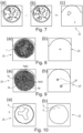
- the Figure 7 shows the difference between two images, whereby one image was created with polarized light, and by the difference a corresponding area 5, which is formed as a reflective glue spot, can be detected.
- Figure 8 shows on the left a black and white image 20 of a front surface 3 and on the right the difference image 23, whereby according to the invention a picture was created with polarized light.
- the rod-shaped article 1 has a tobacco rod made of recon foil cut into strips, with a metal wire arranged in the middle. The position of the reflective metal wire can be clearly seen on the difference image 23.
- Figure 9 shows on the left an acetate filter with two metal wires 34, which are arranged offset from each other.
- the positions of the metal wires 34 can be clearly seen on the difference image 23. If the detected position of the metal wire 34 deviates from a target value by more than a tolerance range Tb, this article 1 is ejected by an ejection unit.
- the tolerance range Tb can optionally be broken down into two orthogonal components TbR1 and TbR2.
- Figure 10 shows a hollow filter that is wrapped in aluminum-laminated paper.
- the small glue spots 5 and the edge areas of the aluminum-laminated wrapping paper are clearly visible.
Landscapes
- Health & Medical Sciences (AREA)
- General Health & Medical Sciences (AREA)
- Toxicology (AREA)
- Physics & Mathematics (AREA)
- Life Sciences & Earth Sciences (AREA)
- Chemical & Material Sciences (AREA)
- Analytical Chemistry (AREA)
- Biochemistry (AREA)
- General Physics & Mathematics (AREA)
- Immunology (AREA)
- Pathology (AREA)
- Investigating Materials By The Use Of Optical Means Adapted For Particular Applications (AREA)
- Investigating Or Analysing Materials By Optical Means (AREA)
Description
- Die vorliegende Erfindung betrifft ein Verfahren und eine Messanordnung zum Prüfen einer Stirnfläche eines stabförmigen Artikels der tabakverarbeitenden Industrie mit einer Bereitstellungsvorrichtung für stabförmige Artikel, einer Fördervorrichtung mit mindestens einer Aufnahme für stabförmige Artikel, einer Beleuchtungseinrichtung zum Beleuchten einer Oberfläche eines stabförmigen Artikels, einer Kamera, eingerichtet und angeordnet zur Aufnahme von einer Oberfläche des stabförmigen Artikels, und einer Polarisationseinrichtung.
- Zur Qualitätsüberwachung stabförmiger Produkte der tabakverarbeitenden Industrie sind im Bereich der Herstellmaschinen optische Messverfahren bekannt. In einigen Fällen besteht das zu vermessende Produkt oder der zu vermessende stabförmige Artikel aus unterschiedlichen Materialien, welche bevorzugt unabhängig voneinander zu prüfen sind. Hierfür ist eine messtechnische Trennung der Materialien erforderlich, wobei die Materialien bevorzugt über die Helligkeit in den Bildaufnahmen detektierbar sind. Insbesondere bei glänzenden Materialien, beispielsweise einer Leimspur, einem Metallteil, glänzendem Kunststoff oder anderen glänzenden Materialien, ist eine messtechnische Trennung des Materials von einem hellen Hintergrund, beispielsweise weißem Papier oder weißem Celluloseacetat, fehlerhaft. In einer Bildaufnahme, die bevorzugt unter Verwendung eines hellen Blitzlichts erzeugt wurde, sind sowohl das Grundmaterial, beispielsweise Celluloseacetat oder weißes Papier, als auch das glänzende Material in ähnlicher Helligkeit abgebildet.
- In der
EP2677273 ist eine Vorrichtung zur dreidimensionalen Vermessung und Analyse der Tiefeninformation einer Stirnfläche eines stabförmigen Artikels der tabakverarbeitenden Industrie offenbart, die zusätzlich ein Farb-/Graustufen-/Schwarz-Weiß-Bild der Stirnfläche aufnimmt, um Qualitätsinformation zu erhalten, die nicht in der Tiefeninformation enthalten ist, wie beispielsweise Verfärbungen, (Bild-)Muster oder farbige Elemente. Eine dort offenbarte Vorrichtung weist die aufgeführten Nachteile zur messtechnischen Trennung glänzender Materialen zu einem weißen oder hellen Hintergrund auf. -
EP 2 952 878 A1 ,EP 2 677 273 A1 ,DE 698 38 174 T2 undEP 1 498 723 A1 offenbaren verschiedene Messanordnungen und Verfahren zur optischen Prüfung von Artikeln der tabakverarbeitenden Industrie. - Aufgabe der vorliegenden Erfindung ist das Bereitstellen eines Verfahrens zum Prüfen einer Oberfläche und einer Messanordnung, das bzw. die eine zuverlässige messtechnische Trennung von glänzenden Materialien auf weißem oder hellem Hintergrund gewährleistet.
- Die Aufgabe wird gelöst durch ein Verfahren nach dem vorliegenden Anspruch 1, umfassend u.a. folgende Schritte: Bereitstellen eines stabförmigen Artikels, Fördern des stabförmigen Artikels entlang eines Förderwegs, Beleuchten einer Oberfläche, insbesondere einer Stirnfläche oder einem Abschnitt einer Mantelfläche, eines stabförmigen Artikels durch eine Beleuchtungseinrichtung, bevorzugt eine LED-Beleuchtung oder eine Laser-Beleuchtung aufweisend, insbesondere zeitweise beleuchtend, bevorzugt für eine Dauer zwischen 1 µs bis 100 µs, und besonders bevorzugt in regelmäßig aufeinander folgenden Abständen, Erstellen einer Aufnahme, durch eine Kamera, bevorzugt eine Schwarz-Weiß-Kamera, von der Oberfläche des stabförmigen Artikels, wobei das durch die Beleuchtungseinrichtung ausgestrahlte und von der Oberfläche reflektierte Licht in der Kamera detektiert wird und einen Strahlenpfad bildet, wobei das Licht auf dem Strahlenpfad durch eine Polarisationseinrichtung, angeordnet in oder benachbart zu der Beleuchtungseinrichtung und/oder als Polarisationsfilter und/oder als polarisierender Strahlenteiler ausgebildet, polarisiert wird, insbesondere linear, bevorzugt mit einem Polarisationsgrad von größer 0,5 oder 0,7 oder 0,9 oder 0,98, dadurch gekennzeichnet, dass mindestens zwei Polarisationseinrichtungen benachbart zueinander, insbesondere entlang des Strahlenpfades stromabwärts der Oberfläche, angeordnet sind, wobei sich die Polarisationswinkel der Polarisationseinrichtungen unterscheiden, insbesondere um 90° oder 45° versetzt sind, und/oder dass mindestens zwei Aufnahmen, durch die Kamera, bevorzugt eine Schwarz-Weiß-Kamera, von der, insbesondere derselben oder im Wesentlichen derselben, Oberfläche des stabförmigen Artikels erstellt werden, wobei das durch die Beleuchtungseinrichtung ausgestrahlte und von der Oberfläche reflektierte Licht in der Kamera detektiert wird, insbesondere beide Aufnahmen auf einem Kamerachip, bevorzugt gleichzeitig, aufgenommen werden, und wobei insbesondere das in die Kamera einfallende Licht zur Erstellung der beiden Aufnahmen bevorzugt jeweils durch eine Polarisationseinrichtung polarisiert wird, wobei sich die Polarisationswinkel der Polarisationseinrichtungen unterscheiden, insbesondere um 90° oder 45° versetzt sind. Durch die Verwendung von polarisiertem Licht oder durch die Erstellung von mehreren Bildaufnahmen, wobei mindestens eine Bildaufnahme oder mindestens zwei Bildaufnahmen mit polarisiertem Licht erstellt wurde bzw. wurden, sind zuverlässig glänzende Bereiche auf der Oberfläche eines stabförmigen Artikels detektierbar.
- Eine bevorzugte Ausführungsform des Verfahrens ist dadurch gekennzeichnet, dass ein Polarisationsfilter und/oder ein polarisierender Strahlenteiler zwischen Beleuchtungseinrichtung und Oberfläche und/oder zwischen Oberfläche und Kamera angeordnet ist oder sind. Eine Polarisationseinrichtung ist an einer beliebigen Stelle auf dem Strahlenpfad anzuordnen, bevorzugt im ersten Drittel, im zweiten Drittel oder im dritten Drittel des Strahlenpfads, oder bevorzugt im Bereich von ±20 % der Länge des Strahlenpfads der Mitte. Wahlweise ist sowohl das auf die zu vermessende Oberfläche fallende Licht als auch das von der Kamera detektierte Licht durch eine Polarisationseinrichtung zu polarisieren.
- Eine bevorzugte Ausführungsform des Verfahrens ist dadurch gekennzeichnet, dass mindestens zwei Aufnahmen von der, bevorzugt derselben oder im Wesentlichen derselben, Oberfläche, insbesondere gleichzeitig, erstellt werden und mindestens eine Aufnahme mit polarisiertem Licht erstellt wird, und die Unterschiede der mindestens zwei Aufnahmen ausgewertet werden, insbesondere eine Differenz oder ein Quotient der beiden Aufnahmen gebildet und bevorzugt das Differenz- bzw. Quotientenbild ausgewertet wird. Durch die Betrachtung und Auswertung der Unterschiede der beiden Aufnahmen, insbesondere durch die Auswertung eines Differenzbildes, ist die messtechnische Trennung von glänzenden Materialien auf weißem oder hellem Hintergrund zuverlässig möglich. Neben dem Unterdrücken von Spiegelungen und Reflexionen durch eine Polarisationseinrichtung ist durch die Differenzbildung von zwei Aufnahmen die Erkennung von den entsprechenden Bereichen mit erhöhter Zuverlässigkeit möglich, da somit die Wirkung der mindestens einen Polarisationseinrichtung gezielt auswertbar ist.
- Eine bevorzugte Ausführungsform des Verfahrens ist dadurch gekennzeichnet, dass eine Aufnahme ohne polarisiertes Licht erstellt und eine weitere Aufnahme mit polarisiertem Licht erstellt wird oder dass zwei Aufnahmen mit unterschiedlich polarisiertem Licht erstellt werden.
- Eine bevorzugte Ausführungsform des Verfahrens ist dadurch gekennzeichnet, dass eine Polarisationseinrichtung zwischen Beleuchtungseinrichtung und Oberfläche des Artikels und eine zweite Polarisationseinrichtung zwischen Oberfläche des Artikels und einer Kamera angeordnet ist, wobei die Polarisationswinkel der beiden Polarisationseinrichtungen aufeinander abgestimmt sind, insbesondere die gleiche oder sich durch eine vorgebbare Winkelstellung unterscheidende Polarisationswinkel aufweisen. Durch die Abstimmung der Polarisationseinrichtungen sowohl auf die zu vermessende Oberfläche als auch untereinander sind die entsprechenden optischen Effekte, insbesondere die Spiegelungen und Glanzerscheinungen, entsprechend beeinflussbar. Hierdurch lässt sich eine vorteilhafte messtechnische Trennung der unterschiedlichen Materialien umsetzen.
- Eine bevorzugte Ausführungsform des Verfahrens ist dadurch gekennzeichnet, dass die stabförmigen Artikel nach dem Bereitstellen und vor dem Prüfen der Oberfläche ausgerichtet werden, insbesondere durch Rotation in eine vordefinierte Winkelstellung gedreht werden. Ist vor das messtechnische Prüfen eine Ausrichteinheit vorgeschaltet, um die stabförmigen Artikel in eine vordefinierte Position auszurichten, insbesondere in eine vordefinierte Position zu verdrehen, können bei der Auswertung der Aufnahmen vordefinierte Bereiche gezielt untersucht, analysiert und detektiert werden. Die Ausrichteinheit weist bevorzugt eine Magnetisierungseinrichtung auf und ist insbesondere gemäß einer der in der
EP 3 461 352 A1 offenbarten Ausführungsformen ausgebildet. - Eine bevorzugte Ausführungsform des Verfahrens ist dadurch gekennzeichnet, dass es sich bei der Oberfläche um eine Stirnfläche des stabförmigen Artikels handelt und basierend auf einer Bildauswertung Bereiche identifiziert werden, in denen der gerichtet reflektierte Anteil größer als der diffus reflektierte Anteil des auf diese Bereiche fallenden Lichts ist, um insbesondere die Lage und/oder die Ausrichtung der Bereiche in Bezug auf den Umfang und/oder das Zentrum der Stirnfläche zu bestimmen und/oder mit einem Sollwert zu vergleichen. Mit dieser vorteilhaften Ausgestaltung des Verfahrens sind Bereiche, die unterschiedlichen Materialien zugeordnet werden können, auswertbar, lokalisierbar und auf ihre richtige Anordnung innerhalb des stabförmigen Produktes oder innerhalb der Stirnfläche des stabförmigen Produktes detektier- und prüfbar.
- Eine bevorzugte Ausführungsform des Verfahrens ist dadurch gekennzeichnet, dass der stabförmige Artikel ausgeschleust wird, sofern die Lage und/oder Ausrichtung der Bereiche in Bezug auf den Umfang und/oder des Zentrums der Stirnfläche von einem Sollwert um mehr als einen Toleranzbereich Tb abweicht, wobei der Toleranzbereich Tb bevorzugt in zwei orthogonale Komponenten zerlegt ist, sodass die Lage, die Abweichung der Lage und/oder Ausrichtung vom Sollwert nicht größer als TbR1 in Richtung R1 und/oder nicht größer als TbR2 in Richtung R2 ist, insbesondere der Toleranzbereich Tb, TbR1 und/oder TbR2 maximal ±2 mm, ±1 mm oder ±0,5 mm beträgt.
- Die Aufgabe wird ebenfalls durch eine Messanordnung nach Anspruch 9 gelöst mit einer Bereitstellungsvorrichtung für stabförmige Artikel, einer Fördervorrichtung mit mindestens einer Aufnahme für stabförmige Artikel, einer Beleuchtungseinrichtung zum Beleuchten einer Oberfläche, insbesondere einer Stirnfläche oder einem Abschnitt der Mantelfläche, eines stabförmigen Artikels, insbesondere eingerichtet um eine zeitweise, bevorzugt für eine Dauer zwischen 1 µs bis 100 µs, und besonders bevorzugt in regelmäßigen Abständen aufeinander folgende Beleuchtung zu erzeugen, einer Kamera, bevorzugt Schwarz-Weiß-Kamera, eingerichtet und angeordnet zur Aufnahme von der Oberfläche des stabförmigen Artikels, wobei das durch die Beleuchtungseinrichtung ausgestrahlte und von der Oberfläche reflektierte Licht von der Kamera detektierbar ist, und einer Polarisationseinrichtung, die bevorzugt innerhalb oder benachbart zu der Beleuchtungseinrichtung angeordnet, als Polarisationsfilter und/oder durch einen polarisierenden Strahlenteiler ausgebildet ist, wobei insbesondere eine Schutzvorrichtung, die bevorzugt als optisch durchsichtige Scheibe ausgebildet ist, und insbesondere eine Einheit zum Sauberblasen der Schutzvorrichtung vorgesehen ist, dadurch gekennzeichnet, dass die Polarisationseinrichtung zwischen Aufnahme der Fördervorrichtung und der Kamera angeordnet ist sowie ausgebildet und eingerichtet ist, linear polarisiertes Licht mit einem Polarisationsgrad von größer 0,5 oder 0,7 oder 0,9 oder 0,98 zu erzeugen, und/oder dass die Messanordnung mindestens zwei Polarisationseinrichtungen aufweist, wobei insbesondere sich die Polarisationswinkel der Polarisationseinrichtungen unterscheiden, insbesondere um 90° oder 45° versetzt sind.
- Um Wiederholungen zu vermeiden gelten die Vorteile für das Messverfahren analog für die entsprechenden Messanordnungen.
- Eine bevorzugte Ausführungsform der Messanordnung ist dadurch gekennzeichnet, dass ein Polarisationsfilter und/oder ein polarisierender Strahlenteiler zwischen Beleuchtungseinrichtung und Aufnahme der Fördervorrichtung und/oder zwischen Aufnahme der Fördervorrichtung und Kamera angeordnet ist oder sind.
- Eine bevorzugte Ausführungsform der Messanordnung ist dadurch gekennzeichnet, dass die Kamera eingerichtet ist mindestens zwei Aufnahmen von derselben Oberfläche, insbesondere gleichzeitig, zu erstellen, wobei mindestens eine Aufnahme mit polarisiertem Licht erstellt wird, und bevorzugt die Unterschiede der mindestens zwei Aufnahmen ausgewertet werden, insbesondere eine Differenz oder ein Quotient der beiden Aufnahmen erstellt und bevorzugt das Differenz- bzw. Qotientenbild ausgewertet wird.
- Die Messanordnung ist dadurch gekennzeichnet, dass die Messanordnung eingerichtet ist, eine Aufnahme ohne polarisiertes Licht und eine weitere Aufnahme mit polarisiertem Licht zu erstellen, oder dass zwei Polarisationseinrichtungen vorgesehen sind, um zwei Aufnahmen mit unterschiedlich polarisiertem Licht zu erstellen, wobei die Polarisationseinrichtungen unterschiedliche Polarisationswinkel aufweisen, welche insbesondere um 90° oder 45° versetzt sind.
- Eine bevorzugte Ausführungsform der Messanordnung ist dadurch gekennzeichnet, dass eine Polarisationseinrichtung zwischen Beleuchtungseinrichtung und Aufnahme des stabförmigen Artikels und eine zweite Polarisationseinrichtung zwischen Aufnahme des stabförmigen Artikels und einer Kamera angeordnet ist, wobei die Polarisationswinkel der beiden Polarisationseinrichtungen aufeinander abgestimmt sind, insbesondere die gleiche oder eine durch eine vorgebbare Winkellage unterschiedliche Polarisationswinkel aufweisen.
- Eine bevorzugte Ausführungsform der Messanordnung ist dadurch gekennzeichnet, dass zwischen Bereitstellungsvorrichtung und Kamera eine Ausrichteinheit angeordnet ist, die insbesondere ausgebildet und eingerichtet ist die stabförmigen Artikel durch Rotation in eine vordefinierte Winkelstellung zu drehen. Die Ausrichteinheit weist bevorzugt eine Magnetisierungseinrichtung auf.
- Eine bevorzugte Ausführungsform der Messanordnung ist dadurch gekennzeichnet, dass die Kamera eingerichtet ist, eine Stirnfläche des stabförmigen Artikels aufzunehmen, und eine Auswerteeinheit vorgesehen ist, die basierend auf einer Bildauswertung Bereiche identifiziert, in denen der gerichtet reflektierte Anteil größer als der diffus reflektierte Anteil des auf diese Bereiche fallenden Lichts ist, um insbesondere die Lage, die Abweichung der Lage und/oder die Ausrichtung der Bereiche in Bezug auf den Umfang und/oder das Zentrum der Stirnfläche des Artikels zu bestimmen oder mit einem Sollwert zu vergleichen.
- Eine bevorzugte Ausführungsform der Messanordnung ist dadurch gekennzeichnet, dass eine Ausschleuseinheit vorgesehen ist, die bevorzugt stromabwärts der Kamera angeordnet ist, und der stabförmige Artikel ausgeschleust wird, sofern die Lage, die Abweichung von der Lage und/oder Ausrichtung der Bereiche in Bezug auf den Umfang und/oder das Zentrum der Stirnfläche des Artikels von einem Sollwert um mehr als einen Toleranzbereich Tb abweicht, wobei bevorzugt der Toleranzbereich Tb in zwei orthogonale Komponenten zerlegt ist, sodass die Lage, die Abweichung er Lage und/oder Ausrichtung vom Sollwert durch TbR1 in Richtung R1 und/oder durch TbRo2 in Richtung R2 begrenzt ist, wobei insbesondere der Toleranzbereich Tb, TbR1 und/oder TbR2 maximal ±2 mm, ±1 mm oder ±0,5 mm beträgt.
- Bevorzugt sind in jeder offenbarten und beanspruchten Ausführungsform der Messanordnung und des Verfahrens stromaufwärts der Kamera eine Strangeinheit zum Herstellen eines Stranges und/oder eine Schneideinheit zum Schneiden des Stranges in stabförmige Artikel oder zum Schneiden von mehrfach langen stabförmigen Artikeln in stabförmige Artikel beliebiger Länge.
- Unter einer Schwarz-Weiß-Kamera ist eine Kamera zu verstehen, die ein Graustufenbild erzeugt. Alternativ oder zusätzlich, bei der Verwendung von mehreren Kameras, ist wahlweise eine Farbkamera zu verwenden. Die in diesen Unterlagen offenbarten Kameras weisen bevorzugt einen Kamerachip oder mehrere Kamerachips auf, bevorzugt zwei, drei oder vier Kamerachips.
- Die Erfindung wird weiter im Hinblick auf beispielhafte Ausführungsformen beschrieben, die anhand der folgenden Zeichnungen veranschaulicht werden, in denen:
-
Fig. 1 zeigt schematisch eine Stirnfläche eines stabförmigen Artikels; -
Fig. 2 zeigt schematisch einen Bereich der Mantelfläche eines stabförmigen Artikels; -
Fig. 3, 4 und6 zeigen Ausführungsformen einer Messvorrichtung; -
Fig. 5 zeigt einen Kamerachip mit Polarisationsfiltern und -
Fig. 7 bis 10 zeigen Aufnahmen und ausgewertete Aufnahmen einer Stirnfläche eines stabförmigen Artikels. -
Figur 1 zeigt eine Stirnfläche 3 eines stabförmigen Artikels 1 der tabakverarbeitenden Industrie, welche verschiedene Materialien aufweist. Der Umfang 6 der Stirnfläche ist im Wesentlichen kreisrund und durch ein Umhüllungspapier gebildet. Auf der Stirnfläche sind Bereiche 5, die glänzende Eigenschaften aufweisen. Hierbei kann es sich beispielsweise um Metallteile, Leimflecken oder um glänzenden Kunststoff handeln. - In
Figur 2 ist ein Bereich einer Mantelfläche 4 eines stabförmigen Artikels 1 gezeigt, der ebenfalls einen Bereich 5 aufweist, der glänzende Eigenschaften besitzt. Die Bereiche 5 besitzen glänzende Eigenschaften und sind bevorzugt dadurch gekennzeichnet, dass in den Bereichen der gerichtet reflektierte Anteil größer als der diffus reflektierte Anteil des auf diese Bereiche fallenden Lichts ist. - Eine Vorrichtung zum optischen Prüfen einer Stirnfläche 3 eines stabförmigen Artikels 1 der tabakverarbeitenden Industrie ist in Figur 3 gezeigt. Die Vorrichtung weist eine Beleuchtungseinrichtung 11 auf, die als Ring mit einer mittigen Öffnung ausgebildet ist und wobei auf dem Ring Leuchteinheiten, insbesondere eine LED-Beleuchtung angeordnet sind. Die Beleuchtungseinrichtung kann wahlweise einzelne Leuchtmittel aufweisen und nicht als Ring ausgebildet sein, beispielsweise in Form eines "C" oder als einzelne punktförmige Leuchtmittel. Der Strahlenpfad 33 ausgehend von der Beleuchtungseinrichtung 11 über die Oberfläche 2 zur Kamera 10, insbesondere bis zum Pixel-Array 31 ist in
Figur 3, 4 und6 gezeigt. Zwischen der Beleuchtungseinrichtung 11 und der Stirnfläche 3 des stabförmigen Artikels 1 sind die Polarisationseinrichtungen 12.1, 12.2, welche als Polarisationsfilter ausgebildet sind, und eine Schutzvorrichtung 30, die als optisch durchsichtige Scheibe ausgebildet ist, um die Messvorrichtung vor Staubpartikel und/oder Verschmutzung zu schützen, vorgesehen. Eine inFigur 3 nicht gezeigte Einheit zum Sauberblasen der Schutzvorrichtung 30 stellt einen wahlweisen Bestandteil jeder Ausführungsform dar und ist unabhängig von jeder offenbarten oder beanspruchten Ausführungsform. Die Vorrichtung umfasst eine Kamera 10, die einen Kamerachip 13 aufweist sowie ein halbreflektierendes optisches Element 14, ein totalreflektierende optisches Element 15 und zwei Polarisationseinrichtungen 12.3, 12.4, die als Polarisationsfilter ausgebildet sind. Das von der Beleuchtungseinrichtung 11 ausgestrahlte Licht ist durch die Polarisationseinrichtungen 12.1 und 12.2, bevorzugt linear, polarisiert, insbesondere mit dem gleichen Polarisationswinkel. Das von der Stirnfläche 3 des stabförmigen Artikels 1 reflektierte Licht trifft auf das halbreflektierende optisches Element 14, welches als halbreflektierende Spiegel oder halbreflektierende Prisma ausgebildet ist, und ein Teil des Lichts wird auf den Kamerachip 13 weitergeleitet, welches zuvor durch die Polarisationseinrichtung 12.3, welche bevorzugt als Polarisationsfilter ausgebildet ist, polarisiert wird. Der andere Teil des Lichts wird von dem halbreflektierenden optischen Element 14 auf das totalreflektierende optische Element 15 weitergeleitet, welches bevorzugt als Spiegel ausgebildet ist, und durch die Polarisationseinrichtung 12.4, welche als Polarisationsfilter ausgebildet ist, polarisiert und auf einen anderen Bereich des Kamerachips 13 treffend geleitet. Auf dem Kamerachip 13 entstehen zwei separate Bilder der gleichen Stirnfläche 3, welche jeweils durch Licht mit einem Polarisationswinkel basierend auf den Polarisationseinrichtungen 12.3 beziehungsweise 12.4 aufweisen. Die Polarisationseinrichtungen 12.1 bis 12.4 sind bevorzugt aufeinander abgestimmt. Weisen die Polarisationseinrichtungen 12.1 und 12.2 beispielsweise einen horizontalen Polarisationswinkel auf, weist der Polarisationseinrichtung 12.3 bevorzugt ebenfalls einen horizontalen Polarisationswinkel auf und die Polarisationseinrichtung 12.4 bevorzugt einen vertikalen Polarisationswinkel auf. Die Ausrichtung der Polarisationseinrichtungen 12.1 bis 12.4 sind beliebig wählbar und aufeinander anpassbar. Bevorzugt weist mindestens eine der Polarisationseinrichtungen 12.1 und 12.2 den gleichen Polarisationswinkel auf wie eine der Polarisationseinrichtungen 12.3 und 12.4. Bei der Ausführungsform nachFigur 3 ist eine nicht dargestellte Auswerteeinheit vorgesehen, die ein Differenzbild der durch den Kamerachip 13 aufgenommenen separaten Bilder erstellt und auswertet. Die Aufnahmen werden bevorzugt zueinander ausgerichtet und bevorzugt eine Differenzbild 23 erzeugt. Dieses Differenzbild 23 zeigt entsprechende Bereiche 5, die ein glänzendes Material aufweisen. Dieses Verfahren ist analog auf die Bildung von Qotientenbildern anwendbar oder auf eine andersartige Auswertung der Unterschiede von zwei Aufnahmen. - Die in
Figur 4 gezeigte Vorrichtung ist eine Abwandlung der inFigur 3 gezeigten Vorrichtung. Um Wiederholungen zu vermeiden sind nachfolgend lediglich die Abwandlungen der Vorrichtung ausFigur 3 beschrieben. Hierbei entspricht die Polarisationseinrichtung 12.6 ausFigur 4 der Polarisationseinrichtung 12.4 ausFigur 3 . Der wesentliche Unterschied der beiden Vorrichtungen ist gekennzeichnet, durch das Weglassen der Polarisationseinrichtungen 12.3, sodass das ein Teil des von der Stirnfläche 3 reflektierten Lichts direkt auf den Kamerachip 13 fällt ohne eine Polarisationseinrichtung zu passieren. In einer Abwandlung ist das halbreflektierende optische Element 14 als ein polarisierender Strahlenteiler 35 ausgebildet, sodass zwei Aufnahmen mit polarisiertem Licht erstellt werden. - Wahlweise enthalten die in
Figur 3 oder Figur 4 gezeigten Ausführungsformen anstatt einem Kamerachip 13 zwei, drei oder mehr als drei Kamerachips 13. Bevorzugt werden die beiden Bilder mit Licht, die unterschiedliche Polarisationswinkel aufweisen, auf zwei separaten Kamerachips 13 aufgenommen. Wahlweise sind anstatt mehrerer Kamerachips 13 mehr als eine, zwei oder mehr als drei Kameras 10 zu verwenden. - In
Figur 5 ist ein Kamerachip 13 einer Polarisationskamera gezeigt, der drei Ebenen aufweist. Der Kamerachip 13 ist als matrixartige Anordnung aus Pixeln 16 ausgebildet, die einen Pixel-Array 31 bilden. Die zweite Ebene weist Polarisationseinrichtungen 12 auf, wobei jedem Pixel 16 ein Polarisationsfilter 12.7 bis 12.10 zugeordnet ist. Die Polarisationsfilter 12.7 bis 12.10 weisen jeweils vier unterschiedliche Polarisationswinkel auf, welche horizontal und vertikal sowie diagonal gemäß der Polarisationseinrichtungen 12.7 bis 12.10 ausgebildet sind. Der Kamerachip 13 ist somit in Pixelgruppen bestehend aus vier Pixeln 16 unterteilt, wobei jedem Pixel 16 eine unterschiedliche Polarisationseinrichtung 12.7 bis 12.10 zugeordnet ist. Dieses Vorgehen ist von handelsüblichen Farbkameras bekannt, wobei jedem Pixel 16 der entsprechenden Pixelgruppe analog eine Grundfarbe zugeordnet ist. Die dritte Ebene weist einen Linsen-Array 18 auf, wobei jedem Pixel 16 eine separate Linse 17 zugeordnet ist. Durch einen derartigen Kamerachip 13 sind mit einem Kamerachip vier Aufnahmen derselben Oberfläche gleichzeitig möglich, wobei jedes Bild durch Licht mit einem anderen Polarisationswinkel entsteht. Diese Ausgestaltung der Vorrichtung ermöglicht eine kompakte und kostengünstige Bauweise einer Polarisationskamera für den entsprechenden Anwendungsfall. Eine Abwandlung des Kamerachips 13 ist durch eine Abwandlung der Polarisationsfilter 12.7 bis 12.10 ausgebildet. Beispielsweise kann der Polarisationsfilter 12.7 entfernt werden, sodass ein Bild durch den Kamerachip 13 aufgenommen wird, welches nicht zuvor durch einen Polarisationsfilter im Polarisationsfilter-Array 32 polarisiert wurde. Eine Abwandlung des inFigur 5 und Figur 6 gezeigten Kamerachips 13 ist zur Aufnahme von Farbbildern ausgebildet. Wobei jeweils ein Pixel 16 zur Erfassung für jede der drei Grundfarben und ein weiterer Pixel zur Erfassung der Graustufen oder einer der drei Grundfarben ausgebildet ist. Bei der Verwendung eines Polarisationsfilter-Arrays 32 mit vier unterschiedlichen Polarisationsfiltern 12.7 bis 12.10 ergeben sich anstatt der vier Pixeln 16 für eine Schwarz-Weiß-Aufnahme sechszehn Pixel 16 für eine Farbaufnahme. Ist der Polarisationsfilter Array 32 lediglich mit Polarisationsfiltern 12.9 und 12.10 oder 12.7 und 12.8 versehen, weist der Kamerachip 13 für Farbaufnahmen lediglich Pixelgruppen von acht Pixeln 16 und bei Schwarz-Weiß-Aufnahmen lediglich Pixelgruppen von zwei Pixeln 16 auf. - In
Figur 6 ist der Kamerachip 13 bestehend aus den drei Ebenen, Pixel-Array 31, Polarisationsfilter-Array 32 und Linsen-Array 18, in die inFigur 3 gezeigte Vorrichtung integriert. Das von der Stirnfläche 3 reflektierte und zuvor von den Polarisationseinrichtungen 12.1 und 12.2 polarisierte Licht fällt von der Stirnfläche 3 wahlweise durch die Schutzvorrichtung 30 direkt in die Polarisationskamera, durchdringt den Linsen-Array 18, wird durch den Polarisationsfilter-Array 32 polarisiert und trifft auf den Pixel-Array 31. Die vier so entstandenen Bilder werden durch die Auswerteeinheit ausgewertet und es können beliebige Differenzbilder generiert werden. - Die
Figur 7 zeigt die Differenzbildung zweier Aufnahmen, wobei eine Aufnahme mit polarisiertem Licht entstanden ist, und durch die Differenzbildung ein entsprechender Bereich 5, welcher als reflektierender Leimfleck ausgebildet ist, detektierbar ist.Figur 8 zeigt links eine Schwarz-Weiß-Aufnahme 20 einer Stirnfläche 3 und rechts das Differenzbild 23 wobei erfindungsgemäß eine Aufnahme mit polarisiertem Licht entstanden ist. Der stabförmige Artikel 1 weist einen Tabakstock aus in Streifen geschnittener Rekonfolie auf, wobei mittig ein Metalldraht angeordnet ist. Auf dem Differenzbild 23 ist die Position des reflektierenden Metalldrahts klar und deutlich zu erkennen. -
Figur 9 zeigt links einen Acetatfilter mit zwei Metalldrähten 34, welche versetzt zueinander angeordnet sind. Auf dem Differenzbild 23 sind die Positionen der Metalldrähte 34 deutlich zu erkennen. Weicht die detektierte Lage des Metalldrahtes 34 von einem Sollwert um mehr als einen Toleranzbereich Tb ab, wird dieser Artikel 1 durch eine Ausschleuseinheit ausgeschleust. Der Toleranzbereich Tb ist wahlweise in zwei orthogonale Komponenten TbR1 und TbR2 zerlegbar. -
Figur 10 zeigt einen Hohlfilter, der mit aluminiumkaschiertem Papier umwickelt ist. Auf der Stirnfläche 3 des Hohlfilters befinden sich kleine Leimflecken 5, welche auf dem herkömmlichen Schwarz-Weiß-Bild 20 kaum zu erkennen sind. Auf dem Differenzbild 23 sind die kleinen Leimflecken 5 und die Randbereiche des mit aluminiumkaschierten Umhüllungspapiers deutlich zu erkennen.
Claims (15)
- Verfahren zum Prüfen einer Oberfläche (2), nämlich einer Stirnfläche (3), eines stabförmigen Artikels (1) der tabakverarbeitenden Industrie, umfassend folgende Schritte:- Bereitstellen eines stabförmigen Artikels (1),- Fördern eines stabförmigen Artikels (1) entlang eines Förderwegs,- Beleuchten einer Oberfläche (2), nämlich der Stirnfläche (3), des stabförmigen Artikels (1) durch eine Beleuchtungseinrichtung (11),- Erstellen einer Aufnahme durch eine Kamera (10) von der Oberfläche (2) des stabförmigen Artikels (1), wobei das durch die Beleuchtungseinrichtung ausgestrahlte und von der Oberfläche (2) reflektierte Licht in der Kamera (10) detektiert wird und einen Strahlenpfad (33) bildet,- wobei das Licht auf dem Strahlenpfad (33) durch eine Polarisationseinrichtung (12) polarisiert wird,dadurch gekennzeichnet, dassmindestens zwei Polarisationseinrichtungen (12) benachbart zueinander angeordnet sind, wobei sich die Polarisationswinkel der Polarisationseinrichtungen (12) unterscheiden,
und/oderdass mindestens zwei Aufnahmen (20 bis 22) durch eine Kamera (10) von der Oberfläche des stabförmigen Artikels (1) erstellt werden, wobei das durch die Beleuchtungseinrichtung (11) ausgestrahlte und von der Oberfläche (2) reflektierte Licht in der Kamera (10) detektiert wird. - Verfahren nach Anspruch 1, dadurch gekennzeichnet, dass ein Polarisationsfilter (12.1 bis 12.10) und/oder ein polarisierender Strahlenteiler (35) zwischen Beleuchtungseinrichtung (11) und Oberfläche (2) und/oder zwischen Oberfläche (2) und Kamera (10) angeordnet ist oder sind.
- Verfahren nach einem der Ansprüche 1 und 2, dadurch gekennzeichnet, dass mindestens zwei Aufnahmen (20 bis 22) von der Oberfläche (2) erstellt werden und mindestens eine Aufnahme (20 bis 22) mit polarisiertem Licht erstellt wird, und die Unterschiede der mindestens zwei Aufnahmen ausgewertet werden.
- Verfahren nach einem der Ansprüche 1 bis 3, dadurch gekennzeichnet, dass eine Aufnahme (20 bis 22) ohne polarisiertes Licht erstellt und eine weitere Aufnahme (20 bis 22) mit polarisiertem Licht erstellt wird oder dass zwei Aufnahmen (20 bis 22) mit unterschiedlich polarisiertem Licht erstellt werden.
- Verfahren nach einem der Ansprüche 1 bis 4, dadurch gekennzeichnet, dass eine Polarisationseinrichtung (12) zwischen Beleuchtungseinrichtung (11) und Oberfläche (2) des Artikels (1) und eine zweite Polarisationseinrichtung (12) zwischen Oberfläche (2) des Artikels (1) und einer Kamera (10) angeordnet ist, wobei die Polarisationswinkel der beiden Polarisationseinrichtungen (12) aufeinander abgestimmt sind.
- Verfahren nach einem der Ansprüche 1 bis 5, dadurch gekennzeichnet, dass die stabförmigen Artikel (1) nach dem Bereitstellen und vor dem Prüfen der Oberfläche (2) ausgerichtet werden.
- Verfahren nach einem der Ansprüche 1 bis 6, dadurch gekennzeichnet, dass basierend auf einer Bildauswertung Bereiche (5) identifiziert werden, in denen der gerichtet reflektierte Anteil größer als der diffus reflektierte Anteil des auf diese Bereiche (5) fallenden Lichts ist.
- Verfahren nach Anspruch 7, dadurch gekennzeichnet, dass der stabförmige Artikel (1) ausgeschleust wird, sofern die Lage und/oder Ausrichtung der Bereiche (5) in Bezug auf den Umfang und/oder des Zentrums der Stirnfläche (3) von einem Sollwert um mehr als einen Toleranzbereich (Tb) abweicht.
- Messanordnung zum Prüfen einer Oberfläche (2), nämlich einer Stirnfläche (3), eines stabförmigen Artikels (1) der tabakverarbeitenden Industrie mit einer Bereitstellungsvorrichtung für stabförmige Artikel (1),einer Fördervorrichtung mit mindestens einer Aufnahme für stabförmige Artikel (1),einer Beleuchtungseinrichtung (11) zum Beleuchten einer Oberfläche (2), nämlich einer Stirnfläche (3), eines stabförmigen Artikels (1),einer Kamera (10) eingerichtet und angeordnet zur Aufnahme von der Oberfläche (2) des stabförmigen Artikels (1), wobei das durch die Beleuchtungseinrichtung (11) ausgestrahlte und von der Oberfläche (2) reflektierte Licht von der Kamera (10) detektierbar ist, undeiner Polarisationseinrichtung (12)dadurch gekennzeichnet, dassdie Polarisationseinrichtung (12) ausgebildet und eingerichtet ist, linear polarisiertes Licht zu erzeugen und/oder dass die Messanordnung mindestens zwei Polarisationseinrichtungen (12) aufweist, wobei sich die Polarisationswinkel der Polarisationseinrichtungen (12) unterscheiden, wobei die Messanordnung eingerichtet ist, eine Aufnahme ohne polarisiertes Licht und eine weitere Aufnahme mit polarisiertem Licht zu erstellen
oderdass zwei Polarisationseinrichtungen (12) vorgesehen sind, um zwei Aufnahmen (20 bis 22) mit unterschiedlich polarisiertem Licht zu erstellen, wobei die Polarisationseinrichtungen (12) unterschiedliche Polarisationswinkel aufweisen. - Messanordnung nach Anspruch 9, dadurch gekennzeichnet, dass ein Polarisationsfilter (12.1 bis 12.10) und/oder ein polarisierender Strahlenteiler (35) zwischen Beleuchtungseinrichtung (11) und Aufnahme der Fördervorrichtung und/oder zwischen Aufnahme der Fördervorrichtung und Kamera (10) angeordnet ist oder sind.
- Messanordnung nach einem der Ansprüche 9 und 10 dadurch gekennzeichnet, dass die Kamera (10) eingerichtet ist, mindestens zwei Aufnahmen (20 bis 22) von der Oberfläche (2) zu erstellen, wobei mindestens eine Aufnahme mit polarisiertem Licht erstellt wird.
- Messanordnung nach einem der Ansprüche 9 bis 11, dadurch gekennzeichnet, dass eine Polarisationseinrichtung (10) zwischen Beleuchtungseinrichtung (11) und Aufnahme des stabförmigen Artikels (1) und eine zweite Polarisationseinrichtung (12) zwischen Aufnahme des stabförmigen Artikels (1) und einer Kamera (10) angeordnet ist, wobei die Polarisationswinkel der beiden Polarisationseinrichtungen (12) aufeinander abgestimmt sind.
- Messanordnung nach einem der Ansprüche 9 bis 12, dadurch gekennzeichnet, dass zwischen Bereitstellungsvorrichtung und Kamera (10) eine Ausrichteinheit angeordnet ist.
- Messanordnung nach einem der Ansprüche 9 bis 13 dadurch gekennzeichnet, dass die Kamera (10) eingerichtet ist eine Stirnfläche (3) des stabförmigen Artikels (1) aufzunehmen und eine Auswerteinheit vorgesehen ist, die basierend auf einer Bildauswertung Bereiche (5) identifiziert, in denen der gerichtet reflektierte Anteil größer als der diffus reflektierte Anteil des auf diese Bereiche (5) fallenden Lichts ist.
- Messanordnung nach Anspruch 14, dadurch gekennzeichnet, dass eine Ausschleuseinheit vorgesehen ist, die zum Ausschleusen der stabförmigen Artikel (10) eingerichtet ist, sofern die Lage, die Abweichung von der Lage und/oder Ausrichtung der Bereiche (5) in Bezug auf den Umfang und/oder das Zentrum der Stirnfläche (3) des Artikels (1) von einem Sollwert um mehr als einen Toleranzbereich (Tb) abweicht.
Applications Claiming Priority (2)
| Application Number | Priority Date | Filing Date | Title |
|---|---|---|---|
| DE102020106444.6A DE102020106444A1 (de) | 2020-03-10 | 2020-03-10 | Messanordnung und Verfahren zur optischen Prüfung von Artikeln der tabakverarbeitenden Industrie |
| PCT/EP2021/055849 WO2021180681A1 (de) | 2020-03-10 | 2021-03-09 | Messanordnung und verfahren zur optischen prüfung von artikeln der tabakverarbeitenden industrie |
Publications (2)
| Publication Number | Publication Date |
|---|---|
| EP4117463A1 EP4117463A1 (de) | 2023-01-18 |
| EP4117463B1 true EP4117463B1 (de) | 2024-09-18 |
Family
ID=70470621
Family Applications (1)
| Application Number | Title | Priority Date | Filing Date |
|---|---|---|---|
| EP21711213.5A Active EP4117463B1 (de) | 2020-03-10 | 2021-03-09 | Messanordnung und verfahren zur optischen prüfung von artikeln der tabakverarbeitenden industrie |
Country Status (4)
| Country | Link |
|---|---|
| EP (1) | EP4117463B1 (de) |
| DE (1) | DE102020106444A1 (de) |
| PL (1) | PL4117463T3 (de) |
| WO (1) | WO2021180681A1 (de) |
Families Citing this family (2)
| Publication number | Priority date | Publication date | Assignee | Title |
|---|---|---|---|---|
| DE102022112419A1 (de) | 2022-05-18 | 2023-11-23 | Körber Technologies Gmbh | Anordnung zum queraxialen Fördern von stabförmigen Artikeln der Tabak verarbeitenden Industrie |
| EP4632360A1 (de) * | 2024-04-11 | 2025-10-15 | G.D S.p.A. | Verfahren zur durchführung einer optischen analyse eines produkts der tabakverabeitenden industrie und vorrichtung für die herstellung von produkten der tabakindustrie |
Citations (7)
| Publication number | Priority date | Publication date | Assignee | Title |
|---|---|---|---|---|
| EP0330495A2 (de) | 1988-02-26 | 1989-08-30 | R.J. Reynolds Tobacco Company | Verpackungsbeaufsichtigungssystem |
| EP0704172A2 (de) | 1994-09-30 | 1996-04-03 | Philip Morris Products Inc. | Verfahren und Vorrichtung zur Kontrollierung von hauptsachlich runden Gegenständen |
| WO2009132752A1 (de) | 2008-04-28 | 2009-11-05 | Focke & Co. (Gmbh & Co. Kg) | Verfahren und vorrichtung zum prüfen von mit folie umwickelten zigarettenpackungen |
| EP2677273A1 (de) | 2012-06-14 | 2013-12-25 | HAUNI Maschinenbau AG | Messvorrichtung und Verfahren zur optischen Prüfung einer Stirnfläche eines queraxial geförderten stabförmigen Produkts der Tabak verarbeitenden Industrie |
| EP1591025B1 (de) * | 2003-01-21 | 2016-04-13 | Japan Tobacco Inc. | Inspektionsvorrichtung für beschichtetes parfüm und damit ausgestattete maschine zur zigarettenherstellung |
| EP3239696A1 (de) | 2016-04-29 | 2017-11-01 | Focke & Co. (GmbH & Co. KG) | Verfahren zur prüfung von zigaretten oder zigarettenpackungen |
| WO2021121790A1 (en) | 2019-12-19 | 2021-06-24 | Philip Morris Products S.A. | Method and system for optical analysis of a component of an aerosol generating article |
Family Cites Families (4)
| Publication number | Priority date | Publication date | Assignee | Title |
|---|---|---|---|---|
| US6020969A (en) * | 1997-07-11 | 2000-02-01 | Philip Morris Incorporated | Cigarette making machine including band inspection |
| EP1498723A1 (de) * | 2003-07-17 | 2005-01-19 | Hauni Maschinbau AG | Verfahren zum Erkennen von Fremdkörpern innerhalb eines kontinuierlich geführten Produktstroms und Vorrichtung zur Durchführung desselben |
| JP6065875B2 (ja) * | 2014-06-02 | 2017-01-25 | 横河電機株式会社 | 偏光検査装置 |
| DE102017122752A1 (de) | 2017-09-29 | 2019-04-04 | Hauni Maschinenbau Gmbh | Vorrichtung zur Bearbeitung von Artikeln der Tabak verarbeitenden Industrie |
-
2020
- 2020-03-10 DE DE102020106444.6A patent/DE102020106444A1/de active Pending
-
2021
- 2021-03-09 WO PCT/EP2021/055849 patent/WO2021180681A1/de not_active Ceased
- 2021-03-09 EP EP21711213.5A patent/EP4117463B1/de active Active
- 2021-03-09 PL PL21711213.5T patent/PL4117463T3/pl unknown
Patent Citations (7)
| Publication number | Priority date | Publication date | Assignee | Title |
|---|---|---|---|---|
| EP0330495A2 (de) | 1988-02-26 | 1989-08-30 | R.J. Reynolds Tobacco Company | Verpackungsbeaufsichtigungssystem |
| EP0704172A2 (de) | 1994-09-30 | 1996-04-03 | Philip Morris Products Inc. | Verfahren und Vorrichtung zur Kontrollierung von hauptsachlich runden Gegenständen |
| EP1591025B1 (de) * | 2003-01-21 | 2016-04-13 | Japan Tobacco Inc. | Inspektionsvorrichtung für beschichtetes parfüm und damit ausgestattete maschine zur zigarettenherstellung |
| WO2009132752A1 (de) | 2008-04-28 | 2009-11-05 | Focke & Co. (Gmbh & Co. Kg) | Verfahren und vorrichtung zum prüfen von mit folie umwickelten zigarettenpackungen |
| EP2677273A1 (de) | 2012-06-14 | 2013-12-25 | HAUNI Maschinenbau AG | Messvorrichtung und Verfahren zur optischen Prüfung einer Stirnfläche eines queraxial geförderten stabförmigen Produkts der Tabak verarbeitenden Industrie |
| EP3239696A1 (de) | 2016-04-29 | 2017-11-01 | Focke & Co. (GmbH & Co. KG) | Verfahren zur prüfung von zigaretten oder zigarettenpackungen |
| WO2021121790A1 (en) | 2019-12-19 | 2021-06-24 | Philip Morris Products S.A. | Method and system for optical analysis of a component of an aerosol generating article |
Non-Patent Citations (4)
| Title |
|---|
| ANONYMOUS: "Introduction to Polarization ", EDMUND OPTICS, 25 February 2020 (2020-02-25), pages 1 - 9, XP093293109, Retrieved from the Internet <URL:https://web.archive.org/web/20200225050401/https://www.edmundoptics.com/knowledge-center/application-notes/optics/introduction-to-polarization/> [retrieved on 20250616] |
| ANONYMOUS: "Introduction to Polarization", EDMUND OPTICS, 20 February 2020 (2020-02-20), pages 1 - 6, XP093293106, Retrieved from the Internet <URL:https://www.edmundoptics.com/knowledge-center/application-notes/optics/introduction-to-polarization/> [retrieved on 20250616] |
| PASCHOTTA RUDIGER : "Laser Diodes - an encyclopedia article", RP PHOTONICS, 8 May 2006 (2006-05-08), pages 1 - 15, XP093293112, Retrieved from the Internet <URL:https://www.rp-photonics.com/laser_diodes.html> [retrieved on 20250602], DOI: 10.61835/m3d |
| PASCHOTTA RÜDIGER: "Encyclopedia of Laser Physics and Technology", RP - PHOTONICS, 8 May 2006 (2006-05-08), pages 1 - 2, XP093293114, Retrieved from the Internet <URL:https://web.archive.org/web/20060508090540/https://www.rp-photonics.com/laser_diodes.html> [retrieved on 20250616] |
Also Published As
| Publication number | Publication date |
|---|---|
| EP4117463A1 (de) | 2023-01-18 |
| WO2021180681A1 (de) | 2021-09-16 |
| PL4117463T3 (pl) | 2025-02-10 |
| DE102020106444A1 (de) | 2020-05-20 |
Similar Documents
| Publication | Publication Date | Title |
|---|---|---|
| DE2256736C3 (de) | Meßanordnung zur automatischen Prüfung der Oberflächenbeschaffenheit und Ebenheit einer Werkstückoberfläche | |
| EP2677273B1 (de) | Messvorrichtung und Verfahren zur optischen Prüfung einer Stirnfläche eines queraxial geförderten stabförmigen Produkts der Tabak verarbeitenden Industrie | |
| DE19717488C2 (de) | Vorrichtung zur Inspektion der Oberfläche von Objekten | |
| EP1057727B1 (de) | Verfahren und Vorrichtung zum Prüfen von Zigarettenköpfen | |
| DE3123703A1 (de) | Optisches messsystem mit einer fotodetektoranordnung | |
| DE2617457B2 (de) | Vorrichtung zum Prüfen von durchsichtigen, axial symmetrischen Gegenständen auf Fehler | |
| DE10122917A1 (de) | Vorrichtung und Verfahren zur Bestimmung der Eigenschaften von reflektierenden Körpern | |
| DE2827704C3 (de) | Optische Vorrichtung zur Bestimmung der Lichtaustrittswinkel | |
| DE19757067A1 (de) | Verfahren zur Messung des Durchmessers eines Stranges | |
| EP4117463B1 (de) | Messanordnung und verfahren zur optischen prüfung von artikeln der tabakverarbeitenden industrie | |
| EP2022347B1 (de) | Optische Kontrolle von Produkten der Tabak verarbeitenden Industrie | |
| DE10063293A1 (de) | Verfahren und Vorrichtung zur mehrkanaligen Inspektion von Oberflächen im Durchlauf | |
| DE69705532T2 (de) | Verfahren zur überprüfung von textilspulen und vorrichtung für seine durchführung | |
| DE3851151T2 (de) | Anordnung zur steuerung der farbe eines gegenstandes. | |
| DE102018206376B4 (de) | Prüfvorrichtung zum Prüfung von Intraokularlinsen | |
| DE69421649T3 (de) | Optische Prüfvorrichtung für die Füllung von Zigaretten | |
| EP3147700A1 (de) | Verfahren und vorrichtung zur vergrösserung des sichtfelds einer kamera sowie damit ausgestattete kamera | |
| DE102015105128B4 (de) | Verfahren und Vorrichtung zur Messung des Glanzgrads und/oder der Mattheit von Gegenständen | |
| DE2001990A1 (de) | Verfahren und elektrooptisches System zur Untersuchung von Koerpern,wie z.B. Fliesen | |
| DE4229349C2 (de) | Verfahren und Anordnung zur Messung der optischen Oberflächengüte von spiegelnden Materialien und der optischen Güte transparenter Materialien | |
| DE9313115U1 (de) | Inspektionsmaschine | |
| DE4033912A1 (de) | Optischer sensor | |
| DE10004889B4 (de) | Verfahren und Vorrichtung zum optischen Erkennen von lokalen Verformungen, insbesondere Bläschen, in einem Gegenstand | |
| DE102006009482A1 (de) | Optische Kontrolle von Produkten der Tabak verarbeitenden Industrie | |
| DE2655704C3 (de) | Vorrichtung zum Ermitteln von Fremdkörpern in Glasflaschen |
Legal Events
| Date | Code | Title | Description |
|---|---|---|---|
| STAA | Information on the status of an ep patent application or granted ep patent |
Free format text: STATUS: UNKNOWN |
|
| STAA | Information on the status of an ep patent application or granted ep patent |
Free format text: STATUS: THE INTERNATIONAL PUBLICATION HAS BEEN MADE |
|
| PUAI | Public reference made under article 153(3) epc to a published international application that has entered the european phase |
Free format text: ORIGINAL CODE: 0009012 |
|
| STAA | Information on the status of an ep patent application or granted ep patent |
Free format text: STATUS: REQUEST FOR EXAMINATION WAS MADE |
|
| 17P | Request for examination filed |
Effective date: 20221005 |
|
| AK | Designated contracting states |
Kind code of ref document: A1 Designated state(s): AL AT BE BG CH CY CZ DE DK EE ES FI FR GB GR HR HU IE IS IT LI LT LU LV MC MK MT NL NO PL PT RO RS SE SI SK SM TR |
|
| DAV | Request for validation of the european patent (deleted) | ||
| DAX | Request for extension of the european patent (deleted) | ||
| P01 | Opt-out of the competence of the unified patent court (upc) registered |
Effective date: 20231001 |
|
| GRAP | Despatch of communication of intention to grant a patent |
Free format text: ORIGINAL CODE: EPIDOSNIGR1 |
|
| STAA | Information on the status of an ep patent application or granted ep patent |
Free format text: STATUS: GRANT OF PATENT IS INTENDED |
|
| RIC1 | Information provided on ipc code assigned before grant |
Ipc: G01N 21/952 20060101ALN20240322BHEP Ipc: G01N 21/88 20060101ALN20240322BHEP Ipc: G01N 21/00 20060101ALN20240322BHEP Ipc: B65B 19/30 20060101ALN20240322BHEP Ipc: A24C 5/34 20060101AFI20240322BHEP |
|
| INTG | Intention to grant announced |
Effective date: 20240419 |
|
| GRAS | Grant fee paid |
Free format text: ORIGINAL CODE: EPIDOSNIGR3 |
|
| GRAA | (expected) grant |
Free format text: ORIGINAL CODE: 0009210 |
|
| STAA | Information on the status of an ep patent application or granted ep patent |
Free format text: STATUS: THE PATENT HAS BEEN GRANTED |
|
| AK | Designated contracting states |
Kind code of ref document: B1 Designated state(s): AL AT BE BG CH CY CZ DE DK EE ES FI FR GB GR HR HU IE IS IT LI LT LU LV MC MK MT NL NO PL PT RO RS SE SI SK SM TR |
|
| REG | Reference to a national code |
Ref country code: GB Ref legal event code: FG4D Free format text: NOT ENGLISH |
|
| REG | Reference to a national code |
Ref country code: CH Ref legal event code: EP |
|
| REG | Reference to a national code |
Ref country code: IE Ref legal event code: FG4D Free format text: LANGUAGE OF EP DOCUMENT: GERMAN |
|
| REG | Reference to a national code |
Ref country code: DE Ref legal event code: R096 Ref document number: 502021005181 Country of ref document: DE |
|
| REG | Reference to a national code |
Ref country code: NL Ref legal event code: FP |
|
| REG | Reference to a national code |
Ref country code: LT Ref legal event code: MG9D |
|
| PG25 | Lapsed in a contracting state [announced via postgrant information from national office to epo] |
Ref country code: NO Free format text: LAPSE BECAUSE OF FAILURE TO SUBMIT A TRANSLATION OF THE DESCRIPTION OR TO PAY THE FEE WITHIN THE PRESCRIBED TIME-LIMIT Effective date: 20241218 |
|
| PG25 | Lapsed in a contracting state [announced via postgrant information from national office to epo] |
Ref country code: GR Free format text: LAPSE BECAUSE OF FAILURE TO SUBMIT A TRANSLATION OF THE DESCRIPTION OR TO PAY THE FEE WITHIN THE PRESCRIBED TIME-LIMIT Effective date: 20241219 Ref country code: FI Free format text: LAPSE BECAUSE OF FAILURE TO SUBMIT A TRANSLATION OF THE DESCRIPTION OR TO PAY THE FEE WITHIN THE PRESCRIBED TIME-LIMIT Effective date: 20240918 |
|
| PG25 | Lapsed in a contracting state [announced via postgrant information from national office to epo] |
Ref country code: BG Free format text: LAPSE BECAUSE OF FAILURE TO SUBMIT A TRANSLATION OF THE DESCRIPTION OR TO PAY THE FEE WITHIN THE PRESCRIBED TIME-LIMIT Effective date: 20240918 |
|
| PG25 | Lapsed in a contracting state [announced via postgrant information from national office to epo] |
Ref country code: LV Free format text: LAPSE BECAUSE OF FAILURE TO SUBMIT A TRANSLATION OF THE DESCRIPTION OR TO PAY THE FEE WITHIN THE PRESCRIBED TIME-LIMIT Effective date: 20240918 |
|
| PG25 | Lapsed in a contracting state [announced via postgrant information from national office to epo] |
Ref country code: HR Free format text: LAPSE BECAUSE OF FAILURE TO SUBMIT A TRANSLATION OF THE DESCRIPTION OR TO PAY THE FEE WITHIN THE PRESCRIBED TIME-LIMIT Effective date: 20240918 |
|
| PG25 | Lapsed in a contracting state [announced via postgrant information from national office to epo] |
Ref country code: RS Free format text: LAPSE BECAUSE OF FAILURE TO SUBMIT A TRANSLATION OF THE DESCRIPTION OR TO PAY THE FEE WITHIN THE PRESCRIBED TIME-LIMIT Effective date: 20241218 |
|
| PG25 | Lapsed in a contracting state [announced via postgrant information from national office to epo] |
Ref country code: RS Free format text: LAPSE BECAUSE OF FAILURE TO SUBMIT A TRANSLATION OF THE DESCRIPTION OR TO PAY THE FEE WITHIN THE PRESCRIBED TIME-LIMIT Effective date: 20241218 Ref country code: NO Free format text: LAPSE BECAUSE OF FAILURE TO SUBMIT A TRANSLATION OF THE DESCRIPTION OR TO PAY THE FEE WITHIN THE PRESCRIBED TIME-LIMIT Effective date: 20241218 Ref country code: LV Free format text: LAPSE BECAUSE OF FAILURE TO SUBMIT A TRANSLATION OF THE DESCRIPTION OR TO PAY THE FEE WITHIN THE PRESCRIBED TIME-LIMIT Effective date: 20240918 Ref country code: HR Free format text: LAPSE BECAUSE OF FAILURE TO SUBMIT A TRANSLATION OF THE DESCRIPTION OR TO PAY THE FEE WITHIN THE PRESCRIBED TIME-LIMIT Effective date: 20240918 Ref country code: GR Free format text: LAPSE BECAUSE OF FAILURE TO SUBMIT A TRANSLATION OF THE DESCRIPTION OR TO PAY THE FEE WITHIN THE PRESCRIBED TIME-LIMIT Effective date: 20241219 Ref country code: FI Free format text: LAPSE BECAUSE OF FAILURE TO SUBMIT A TRANSLATION OF THE DESCRIPTION OR TO PAY THE FEE WITHIN THE PRESCRIBED TIME-LIMIT Effective date: 20240918 Ref country code: BG Free format text: LAPSE BECAUSE OF FAILURE TO SUBMIT A TRANSLATION OF THE DESCRIPTION OR TO PAY THE FEE WITHIN THE PRESCRIBED TIME-LIMIT Effective date: 20240918 |
|
| PG25 | Lapsed in a contracting state [announced via postgrant information from national office to epo] |
Ref country code: IS Free format text: LAPSE BECAUSE OF FAILURE TO SUBMIT A TRANSLATION OF THE DESCRIPTION OR TO PAY THE FEE WITHIN THE PRESCRIBED TIME-LIMIT Effective date: 20250118 Ref country code: PT Free format text: LAPSE BECAUSE OF FAILURE TO SUBMIT A TRANSLATION OF THE DESCRIPTION OR TO PAY THE FEE WITHIN THE PRESCRIBED TIME-LIMIT Effective date: 20250120 |
|
| PGFP | Annual fee paid to national office [announced via postgrant information from national office to epo] |
Ref country code: DE Payment date: 20250331 Year of fee payment: 5 |
|
| PG25 | Lapsed in a contracting state [announced via postgrant information from national office to epo] |
Ref country code: RO Free format text: LAPSE BECAUSE OF FAILURE TO SUBMIT A TRANSLATION OF THE DESCRIPTION OR TO PAY THE FEE WITHIN THE PRESCRIBED TIME-LIMIT Effective date: 20240918 Ref country code: SM Free format text: LAPSE BECAUSE OF FAILURE TO SUBMIT A TRANSLATION OF THE DESCRIPTION OR TO PAY THE FEE WITHIN THE PRESCRIBED TIME-LIMIT Effective date: 20240918 |
|
| PGFP | Annual fee paid to national office [announced via postgrant information from national office to epo] |
Ref country code: NL Payment date: 20250326 Year of fee payment: 5 |
|
| PG25 | Lapsed in a contracting state [announced via postgrant information from national office to epo] |
Ref country code: ES Free format text: LAPSE BECAUSE OF FAILURE TO SUBMIT A TRANSLATION OF THE DESCRIPTION OR TO PAY THE FEE WITHIN THE PRESCRIBED TIME-LIMIT Effective date: 20240918 |
|
| PG25 | Lapsed in a contracting state [announced via postgrant information from national office to epo] |
Ref country code: EE Free format text: LAPSE BECAUSE OF FAILURE TO SUBMIT A TRANSLATION OF THE DESCRIPTION OR TO PAY THE FEE WITHIN THE PRESCRIBED TIME-LIMIT Effective date: 20240918 |
|
| PGFP | Annual fee paid to national office [announced via postgrant information from national office to epo] |
Ref country code: AT Payment date: 20250417 Year of fee payment: 5 |
|
| PG25 | Lapsed in a contracting state [announced via postgrant information from national office to epo] |
Ref country code: CZ Free format text: LAPSE BECAUSE OF FAILURE TO SUBMIT A TRANSLATION OF THE DESCRIPTION OR TO PAY THE FEE WITHIN THE PRESCRIBED TIME-LIMIT Effective date: 20240918 |
|
| PGFP | Annual fee paid to national office [announced via postgrant information from national office to epo] |
Ref country code: PL Payment date: 20250221 Year of fee payment: 5 |
|
| PG25 | Lapsed in a contracting state [announced via postgrant information from national office to epo] |
Ref country code: SK Free format text: LAPSE BECAUSE OF FAILURE TO SUBMIT A TRANSLATION OF THE DESCRIPTION OR TO PAY THE FEE WITHIN THE PRESCRIBED TIME-LIMIT Effective date: 20240918 |
|
| REG | Reference to a national code |
Ref country code: DE Ref legal event code: R026 Ref document number: 502021005181 Country of ref document: DE |
|
| PLBI | Opposition filed |
Free format text: ORIGINAL CODE: 0009260 |
|
| PLAX | Notice of opposition and request to file observation + time limit sent |
Free format text: ORIGINAL CODE: EPIDOSNOBS2 |
|
| PG25 | Lapsed in a contracting state [announced via postgrant information from national office to epo] |
Ref country code: DK Free format text: LAPSE BECAUSE OF FAILURE TO SUBMIT A TRANSLATION OF THE DESCRIPTION OR TO PAY THE FEE WITHIN THE PRESCRIBED TIME-LIMIT Effective date: 20240918 |
|
| PGFP | Annual fee paid to national office [announced via postgrant information from national office to epo] |
Ref country code: IT Payment date: 20250327 Year of fee payment: 5 |
|
| 26 | Opposition filed |
Opponent name: G.D S.P.A. Effective date: 20250618 |
|
| PGFP | Annual fee paid to national office [announced via postgrant information from national office to epo] |
Ref country code: CH Payment date: 20250401 Year of fee payment: 5 |
|
| PG25 | Lapsed in a contracting state [announced via postgrant information from national office to epo] |
Ref country code: SE Free format text: LAPSE BECAUSE OF FAILURE TO SUBMIT A TRANSLATION OF THE DESCRIPTION OR TO PAY THE FEE WITHIN THE PRESCRIBED TIME-LIMIT Effective date: 20240918 |
|
| PG25 | Lapsed in a contracting state [announced via postgrant information from national office to epo] |
Ref country code: MC Free format text: LAPSE BECAUSE OF FAILURE TO SUBMIT A TRANSLATION OF THE DESCRIPTION OR TO PAY THE FEE WITHIN THE PRESCRIBED TIME-LIMIT Effective date: 20240918 |
|
| PLBB | Reply of patent proprietor to notice(s) of opposition received |
Free format text: ORIGINAL CODE: EPIDOSNOBS3 |
|
| PG25 | Lapsed in a contracting state [announced via postgrant information from national office to epo] |
Ref country code: LU Free format text: LAPSE BECAUSE OF NON-PAYMENT OF DUE FEES Effective date: 20250309 |
|
| GBPC | Gb: european patent ceased through non-payment of renewal fee |
Effective date: 20250309 |
|
| REG | Reference to a national code |
Ref country code: BE Ref legal event code: MM Effective date: 20250331 |
|
| PG25 | Lapsed in a contracting state [announced via postgrant information from national office to epo] |
Ref country code: GB Free format text: LAPSE BECAUSE OF NON-PAYMENT OF DUE FEES Effective date: 20250309 |
|
| PG25 | Lapsed in a contracting state [announced via postgrant information from national office to epo] |
Ref country code: FR Free format text: LAPSE BECAUSE OF NON-PAYMENT OF DUE FEES Effective date: 20250331 |
|
| PG25 | Lapsed in a contracting state [announced via postgrant information from national office to epo] |
Ref country code: BE Free format text: LAPSE BECAUSE OF NON-PAYMENT OF DUE FEES Effective date: 20250331 |
|
| PG25 | Lapsed in a contracting state [announced via postgrant information from national office to epo] |
Ref country code: IE Free format text: LAPSE BECAUSE OF NON-PAYMENT OF DUE FEES Effective date: 20250309 |