EP4117255A1 - Electronic device - Google Patents
Electronic device Download PDFInfo
- Publication number
- EP4117255A1 EP4117255A1 EP21763970.7A EP21763970A EP4117255A1 EP 4117255 A1 EP4117255 A1 EP 4117255A1 EP 21763970 A EP21763970 A EP 21763970A EP 4117255 A1 EP4117255 A1 EP 4117255A1
- Authority
- EP
- European Patent Office
- Prior art keywords
- slider
- functional module
- accommodating space
- connecting rod
- electronic device
- Prior art date
- Legal status (The legal status is an assumption and is not a legal conclusion. Google has not performed a legal analysis and makes no representation as to the accuracy of the status listed.)
- Granted
Links
Images




Classifications
-
- H—ELECTRICITY
- H05—ELECTRIC TECHNIQUES NOT OTHERWISE PROVIDED FOR
- H05K—PRINTED CIRCUITS; CASINGS OR CONSTRUCTIONAL DETAILS OF ELECTRIC APPARATUS; MANUFACTURE OF ASSEMBLAGES OF ELECTRICAL COMPONENTS
- H05K7/00—Constructional details common to different types of electric apparatus
- H05K7/14—Mounting supporting structure in casing or on frame or rack
- H05K7/1401—Mounting supporting structure in casing or on frame or rack comprising clamping or extracting means
-
- H—ELECTRICITY
- H04—ELECTRIC COMMUNICATION TECHNIQUE
- H04M—TELEPHONIC COMMUNICATION
- H04M1/00—Substation equipment, e.g. for use by subscribers
- H04M1/02—Constructional features of telephone sets
- H04M1/0202—Portable telephone sets, e.g. cordless phones, mobile phones or bar type handsets
- H04M1/026—Details of the structure or mounting of specific components
- H04M1/0264—Details of the structure or mounting of specific components for a camera module assembly
-
- G—PHYSICS
- G06—COMPUTING OR CALCULATING; COUNTING
- G06F—ELECTRIC DIGITAL DATA PROCESSING
- G06F1/00—Details not covered by groups G06F3/00 - G06F13/00 and G06F21/00
- G06F1/16—Constructional details or arrangements
- G06F1/1613—Constructional details or arrangements for portable computers
- G06F1/1615—Constructional details or arrangements for portable computers with several enclosures having relative motions, each enclosure supporting at least one I/O or computing function
- G06F1/1624—Constructional details or arrangements for portable computers with several enclosures having relative motions, each enclosure supporting at least one I/O or computing function with sliding enclosures, e.g. sliding keyboard or display
-
- G—PHYSICS
- G06—COMPUTING OR CALCULATING; COUNTING
- G06F—ELECTRIC DIGITAL DATA PROCESSING
- G06F1/00—Details not covered by groups G06F3/00 - G06F13/00 and G06F21/00
- G06F1/16—Constructional details or arrangements
- G06F1/1613—Constructional details or arrangements for portable computers
- G06F1/1626—Constructional details or arrangements for portable computers with a single-body enclosure integrating a flat display, e.g. Personal Digital Assistants [PDAs]
-
- G—PHYSICS
- G06—COMPUTING OR CALCULATING; COUNTING
- G06F—ELECTRIC DIGITAL DATA PROCESSING
- G06F1/00—Details not covered by groups G06F3/00 - G06F13/00 and G06F21/00
- G06F1/16—Constructional details or arrangements
- G06F1/1613—Constructional details or arrangements for portable computers
- G06F1/1633—Constructional details or arrangements of portable computers not specific to the type of enclosures covered by groups G06F1/1615 - G06F1/1626
- G06F1/1684—Constructional details or arrangements related to integrated I/O peripherals not covered by groups G06F1/1635 - G06F1/1675
-
- G—PHYSICS
- G06—COMPUTING OR CALCULATING; COUNTING
- G06F—ELECTRIC DIGITAL DATA PROCESSING
- G06F1/00—Details not covered by groups G06F3/00 - G06F13/00 and G06F21/00
- G06F1/16—Constructional details or arrangements
- G06F1/1613—Constructional details or arrangements for portable computers
- G06F1/1633—Constructional details or arrangements of portable computers not specific to the type of enclosures covered by groups G06F1/1615 - G06F1/1626
- G06F1/1684—Constructional details or arrangements related to integrated I/O peripherals not covered by groups G06F1/1635 - G06F1/1675
- G06F1/1686—Constructional details or arrangements related to integrated I/O peripherals not covered by groups G06F1/1635 - G06F1/1675 the I/O peripheral being an integrated camera
-
- H—ELECTRICITY
- H04—ELECTRIC COMMUNICATION TECHNIQUE
- H04M—TELEPHONIC COMMUNICATION
- H04M1/00—Substation equipment, e.g. for use by subscribers
- H04M1/02—Constructional features of telephone sets
- H04M1/0202—Portable telephone sets, e.g. cordless phones, mobile phones or bar type handsets
- H04M1/0254—Portable telephone sets, e.g. cordless phones, mobile phones or bar type handsets comprising one or a plurality of mechanically detachable modules
- H04M1/0256—Portable telephone sets, e.g. cordless phones, mobile phones or bar type handsets comprising one or a plurality of mechanically detachable modules wherein the modules are operable in the detached state, e.g. one module for the user interface and one module for the transceiver
-
- H—ELECTRICITY
- H04—ELECTRIC COMMUNICATION TECHNIQUE
- H04M—TELEPHONIC COMMUNICATION
- H04M1/00—Substation equipment, e.g. for use by subscribers
- H04M1/02—Constructional features of telephone sets
- H04M1/0202—Portable telephone sets, e.g. cordless phones, mobile phones or bar type handsets
- H04M1/026—Details of the structure or mounting of specific components
-
- H—ELECTRICITY
- H04—ELECTRIC COMMUNICATION TECHNIQUE
- H04N—PICTORIAL COMMUNICATION, e.g. TELEVISION
- H04N23/00—Cameras or camera modules comprising electronic image sensors; Control thereof
- H04N23/57—Mechanical or electrical details of cameras or camera modules specially adapted for being embedded in other devices
-
- H—ELECTRICITY
- H04—ELECTRIC COMMUNICATION TECHNIQUE
- H04M—TELEPHONIC COMMUNICATION
- H04M1/00—Substation equipment, e.g. for use by subscribers
- H04M1/02—Constructional features of telephone sets
- H04M1/0202—Portable telephone sets, e.g. cordless phones, mobile phones or bar type handsets
- H04M1/0206—Portable telephones comprising a plurality of mechanically joined movable body parts, e.g. hinged housings
- H04M1/0208—Portable telephones comprising a plurality of mechanically joined movable body parts, e.g. hinged housings characterized by the relative motions of the body parts
- H04M1/0235—Slidable or telescopic telephones, i.e. with a relative translation movement of the body parts; Telephones using a combination of translation and other relative motions of the body parts
- H04M1/0237—Sliding mechanism with one degree of freedom
Definitions
- the present invention relates to the field of communication device technologies, and in particular, to an electronic device.
- a relatively large screen-to-body ratio causes the electronic devices to have some functional modules embedded inside the electronic devices.
- the functional module may be driven by a driving mechanism to extend out of the shell of the electronic devices to work.
- the functional module with such a structure does not occupy the panel surface space of the electronic devices, so as to enable an increase of the screen-to-body ratio.
- the functional modules of the existing electronic devices can only work at extended positions and have the problem of poor flexibility in use.
- Embodiments of the present invention disclose an electronic device, to resolve the problem of a functional module in an existing electronic device has poor flexibility in use.
- An electronic device including: a device body, where the device body is provided with a first accommodating space, a second accommodating space, and a first opening in communication with the first accommodating space, where the second accommodating space is in communication with the first accommodating space; a functional module, where the functional module has a first state and a second state; an ejection mechanism, where the ejection mechanism includes a connecting rod, a slider, and a driving part, where the functional module is detachably connected to the slider, a guide rail is disposed on the slider, and the guide rail includes a first limiting section, an extending section, a second limiting section, and a retracting section connected in sequence; at least a part of the driving part is disposed inside the second accommodating space, the driving part drives the slider to move along a direction perpendicular to the first opening, a first end of the connecting rod is hinged to an inner wall of the second accommodating space, and a second end of the connecting rod is slidably matched with the guide rail; in a case that the functional module
- the functional module is detachably connected to the slider.
- the functional module can extend out of the first accommodating space or retract into the first accommodating space through the slider.
- the functional module and the slider can be in a separated state, so that the functional module not only can work outside the first accommodating space, but also can work separately from the device body.
- the user only needs to press the functional module to implement installation and removal of the functional module, thereby facilitating driving of the functional module and further improving the flexibility of the functional module.
- an electronic device is disclosed in this embodiment of the present invention.
- the disclosed electronic device includes a device body 100, a functional module 200, and an ejection mechanism.
- the device body 100 is provided with a first accommodating space 110, a second accommodating space 120, and a first opening 130 in communication with the first accommodating space 110.
- the second accommodating space 120 is in communication with the first accommodating space 110.
- the second accommodating space 120 has a second opening.
- the first accommodating space 110 is in communication with the second accommodating space 120 through the second opening.
- the first accommodating space 110 can provide a mounting position for the functional module 200.
- the functional module 200 can retract into the first accommodating space 110 through the first opening 130. Alternatively, at least a part of the functional module 200 can extend out of the first accommodating space 110 through the first opening 130.
- the second accommodating space 120 can provide a mounting position for the ejection mechanism.
- the first opening 130 may be provided on a second shell 150 of the device body 100.
- the first opening 130 may be provided on a middle frame of the second shell 150.
- the first opening 130 may also be provided at another position of the second shell 150.
- a specific position of the first opening 130 is not limited in the embodiments of the present
- the functional module 200 may include at least one of a camera, a light filling module, a fingerprint identification module, a microphone, an electrical connection port, a data card, and a phone receiver. Certainly, the functional module 200 may also be another type of functional device. A specific type of the functional module 200 is not limited in the embodiments of the present invention.
- the ejection mechanism includes a connecting rod 300, a slider 400, and a driving part 500.
- the functional module 200 is detachably connected to the slider 400.
- a guide rail 410 is disposed on the slider 400.
- the guide rail 410 includes a first limiting section 411, an extending section 412, a second limiting section 413, and a retracting section 414 connected in sequence. Both the extending section 412 and the retracting section 414 implement the function of connecting the first limiting section 411 and the second limiting section 413.
- first limiting section 411 is connected to an opposite end of the second limiting section 413 by the extending section 412, and an other end of the first limiting section 411 is connected to an opposite end of the second limiting section 413 by the retracting section 414.
- the driving part 500 is disposed inside the second accommodating space 120, and the driving part 500 can drive the slider 400 to move along a direction perpendicular to the first opening 130.
- the driving part 500 can drive the slider 400 to move and make at least a part of the slider 400 extend out of the second accommodating space 120 through the second opening, so as to push the functional module 200 to move and make at least a part of the functional module 200 extend out of the first accommodating space 110 through the first opening 130.
- the driving part 500 may be a spiral telescopic spring or an elastic rubber element.
- a specific type of the driving part 500 is not limited in the embodiments of the present invention.
- a first end of the connecting rod 300 is hinged to an inner wall of the second accommodating space 120, and a second end of the connecting rod 300 is slidably matched with the guide rail 410, so that the second end of the connecting rod 300 slides to respective parts of the guide rail 410 during the movement of the slider 400.
- the first end of the connecting rod 300 is rotated, to enable the second end of the connecting rod 300 to adaptively is slidably matched with the first limiting section 411, the extending section 412, the second limiting section 413, and the retracting section 414.
- Both the matching between the second end of the connecting rod 300 and the first limiting section 411, and the matching between the second end of the connecting rod 300 and the second limiting section 413 can maintain the slider 400 at a specified position.
- the functional module 200 in a case that the slider 400 is connected to the functional module 200, the functional module 200 can be maintained by the slider 400 at an extending position and a retracting position that are described above.
- the first limiting section 411 may include a first sub-limiting section and a second sub-limiting section.
- the first sub-limiting section and the second sub-limiting section are disposed spaced apart.
- the second limiting section 413 may be a broken-line limiting section.
- One end of the first sub-limiting section is connected to a first end of the broken-line limiting section by the extending section 412, and one end of the second sub-limiting section is connected to a second end of the broken-line limiting section by the retracting section 414.
- the extending section 412 and the retracting section 414 may be disposed opposite to each other and inclinedly.
- a distance between one end of the extending section 412 close to the first sub-limiting section and one end of the retracting section 414 close to the second sub-limiting section is a first distance
- a distance between one end of the extending section 412 close to the broken-line limiting section and one end of the retracting section 414 close to the broken-line limiting section is a second distance, where the first distance is smaller than the second distance, so that a part of the guide rail 410 may be in an "M"-shaped structure.
- the extending section 412 and the retracting section 414 are disposed inclinedly, to guide the second end of the connecting rod 300 better, so that the second end of the connecting rod 300 has smaller resistance when moving between the first limiting section 411 and the second limiting section 413, and slides more steadily, thereby preventing the second end of the connecting rod 300 from being suck during movement.
- the guide rail 410 may be an annual rail. Specifically, a first end of the first limiting section 411 is connected to the extending section 412, and a second end of the first limiting section 411 is connected to the retracting section 414. A first end of the second limiting section 413 is connected to the extending section 412, and a second end of the second limiting section 413 is connected to the retracting section 414.
- the second end of the connecting rod 300 can slide relative to the guide rail 410. Referring to FIG.
- the second end of the connecting rod 300 can enter the retracting section 414 from the first limiting section 411, enter the second limiting section 413 from the retracting section 414, enter the extending section 412 from the second limiting section 413, and enter the first limiting section 411 from the extending section 412, and repeat the process in sequence as being pressed.
- the extending section 412 and the retracting section 414 implement a guiding function, to cause the second end of the connecting rod 300 to switch between matching the first limiting section 411 and matching the second limiting section 413, so that the movement of the second end of the connecting rod 300 is smoother.
- the functional module 200 has a first state and a second state. In a case that the functional module 200 is in the first state, the functional module 200 is separated from the slider 400. In this case, the functional module 200 may be separated from the device body 100, so that the functional module 200 can work away from the device body 100.
- the functional module 200 is connected to the slider 400, and the slider 400 is movable between a first position and a second position.
- the slider 400 when the slider 400 is at the first position, the slider 400 is located inside the second accommodating space 120, and the second end of the connecting rod 300 is matched with the second limiting section 412 to restrict the slider 400 from moving toward the first opening 130.
- the matching between the second end of the connecting rod 300 and the second limiting section 412 can maintain the slider 400 at the first position.
- the slider 400 is at the second position, at least a part of the slider 400 is located outside the second accommodating space 120, and the second end of the connecting rod 300 is matched with the first limiting section 411 to restrict the slider 400 from moving toward the first opening 130.
- the matching between the second end of the connecting rod 300 and the first limiting section 411 can maintain the slider 400 at the second position.
- An acting force generated by the second end of the connecting rod 300 on the slider 400 is opposite to an acting force generated by the driving part 500 on the slider 400, so that the slider 400 can be maintained at a corresponding position.
- the functional module 200 is connected to the slider 400, in a case that the slider 400 is at the second position, at least a part of the functional module 200 is located outside the first accommodating space 110. In a case that the slider 400 is at the first position, the functional module 200 is located inside the first accommodating space 110. Therefore, the functional module 200 can be maintained at a corresponding position by maintaining the slider 400 at a corresponding position.
- the user may manually press the functional module 200. Further, the functional module 200 enables the slider 400 to overcome the acting force of the driving part 500.
- the second end of the connecting rod 300 can slide from the first limiting section 411 through the retracting section 414 to a position at which the second end of the connecting rod 300 is matched with the second limiting section 413.
- the slider 400 is located at the first position to make the functional module 200 be located inside the first accommodating space 110. Under the action of the acting force of the driving part 500 and the matching of the second limiting section 413, the functional module 200 can be maintained at the position inside the first accommodating space 110.
- the user may press the functional module 200 again, to enable the slider 400 to overcome the acting force of the driving part 500.
- the second end of the connecting rod 300 may slide from the second limiting section 413 through the extending section 412 to a position at which the second end of the connecting rod 300 is matched with the first limiting section 411.
- the slider 400 drives the functional module 200 to make at least a part of the functional module 200 extend out of the first accommodating space 110 through the first opening 130.
- the slider 400 Under the action of the acting force of the driving part 500 and the matching of the second limiting section 413, the slider 400 can be maintained at the first position.
- at least a part of the functional module 200 may be maintained at a position inside the first accommodating space 110, and the functional module 200 may also be separated from the slider 400, so that the functional module 200 can work away from the device body 100.
- the functional module 200 is detachably connected to the slider 400.
- the functional module 200 can extend out of the first accommodating space 110 or retract into the first accommodating space 110 through the slider 400.
- the functional module 200 and the slider 400 can be in a separated state, so that the functional module 200 not only can work outside the first accommodating space 110, but also can work separately from the device body 100.
- the user only needs to press the functional module 200 to implement installation and removal of the functional module 200, thereby facilitating driving of the functional module 200 and further improving the flexibility of the functional module 200.
- the above ejection mechanism is a manual driving mechanism, which enables the functional module 200 to enter and exit the first accommodating space 110 without power consumption, so that the power consumption of the entire electronic device can be reduced.
- both the functional module 200 and the ejection mechanism have an independent installation space, so that the ejection mechanism drives the functional module 200 relatively steadily.
- the ejection mechanism may further include a connecting base 600.
- the connecting base 600 may be connected to the slider 400, and the slider 400 is detachably connected to the functional module 200 by the connecting base 600.
- the slider 400 may drive, through the connecting base 600, the functional module 200 to move. It should be noted that in a telescopic direction of the functional module 200, the projection area of the connecting base 600 is larger than the projection area of the slider 400.
- the contact area between the connecting base 600 and the functional module 200 is larger, so that the driving forces of the connecting base 600 on positions of the functional module 200 are evener, thereby enabling the slider 400 to drive the functional module 200 more steadily.
- the connecting base 600 may be hermetically connected to the first opening 130.
- the connecting base 600 may block the first opening 130, so that the first accommodating space 110 and the second accommodating space 120 form a sealed space, thereby implementing a water-proof and dust-proof function.
- a seal ring may be disposed between the connecting base 600 and the first opening 130, the connecting base 600 may be hermetically connected to the first opening 130 by the seal ring.
- the connecting base 600 may also be hermetically connected to the first opening 130 in various manners. A specific manner in which the connecting base 600 is hermetically connected to the first opening 130 is not limited in the embodiments of the present invention.
- an outer surface of the connecting base 600 is flush with an outer surface on which the first opening 130 is located.
- the connecting base 600 blocks the first opening 130, and an outer surface of the connecting base 600 is flush with the outer surface on which the first opening 130 is located, which not only implements the water-proof and dust-proof function, but also makes the appearance of the electronic device better.
- a first electrical interface 210 may be disposed on the functional module 200
- a second electrical interface 610 may be disposed on one side of the connecting base 600 facing away from the slider 400
- a third electrical interface 620 may be disposed on one side of the connecting base 600 facing the slider 400.
- the second electrical interface 610 is electrically connected to the third electrical interface 620.
- a fourth electrical interface 111 may be disposed in the first accommodating space 110.
- the first electrical interface 210 may be electrically connected to the second electrical interface 610
- the third electrical interface 620 may be electrically connected to the fourth electrical interface 111.
- the functional module 200 may be electrically connected to the device body 100, so that the functional module 200 can implement functions such as data transmission and charging.
- the functional module 200 may be detachably connected to the connecting base 600 in various manners.
- the functional module 200 may be connected to the connecting base 600 in a manner such as engagement, a threaded connection, or magnetic attraction.
- a first magnetic part 630 may be disposed on one of the functional module 200 or one side of the connecting base 600 facing away from the slider 400, and a second magnetic part 220 may be disposed on the other thereof.
- the first magnetic part 630 is magnetically connected to the second magnetic part 220.
- such a manner not only facilitates the connection between the functional module 200 and the connecting base 600, but also helps the user to relatively easily take out the functional module 200 from the first accommodating space 110.
- the first magnetic part 630 may be disposed on the functional module 200, and the second magnetic part 220 may be disposed on the one side of the connecting base 600 facing away from the slider 400.
- the second magnetic part 220 may be an electromagnet.
- the connecting base 600 may be electrically connected to the fourth electrical interface 111 through the third electrical interface 620. Therefore, the second magnetic part 220 on the connecting base 600 is energized to generate magnetic attraction, so that the first magnetic part 630 is magnetically connected to the second magnetic part 220, so that the functional module 200 can be maintained in the first accommodating space 110.
- the second magnetic part 220 on the connecting base 600 is not energized, so that there is no magnetic attraction between the first magnetic part 630 and the second magnetic part 220, thereby enabling the user to relatively easily take out the functional module 200 from the first accommodating space 110.
- the driving part 500 may be an elastic member.
- One end of the elastic member may be connected to the inner wall of the second accommodating space 120, and an other end of the elastic member may be connected to the slider 400.
- the elastic member has a larger elastic deformation capability, which makes it easier to drive the slider 400.
- the driving part 500 is an elastic member, the service life of the driving part 500 can further be prolonged.
- the elastic member may be a telescopic spring.
- the elastic member may also be another elastic component. A specific structure of the elastic member is not limited in the present invention.
- a first guide post 121 may be disposed on the inner wall of the second accommodating space 120, and a second guide post 420 may be disposed on the slider 400.
- One end of the elastic member overlaps with the first guide post 121, and an other end of the elastic member overlaps with the second guide post 420, so as to facilitate the installation and removal of the elastic member.
- the driving part 500 may include a third magnetic part and a fourth magnetic part.
- the third magnetic part may be disposed inside the second accommodating space 120, and the fourth magnetic part may be connected to the slider 400.
- the third magnetic part and the fourth magnetic part are disposed opposite to each other, and the third magnetic part has the same magnetic property as the fourth magnetic part.
- an acting force toward the first opening 130 is generated due to the repulsion between the third magnetic part and the fourth magnetic part that have the same magnetic property, thereby indirectly causing the slider 400 to have an acting force toward the first opening 130, and eventually, drive the slider 400.
- the driving forces received by the slider 400 are evener, so that the movement of the slider 400 is more steady.
- the second end of the connecting rod 300 maintains the position of the slider 400, and there may be various specific structures of the second end of the connecting rod 300.
- the second end of the connecting rod 300 may be a retractor.
- the retractor is hung on the guide rail 410.
- the retractor is hung on the first limiting section 411 and the second limiting section 413 respectively to be matched with the first limiting section 411 and the second limiting section 413 respectively in a limiting manner.
- the retractor is hung on and is matched with the first limiting section 411, and in this case, at least part of the slider 400 is located outside the second accommodating space 120.
- the functional module 200 is located inside the first accommodating space 110
- the retractor is hung on and is matched with the second limiting section 413, and in this case the slider 400 is located inside the second accommodating space 120.
- the second end of the connecting rod 300 is disposed between the first opening 130 and the first end of the connecting rod 300.
- the connecting rod 300 exerts a pulling force on the slider 400, so as to restrict the slider 400 from moving toward the extending direction of the functional module 200, so that the slider 400 can be maintained at the first position or the second position.
- Both the first limiting section 411 and the second limiting section 413 may be concave, to be conveniently hung on by the retractor in a limiting manner.
- the first end of the connecting rod 300 is located on one side of the slider 400 facing away from the first opening 130, so that the entire connecting rod 300 is closer to a central region of the device body 100. Since a circuit board and many electronic components disposed in the central region of the device body 100, the connecting rod 300 is likely to interfere with the circuit board or the electronic components. Therefore, in another optional solution, the second end of the connecting rod 300 may be an abutting part, and the abutting part abuts against the guide rail 410.
- the abutting part abuts against the second limiting section 413, and in this case, the slider 400 is located outside the second accommodating space 120.
- the abutting part abuts against the first limiting section 411, and in this case, the slider 400 is located inside the second accommodating space 120.
- the first end of the connecting rod 300 is located between the first opening 130 and the second end of the connecting rod 300.
- the acting force exerted by the abutting part on the slider 400 may be a thrust force.
- both the first limiting section 411 and the second limiting section 413 may be concave, to be conveniently abutted against by the abutting part in a limiting manner.
- the first limiting section 411 and the second limiting section 413 may also be of other structures provided that the abutting part can be matched with the first limiting section 411 and the second limiting section 413 in a limiting manner, so that the slider 400 can be maintained at the first position or the second position under the limitation of the abutting part.
- the first end of the connecting rod 300 is located on one side of the slider 400 facing the first opening 130, so that the connecting rod 300 is closer to an edge of the device body 100. Since there are fewer electronic components distributed on the edge of the device body 100, the connecting rod 300 can be prevented from interfering with the electronic components in the device body 100.
- the first limiting section 411, the extending section 412, the second limiting section 413, and the retracting section 414 may be a groove section with various structures.
- the extending section 412 may be a straight groove section, so that the functional module 200 can extend more quickly.
- the retracting section 414 may include an arc-shaped groove section. Since the functional module 200 needs to be pressed by the user for a longer time during retraction, an arc-shaped groove section has a certain curvature to better guide the second end of the connecting rod 300 to a position at which the second end of the connecting rod 300 is matched with the first limiting section 411.
- the guide rail 410 may also be another structure and not limited to a groove-shaped structure.
- the guide rail 410 may be a convex guide part.
- the convex guide part may include a first annular protrusion 415 and a second annular protrusion 416, and a region between the first annular protrusion 415 and the second annular protrusion 416 is the guide rail 410.
- the first limiting section 411, the extending section 412, the second limiting section 413, and the retracting section 414 all may be at least a part of the region between the first annular protrusion 415 and the second annular protrusion 416.
- a sliding stroke of the second end of the connecting rod 300 may be as shown in FIG. 10 , and a direction in which the second end of the connecting rod 300 slides relative to the guide rail 410 is schematically shown by a dashed arrow in FIG. 10 .
- the sliding of the second end of the connecting rod 300 is smoother, thereby preventing the second end of the connecting rod 300 from being stuck during movement.
- the first annular protrusion 415 and the second annular protrusion 416 may be formed by injection molding or in another manner. A specific forming manner of the first annular protrusion 415 and the second annular protrusion 416 is not limited in the present invention.
- the device body 100 may further include a first shell 140.
- the first shell 140 may be provided with a sliding cavity. At least a part of the slider 400 may be located in the sliding cavity and at least a part of the connecting rod 300 may be located in the sliding cavity.
- the second end of the connecting rod 300 may slide inside the sliding cavity, so that the second end of the connecting rod 300 is prevented from being disengaged from the guide rail 410, thereby improving the sliding stability of the second end of the connecting rod 300.
- the first shell 140 may include an elastic arm 141. At least a part of the connecting rod 300 may be located between the elastic arm 141 and the guide rail 410. In this case, due to the elastic effect of the elastic arm 141, the second end of the connecting rod 300 can better slide in the guide rail 410, thereby preventing the second end of the connecting rod 300 from being disengaged from the guide rail 410.
- the connecting rod 300 may slide between the elastic arm 141 and the guide rail 410.
- the elasticity of the elastic arm 141 enables the second end of the connecting rod 300 to snugly fit the guide rail 410, so that the second end of the connecting rod 300 can be prevented from swinging between the elastic arm 141 and the guide rail 410, thereby better preventing the second end of the connecting rod 300 from being disengaged from the sliding of the guide rail 410.
- the functional module 200 can be separated from the device body 100, and the device body 100 can remotely control the functional module 200 to work.
- the first accommodating space 110 and the second accommodating space 120 may come into contact with an external environment, which is not conducive to the water-proof and dust-proof performance of the electronic device. Therefore, in one optional solution, the device body 100 may include a second shell 150.
- the second shell 150 has an inner cavity.
- the second shell 150 may include a separator 151.
- the separator 151 may be disposed inside the inner cavity.
- the separator 151 separates the inner cavity into a first sub-cavity, a second sub-cavity, and a third sub-cavity.
- the first sub-cavity and the second sub-cavity is hermetically separated from the third sub-cavity.
- the first sub-cavity is in communication with the second sub-cavity.
- the first sub-cavity is the first accommodating space 110
- the second sub-cavity is the second accommodating space 120. In this way, impurities can be prevented from entering into the inner space of the device body 100 through the first accommodating space 110 or the second accommodating space 120, thereby producing better water-proof and dust-proof effects.
- the volume of the functional module 200 is generally small.
- the functional module 200 may include a functional module body and a sling, and the functional module body may be provided with a sling hole 230.
- the sling may be detachably connected to the functional module body by the sling hole 230.
- the user can carry the functional module body through the sling, thereby preventing the functional module body from being lost.
- the electronic device disclosed in the embodiments of the present invention may be a device such as a smartphone, a tablet computer, an e-book reader, a wearable device, or an electronic game console.
- a specific type of the electronic device is not limited in the embodiments of the present invention.
Landscapes
- Engineering & Computer Science (AREA)
- Theoretical Computer Science (AREA)
- Computer Hardware Design (AREA)
- Signal Processing (AREA)
- Human Computer Interaction (AREA)
- Physics & Mathematics (AREA)
- General Engineering & Computer Science (AREA)
- General Physics & Mathematics (AREA)
- Microelectronics & Electronic Packaging (AREA)
- Multimedia (AREA)
- Mathematical Physics (AREA)
- Casings For Electric Apparatus (AREA)
- Telephone Set Structure (AREA)
Abstract
Description
- The present invention claims priority to
Chinese Patent Application No. 202010136441.X filed with the China National Intellectual Property Administration on March 2, 2020 - The present invention relates to the field of communication device technologies, and in particular, to an electronic device.
- With the progress of technologies and the development of electronic devices, users' demands for the screen-to-body ratio of the electronic devices are gradually increasing, and increasing the screen-to-body ratio of the electronic devices has gradually become a development trend. A relatively large screen-to-body ratio causes the electronic devices to have some functional modules embedded inside the electronic devices. When a functional module needs to work, the functional module may be driven by a driving mechanism to extend out of the shell of the electronic devices to work. The functional module with such a structure does not occupy the panel surface space of the electronic devices, so as to enable an increase of the screen-to-body ratio.
- In addition, the functional modules of the existing electronic devices can only work at extended positions and have the problem of poor flexibility in use.
- Embodiments of the present invention disclose an electronic device, to resolve the problem of a functional module in an existing electronic device has poor flexibility in use.
- To resolve the technical problems above, the following technical solutions are adopted in the present invention:
- An electronic device is provided, including: a device body, where the device body is provided with a first accommodating space, a second accommodating space, and a first opening in communication with the first accommodating space, where the second accommodating space is in communication with the first accommodating space; a functional module, where the functional module has a first state and a second state; an ejection mechanism, where the ejection mechanism includes a connecting rod, a slider, and a driving part, where the functional module is detachably connected to the slider, a guide rail is disposed on the slider, and the guide rail includes a first limiting section, an extending section, a second limiting section, and a retracting section connected in sequence; at least a part of the driving part is disposed inside the second accommodating space, the driving part drives the slider to move along a direction perpendicular to the first opening, a first end of the connecting rod is hinged to an inner wall of the second accommodating space, and a second end of the connecting rod is slidably matched with the guide rail; in a case that the functional module is in the first state, the functional module is separated from the slider; in a case that the functional module is in the second state, the functional module is connected to the slider, and the slider is movable between a first position and a second position, when the slider is located at the first position, the slider is located inside the second accommodating space, and when the slider is located at the second position, at least a part of the slider is located outside the second accommodating space; in a case that the slider is located at the second position, at least a part of the functional module is located outside the first accommodating space, and the second end of the connecting rod is matched with the first limiting section; and in a case that the slider is located at the first position, the functional module is located inside the first accommodating space, and the second end of the connecting rod is matched with the second limiting section.
- The technical solutions adopted in the present invention can achieve the following beneficial effects:
- In the electronic device disclosed in the embodiments of the present invention, the functional module is detachably connected to the slider. The functional module can extend out of the first accommodating space or retract into the first accommodating space through the slider. Compared with that the functional module of the existing electronic device needs to be connected to components, such as a driving motor and a speed reducer, to move, in the disclosed embodiments of the present invention, the functional module and the slider can be in a separated state, so that the functional module not only can work outside the first accommodating space, but also can work separately from the device body. In addition, the user only needs to press the functional module to implement installation and removal of the functional module, thereby facilitating driving of the functional module and further improving the flexibility of the functional module.
- Accompanying drawings described herein are used for providing further understanding about the present invention, and constitute one portion of the present invention. Exemplary embodiments of the present invention and descriptions thereof are used for explaining the present invention, and do not constitute an inappropriate limitation on the present invention. In the accompanying drawings:
-
FIG. 1 is a partial schematic structural diagram of an electronic device disclosed in an embodiment of the present invention; -
FIG. 2 is a partial schematic structural diagram of an electronic device disclosed in an embodiment of the present invention in another state; -
FIG. 3 is a partial exploded view of the electronic device disclosed in an embodiment of the present invention; -
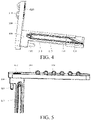
FIG. 4, FIG. 5 , andFIG. 6 are respectively partial schematic structural diagrams of an electronic device disclosed in an embodiment of the present invention from different perspectives; -
FIG. 7 is a partial schematic structural diagram of an electronic device disclosed in another embodiment of the present invention; -
FIG. 8 and FIG. 9 are respectively schematic structural diagrams of a functional module disclosed in an embodiment of the present invention from different perspectives; and -
FIG. 10 is a schematic structural diagram of another guide rail disclosed in an embodiment of the present invention. -
- 100-device body, 110-first accommodating space, 111-fourth electrical interface, 120-second accommodating space, 121-first guide post, 130-first opening, 140-first shell, 141-elastic arm, 150-second shell, 151-separator;
- 200-functional module, 210-first electrical interface, 220-second magnetic part, 230-sling hole;
- 300-connecting rod;
- 400-slider, 410-guide rail, 411-first limiting section, 412-extending section, 413-second limiting section, 414-retracting section, 415-first annular protrusion, 416-second annular protrusion, 420-second guide post;
- 500-driving part;
- 600-connecting base, 610-second electrical interface, 620-third electrical interface, 630-first magnetic part.
- To make the objectives, technical solutions, and advantages of the present invention clearer, the technical solutions of the present invention are described clearly and thoroughly below with reference to specific embodiments of the present invention and corresponding accompanying drawings. Apparently, the described embodiments are merely some embodiments rather than all of the embodiments of the present invention. All other embodiments derived by a person of ordinary skill in the art based on the embodiments of the present invention without creative efforts shall fall within the protection scope of the present invention.
- The technical solutions disclosed in the embodiments of the present invention are described below in detail with reference to the accompanying drawings.
- As shown in
FIG. 1 to FIG. 10 , an electronic device is disclosed in this embodiment of the present invention. The disclosed electronic device includes adevice body 100, afunctional module 200, and an ejection mechanism. - The
device body 100 is provided with a firstaccommodating space 110, a secondaccommodating space 120, and afirst opening 130 in communication with the firstaccommodating space 110. The secondaccommodating space 120 is in communication with the firstaccommodating space 110. Specifically, the secondaccommodating space 120 has a second opening. The firstaccommodating space 110 is in communication with the secondaccommodating space 120 through the second opening. The firstaccommodating space 110 can provide a mounting position for thefunctional module 200. Thefunctional module 200 can retract into the firstaccommodating space 110 through thefirst opening 130. Alternatively, at least a part of thefunctional module 200 can extend out of the firstaccommodating space 110 through thefirst opening 130. The secondaccommodating space 120 can provide a mounting position for the ejection mechanism. Thefirst opening 130 may be provided on asecond shell 150 of thedevice body 100. Optionally, thefirst opening 130 may be provided on a middle frame of thesecond shell 150. Thefirst opening 130 may also be provided at another position of thesecond shell 150. A specific position of thefirst opening 130 is not limited in the embodiments of the present invention. - The
functional module 200 may include at least one of a camera, a light filling module, a fingerprint identification module, a microphone, an electrical connection port, a data card, and a phone receiver. Certainly, thefunctional module 200 may also be another type of functional device. A specific type of thefunctional module 200 is not limited in the embodiments of the present invention. - The ejection mechanism includes a connecting
rod 300, aslider 400, and adriving part 500. Thefunctional module 200 is detachably connected to theslider 400. Aguide rail 410 is disposed on theslider 400. Theguide rail 410 includes a firstlimiting section 411, an extendingsection 412, a secondlimiting section 413, and aretracting section 414 connected in sequence. Both the extendingsection 412 and theretracting section 414 implement the function of connecting the first limitingsection 411 and the secondlimiting section 413. Specifically, one end of the first limitingsection 411 is connected to an opposite end of the second limitingsection 413 by the extendingsection 412, and an other end of the first limitingsection 411 is connected to an opposite end of the second limitingsection 413 by theretracting section 414. - In a specific installation process, at least a part of the driving
part 500 is disposed inside the secondaccommodating space 120, and the drivingpart 500 can drive theslider 400 to move along a direction perpendicular to thefirst opening 130. In a case that thefunctional module 200 is connected to theslider 400, the drivingpart 500 can drive theslider 400 to move and make at least a part of theslider 400 extend out of the secondaccommodating space 120 through the second opening, so as to push thefunctional module 200 to move and make at least a part of thefunctional module 200 extend out of the firstaccommodating space 110 through thefirst opening 130. The drivingpart 500 may be a spiral telescopic spring or an elastic rubber element. A specific type of the drivingpart 500 is not limited in the embodiments of the present invention. - A first end of the connecting
rod 300 is hinged to an inner wall of the secondaccommodating space 120, and a second end of the connectingrod 300 is slidably matched with theguide rail 410, so that the second end of the connectingrod 300 slides to respective parts of theguide rail 410 during the movement of theslider 400. Specifically, the first end of the connectingrod 300 is rotated, to enable the second end of the connectingrod 300 to adaptively is slidably matched with the first limitingsection 411, the extendingsection 412, the second limitingsection 413, and theretracting section 414. Both the matching between the second end of the connectingrod 300 and the first limitingsection 411, and the matching between the second end of the connectingrod 300 and the second limitingsection 413 can maintain theslider 400 at a specified position. In this case, in a case that theslider 400 is connected to thefunctional module 200, thefunctional module 200 can be maintained by theslider 400 at an extending position and a retracting position that are described above. - Optionally, the first limiting
section 411 may include a first sub-limiting section and a second sub-limiting section. The first sub-limiting section and the second sub-limiting section are disposed spaced apart. The second limitingsection 413 may be a broken-line limiting section. One end of the first sub-limiting section is connected to a first end of the broken-line limiting section by the extendingsection 412, and one end of the second sub-limiting section is connected to a second end of the broken-line limiting section by the retractingsection 414. Further, in an optional implementation, the extendingsection 412 and theretracting section 414 may be disposed opposite to each other and inclinedly. A distance between one end of the extendingsection 412 close to the first sub-limiting section and one end of theretracting section 414 close to the second sub-limiting section is a first distance, and a distance between one end of the extendingsection 412 close to the broken-line limiting section and one end of theretracting section 414 close to the broken-line limiting section is a second distance, where the first distance is smaller than the second distance, so that a part of theguide rail 410 may be in an "M"-shaped structure. In this embodiment of the present invention, the extendingsection 412 and theretracting section 414 are disposed inclinedly, to guide the second end of the connectingrod 300 better, so that the second end of the connectingrod 300 has smaller resistance when moving between the first limitingsection 411 and the second limitingsection 413, and slides more steadily, thereby preventing the second end of the connectingrod 300 from being suck during movement. - Optionally, as shown in
FIG. 4 , theguide rail 410 may be an annual rail. Specifically, a first end of the first limitingsection 411 is connected to the extendingsection 412, and a second end of the first limitingsection 411 is connected to theretracting section 414. A first end of the second limitingsection 413 is connected to the extendingsection 412, and a second end of the second limitingsection 413 is connected to theretracting section 414. In this case, when theslider 400 is connected to thefunctional module 200, in a case that thefunctional module 200 is continuously pressed by a user, the second end of the connectingrod 300 can slide relative to theguide rail 410. Referring toFIG. 4 again (the arrow in the figure refers to a movement direction of the second end of the connecting rod 300), the second end of the connectingrod 300 can enter theretracting section 414 from the first limitingsection 411, enter the second limitingsection 413 from the retractingsection 414, enter the extendingsection 412 from the second limitingsection 413, and enter the first limitingsection 411 from the extendingsection 412, and repeat the process in sequence as being pressed. The extendingsection 412 and theretracting section 414 implement a guiding function, to cause the second end of the connectingrod 300 to switch between matching the first limitingsection 411 and matching the second limitingsection 413, so that the movement of the second end of the connectingrod 300 is smoother. - In this embodiment of the present invention, the
functional module 200 has a first state and a second state. In a case that thefunctional module 200 is in the first state, thefunctional module 200 is separated from theslider 400. In this case, thefunctional module 200 may be separated from thedevice body 100, so that thefunctional module 200 can work away from thedevice body 100. - In a case that the
functional module 200 is in the second state, thefunctional module 200 is connected to theslider 400, and theslider 400 is movable between a first position and a second position. - Specifically, when the
slider 400 is at the first position, theslider 400 is located inside the secondaccommodating space 120, and the second end of the connectingrod 300 is matched with the second limitingsection 412 to restrict theslider 400 from moving toward thefirst opening 130. The matching between the second end of the connectingrod 300 and the second limitingsection 412 can maintain theslider 400 at the first position. When theslider 400 is at the second position, at least a part of theslider 400 is located outside the secondaccommodating space 120, and the second end of the connectingrod 300 is matched with the first limitingsection 411 to restrict theslider 400 from moving toward thefirst opening 130. The matching between the second end of the connectingrod 300 and the first limitingsection 411 can maintain theslider 400 at the second position. An acting force generated by the second end of the connectingrod 300 on theslider 400 is opposite to an acting force generated by the drivingpart 500 on theslider 400, so that theslider 400 can be maintained at a corresponding position. - Based on this, since the
functional module 200 is connected to theslider 400, in a case that theslider 400 is at the second position, at least a part of thefunctional module 200 is located outside the firstaccommodating space 110. In a case that theslider 400 is at the first position, thefunctional module 200 is located inside the firstaccommodating space 110. Therefore, thefunctional module 200 can be maintained at a corresponding position by maintaining theslider 400 at a corresponding position. - In use, after the
functional module 200 finishes working, the user may manually press thefunctional module 200. Further, thefunctional module 200 enables theslider 400 to overcome the acting force of the drivingpart 500. The second end of the connectingrod 300 can slide from the first limitingsection 411 through theretracting section 414 to a position at which the second end of the connectingrod 300 is matched with the second limitingsection 413. Theslider 400 is located at the first position to make thefunctional module 200 be located inside the firstaccommodating space 110. Under the action of the acting force of the drivingpart 500 and the matching of the second limitingsection 413, thefunctional module 200 can be maintained at the position inside the firstaccommodating space 110. When needing thefunctional module 200 to work, the user may press thefunctional module 200 again, to enable theslider 400 to overcome the acting force of the drivingpart 500. The second end of the connectingrod 300 may slide from the second limitingsection 413 through the extendingsection 412 to a position at which the second end of the connectingrod 300 is matched with the first limitingsection 411. At the same time, theslider 400 drives thefunctional module 200 to make at least a part of thefunctional module 200 extend out of the firstaccommodating space 110 through thefirst opening 130. Under the action of the acting force of the drivingpart 500 and the matching of the second limitingsection 413, theslider 400 can be maintained at the first position. In this case, at least a part of thefunctional module 200 may be maintained at a position inside the firstaccommodating space 110, and thefunctional module 200 may also be separated from theslider 400, so that thefunctional module 200 can work away from thedevice body 100. - It can be seen from the above working process that in the electronic device disclosed in the embodiments of the present invention, the
functional module 200 is detachably connected to theslider 400. Thefunctional module 200 can extend out of the firstaccommodating space 110 or retract into the firstaccommodating space 110 through theslider 400. Compared with that thefunctional module 200 of the existing electronic device needs to be connected to components, such as a driving motor and a speed reducer, to move, in the disclosed embodiments of the present invention, thefunctional module 200 and theslider 400 can be in a separated state, so that thefunctional module 200 not only can work outside the firstaccommodating space 110, but also can work separately from thedevice body 100. In addition, the user only needs to press thefunctional module 200 to implement installation and removal of thefunctional module 200, thereby facilitating driving of thefunctional module 200 and further improving the flexibility of thefunctional module 200. - Correspondingly, the above ejection mechanism is a manual driving mechanism, which enables the
functional module 200 to enter and exit the firstaccommodating space 110 without power consumption, so that the power consumption of the entire electronic device can be reduced. In addition, both thefunctional module 200 and the ejection mechanism have an independent installation space, so that the ejection mechanism drives thefunctional module 200 relatively steadily. - Further, to enable the ejection mechanism to drive the
functional module 200 more steady, in an optional solution, the ejection mechanism may further include a connectingbase 600. The connectingbase 600 may be connected to theslider 400, and theslider 400 is detachably connected to thefunctional module 200 by the connectingbase 600. In this case, theslider 400 may drive, through the connectingbase 600, thefunctional module 200 to move. It should be noted that in a telescopic direction of thefunctional module 200, the projection area of the connectingbase 600 is larger than the projection area of theslider 400. In this case, compared with a contact area between theslider 400 and thefunctional module 200, the contact area between the connectingbase 600 and thefunctional module 200 is larger, so that the driving forces of the connectingbase 600 on positions of thefunctional module 200 are evener, thereby enabling theslider 400 to drive thefunctional module 200 more steadily. - Optionally, in a case that the
functional module 200 is in the first state, the connectingbase 600 may be hermetically connected to thefirst opening 130. In this case, the connectingbase 600 may block thefirst opening 130, so that the firstaccommodating space 110 and the secondaccommodating space 120 form a sealed space, thereby implementing a water-proof and dust-proof function. Optionally, a seal ring may be disposed between the connectingbase 600 and thefirst opening 130, the connectingbase 600 may be hermetically connected to thefirst opening 130 by the seal ring. Certainly, the connectingbase 600 may also be hermetically connected to thefirst opening 130 in various manners. A specific manner in which the connectingbase 600 is hermetically connected to thefirst opening 130 is not limited in the embodiments of the present invention. - Further, in a case that the
functional module 200 is in the first state, an outer surface of the connectingbase 600 is flush with an outer surface on which thefirst opening 130 is located. In this case, when thefunctional module 200 is separated from thedevice body 100, the connectingbase 600 blocks thefirst opening 130, and an outer surface of the connectingbase 600 is flush with the outer surface on which thefirst opening 130 is located, which not only implements the water-proof and dust-proof function, but also makes the appearance of the electronic device better. - Correspondingly, in a case that the ejection mechanism includes the connecting
base 600, a firstelectrical interface 210 may be disposed on thefunctional module 200, a secondelectrical interface 610 may be disposed on one side of the connectingbase 600 facing away from theslider 400, and a thirdelectrical interface 620 may be disposed on one side of the connectingbase 600 facing theslider 400. The secondelectrical interface 610 is electrically connected to the thirdelectrical interface 620. A fourthelectrical interface 111 may be disposed in the firstaccommodating space 110. In a case that thefunctional module 200 is located inside the firstaccommodating space 110, the firstelectrical interface 210 may be electrically connected to the secondelectrical interface 610, and the thirdelectrical interface 620 may be electrically connected to the fourthelectrical interface 111. In conclusion, in this way, thefunctional module 200 may be electrically connected to thedevice body 100, so that thefunctional module 200 can implement functions such as data transmission and charging. - In the embodiments of the present invention, the
functional module 200 may be detachably connected to the connectingbase 600 in various manners. For example, thefunctional module 200 may be connected to the connectingbase 600 in a manner such as engagement, a threaded connection, or magnetic attraction. Optionally, a firstmagnetic part 630 may be disposed on one of thefunctional module 200 or one side of the connectingbase 600 facing away from theslider 400, and a secondmagnetic part 220 may be disposed on the other thereof. In a case that thefunctional module 200 is in the second state, the firstmagnetic part 630 is magnetically connected to the secondmagnetic part 220. Compared with other manners, such a manner not only facilitates the connection between thefunctional module 200 and the connectingbase 600, but also helps the user to relatively easily take out thefunctional module 200 from the firstaccommodating space 110. - Further, the first
magnetic part 630 may be disposed on thefunctional module 200, and the secondmagnetic part 220 may be disposed on the one side of the connectingbase 600 facing away from theslider 400. In addition, the secondmagnetic part 220 may be an electromagnet. In a case that thefunctional module 200 is located inside the firstaccommodating space 110, in view of the above, the connectingbase 600 may be electrically connected to the fourthelectrical interface 111 through the thirdelectrical interface 620. Therefore, the secondmagnetic part 220 on the connectingbase 600 is energized to generate magnetic attraction, so that the firstmagnetic part 630 is magnetically connected to the secondmagnetic part 220, so that thefunctional module 200 can be maintained in the firstaccommodating space 110. In addition, in a case that at least a part of theslider 400 is located outside the secondaccommodating space 120, the secondmagnetic part 220 on the connectingbase 600 is not energized, so that there is no magnetic attraction between the firstmagnetic part 630 and the secondmagnetic part 220, thereby enabling the user to relatively easily take out thefunctional module 200 from the firstaccommodating space 110. - In the embodiments of the present invention, in an optional solution, the driving
part 500 may be an elastic member. One end of the elastic member may be connected to the inner wall of the secondaccommodating space 120, and an other end of the elastic member may be connected to theslider 400. Compared with the drivingpart 500 with another structure, the elastic member has a larger elastic deformation capability, which makes it easier to drive theslider 400. In addition, in a case that the drivingpart 500 is an elastic member, the service life of the drivingpart 500 can further be prolonged. The elastic member may be a telescopic spring. Certainly, the elastic member may also be another elastic component. A specific structure of the elastic member is not limited in the present invention. - In an actual assembly process, to improve the assembly performance, in an optional solution, a
first guide post 121 may be disposed on the inner wall of the secondaccommodating space 120, and asecond guide post 420 may be disposed on theslider 400. One end of the elastic member overlaps with thefirst guide post 121, and an other end of the elastic member overlaps with thesecond guide post 420, so as to facilitate the installation and removal of the elastic member. - In this embodiment of the present invention, in another optional solution, the driving
part 500 may include a third magnetic part and a fourth magnetic part. The third magnetic part may be disposed inside the secondaccommodating space 120, and the fourth magnetic part may be connected to theslider 400. The third magnetic part and the fourth magnetic part are disposed opposite to each other, and the third magnetic part has the same magnetic property as the fourth magnetic part. In this case, an acting force toward thefirst opening 130 is generated due to the repulsion between the third magnetic part and the fourth magnetic part that have the same magnetic property, thereby indirectly causing theslider 400 to have an acting force toward thefirst opening 130, and eventually, drive theslider 400. In this way, the driving forces received by theslider 400 are evener, so that the movement of theslider 400 is more steady. - In the embodiments disclosed in the present invention, the second end of the connecting
rod 300 maintains the position of theslider 400, and there may be various specific structures of the second end of the connectingrod 300. In an optional solution, the second end of the connectingrod 300 may be a retractor. The retractor is hung on theguide rail 410. The retractor is hung on the first limitingsection 411 and the second limitingsection 413 respectively to be matched with the first limitingsection 411 and the second limitingsection 413 respectively in a limiting manner. Specifically, in a case that at least a part of thefunctional module 200 is located outside the firstaccommodating space 110, the retractor is hung on and is matched with the first limitingsection 411, and in this case, at least part of theslider 400 is located outside the secondaccommodating space 120. In a case that thefunctional module 200 is located inside the firstaccommodating space 110, the retractor is hung on and is matched with the second limitingsection 413, and in this case theslider 400 is located inside the secondaccommodating space 120. In this case, the second end of the connectingrod 300 is disposed between thefirst opening 130 and the first end of the connectingrod 300. The connectingrod 300 exerts a pulling force on theslider 400, so as to restrict theslider 400 from moving toward the extending direction of thefunctional module 200, so that theslider 400 can be maintained at the first position or the second position. Both the first limitingsection 411 and the second limitingsection 413 may be concave, to be conveniently hung on by the retractor in a limiting manner. - Certainly, in the above embodiments, the first end of the connecting
rod 300 is located on one side of theslider 400 facing away from thefirst opening 130, so that the entire connectingrod 300 is closer to a central region of thedevice body 100. Since a circuit board and many electronic components disposed in the central region of thedevice body 100, the connectingrod 300 is likely to interfere with the circuit board or the electronic components. Therefore, in another optional solution, the second end of the connectingrod 300 may be an abutting part, and the abutting part abuts against theguide rail 410. Specifically, in a case that at least a part of thefunctional module 200 is located outside the firstaccommodating space 110, the abutting part abuts against the second limitingsection 413, and in this case, theslider 400 is located outside the secondaccommodating space 120. In a case that thefunctional module 200 is located inside the firstaccommodating space 110, the abutting part abuts against the first limitingsection 411, and in this case, theslider 400 is located inside the secondaccommodating space 120. In this case, the first end of the connectingrod 300 is located between thefirst opening 130 and the second end of the connectingrod 300. The acting force exerted by the abutting part on theslider 400 may be a thrust force. Similarly, both the first limitingsection 411 and the second limitingsection 413 may be concave, to be conveniently abutted against by the abutting part in a limiting manner. The first limitingsection 411 and the second limitingsection 413 may also be of other structures provided that the abutting part can be matched with the first limitingsection 411 and the second limitingsection 413 in a limiting manner, so that theslider 400 can be maintained at the first position or the second position under the limitation of the abutting part. - As can be learned from the above, in this manner, the first end of the connecting
rod 300 is located on one side of theslider 400 facing thefirst opening 130, so that the connectingrod 300 is closer to an edge of thedevice body 100. Since there are fewer electronic components distributed on the edge of thedevice body 100, the connectingrod 300 can be prevented from interfering with the electronic components in thedevice body 100. - In the embodiments of the present invention, the first limiting
section 411, the extendingsection 412, the second limitingsection 413, and theretracting section 414 may be a groove section with various structures. Referring toFIG. 4 , the extendingsection 412 may be a straight groove section, so that thefunctional module 200 can extend more quickly. Optionally, the retractingsection 414 may include an arc-shaped groove section. Since thefunctional module 200 needs to be pressed by the user for a longer time during retraction, an arc-shaped groove section has a certain curvature to better guide the second end of the connectingrod 300 to a position at which the second end of the connectingrod 300 is matched with the first limitingsection 411. - The
guide rail 410 may also be another structure and not limited to a groove-shaped structure. In one specific embodiment, theguide rail 410 may be a convex guide part. Specifically, referring toFIG. 10 , the convex guide part may include a firstannular protrusion 415 and a secondannular protrusion 416, and a region between the firstannular protrusion 415 and the secondannular protrusion 416 is theguide rail 410. In this case, the first limitingsection 411, the extendingsection 412, the second limitingsection 413, and theretracting section 414 all may be at least a part of the region between the firstannular protrusion 415 and the secondannular protrusion 416. During working, a sliding stroke of the second end of the connectingrod 300 may be as shown inFIG. 10 , and a direction in which the second end of the connectingrod 300 slides relative to theguide rail 410 is schematically shown by a dashed arrow inFIG. 10 . In this way, the sliding of the second end of the connectingrod 300 is smoother, thereby preventing the second end of the connectingrod 300 from being stuck during movement. Certainly, the firstannular protrusion 415 and the secondannular protrusion 416 may be formed by injection molding or in another manner. A specific forming manner of the firstannular protrusion 415 and the secondannular protrusion 416 is not limited in the present invention. - In the embodiments of the present invention, during the movement of the
slider 400, the second end of the connectingrod 300 may be disengaged from theguide rail 410. Therefore, to achieve more steady sliding and matching, thedevice body 100 may further include afirst shell 140. Thefirst shell 140 may be provided with a sliding cavity. At least a part of theslider 400 may be located in the sliding cavity and at least a part of the connectingrod 300 may be located in the sliding cavity. In this case, the second end of the connectingrod 300 may slide inside the sliding cavity, so that the second end of the connectingrod 300 is prevented from being disengaged from theguide rail 410, thereby improving the sliding stability of the second end of the connectingrod 300. - Further, to enable the second end of the connecting
rod 300 to better slide in theguide rail 410, thefirst shell 140 may include anelastic arm 141. At least a part of the connectingrod 300 may be located between theelastic arm 141 and theguide rail 410. In this case, due to the elastic effect of theelastic arm 141, the second end of the connectingrod 300 can better slide in theguide rail 410, thereby preventing the second end of the connectingrod 300 from being disengaged from theguide rail 410. - After the above structure is adopted, at least a part of the connecting
rod 300 may slide between theelastic arm 141 and theguide rail 410. Based on this, optionally, the elasticity of theelastic arm 141 enables the second end of the connectingrod 300 to snugly fit theguide rail 410, so that the second end of the connectingrod 300 can be prevented from swinging between theelastic arm 141 and theguide rail 410, thereby better preventing the second end of the connectingrod 300 from being disengaged from the sliding of theguide rail 410. - In the electronic device disclosed in the embodiments of the present invention, the
functional module 200 can be separated from thedevice body 100, and thedevice body 100 can remotely control thefunctional module 200 to work. In a case that thefunctional module 200 is separated from thedevice body 100, the firstaccommodating space 110 and the secondaccommodating space 120 may come into contact with an external environment, which is not conducive to the water-proof and dust-proof performance of the electronic device. Therefore, in one optional solution, thedevice body 100 may include asecond shell 150. Thesecond shell 150 has an inner cavity. Thesecond shell 150 may include aseparator 151. Theseparator 151 may be disposed inside the inner cavity. Theseparator 151 separates the inner cavity into a first sub-cavity, a second sub-cavity, and a third sub-cavity. The first sub-cavity and the second sub-cavity is hermetically separated from the third sub-cavity. The first sub-cavity is in communication with the second sub-cavity. The first sub-cavity is the firstaccommodating space 110, and the second sub-cavity is the secondaccommodating space 120. In this way, impurities can be prevented from entering into the inner space of thedevice body 100 through the firstaccommodating space 110 or the secondaccommodating space 120, thereby producing better water-proof and dust-proof effects. - The volume of the
functional module 200 is generally small. When thefunctional module 200 is separated from thedevice body 100, thefunctional module 200 is easily lost. Therefore, thefunctional module 200 may include a functional module body and a sling, and the functional module body may be provided with asling hole 230. The sling may be detachably connected to the functional module body by thesling hole 230. In this case, when the functional module body is separated from thedevice body 100, the user can carry the functional module body through the sling, thereby preventing the functional module body from being lost. - The electronic device disclosed in the embodiments of the present invention may be a device such as a smartphone, a tablet computer, an e-book reader, a wearable device, or an electronic game console. A specific type of the electronic device is not limited in the embodiments of the present invention.
- In the foregoing embodiments of the present invention, the differences between various embodiments are mainly described. The embodiments may all be combined to form better embodiments provided that the different optimization features of the various embodiments are not contradictory. In consideration of the brevity of the text, details are not described herein again.
- The above descriptions are merely embodiments of the present invention, and are not intended to limit the present invention. A person skilled in the art may make various alterations and variations to the present invention. Any modification, equivalent replacement, or improvement made within the spirit and principle of the present invention shall fall within the protection scope of the present invention.
Claims (14)
- An electronic device, comprising:a device body (100), wherein the device body (100) is provided with a first accommodating space (110), a second accommodating space (120), and a first opening (130) in communication with the first accommodating space (110), wherein the second accommodating space (120) is in communication with the first accommodating space (110);a functional module (200), wherein the functional module (200) has a first state and a second state;an ejection mechanism, wherein the ejection mechanism comprises a connecting rod (300), a slider (400), and a driving part (500), wherein the functional module (200) is detachably connected to the slider (400), and a guide rail (410) is disposed on the slider (400), wherein the guide rail (410) comprises a first limiting section (411), an extending section (412), a second limiting section (413) and a retracting section (414) connected in sequence;at least a part of the driving parts (500) is disposed inside the second accommodating space (120), the driving parts (500) drives the slider (400) to move along a direction perpendicular to the first opening (130), a first end of the connecting rod (300) is hinged to an inner wall of the second accommodating space (120), and a second end of the connecting rod (300) is slidably matched with the guide rail (410);in a case that the functional module (200) is in the first state, the functional module (200) is separated from the slider (400);in a case that the functional module (200) is in the second state, the functional module (200) is connected to the slider (400), and the slider (400) is movable between a first position and a second position, when the slider (400) is located at the first position, the slider (400) is located inside the second accommodating space (120), and when the slider (400) is located at the second position, at least a part of the slider (400) is located outside the second accommodating space (120);in a case that the slider (400) is located at the second position, at least a part of the functional module (200) is located outside the first accommodating space (110), and the second end of the connecting rod (300) is matched with the first limiting section (411); andin a case that the slider (400) is located at the first position, the functional module (200) is located inside the first accommodating space (110), and the second end of the connecting rod (300) is matched with the second limiting section (413).
- The electronic device according to claim 1, wherein the ejection mechanism further comprises a connecting base (600), the connecting base (600) is connected to the slider (400), the slider (400) is detachably connected to the functional module (200) by the connecting base (600), and in a telescopic direction of the function module (200), the projection area of the connecting base (600) is larger than the projection area of the slider (400).
- The electronic device according to claim 2, wherein in a case that the functional module (200) is in the first state, the connecting base (600) is hermetically connected to the first opening (130).
- The electronic device according to claim 3, wherein in a case that the functional module (200) is in the first state, an outer surface of the connecting base (600) is flush with an outer surface on which the first opening (130) is located.
- The electronic device according to claim 2, wherein a first electrical interface (210) is disposed on the functional module (200), a second electrical interface (610) is disposed on one side of the connecting base (600) facing away from the slider (400), a third electrical interface (620) is disposed on one side of the connecting base (600) facing the slider (400), the second electrical interface (610) is electrically connected to the third electrical interface (620), a fourth electrical interface (111) is disposed on the first accommodating space (110), in a case that the functional module (200) is located inside the first accommodating space (110), the first electrical interface (210) is electrically connected to the second electrical interface (610), and the third electrical interface (620) is electrically connected to the fourth electrical interface (111).
- The electronic device according to claim 2, wherein a first magnetic part (630) is disposed on one of the functional module (200) or one side of the connecting base (600) facing away from the slider (400), a second magnetic part (220) is disposed on the other thereof, and in a case that the functional module (200) is in the second state, the first magnetic part (630) is magnetically connected to the second magnetic part (220).
- The electronic device according to claim 1, wherein the driving part (500) is an elastic member, one end of the elastic member is connected to the inner wall of the second accommodating space (120), and an other end of the elastic member is connected to the slider (400).
- The electronic device according to claim 7, wherein a first guide post (121) is disposed on the inner wall of the second accommodating space (120), a second guide post (420) is disposed on the slider (400), one end of the elastic member overlaps with the first guide post (121), and an other end of the elastic member overlaps with the second guide post (420).
- The electronic device according to claim 1, wherein the driving part (500) comprises a third magnetic part and a fourth magnetic part, wherein the third magnetic part is disposed inside the second accommodating space (120), the fourth magnetic part is connected to the slider (400), the third magnetic part and the fourth magnetic part are disposed opposite to each other, and the third magnetic part has the same magnetic property as the fourth magnetic part.
- The electronic device according to claim 1, wherein the second end of the connecting rod (300) is a retractor, and the retractor is hung on the guide rail (410), or the second end of the connecting rod (300) is an abutting part, and the abutting part abuts against the guide rail (410).
- The electronic device according to claim 1, wherein the device body (100) further comprises a first shell (140), the first shell (140) is provided with a sliding cavity, at least a part of the slider (400) is located in the sliding cavity, and at least a part of the connecting rod (300) is located in the sliding cavity.
- The electronic device according to claim 11, wherein the first shell (140) comprises an elastic arm (141), and at least a part of the connecting rod (300) is located between the elastic arm (141) and the guide rail (410).
- The electronic device according to claim 1, wherein the device body (100) comprises a second shell (150), the second shell (150) has an inner cavity, the second shell (150) comprises a separator (151), the separator (151) is disposed inside the inner cavity, the separator (151) separates the inner cavity into a first sub-cavity, a second sub-cavity, and a third sub-cavity, the first sub-cavity and the second sub-cavity are hermetically separated from the third sub-cavity, the first sub-cavity is in communication with the second sub-cavity, the first sub-cavity is the first accommodating space (110), and the second sub-cavity is the second accommodating space (120).
- The electronic device according to claim 1, wherein the guide rail (410) is an annular rail, a first end of the first limiting section (411) is connected to the extending section (412), a second end of the first limiting section (411) is connected to the retracting section (414), a first end of the second limiting section (413) is connected to the extending section (412), and a second end of the second limiting section (413) is connected to the retracting section (414).
Applications Claiming Priority (2)
| Application Number | Priority Date | Filing Date | Title |
|---|---|---|---|
| CN202010136441.XA CN111432593B (en) | 2020-03-02 | 2020-03-02 | Electronic device |
| PCT/CN2021/074668 WO2021175060A1 (en) | 2020-03-02 | 2021-02-01 | Electronic device |
Publications (3)
| Publication Number | Publication Date |
|---|---|
| EP4117255A1 true EP4117255A1 (en) | 2023-01-11 |
| EP4117255A4 EP4117255A4 (en) | 2023-08-09 |
| EP4117255B1 EP4117255B1 (en) | 2025-05-28 |
Family
ID=71547418
Family Applications (1)
| Application Number | Title | Priority Date | Filing Date |
|---|---|---|---|
| EP21763970.7A Active EP4117255B1 (en) | 2020-03-02 | 2021-02-01 | Electronic device |
Country Status (7)
| Country | Link |
|---|---|
| US (1) | US12029002B2 (en) |
| EP (1) | EP4117255B1 (en) |
| JP (1) | JP7554277B2 (en) |
| KR (1) | KR102697328B1 (en) |
| CN (1) | CN111432593B (en) |
| ES (1) | ES3034148T3 (en) |
| WO (1) | WO2021175060A1 (en) |
Families Citing this family (8)
| Publication number | Priority date | Publication date | Assignee | Title |
|---|---|---|---|---|
| CN111432593B (en) | 2020-03-02 | 2021-07-13 | 维沃移动通信有限公司 | Electronic device |
| CN114098998B (en) * | 2020-08-31 | 2023-08-01 | 疆域康健创新医疗科技成都有限公司 | Ejecting device |
| CN112186838B (en) * | 2020-09-18 | 2023-07-21 | 维沃移动通信有限公司 | Wearable device, control method and control device for wearable device |
| CN112467827B (en) * | 2020-11-10 | 2023-12-22 | 维沃移动通信有限公司 | Charging equipment |
| CN112540648B (en) * | 2020-12-07 | 2024-12-20 | 维沃移动通信有限公司 | Electronic devices |
| CN116940045A (en) * | 2022-03-30 | 2023-10-24 | 欧姆龙(上海)有限公司 | Mounting assembly for guide rail and electric product |
| CN115949656A (en) * | 2022-12-30 | 2023-04-11 | 广东安达智能装备股份有限公司 | A functional module connection structure and an intelligent platform system |
| CN118795983B (en) * | 2024-05-29 | 2025-11-28 | 荣耀终端股份有限公司 | Storage mechanism and electronic equipment |
Family Cites Families (24)
| Publication number | Priority date | Publication date | Assignee | Title |
|---|---|---|---|---|
| US5825616A (en) * | 1997-01-21 | 1998-10-20 | Dell Usa, L.P. | Media module locking and ejecting mechanism |
| KR100428794B1 (en) * | 2000-09-14 | 2004-04-28 | 삼성전자주식회사 | Docking mechanism used for assembling/disassembling peripheral device of computer |
| JP2003196646A (en) | 2001-12-21 | 2003-07-11 | Yasuko Nagamine | Fingerprint certification unit and electronic equipment |
| CN206004717U (en) * | 2016-07-21 | 2017-03-08 | 河南首弘电子科技有限公司 | A kind of 4G projection mobile phone automatically turns on projection arrangement |
| WO2018022096A1 (en) * | 2016-07-29 | 2018-02-01 | Hewlett-Packard Development Company, L.P. | Electronic card holders |
| CN107911579A (en) | 2017-11-07 | 2018-04-13 | 广东欧珀移动通信有限公司 | mobile terminal |
| CN109933141B (en) * | 2017-12-15 | 2021-03-09 | Oppo广东移动通信有限公司 | Functional assembly, electronic device and control method thereof |
| CN109995904B (en) | 2017-12-29 | 2021-03-02 | Oppo广东移动通信有限公司 | Functional module, electronic device and control method of electronic device |
| CN207968575U (en) * | 2018-02-09 | 2018-10-12 | 广东欧珀移动通信有限公司 | Mobile terminal |
| CN207869232U (en) * | 2018-03-10 | 2018-09-14 | 深圳市安嘉科技有限公司 | A kind of easy-to-dismount video camera module |
| CN207926736U (en) * | 2018-03-14 | 2018-09-28 | 珠海格力电器股份有限公司 | Mobile terminal |
| US20190301689A1 (en) * | 2018-04-03 | 2019-10-03 | Eaton Intelligent Power Limited | Configurable And Modular Light Fixtures |
| CN110519418A (en) * | 2018-05-22 | 2019-11-29 | Oppo广东移动通信有限公司 | Functional unit and electronic equipment |
| WO2019228324A1 (en) * | 2018-05-31 | 2019-12-05 | Oppo广东移动通信有限公司 | Mobile terminal |
| CN110557470B (en) * | 2018-05-31 | 2024-07-26 | Oppo广东移动通信有限公司 | Mobile Terminal |
| CN108495018B (en) * | 2018-06-08 | 2020-12-22 | Oppo广东移动通信有限公司 | Photographing device, photographing method and electronic equipment |
| CN109379517B (en) * | 2018-11-06 | 2021-03-12 | Oppo(重庆)智能科技有限公司 | Electronic device |
| CN109218480B (en) | 2018-11-06 | 2021-01-08 | 维沃移动通信(杭州)有限公司 | Terminal device |
| CN209330169U (en) * | 2018-11-30 | 2019-08-30 | Oppo广东移动通信有限公司 | mobile terminal |
| CN209748616U (en) * | 2019-06-12 | 2019-12-06 | 向凯凯 | Mobile phone separated rear camera |
| CN110581938B (en) * | 2019-08-06 | 2024-05-03 | 深圳传音控股股份有限公司 | Mobile terminal, mobile terminal control method, and computer storage medium |
| KR20220058813A (en) * | 2019-09-06 | 2022-05-10 | 삼성전자주식회사 | Electronics and Camera Movement Assemblies |
| CN111432593B (en) * | 2020-03-02 | 2021-07-13 | 维沃移动通信有限公司 | Electronic device |
| CN111405086B (en) * | 2020-03-02 | 2021-09-14 | 维沃移动通信有限公司 | Electronic device |
-
2020
- 2020-03-02 CN CN202010136441.XA patent/CN111432593B/en active Active
-
2021
- 2021-02-01 KR KR1020227033677A patent/KR102697328B1/en active Active
- 2021-02-01 EP EP21763970.7A patent/EP4117255B1/en active Active
- 2021-02-01 JP JP2022552202A patent/JP7554277B2/en active Active
- 2021-02-01 ES ES21763970T patent/ES3034148T3/en active Active
- 2021-02-01 WO PCT/CN2021/074668 patent/WO2021175060A1/en not_active Ceased
-
2022
- 2022-08-16 US US17/888,887 patent/US12029002B2/en active Active
Also Published As
| Publication number | Publication date |
|---|---|
| CN111432593B (en) | 2021-07-13 |
| JP2023516313A (en) | 2023-04-19 |
| ES3034148T3 (en) | 2025-08-13 |
| EP4117255B1 (en) | 2025-05-28 |
| JP7554277B2 (en) | 2024-09-19 |
| KR20220146607A (en) | 2022-11-01 |
| EP4117255A4 (en) | 2023-08-09 |
| US12029002B2 (en) | 2024-07-02 |
| CN111432593A (en) | 2020-07-17 |
| WO2021175060A1 (en) | 2021-09-10 |
| KR102697328B1 (en) | 2024-08-23 |
| US20220400570A1 (en) | 2022-12-15 |
Similar Documents
| Publication | Publication Date | Title |
|---|---|---|
| US12029002B2 (en) | Electronic device | |
| US12160962B2 (en) | Electronic device | |
| US11381725B2 (en) | Electronic devices and method for controlling camera module | |
| US10841475B2 (en) | Camera assembly and electronic device | |
| CN112306158B (en) | Foldable device and foldable electronic equipment | |
| CN109769054B (en) | Shell assembly and intelligent terminal with same | |
| EP4131897B1 (en) | Electronic device | |
| CN109992045B (en) | Functional component, electronic device and control method thereof | |
| WO2020199922A1 (en) | Terminal device | |
| CN111614813A (en) | Electronic equipment | |
| US12342063B2 (en) | Camera module and electronic device including a protection structural member, a gimbal camera and a support seat | |
| CN109995904A (en) | The control method of functional unit, electronic device and electronic device | |
| CN109922182B (en) | Terminal device | |
| CN110650223B (en) | Telescopic mechanism, camera device and terminal | |
| CN210297792U (en) | Electronic equipment | |
| WO2020207381A1 (en) | Terminal device | |
| CN110518741A (en) | Electronic equipment | |
| CN109962998B (en) | Functional component, electronic device and control method thereof | |
| CN109862238B (en) | Functional assembly, mobile terminal and control method of mobile terminal | |
| CN120529177A (en) | electronic devices |
Legal Events
| Date | Code | Title | Description |
|---|---|---|---|
| STAA | Information on the status of an ep patent application or granted ep patent |
Free format text: STATUS: THE INTERNATIONAL PUBLICATION HAS BEEN MADE |
|
| PUAI | Public reference made under article 153(3) epc to a published international application that has entered the european phase |
Free format text: ORIGINAL CODE: 0009012 |
|
| STAA | Information on the status of an ep patent application or granted ep patent |
Free format text: STATUS: REQUEST FOR EXAMINATION WAS MADE |
|
| 17P | Request for examination filed |
Effective date: 20220923 |
|
| AK | Designated contracting states |
Kind code of ref document: A1 Designated state(s): AL AT BE BG CH CY CZ DE DK EE ES FI FR GB GR HR HU IE IS IT LI LT LU LV MC MK MT NL NO PL PT RO RS SE SI SK SM TR |
|
| DAV | Request for validation of the european patent (deleted) | ||
| DAX | Request for extension of the european patent (deleted) | ||
| A4 | Supplementary search report drawn up and despatched |
Effective date: 20230710 |
|
| RIC1 | Information provided on ipc code assigned before grant |
Ipc: G06F 1/16 20060101ALI20230704BHEP Ipc: H04M 1/02 20060101AFI20230704BHEP |
|
| GRAP | Despatch of communication of intention to grant a patent |
Free format text: ORIGINAL CODE: EPIDOSNIGR1 |
|
| STAA | Information on the status of an ep patent application or granted ep patent |
Free format text: STATUS: GRANT OF PATENT IS INTENDED |
|
| INTG | Intention to grant announced |
Effective date: 20250220 |
|
| GRAS | Grant fee paid |
Free format text: ORIGINAL CODE: EPIDOSNIGR3 |
|
| GRAA | (expected) grant |
Free format text: ORIGINAL CODE: 0009210 |
|
| STAA | Information on the status of an ep patent application or granted ep patent |
Free format text: STATUS: THE PATENT HAS BEEN GRANTED |
|
| AK | Designated contracting states |
Kind code of ref document: B1 Designated state(s): AL AT BE BG CH CY CZ DE DK EE ES FI FR GB GR HR HU IE IS IT LI LT LU LV MC MK MT NL NO PL PT RO RS SE SI SK SM TR |
|
| REG | Reference to a national code |
Ref country code: GB Ref legal event code: FG4D |
|
| REG | Reference to a national code |
Ref country code: CH Ref legal event code: EP |
|
| REG | Reference to a national code |
Ref country code: IE Ref legal event code: FG4D Ref country code: DE Ref legal event code: R096 Ref document number: 602021031457 Country of ref document: DE |
|
| REG | Reference to a national code |
Ref country code: NL Ref legal event code: FP |
|
| REG | Reference to a national code |
Ref country code: ES Ref legal event code: FG2A Ref document number: 3034148 Country of ref document: ES Kind code of ref document: T3 Effective date: 20250813 |
|
| PG25 | Lapsed in a contracting state [announced via postgrant information from national office to epo] |
Ref country code: FI Free format text: LAPSE BECAUSE OF FAILURE TO SUBMIT A TRANSLATION OF THE DESCRIPTION OR TO PAY THE FEE WITHIN THE PRESCRIBED TIME-LIMIT Effective date: 20250528 |
|
| REG | Reference to a national code |
Ref country code: LT Ref legal event code: MG9D |
|
| PG25 | Lapsed in a contracting state [announced via postgrant information from national office to epo] |
Ref country code: GR Free format text: LAPSE BECAUSE OF FAILURE TO SUBMIT A TRANSLATION OF THE DESCRIPTION OR TO PAY THE FEE WITHIN THE PRESCRIBED TIME-LIMIT Effective date: 20250829 Ref country code: NO Free format text: LAPSE BECAUSE OF FAILURE TO SUBMIT A TRANSLATION OF THE DESCRIPTION OR TO PAY THE FEE WITHIN THE PRESCRIBED TIME-LIMIT Effective date: 20250828 |
|
| PG25 | Lapsed in a contracting state [announced via postgrant information from national office to epo] |
Ref country code: PL Free format text: LAPSE BECAUSE OF FAILURE TO SUBMIT A TRANSLATION OF THE DESCRIPTION OR TO PAY THE FEE WITHIN THE PRESCRIBED TIME-LIMIT Effective date: 20250528 |
|
| PG25 | Lapsed in a contracting state [announced via postgrant information from national office to epo] |
Ref country code: BG Free format text: LAPSE BECAUSE OF FAILURE TO SUBMIT A TRANSLATION OF THE DESCRIPTION OR TO PAY THE FEE WITHIN THE PRESCRIBED TIME-LIMIT Effective date: 20250528 |
|
| PG25 | Lapsed in a contracting state [announced via postgrant information from national office to epo] |
Ref country code: HR Free format text: LAPSE BECAUSE OF FAILURE TO SUBMIT A TRANSLATION OF THE DESCRIPTION OR TO PAY THE FEE WITHIN THE PRESCRIBED TIME-LIMIT Effective date: 20250528 |
|
| PG25 | Lapsed in a contracting state [announced via postgrant information from national office to epo] |
Ref country code: RS Free format text: LAPSE BECAUSE OF FAILURE TO SUBMIT A TRANSLATION OF THE DESCRIPTION OR TO PAY THE FEE WITHIN THE PRESCRIBED TIME-LIMIT Effective date: 20250828 |
|
| PG25 | Lapsed in a contracting state [announced via postgrant information from national office to epo] |
Ref country code: IS Free format text: LAPSE BECAUSE OF FAILURE TO SUBMIT A TRANSLATION OF THE DESCRIPTION OR TO PAY THE FEE WITHIN THE PRESCRIBED TIME-LIMIT Effective date: 20250928 |
|
| PG25 | Lapsed in a contracting state [announced via postgrant information from national office to epo] |
Ref country code: LV Free format text: LAPSE BECAUSE OF FAILURE TO SUBMIT A TRANSLATION OF THE DESCRIPTION OR TO PAY THE FEE WITHIN THE PRESCRIBED TIME-LIMIT Effective date: 20250528 |
|
| REG | Reference to a national code |
Ref country code: AT Ref legal event code: MK05 Ref document number: 1799316 Country of ref document: AT Kind code of ref document: T Effective date: 20250528 |
|
| PG25 | Lapsed in a contracting state [announced via postgrant information from national office to epo] |
Ref country code: AT Free format text: LAPSE BECAUSE OF FAILURE TO SUBMIT A TRANSLATION OF THE DESCRIPTION OR TO PAY THE FEE WITHIN THE PRESCRIBED TIME-LIMIT Effective date: 20250528 Ref country code: DK Free format text: LAPSE BECAUSE OF FAILURE TO SUBMIT A TRANSLATION OF THE DESCRIPTION OR TO PAY THE FEE WITHIN THE PRESCRIBED TIME-LIMIT Effective date: 20250528 Ref country code: SM Free format text: LAPSE BECAUSE OF FAILURE TO SUBMIT A TRANSLATION OF THE DESCRIPTION OR TO PAY THE FEE WITHIN THE PRESCRIBED TIME-LIMIT Effective date: 20250528 |
|
| PGFP | Annual fee paid to national office [announced via postgrant information from national office to epo] |
Ref country code: FR Payment date: 20251231 Year of fee payment: 6 |
|
| PG25 | Lapsed in a contracting state [announced via postgrant information from national office to epo] |
Ref country code: CZ Free format text: LAPSE BECAUSE OF FAILURE TO SUBMIT A TRANSLATION OF THE DESCRIPTION OR TO PAY THE FEE WITHIN THE PRESCRIBED TIME-LIMIT Effective date: 20250528 |
|
| PG25 | Lapsed in a contracting state [announced via postgrant information from national office to epo] |
Ref country code: EE Free format text: LAPSE BECAUSE OF FAILURE TO SUBMIT A TRANSLATION OF THE DESCRIPTION OR TO PAY THE FEE WITHIN THE PRESCRIBED TIME-LIMIT Effective date: 20250528 |
|
| PG25 | Lapsed in a contracting state [announced via postgrant information from national office to epo] |
Ref country code: SK Free format text: LAPSE BECAUSE OF FAILURE TO SUBMIT A TRANSLATION OF THE DESCRIPTION OR TO PAY THE FEE WITHIN THE PRESCRIBED TIME-LIMIT Effective date: 20250528 |
|
| PGFP | Annual fee paid to national office [announced via postgrant information from national office to epo] |
Ref country code: NL Payment date: 20260106 Year of fee payment: 6 |
|
| REG | Reference to a national code |
Ref country code: DE Ref legal event code: R097 Ref document number: 602021031457 Country of ref document: DE |
|
| PLBE | No opposition filed within time limit |
Free format text: ORIGINAL CODE: 0009261 |
|
| STAA | Information on the status of an ep patent application or granted ep patent |
Free format text: STATUS: NO OPPOSITION FILED WITHIN TIME LIMIT |
|
| PGFP | Annual fee paid to national office [announced via postgrant information from national office to epo] |
Ref country code: GB Payment date: 20260106 Year of fee payment: 6 |
|
| REG | Reference to a national code |
Ref country code: CH Ref legal event code: L10 Free format text: ST27 STATUS EVENT CODE: U-0-0-L10-L00 (AS PROVIDED BY THE NATIONAL OFFICE) Effective date: 20260409 |
|
| PGFP | Annual fee paid to national office [announced via postgrant information from national office to epo] |
Ref country code: ES Payment date: 20260311 Year of fee payment: 6 |
|
| PGFP | Annual fee paid to national office [announced via postgrant information from national office to epo] |
Ref country code: DE Payment date: 20251230 Year of fee payment: 6 |
|
| PGFP | Annual fee paid to national office [announced via postgrant information from national office to epo] |
Ref country code: IT Payment date: 20260122 Year of fee payment: 6 |
|
| 26N | No opposition filed |
Effective date: 20260303 |