EP4117230B1 - Authentifizierungsverfahren zwischen endgeräten, die eine nahkommunikationsfunktion aufweisen, und endgeräten, die dieses verfahren implementieren - Google Patents
Authentifizierungsverfahren zwischen endgeräten, die eine nahkommunikationsfunktion aufweisen, und endgeräten, die dieses verfahren implementieren Download PDFInfo
- Publication number
- EP4117230B1 EP4117230B1 EP22182495.6A EP22182495A EP4117230B1 EP 4117230 B1 EP4117230 B1 EP 4117230B1 EP 22182495 A EP22182495 A EP 22182495A EP 4117230 B1 EP4117230 B1 EP 4117230B1
- Authority
- EP
- European Patent Office
- Prior art keywords
- authentication
- authentication key
- terminal
- session
- key
- Prior art date
- Legal status (The legal status is an assumption and is not a legal conclusion. Google has not performed a legal analysis and makes no representation as to the accuracy of the status listed.)
- Active
Links
Images


Classifications
-
- G—PHYSICS
- G01—MEASURING; TESTING
- G01S—RADIO DIRECTION-FINDING; RADIO NAVIGATION; DETERMINING DISTANCE OR VELOCITY BY USE OF RADIO WAVES; LOCATING OR PRESENCE-DETECTING BY USE OF THE REFLECTION OR RERADIATION OF RADIO WAVES; ANALOGOUS ARRANGEMENTS USING OTHER WAVES
- G01S13/00—Systems using the reflection or reradiation of radio waves, e.g. radar systems; Analogous systems using reflection or reradiation of waves whose nature or wavelength is irrelevant or unspecified
- G01S13/02—Systems using reflection of radio waves, e.g. primary radar systems; Analogous systems
- G01S13/0209—Systems with very large relative bandwidth, i.e. larger than 10 %, e.g. baseband, pulse, carrier-free, ultrawideband
-
- H—ELECTRICITY
- H04—ELECTRIC COMMUNICATION TECHNIQUE
- H04L—TRANSMISSION OF DIGITAL INFORMATION, e.g. TELEGRAPHIC COMMUNICATION
- H04L9/00—Cryptographic mechanisms or cryptographic arrangements for secret or secure communications; Network security protocols
- H04L9/08—Key distribution or management, e.g. generation, sharing or updating, of cryptographic keys or passwords
- H04L9/0816—Key establishment, i.e. cryptographic processes or cryptographic protocols whereby a shared secret becomes available to two or more parties, for subsequent use
- H04L9/0838—Key agreement, i.e. key establishment technique in which a shared key is derived by parties as a function of information contributed by, or associated with, each of these
- H04L9/0841—Key agreement, i.e. key establishment technique in which a shared key is derived by parties as a function of information contributed by, or associated with, each of these involving Diffie-Hellman or related key agreement protocols
- H04L9/0844—Key agreement, i.e. key establishment technique in which a shared key is derived by parties as a function of information contributed by, or associated with, each of these involving Diffie-Hellman or related key agreement protocols with user authentication or key authentication, e.g. ElGamal, MTI, MQV-Menezes-Qu-Vanstone protocol or Diffie-Hellman protocols using implicitly-certified keys
-
- H—ELECTRICITY
- H04—ELECTRIC COMMUNICATION TECHNIQUE
- H04W—WIRELESS COMMUNICATION NETWORKS
- H04W12/00—Security arrangements; Authentication; Protecting privacy or anonymity
- H04W12/04—Key management, e.g. using generic bootstrapping architecture [GBA]
- H04W12/041—Key generation or derivation
-
- H—ELECTRICITY
- H04—ELECTRIC COMMUNICATION TECHNIQUE
- H04W—WIRELESS COMMUNICATION NETWORKS
- H04W12/00—Security arrangements; Authentication; Protecting privacy or anonymity
- H04W12/04—Key management, e.g. using generic bootstrapping architecture [GBA]
- H04W12/047—Key management, e.g. using generic bootstrapping architecture [GBA] without using a trusted network node as an anchor
-
- H—ELECTRICITY
- H04—ELECTRIC COMMUNICATION TECHNIQUE
- H04W—WIRELESS COMMUNICATION NETWORKS
- H04W12/00—Security arrangements; Authentication; Protecting privacy or anonymity
- H04W12/06—Authentication
- H04W12/069—Authentication using certificates or pre-shared keys
-
- G—PHYSICS
- G07—CHECKING-DEVICES
- G07C—TIME OR ATTENDANCE REGISTERS; REGISTERING OR INDICATING THE WORKING OF MACHINES; GENERATING RANDOM NUMBERS; VOTING OR LOTTERY APPARATUS; ARRANGEMENTS, SYSTEMS OR APPARATUS FOR CHECKING NOT PROVIDED FOR ELSEWHERE
- G07C9/00—Individual registration on entry or exit
- G07C9/00174—Electronically operated locks; Circuits therefor; Nonmechanical keys therefor, e.g. passive or active electrical keys or other data carriers without mechanical keys
- G07C9/00309—Electronically operated locks; Circuits therefor; Nonmechanical keys therefor, e.g. passive or active electrical keys or other data carriers without mechanical keys operated with bidirectional data transmission between data carrier and locks
- G07C2009/00412—Electronically operated locks; Circuits therefor; Nonmechanical keys therefor, e.g. passive or active electrical keys or other data carriers without mechanical keys operated with bidirectional data transmission between data carrier and locks the transmitted data signal being encrypted
-
- G—PHYSICS
- G07—CHECKING-DEVICES
- G07C—TIME OR ATTENDANCE REGISTERS; REGISTERING OR INDICATING THE WORKING OF MACHINES; GENERATING RANDOM NUMBERS; VOTING OR LOTTERY APPARATUS; ARRANGEMENTS, SYSTEMS OR APPARATUS FOR CHECKING NOT PROVIDED FOR ELSEWHERE
- G07C9/00—Individual registration on entry or exit
- G07C9/00174—Electronically operated locks; Circuits therefor; Nonmechanical keys therefor, e.g. passive or active electrical keys or other data carriers without mechanical keys
- G07C9/00309—Electronically operated locks; Circuits therefor; Nonmechanical keys therefor, e.g. passive or active electrical keys or other data carriers without mechanical keys operated with bidirectional data transmission between data carrier and locks
-
- H—ELECTRICITY
- H04—ELECTRIC COMMUNICATION TECHNIQUE
- H04L—TRANSMISSION OF DIGITAL INFORMATION, e.g. TELEGRAPHIC COMMUNICATION
- H04L2209/00—Additional information or applications relating to cryptographic mechanisms or cryptographic arrangements for secret or secure communication H04L9/00
- H04L2209/80—Wireless
-
- H—ELECTRICITY
- H04—ELECTRIC COMMUNICATION TECHNIQUE
- H04W—WIRELESS COMMUNICATION NETWORKS
- H04W12/00—Security arrangements; Authentication; Protecting privacy or anonymity
- H04W12/03—Protecting confidentiality, e.g. by encryption
Definitions
- the present disclosure relates to an authentication method between terminals having a proximity communication function and terminals implementing the same method. More particularly, the present disclosure relates to an authentication method performed between terminals with an ultra-wide band (UWB) communication function and terminals for performing authentication using the same method.
- UWB ultra-wide band
- UWB communication technologies have begun to be used for accurate distance measurement and data transmission with enhanced security.
- the UWB communication technology has attracted great attention as a technology that accurately measures a relative position or distance between terminals indoors and outdoors, or controls access to buildings or vehicles and enables payment in stores or on public transportation without contact.
- the Fine Ranging (FiRa) Consortium is a group of related companies that define standardized UWB communication technology, and the consortium has been defining technical specifications as a convenient way to use UWB technology and authentication and security for UWB technology.
- the current FiRa specification is defined to establish a secure channel via the "GENERAL AUTHENTICATE" command before performing authentication between terminals.
- the current secure channel establishment process defined in the FiRa specification requires much time with a complicated procedure, it is difficult to quickly perform authentication between terminals (e.g., within about 1 second). Therefore, such a problem may decrease the usability and convenience of the UWB communication technology according to the FiRa specification.
- More detailed technical aspects to be achieved through one embodiment by the present disclosure provide a method capable of quickly and safely performing authentication between terminals with a proximity communication function and terminals implemented to performing authentication using the same method.
- an authentication key may be previously shared between terminals, and a session key for ultra-wide band (UWB) ranging between the terminals may be generated using the shared authentication key and a random value. Accordingly, authentication between the terminals may be performed in a safe manner without using (establishing) a secure channel, an authentication process may be simplified, and time taken for authentication may be significantly reduced. Furthermore, the power consumed during authentication may be minimized.
- UWB ultra-wide band
- the authentication key can be kept safely by storing the authentication key in a certain field of the application dedicated file (ADF).
- ADF application dedicated file
- the authentication key may be kept more safely by encrypting and storing the authentication key using an encryption key for a secure channel previously shared between the terminals.
- the authentication key may be shared in an encrypted state using an encryption key for a secure channel previously shared between the terminals, thereby safely sharing the authentication key between the terminals.
- the disclosed authentication method can be easily reflected in the current FiRa specification.
- the method includes generating a session basic information including a random value, transmitting the generated session basic information to a second terminal without establishing a secure channel with the second terminal, generating session data including a session key from the generated session basic information by using an authentication key pre-shared with the second terminal, and performing ultra-wide band (UWB) ranging with the second terminal by using the generated session data.
- Fine Ranging Fine Ranging
- the method includes receiving a session basic information including a random value from a first terminal without establishing a secure channel with the first terminal, generating session data including a session key from the received session basic information by using an authentication key pre-shared with the first terminal, and performing ultra-wide band (UWB) ranging with the first terminal by using the generated session data
- an authentication method in a secure channel unused mode on a first terminal in which Fine Ranging (FiRa) applet drives includes acquiring an authentication key, being a key used to perform ultra-wide band (UWB) ranging-based authentication with a second terminal in the secure channel unused mode, storing the acquired authentication key in a first field of an application dedicated file (ADF), and sharing the acquired authentication key with the second terminal via a secure channel.
- an authentication key being a key used to perform ultra-wide band (UWB) ranging-based authentication with a second terminal in the secure channel unused mode
- ADF application dedicated file
- an authentication method in a secure channel unused mode on a second terminal in which Fine Ranging (FiRa) applet drives comprises receiving an authentication key from a first terminal via a secure channel, being a key used to perform ultra-wide band (UWB) ranging-based authentication with the first terminal in the secure channel unused mode, and storing the received authentication key in a first field of an application dedicated file (ADF).
- ADF application dedicated file
- first, second, A, B, (a), (b) can be used. These terms are only for distinguishing the components from other components, and the nature or order of the components is not limited by the terms. If a component is described as being “connected,” “coupled” or “contacted” to another component, that component may be directly connected to or contacted with that other component, but it should be understood that another component also may be “connected,” “coupled” or “contacted” between each component.
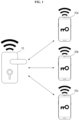
- FIG. 1 is a view illustrating an exemplary system to which an authentication method may be applied according to some embodiments of the present disclosure. Specifically, FIG. 1 illustrates an access control system.
- an exemplary access control system may include a first terminal 10 and a plurality of second terminals 20a to 20c. Although not illustrated in FIG. 1 , the exemplary access control system may further include a remote server.
- the first terminal 10 may be a device that authenticates the second terminals 20a to 20c by proximity communication and controls access to the second terminals 20a to 20c (or a user with the terminals) based on the authentication results.
- the first terminal 10 may previously register the plurality of second terminals 20a to 20c by executing a registration process, may measure a distance from the second terminals 20a to 20c via communication with the second terminals 20a to 20c disposed physically adjacent to each other, may authenticate the second terminals 20a to 20c, and may identify the second terminals 20a to 20c using previously registered information.
- the first terminal 10 may detect the second terminals 20a to 20c registered in advance to provide a function of allowing access only to registered terminals.
- the first terminal 10 may be, for example, a digital door lock that controls human access in buildings and/or houses, but the scope of the present disclosure is not limited thereto.
- the first terminal 10 may include a proximity (or short-range) communication module.
- the first terminal 10 may include one or more communication modules configured to support at least some communication technologies such as near field communication (NFC), Bluetooth (BLE), Bluetooth Low Energy (BLE), Ultra-Wide Band (UWB), and Wi-Fi.
- NFC near field communication
- BLE Bluetooth
- BLE Bluetooth Low Energy
- UWB Ultra-Wide Band
- Wi-Fi Wi-Fi
- the second terminals 20a to 20c are devices used for user access (or authentication), and may include, for example, a smart key, a smart phone, or the like. However, the scope of the present disclosure is not limited thereto.
- the reference numeral "20" is used when one of the second terminals 20a to 20c is indicated or when the plurality of second terminals 20a to 20c are collectively indicated.
- the second terminal 20 may also include a proximity (or short-range) communication module.
- the second terminal 20 may also include one or more communication modules configured to support communication technologies such as NFC, Bluetooth, BLE, UWB, and Wi-Fi.
- the second terminal 20 may further include a FIDO security authentication module.
- the authentication key may be previously shared between the first terminal 10 and the second terminal 20.
- the authentication is performed between the terminals 10 and 20 in a safe manner without establishing (using) a secure channel according to the FiRa specification. Accordingly, the authentication and access control of the second terminal 20 may be performed quickly, and the present embodiment associated therewith will be described in detail later with reference to FIG. 3 below.
- FIG. 2 is an exemplary block diagram illustrating terminals in which an authentication method is implemented according to some embodiments of the present disclosure.
- the first terminal 10 may include one or more applications 11 and an applet 12, and the second terminal 20 may also include one or more applications 21 and an applet 22.
- FIG. 2 illustrates only components associated with the embodiment of the present disclosure. Accordingly, it may be found by a person skilled in the art to which the present disclosure belongs that other universal components (e.g., a processor, a memory, and an input/output interface) may be further included in addition to the components illustrated in FIG. 2 .
- other universal components e.g., a processor, a memory, and an input/output interface
- FIG. 2 illustrates only components associated with the embodiment of the present disclosure. Accordingly, it may be found by a person skilled in the art to which the present disclosure belongs that other universal components (e.g., a processor, a memory, and an input/output interface) may be further included in addition to the components illustrated in FIG. 2 .
- the application 11 driven by the first terminal 10 may be an application in which a controller-side function defined in the FiRa specification is implemented.
- the application 11 may include a FiRa framework and/or an application using the FiRa framework.
- the application 11 may further include an application configured to implement functions according to various purposes, such as access authentication, unlocking, vehicle operation, and payment, in which the first terminal 10 is utilized.
- the application 11 may establish a communication channel (e.g., a secure channel) with another terminal, for example, the second terminal 20, via any communication module provided in the first terminal 10, and exchange data through the established communication channel.
- a communication channel e.g., a secure channel
- the applet 12 driven by the first terminal 10 may be a component that provides functions, such as UWB communication and authentication, to the application 11 of the first terminal 10.
- the applet 12 may be executed (driven) within a secure element (e.g., an embedded secure element (eSE)) of the first terminal 10.
- eSE embedded secure element
- the applet 12 may collectively refer to different kinds of applets driven by the first terminal 10.
- the applet 12 may include a FiRa applet 13 and a secure UWB service (SUS) applet 14.
- the applet 12 may further include another applet defined in the FiRa specification (or implemented in the FiRa specification).
- the FiRa applet 13 may support a variety of functions required for terminal authentication, such as authentication key generation, and a session management function for UWB communication with a counterpart terminal (e.g., the terminal 20).
- the application 21 driven by the second terminal 20 may be an application in which a controlee-side function is implemented in the FiRa specification.
- the application 21 may include a FiRa framework and/or the application using the FiRa framework.
- the application 21 may further include an application configured to implement functions according to various purposes, such as access authentication, unlocking, vehicle operation, and payment, in which the second terminal 20 is utilized.
- the application 21 may establish a communication channel (e.g., a secure channel) with another terminal, for example, the first terminal 10, via any communication module provided in the second terminal 20 and exchange data via the established communication channel.
- a communication channel e.g., a secure channel
- the applet 22 driven by the second terminal 20 may be a component that provides functions, such as UWB communication and authentication, to the application 21 of the second terminal 20.
- the applet 22 may be executed (driven) within the secure element of the second terminal 20, but the scope of the present disclosure is not limited thereto.
- the applet 22 may collectively refer to different kinds of applets driven by the second terminal 20.
- the applet 22 may also include a FiRa applet 23 and a SUS applet 24, and the applet 22 may further include another applet defined in the FiRa specification (or configured to implement a function defined in the FiRa specification).
- the second terminal 20 may further include an applet other than the applet 22.
- a further description of the applet 22 will be additionally referenced in the description of the applet 12 of the first terminal 10.
- the present inventors have devised a method capable of previously sharing an authentication key (i.e., a key used for UWB ranging-based authentication) between the terminals and quickly and safely performing authentication using the pre-shared authentication key and a random value without establishing the secure channel.
- an authentication key i.e., a key used for UWB ranging-based authentication
- the present inventors have designed an authentication method in a form that the method can be easily reflected in the current FiRa specification such that FiRa specification-based terminals can use the designed authentication method.
- the present inventors have designed a new authentication mode to be set using an application dedicated file (ADF), and also designed the method so that authentication is performed by terminals according to the designed authentication method in the case where a setting value of the ADF is in the new authentication mode.
- ADF application dedicated file
- the newly defined authentication mode may be referred to as a "secure channel unused mode” or a "fast authentication mode.”
- the fast authentication mode may be set (added) using the extended option field of the ADF, and more specifically, the fast authentication mode may be set (added) via the field that sets a UWB session key derivation scheme (e.g., see 110: Fast authentication).
- a fast authentication mode may be set in another manner.
- the new authentication mode may be set (added) using an RFU area of the extended option field, an application data field of the ADF, or other elements other than the ADF.
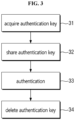
- FIG. 3 is an exemplary flowchart illustrating a schematic flow of an authentication method according to some embodiments of the present disclosure.
- the authentication method may be composed of a plurality of processes 31 to 34, for example, an authentication key acquisition process 31, an authentication key sharing process 32, an authentication process 33, and an authentication key deletion process 34.
- FIG. 3 illustrates how the processes 31 to 34 are performed sequentially, the scope of the present disclosure is not limited thereto, and the order of performing the processes 31 to 34 may vary in some cases.
- the first terminal 10 may acquire an authentication key.
- the first terminal 10 may generate the authentication key by itself or may receive the authentication key from the outside.
- the present process 31 will be described in detail later with reference to FIGS. 4 to 7 .
- the authentication key may be shared between the first terminal 10 and the second terminal 20.
- the first terminal 10 may share the authentication key by transmitting the acquired authentication key to the second terminal 20 via the secure channel.
- the secure channel between the first terminal 10 and the second terminal 20 may be established based on the FiRa specification. The present process 32 will be described in detail later with reference to FIGS. 8 to 10 .
- the authentication may be performed between the first terminal 10 and the second terminal 20.
- the first terminal 10 and the second terminal 20 may generate the session data including a session key using the shared authentication key, and may perform UWB ranging-based authentication using the generated session data.
- the present process 33 will be described in detail later with reference to FIGS. 11 to 14 .
- the authentication key shared via the authentication key sharing process 32 may be deleted.
- the present process 34 will be described in detail later with reference to FIGS. 15 to 17 .
- the authentication method according to some embodiments of the present disclosure has been schematically described with reference to FIG. 3 .
- each of the process 31 to 34 constituting the authentication method will be described in detail.
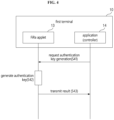
- FIG. 4 is an exemplary flowchart illustrating an authentication key acquisition process according to an embodiment of the present disclosure. However, this is only a preferred embodiment for achieving the object of the present disclosure, and some steps may be added or deleted as necessary.
- the present embodiment relates to a method in which the first terminal 10 directly generates the authentication key, and may be performed between the FiRa applet 13 and the application 11. However, the initiation of the authentication key acquisition process may be performed by an external request.
- the present embodiment may begin at a step S41 in which the application 11 transmits an authentication key generation request.
- the application 11 may transmit an authentication key generation request message to the FiRa applet 13 driven in the secure element.
- the authentication key generation request may be implemented, for example, via a "GET DATA" command (or message) (e.g., a command Application Protocol Data Unit (APDU) message) specified in the FiRa specification.
- APDU Application Protocol Data Unit
- the "GET DATA" command e.g., a command for reading the authentication key in a predefined authentication key storage area
- the FiRa applet 13 may be implemented to generate the authentication key.
- "transmission of the request” may mean an operation of transmission of the request message.
- a step S42 in response to a received request, the FiRa applet 13 may generate the authentication key.
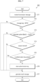
- a detailed process of the present step is illustrated in FIG. 5
- the authentication key generation step S42 may begin when the FiRa applet 13 receives the authentication key generation request message (S51).
- the FiRa applet 13 may check a tag of the authentication key request message. For example, the FiRa applet 13 may check whether the tag of the received request message is an application data tag. In FIG. 5 , because a value of the application data tag defined in the FiRa specification is "0xBF76," the tag of the message is compared with "0xBF76.”
- the FiRa applet 13 may determine whether a current authentication mode is the fast authentication mode (i.e., a secure channel unused mode) by using the extended option field of the ADF.
- the fast authentication mode is defined as "110" (a value of 8-6 bits) (see Table 1), the value of the second byte becomes "0xC0.”
- the fast authentication mode is defined in another way (e.g., in the case of using different values or other fields)
- the present step may also be modified accordingly.
- the FiRa applet 13 may determine whether the authentication key is present. For example, the FiRa applet 13 may determine whether the authentication key is present in a certain field (i.e., a predefined authentication key area) of the ADF using an instance UID (Unique IDentifier) of the ADF.
- the predefined authentication key area may be, for example, the application data field of the ADF, but the scope of the present disclosure is not limited thereto.
- a step S55 may occur.
- the FiRa applet 13 may generate the authentication key.
- the FiRa applet 13 may generate the authentication key using a random value generation algorithm or a key generation algorithm widely known in the art to which the present disclosure belongs.
- the generated authentication key may be stored in the application data field of the ADF, or may be stored in an encrypted state to improve security.
- the generated authentication key may be stored in the encrypted state by an encryption key for the secure channel that is pre-shared according to the FiRa specification.
- the FiRa applet 13 may generate a message indicating performance results.
- the FiRa applet 13 may generate an error message according to the performance results (e.g., a message tag mismatch, an authentication mode mismatch, etc.), or a result message including the generated authentication key or a pre-stored authentication key.
- the authentication key may be included in the result message in the encrypted state by the encryption key to improve security.
- the authentication key may be encrypted with the encryption key for the secure channel.
- Table 2 illustrates a format of the result message that may be generated in the step S56 described above.
- Table 2 Tag Length Description Presence 0x7A Variable Add key data mandatory 0x80 1 to 16 Instance UID Mandatory 0x81 1 Status Mandatory 0x82 16 Key data (Encrypted) mandatory
- the FiRa applet 13 may check whether the secure channel is established (e.g., it may check whether the secure channel is established with an external terminal when the authentication key acquisition process is initiated by a request of the external terminal) in some cases, and when the secure channel is found not to be established, the FiRa applet 13 may stop the authentication key generation process and generate an error message.
- the FiRa applet 13 may transmit an authentication key generation result to the application 11.
- the FiRa applet 13 may transmit the result message generated in the aforementioned step S56 to the application 11.
- the transmission of such a result message may be implemented, for example, with a "GET DATA RESPONSE" command defined in the FiRa specification.
- "transmission of the result” may mean an operation of transmission of the result message.
- FIG. 6 is an exemplary flowchart illustrating the authentication key acquisition process according to another embodiment of the present disclosure. However, this is only a preferred embodiment for achieving the object of the present disclosure, and some steps may be added or deleted as necessary.
- the present embodiment relates to a method in which the first terminal 10 receives an authentication key from the outside, and may be performed between the FiRa applet 13 and the application 11.
- the present embodiment may begin at step S61 in which the application 11 receives the authentication key from the outside.
- the secure channel may be established between the first terminal 10 and the outside in a manner defined in the FiRa specification.
- the application 11 may transmit the authentication key to the FiRa applet 13.
- the transmission of the authentication key may be implemented, for example, with a "PUT DATA" command defined in the FiRa specification.
- the scope of the present disclosure is not limited thereto.
- the FiRa applet 13 may store the authentication key.
- a detailed process of the present step is illustrated in FIG. 7 .
- an authentication key storage step S63 may begin when the FiRa applet 13 receives an authentication key transmission message (S71).
- a format of the authentication key transmission message may be designed, for example, as illustrated in Table 3 below, but the scope of the present disclosure is not limited thereto.
- the key data means the authentication key. [Table 3] Tag Length Description Presence 0xBF76 Variable Application data tag Mandatory 0x7A Variable Add key data Mandatory 0x80 1 to 16 Instance UID Mandatory 0x81 1 Status Mandatory 0x82 16 Key data (Encrypted) Mandatory
- the FiRa applet 13 may check the tag of the authentication key transmission message. For example, the FiRa applet 13 may check whether the tag of the received transmission message is an application data tag.
- the FiRa applet 13 may determine whether the current authentication mode is the fast authentication mode by using the setting value in the extended option field of the ADF.
- the FiRa applet 13 may check whether the secure channel is established with the outside.
- the FiRa applet 13 may determine whether the authentication key is present. For example, the FiRa applet 13 may determine whether the authentication key is present in the application data field of the ADF using the instance UID of the authentication key transmission message. In response to determining that the authentication key fails to be present, a step S76 may occur.
- the FiRa applet 13 may store the authentication key.
- the FiRa applet 13 may store the authentication key received in the application data field of the ADF.
- the FiRa applet 13 may store the authentication key in the encrypted state to improve security.
- the authentication key may be encrypted using the encryption key for the secure channel.
- the FiRa applet 13 may store the received authentication key. For example, the FiRa applet 13 may update (replace) the existing (stored) authentication key with the received authentication key.
- the FiRa applet 13 may generate a message indicating the performance results.
- the FiRa applet 13 may generate the error message (e.g., a message tag mismatch, an authentication mode mismatch, the presence of the authentication key, the non-establishment of the secure channel, etc.), or the result message including the stored authentication key, according to the performance results.
- the authentication key may be included in the result message in the encrypted state by the encryption key to improve security.
- the authentication key may be encrypted with the encryption key for the secure channel.
- a format of the result message that may be generated in the step S77 may be designed, for example, as illustrated in Table 4 below. However, the scope of the present disclosure is not limited thereto. [Table 4] Tag Length Description Presence 0x7A Variable Add key data mandatory 0x80 1 to 16 Instance UID Mandatory 0x81 1 Status Mandatory 0x82 16 Key data (Encrypted) mandatory
- the FiRa applet 13 may transmit an authentication key storage result to the application 11.
- the FiRa applet 13 may transmit the result message generated in the step S77 described above to the application 11.
- the authentication key acquisition process 31 has been described with reference to FIGS. 4 to 7 .
- the authentication key sharing process 32 according to some embodiments of the present disclosure will be described in detail with reference to FIGS. 8 to 10 .
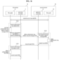
- FIG. 8 is an exemplary flowchart illustrating the authentication key sharing process 32 according to some embodiments of the present disclosure. However, this is only a preferred embodiment for achieving the object of the present disclosure, and some steps may be added or deleted as necessary.
- the authentication key sharing process 32 may begin at a step S81 of establishing the secure channel between the first terminal 10 and the second terminal 20.
- a step S81 of establishing the secure channel between the first terminal 10 and the second terminal 20 may be further performed.
- a step of setting a UWB environment between the first terminal 10 and the second terminal 20 according to the FiRa specification may be further performed.
- the FiRa specification for a detailed process of setting the UWB environment.
- the first terminal 10 may generate an authentication key sharing message.
- the authentication key sharing message may include, for example, the authentication key and the UID of the ADF.
- the scope of the present disclosure is not limited thereto.
- a detailed process of the present step is illustrated in FIG. 9 .
- the FiRa applet 13 may generate the authentication key sharing message in response to an authentication key sharing request of the application 11 and transmit the generated message to the application 11 (S91 to S93).
- the authentication key may be included in the authentication key sharing message in the encrypted state by the encryption key to improve security.
- the authentication key may be encrypted with the encryption key for the secure channel.
- the authentication key sharing request may be implemented, for example, with "TUNNEL” and “PUT DATA” commands as defined in the FiRa specification, and an authentication key sharing message transmission may be implemented with a "DISPATCH RESPONSE” command as defined in the FiRa specification.
- TUNNEL and "PUT DATA” commands as defined in the FiRa specification
- DISPATCH RESPONSE as defined in the FiRa specification.
- the scope of the present disclosure is not limited thereto.
- a format of the authentication key sharing message that may be generated in a step S92 may be designed, for example, as illustrated in Table 5 below. However, the scope of the present disclosure is not limited thereto.
- Table 5 Tag Length Description Presence 0xBF76 Variable Application data tag Mandatory 0x7A Variable Add key data Mandatory 0x80 1 to 16 Instance UID Mandatory 0x81 1 Status Mandatory 0x82 16 Key data (Encrypted) mandatory
- the first terminal 10 may transmit the authentication key sharing message to the second terminal 20.
- the transmission of the authentication key sharing message may be implemented, for example, with a "DISPATCH REQUEST" command defined in the FiRa specification.
- the scope of the present disclosure is not limited thereto.
- the second terminal 20 may receive the authentication key sharing message and store the authentication key included in the message.
- a detailed process of the present step is illustrated in FIG. 9 .
- the application 21 may receive the authentication key sharing message and transmit the authentication key to the FiRa applet 23, and the FiRa applet 23 may store the authentication key and transmit the stored result to the application 21 (S94 to S96).
- the transmission of the authentication key storage result may be implemented for example, with the "DISPATCH RESPONSE" command defined in the FiRa specification.
- the scope of the present disclosure is not limited thereto.
- step S95 A detailed process of the step S95 is illustrated in FIG. 10 .
- an authentication key storage step S95 may begin when the FiRa applet 23 receives the authentication key sharing message (S101).
- a format of the authentication key sharing message may be designed, for example, as illustrated in Table 6 below, but the scope of the present disclosure is not limited thereto.
- the key data means the authentication key. [Table 6] Tag Length Description Presence 0xBF76 Variable Application data tag Mandatory 0x7A Variable Add key data Mandatory 0x80 1 to 16 Instance UID Mandatory 0x81 1 Status Mandatory 0x82 16 Key data (Encrypted) Mandatory
- the FiRa applet 23 may check the tag of the authentication key sharing message. For example, the FiRa applet 23 may check whether the tag of the received shared message is the application data tag.
- the FiRa applet 23 may determine whether the current authentication mode is the fast authentication mode by using the setting value of the extended option field of the ADF.
- the FiRa applet 23 may check whether the secure channel is established with the first terminal 10.
- the FiRa applet 23 may determine whether the authentication key is present. For example, the FiRa applet 23 may determine whether the authentication key is present in the application data field of the ADF using the instance UID of the authentication key sharing message. In response to determining that the authentication key fails to be present, a step S 106 may occur.
- the FiRa applet 23 may store the authentication key.
- the FiRa applet 23 may store a received authentication key in the application data field of the ADF.
- the FiRa applet 23 may store the received authentication key. For example, the FiRa applet 23 may update (replace) the existing (stored) authentication key with the received authentication key.
- the FiRa applet 23 may generate the message indicating the performance results.
- the FiRa applet 23 may generate the error message (e.g., a message tag mismatch, an authentication mode mismatch, the presence of the authentication key, the non-establishment of the secure channel, etc.), or the result message including the stored authentication key, according to the performance results.
- the authentication key may be included in the result message in the encrypted state by the encryption key to improve security.
- the authentication key may be encrypted with the encryption key for the secure channel.
- a format of the result message that may be generated in the step S107 may be designed, for example, as illustrated in Table 7 below. However, the scope of the present disclosure is not limited thereto. [Table 7] Tag Length Description Presence 0x7A Variable Add key data mandatory 0x80 1 to 16 Instance UID Mandatory 0x81 1 Status Mandatory 0x82 16 Key data (Encrypted) mandatory
- the second terminal 20 may transmit the authentication key storage result to the first terminal 10.
- the application 21 of the second terminal 20 may transmit the result message generated in a step S96 to the application 11 of the first terminal 10.
- the transmission of the authentication key storage result may be implemented, for example, with the "DISPATCH REQUEST" command defined in the FiRa specification.
- the scope of the present disclosure is not limited thereto.
- the authentication key sharing process 32 has been described with reference to FIGS. 8 to 10 .
- the authentication key may be securely shared between the terminals 10 and 20 through a secure channel.
- the authentication key may be shared in the encrypted state using the encryption key for a pre-shared secure channel, thus more safely sharing the authentication key between the terminals 10 and 20.
- the authentication may be quickly performed between terminals 10 and 20 without establishing the secure channel during actual authentication by using the shared authentication key.
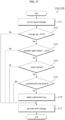
- FIG. 11 is an exemplary flowchart illustrating an authentication process 33 according to some embodiments of the present disclosure. However, this is only a preferred embodiment for achieving the object of the present disclosure, and some steps may be added or deleted as necessary.
- the authentication process 33 may begin at a step S111 in which the first terminal 10 generates session basic information.
- the session basic information is information that underlies generation of session data (or information used to generate the session data), and may include, for example, the instance UID of an ADF and the random value.
- the present disclosure is not limited thereto.
- the FiRa applet 13 may generate the session basic information in response to a request of the application 11 and transmit the generated session basic information to the application 11 (S121 to S123).
- the request for generating session basic information may be implemented, for example, with the "GET DATA" command defined in the FiRa specification.
- the scope of the present disclosure is not limited thereto.
- a detailed process of a step S122 is illustrated in FIG. 13 .
- a session basic information generation step S122 may begin when the FiRa applet 13 receives the request message (S131).
- the FiRa applet 13 may check the tag of the received request message. In other words, the FiRa applet 13 may check whether the tag value of the received request message matches a predefined tag value of a session basic information-related message.
- FIG. 13 illustrates that the predefined tag value is "0xDA30", but the value may be changed arbitrarily.
- the FiRa applet 13 may generate the session basic information including the random value.
- the session basic information may include the random value, and the instance UID of the ADF (that is, an ADF at a controller).
- the FiRa applet 13 may generate the message indicating the performance results.
- the FiRa applet 13 may generate the error message according to the performance results (e.g., a message tag mismatch, etc.), or may generate the result message including the session basic information, according to the performance results.
- a format of the result message that may be generated in the step S134 may be designed, for example, as illustrated in Table 8 below. However, the scope of the present disclosure is not limited thereto.
- Table 8 Tag Length Description Presence 0xDA30 Variable Fast authentication session basic info mandatory 0x80 Variable Instance UID of controller mandatory 0x81 Variable Random value mandatory
- the first terminal 10 may transmit the generated session basic information to the second terminal 20.
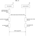
- each of the first terminal 10 and the second terminal 20 may generate the session data based on the session basic information.
- the session data may include, for example, a session ID, a session key, and a sub-session key, as defined in the FiRa specification.
- the scope of the present disclosure is not limited thereto.
- the FiRa applets 13 and 23 may generate session data in response to the request of the applications 11 and 21 and transmit the generated session data to the applications 11 and 21 (S124-1 to S126-1, and S124-2 to S126-2).
- the request for generation of the session data may be implemented, for example, with the "PUT DATA" command and a "TERMINATE SESSION" message, as defined in the FiRa specification, but the scope of the present disclosure is not limited thereto.
- steps S125-1 and S125-2 are illustrated in FIG. 14 .
- the session data generation step S125-2 (or S125-1) may begin when the FiRa applet 23 receives the request message (S141).
- the FiRa applet 23 may check the tag of the received request message. Specifically, the FiRa applet 23 may check whether the tag of the received request message is a session data tag. In FIG. 15 , because a value of the session data tag defined in the FiRa specification is "0xBF78", the tag of the request message is compared with "0xBF78.”
- a format of the request message that may be received in a step S 141 may be designed, for example, as illustrated in Table 9 below. However, the scope of the present disclosure is not limited thereto. Refer to the FiRa specification for the detailed descriptions of each field in Table 9 below.
- Table 9 Tag Length Description Presence 0xBF78 Variable Session info Mandatory 0xA5 Variable Secure ranging info Mandatory 0x80 Variable UWB_SESSION_KEY_INFO (InstanceUID
- the FiRa applet 23 may determine whether the current authentication mode is the fast authentication mode by using the setting value of the extended option field of the ADF.
- the FiRa applet 23 may generate the session data including the session key.
- the session data may be data for UWB ranging as defined in the FiRa specification.
- the FiRa applet 23 may acquire the authentication key from the application data field of the ADF using the ADF instance UID of the received session basic information, and may generate the session data (e.g., a session ID, a session key, and a sub-session key) using the acquired authentication key, the instance UID of the ADF, and the random value.
- the session data e.g., a session ID, a session key, and a sub-session key
- a specific method of generating the session data may vary according to embodiments.
- the FiRa applet 23 may generate encryption data by encrypting the instance UID of the ADF and the random value with the authentication key, and may derive the session ID and the session key from the generated encryption data.
- a portion (e.g., 0-4 bytes) of the encryption data may be a session ID
- a hash value of the encryption data may be the session key.
- the scope of the present disclosure is not limited thereto. According to the present embodiment, since the session ID and the session key are generated using the pre-shared authentication key and the random value, the security of UWB ranging-based authentication may be sufficiently ensured even if the secure channel is not established.
- the FiRa applet 23 may further generate the session data by using the encryption key for a pre-shared secure channel.
- the FiRa applet 23 may generate the encryption data by using the encryption key for the secure channel as an initial vector and encrypting the instance UID of the ADF and the random value with the authentication key (e.g., encryption using an AES algorithm).
- the FiRa applet 23 may derive the session ID and the session key from the encryption data generated in a manner similar to the previous embodiment. Therefore, the security of UWB ranging-based authentication may be further improved.
- the FiRa applet 23 may generate the message indicating the performance results.
- the FiRa applet 23 may generate the error message (e.g., a message tag mismatch, an authentication mode mismatch, etc.), or may generate the result message including the session data, according to the performance results.
- the error message e.g., a message tag mismatch, an authentication mode mismatch, etc.
- each of the first terminal 10 and the second terminal 20 may set data for UWB ranging based on the generated session data.
- the ranging data may include, for example, the session data as defined in the FiRa specification. However, the scope of the present disclosure is not limited thereto.
- the FiRa applets 13 and 23 may transmit ranging data to SUS applets 14 and 24 in response to the request of the applications 11 and 21, leading to setting the ranging data (S127-1 and S128-1, and S127-2 and S128-2).
- a request for generation the ranging data may be implemented, for example, with a "PUT DATA" command defined in the FiRa specification.
- the scope of the present disclosure is not limited thereto. Refer also to the FiRa specification for setting the ranging data.
- the UWB ranging may be performed between the first terminal 10 and the second terminal 20.
- the FiRa specification for a detailed process of the UWB ranging.
- the authentication process 33 has been described with reference to FIGS. 11 to 14 .
- the session key for the UWB ranging may be safely generated using the pre-shared authentication key and the random value. Accordingly, the authentication may be performed between the terminals 10 and 20 in a safe manner without using (establishing) the secure channel, and the time taken for authentication may be significantly reduced. In addition, the power consumed during the authentication may be minimized.
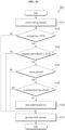
- FIG. 15 is an exemplary flowchart illustrating the authentication key deletion process 34 according to some embodiments of the present disclosure. However, this is only a preferred embodiment for achieving the object of the present disclosure, and some steps may be added or deleted as necessary.
- the authentication key deletion process 34 may being at a step S151 of establishing the secure channel between the first terminal 10 and the second terminal 20.
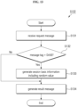
- the first terminal 10 may generate the authentication key deletion request message.
- a detailed process of the present step is illustrated in FIG. 16 .
- the FiRa applet 13 may generate the authentication key deletion request message including the instance UID of the ADF (i.e., the controller-side ADF to be deleted) in response to the authentication key deletion request of the application 11, and may transmit the generated message to the application 11 (S161 to S163).
- the authentication key deletion request may be implemented, for example, with the "TUNNEL” and “PUT DATA" commands specified in the FiRa specification, and the transmission of the authentication key deletion request message may be implemented with the "DISPATCH RESPONSE" command specified in the FiRa specification.
- the scope of the present disclosure is not limited thereto.
- the first terminal 10 may transmit the authentication key deletion request message to the second terminal 20.
- the second terminal 20 may delete the authentication key.
- a detailed process of the present step is illustrated in FIG. 16 .
- the FiRa applet 23 may delete the authentication key in response to the authentication key deletion request (e.g., reception of the authentication key deletion request message) of the application 21, and may transmit the deletion result to the application 21 (S164 to S166).
- the transmission of the deletion result may be implemented, for example, with the "DISPATCH RESPONSE" command defined in the FiRa specification.
- the scope of the present disclosure is not limited thereto.
- step S165 A detailed process of the step S165 is illustrated in FIG. 17 .
- an authentication key deletion step S165 may begin at a step S171 in which the FiRa applet 23 receives the request message from the application 21.
- the FiRa applet 23 may receive the authentication key deletion request message including a key data deletion tag and the instance UID of the ADF.
- a format of the request message that may be received in step S171 may be designed, for example, as illustrated in Table 10 below.
- Table 10 the value of "0x7B" is a tag value of a newly defined message in association with the authentication key deletion process, and the value may be changed arbitrarily.
- Table 10 Tag Length Description Presence 0xBF76 Variable Application data tag Mandatory 0x7B Variable Delete key data Mandatory 0x80 1 ⁇ 16 Instance UID Mandatory
- the FiRa applet 23 may check the tag of the received request message. For example, the FiRa applet 23 may check whether the tag of the received request message is the application data tag.
- the FiRa applet 23 may determine whether the current authentication mode is the fast authentication mode by using the setting value of the extended option field of the ADF.
- the FiRa applet 23 may check whether the secure channel is established with the first terminal 10.
- the FiRa applet 23 may determine whether the authentication key is present. For example, the FiRa applet 23 may determine whether the authentication key is present in the application data field of the ADF using the instance UID of the ADF included in the authentication key deletion request message. In response to determining that the authentication key is present, a step S176 may occur.
- the FiRa applet 23 may delete the authentication key. In other words, the FiRa applet 23 may delete the authentication key stored in the application data field of the ADF.
- the FiRa applet 23 may generate the message indicating the performance results.
- the FiRa applet 23 may generate the error message (e.g., a message tag mismatch, an authentication mode mismatch, the non-presence of the authentication key, the non-establishment of the secure channel, etc.), or may generate result message notifying the success of the deletion, according to the performance results.
- the error message e.g., a message tag mismatch, an authentication mode mismatch, the non-presence of the authentication key, the non-establishment of the secure channel, etc.
- the second terminal 20 may transmit the result of deleting the authentication key to the first terminal 10.
- step S156 the first terminal 10 may also delete the authentication key.
- the present step is similar to the step S154 described above, and a description thereof will be omitted herein (refer to steps S164 to S166 for the description of steps S167 to S169).
- a method capable of confirming an ADF list managed by the FiRa applet fails to be defined, and when the instance UID is not known, the presence or absence of a certain ADF cannot be determined. For example, when the instance UID is not known, the presence or absence of the certain ADF may not be determined using a "SELECT ADF" command. Accordingly, a command (or message) capable of acquiring a list of ADFs managed by the FiRa applet (e.g., 13) needs to be additionally defined.
- Such a command may be easily implemented with a command of "GET DATA” and a new tag value (e.g., "0xBFAD”) associated with ADF information, and a response message to the corresponding command may be designed, for example, as described in Table 11.
- a command of "GET DATA” and a new tag value e.g., "0xBFAD”
- a response message to the corresponding command may be designed, for example, as described in Table 11.
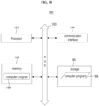
- an exemplary computing device 180 capable of implementing the first terminal 10 and/or the second terminal 20 described above will be briefly described with reference to FIG. 18 .
- FIG. 18 illustrates a diagram illustrating a hardware configuration of the computing device 180.
- the computing device 180 may include one or more processors 181, a bus 183, a communication interface 182, a memory 184 configured to load a computer program 186 performed by the processor 181, and a storage 185 configured to store the computer program 186.
- the processor 181 may control an overall operation of each component of the computing device 180.
- the processor 181 may include at least one of a central processing unit (CPU), a micro-processor unit (MPU), a micro-controller unit (MCU), a graphical processing unit (GPU), or any type of processor known in the technical field of the present disclosure.
- the processor 181 may perform an arithmetic operation on at least one applet, application, and/or program for the purpose of executing the method/operation according to various embodiments of the present disclosure.
- the computing device 180 may include one or more processors 181.
- the memory 184 may store different kinds of data, instructions, and/or information.
- the memory 184 may load one or more computer programs 186 from storage 185 to execute method/operations according to various embodiments of the present disclosure.
- An example of the memory 184 may be a RAM, but the present invention is not limited thereto.
- the bus 183 may provide a communication function between components of the computing device 180.
- the bus 183 may be implemented as various types of buses such as an address bus, a data bus, and a control bus.
- the communication interface 182 may support wired or wireless communication of the computing device 180.
- the communication interface 182 may support various types of proximity communication, and may further support a variety of communication methods.
- the communication interface 182 may include a communication module known in the technical field of the present disclosure.
- the storage 185 may non-temporarily store one or more computer programs 186.
- the storage 185 may include a non-volatile memory such as a flash memory, a hard disk, a removable disk, or any type of computer-readable recording medium known in the technical field to which the present disclosure belongs.
- the computer program 186 may include one or more instructions in which methods/operations according to a variety of embodiments of the present disclosure are implemented.
- the processor 181 may perform the methods/operations according to a variety of embodiments of the present disclosure by executing the loaded instructions.
- the computer program 186 may include the instructions implementing the operations of the application 11 and the applet 12.
- the first terminal 10 according to some embodiments of the present disclosure may be implemented with the computing device 180.
- the computer program 186 may include instructions implementing operations of the application 21 and the applet 22.
- the second terminal 20 according to some embodiments of the present disclosure may be implemented with the computing device 180.
- the exemplary computing device 180 capable of implementing the terminals 10 and 20 according to some embodiments of the present disclosure has been described with reference to FIG. 18 .
- the technical features of the present disclosure described so far may be embodied as computer readable codes on a computer readable medium.
- the computer readable medium may be, for example, a removable recording medium (CD, DVD, Blu-ray disc, USB storage device, removable hard disk) or a fixed recording medium (ROM, RAM, computer equipped hard disk).
- the computer program recorded on the computer readable medium may be transmitted to other computing device via a network such as internet and installed in the other computing device, thereby being used in the other computing device.
Landscapes
- Engineering & Computer Science (AREA)
- Computer Networks & Wireless Communication (AREA)
- Computer Security & Cryptography (AREA)
- Signal Processing (AREA)
- Radar, Positioning & Navigation (AREA)
- Remote Sensing (AREA)
- Physics & Mathematics (AREA)
- General Physics & Mathematics (AREA)
- Mobile Radio Communication Systems (AREA)
- Storage Device Security (AREA)
Claims (20)
- Authentifizierungsverfahren in einem ungenutzten Modus eines sicheren Kanals auf einem ersten Endgerät (10), in dem ein Fine Ranging, FiRa, Applet (13) ausgeführt wird, wobei das Verfahren umfasst:Erzeugen (S111) von Sitzungsbasisinformationen, die einen Zufallswert umfassen;Senden (S112) der erzeugten Sitzungsbasisinformationen an ein zweites Endgerät (20), ohne einen sicheren Kanal mit dem zweiten Endgerät (20) einzurichten;Erzeugen (S113-1) von Sitzungsdaten, die einen Sitzungsschlüssel umfassen, aus den erzeugten Sitzungsbasisinformationen unter Verwendung eines Authentifizierungsschlüssels, der vorab mit dem zweiten Endgerät (20) geteilt wurde; undDurchführen (S115) einer Ultrabreitband-, UWB, Entfernungsbestimmung (Ranging) mit dem zweiten Endgerät (20) unter Verwendung der erzeugten Sitzungsdaten.
- Authentifizierungsverfahren nach Anspruch 1, wobei die Sitzungsbasisinformationen ferner eine Instanz-eindeutige Kennung, Instanz-UID, einer anwendungsspezifischen Datei, ADF (Application Dedicated File), umfassen.
- Authentifizierungsverfahren nach Anspruch 2, wobei das Erzeugen (S111) der Sitzungsdaten umfasst:Erzeugen von Verschlüsselungsdaten durch Verschlüsseln des Zufallswerts und der Instanz-UID mit dem Authentifizierungsschlüssel; undAbleiten des Sitzungsschlüssels aus den Verschlüsselungsdaten.
- Authentifizierungsverfahren nach Anspruch 3, wobei das Erzeugen (S111) der Verschlüsselungsdaten Erzeugen der Verschlüsselungsdaten durch weiteres Verwenden eines Verschlüsselungsschlüssels für einen vorab gemeinsam genutzten sicheren Kanal umfasst.
- Authentifizierungsverfahren nach Anspruch 2, wobei die Sitzungsdaten ferner eine Sitzungs-ID umfassen, und
das Erzeugen (S113-1) der Sitzungsdaten umfasst:Erzeugen von Verschlüsselungsdaten durch Verschlüsseln des Zufallswerts und der Instanz-UID mit dem Authentifizierungsschlüssel; undAbleiten der Sitzungs-ID aus den Verschlüsselungsdaten. - Authentifizierungsverfahren nach Anspruch 1, wobei das Erzeugen (S113-1) der Sitzungsdaten umfasst:Bestimmen eines aktuellen Authentifizierungsmodus unter Verwendung eines Einstellwerts in einem Feld einer anwendungsdokumentierten Datei, ADF; undals Reaktion auf ein Bestimmen, dass der aktuelle Authentifizierungsmodus der ungenutzte Modus des sicheren Kanals ist, Erzeugen der Sitzungsdaten.
- Authentifizierungsverfahren nach Anspruch 6, wobei das Feld ein erweitertes Optionsfeld der ADF ist.
- Authentifizierungsverfahren in einem ungenutzten Modus eines sicheren Kanals auf einem zweiten Endgerät (20), in dem ein Fine Ranging, FiRa, Applet (23) ausgeführt wird, wobei das Verfahren umfasst:Empfangen (S112) von Sitzungsbasisinformationen, die einen Zufallswert umfassen, von einem ersten Endgerät (10), ohne einen sicheren Kanal mit dem ersten Endgerät (10) einzurichten;Erzeugen (S113-2) von Sitzungsdaten, die einen Sitzungsschlüssel umfassen, aus den empfangenen Sitzungsbasisinformationen unter Verwendung eines Authentifizierungsschlüssels, der vorab mit dem ersten Endgerät (10) geteilt wurde; undDurchführen (S115) einer Ultrabreitband-, UWB, Entfernungsmessung (Ranging) mit dem ersten Endgerät (10) unter Verwendung der erzeugten Sitzungsdaten.
- Authentifizierungsverfahren nach Anspruch 8, wobei die Sitzungsbasisinformationen ferner eine Instanz-eindeutige Kennung, Instanz-UID, einer anwendungsspezifischen Datei, ADF, umfassen;ein Authentifizierungsschlüssel in einem bestimmten Feld der ADF gespeichert wird; unddas Erzeugen (S113-2) der Sitzungsdaten umfasst:Erwerben des Authentifizierungsschlüssels vor Ort unter Verwendung der in den Sitzungsbasisinformationen enthaltenen Instanz-UID; undErzeugen der Sitzungsdaten unter Verwendung des Authentifizierungsschlüssels.
- Authentifizierungsverfahren nach Anspruch 8, wobei das Erzeugen (S 113-2) der Sitzungsdaten umfasst:Bestimmen (S 143) eines aktuellen Authentifizierungsmodus unter Verwendung eines Einstellwerts in einem Feld einer anwendungsdokumentierten Datei, ADF; undals Reaktion auf ein Bestimmen, dass der aktuelle Authentifizierungsmodus der ungenutzte Modus des sicheren Kanals ist, Erzeugen der Sitzungsdaten.
- Authentifizierungsverfahren nach Anspruch 1, ferner umfassend:Erwerben (31) des Authentifizierungsschlüssels;Speichern des erworbenen Authentifizierungsschlüssels in einem ersten Feld einer anwendungsspezifischen Datei, ADF;Teilen des erworbenen Authentifizierungsschlüssels mit dem zweiten Endgerät über einen sicheren Kanal.
- Authentifizierungsverfahren nach Anspruch 11, wobei das erste Feld ein Anwendungsdatenfeld der ADF ist.
- Authentifizierungsverfahren nach Anspruch 11, wobei das Erwerben (31) des Authentifizierungsschlüssels Erzeugen (S42) des Authentifizierungsschlüssels durch das FiRa-Applet (13) umfasst.
- Authentifizierungsverfahren nach Anspruch 13, wobei das Erwerben (31) des Authentifizierungsschlüssels umfasst:Bestimmen (S54), ob ein vorab gespeicherter Authentifizierungsschlüssel in dem ersten Feld vorhanden ist, unter Verwendung einer Instanz-eindeutigen Kennung, UID, der ADF; undals Reaktion auf ein Bestimmen, dass der vorab gespeicherte Authentifizierungsschlüssel nicht vorhanden ist, Erzeugen des Authentifizierungsschlüssels.
- Authentifizierungsverfahren nach Anspruch 13, wobei das Erzeugen (S42) des Authentifizierungsschlüssels umfasst:Bestimmen (S53) eines aktuellen Authentifizierungsmodus unter Verwendung eines Einstellwerts in einem zweiten Feld der ADF; undals Reaktion auf ein Bestimmen, dass der aktuelle Authentifizierungsmodus der ungenutzte Modus des sicheren Kanals ist, Erzeugen des Authentifizierungsschlüssels.
- Authentifizierungsverfahren nach Anspruch 11, wobei das Erwerben (31) des Authentifizierungsschlüssels Empfangen (S61) des Authentifizierungsschlüssels von außen durch eine Anwendung (11), die von dem ersten Endgerät (10) ausgeführt wird, umfasst; und
das Speichern des Authentifizierungsschlüssels Speichern (S63) des von dem FiRa-Applet (13) empfangenen Authentifizierungsschlüssels umfasst. - Authentifizierungsverfahren nach Anspruch 8, ferner umfassend:Empfangen (S84) des Authentifizierungsschlüssels von einem ersten Endgerät (10) über einen sicheren Kanal; undSpeichern (S95) des empfangenen Authentifizierungsschlüssels in einem ersten Feld einer anwendungsspezifischen Datei, ADF.
- Authentifizierungsverfahren nach Anspruch 17, wobei das Speichern (S95) des Authentifizierungsschlüssels umfasst:Bestimmen (S103) eines aktuellen Authentifizierungsmodus unter Verwendung eines Einstellwerts in einem zweiten Feld der ADF; undals Reaktion auf ein Bestimmen, dass der aktuelle Authentifizierungsmodus der ungenutzte Modus des sicheren Kanals ist, Speichern des empfangenen Authentifizierungsschlüssels.
- Authentifizierungsverfahren nach Anspruch 17, wobei das zweite Endgerät (20) ferner eine Instanz-eindeutige Kennung, Instanz-UID, der ADF von dem ersten Endgerät (10) empfängt; und
das Speichern (S95) des empfangenen Authentifizierungsschlüssels umfasst:Bestimmen (S105), ob ein vorab gespeicherter Authentifizierungsschlüssel in dem ersten Feld vorhanden ist, unter Verwendung der empfangenen Instanz-UID; undals Reaktion auf ein Bestimmen, dass der vorab gespeicherte Authentifizierungsschlüssel nicht vorhanden ist, Speichern des empfangenen Authentifizierungsschlüssels. - Authentifizierungsverfahren nach Anspruch 17, ferner umfassend:Empfangen (S171) einer Anforderungsnachricht zum Löschen des Authentifizierungsschlüssels, die die Instanz-UID der ADF aufweist, von dem ersten Endgerät (10);Bestimmen (S175), ob der vorab gespeicherte Authentifizierungsschlüssel in dem ersten Feld vorhanden ist, unter Verwendung der Instanz-UID; undals Reaktion auf ein Bestimmen, dass der vorab gespeicherte Authentifizierungsschlüssel vorhanden ist, Löschen (S154) des vorab gespeicherten Authentifizierungsschlüssels.
Applications Claiming Priority (2)
| Application Number | Priority Date | Filing Date | Title |
|---|---|---|---|
| KR20210089210 | 2021-07-07 | ||
| KR1020220044980A KR20230008595A (ko) | 2021-07-07 | 2022-04-12 | 근접 통신 기능을 구비한 단말들 간의 인증 방법 및 이 방법이 구현된 단말들 |
Publications (2)
| Publication Number | Publication Date |
|---|---|
| EP4117230A1 EP4117230A1 (de) | 2023-01-11 |
| EP4117230B1 true EP4117230B1 (de) | 2025-01-29 |
Family
ID=82608414
Family Applications (1)
| Application Number | Title | Priority Date | Filing Date |
|---|---|---|---|
| EP22182495.6A Active EP4117230B1 (de) | 2021-07-07 | 2022-07-01 | Authentifizierungsverfahren zwischen endgeräten, die eine nahkommunikationsfunktion aufweisen, und endgeräten, die dieses verfahren implementieren |
Country Status (2)
| Country | Link |
|---|---|
| US (1) | US20230013613A1 (de) |
| EP (1) | EP4117230B1 (de) |
Families Citing this family (2)
| Publication number | Priority date | Publication date | Assignee | Title |
|---|---|---|---|---|
| KR20250151489A (ko) * | 2023-03-16 | 2025-10-21 | 삼성전자주식회사 | Uwb 시스템에서 디바이스 및 서비스 액세스를 관리하는 방법 및 장치 |
| US20250193157A1 (en) * | 2023-12-12 | 2025-06-12 | Nxp B.V. | System and method to control access of ultra-wideband (uwb) devices |
Family Cites Families (9)
| Publication number | Priority date | Publication date | Assignee | Title |
|---|---|---|---|---|
| US8700729B2 (en) * | 2005-01-21 | 2014-04-15 | Robin Dua | Method and apparatus for managing credentials through a wireless network |
| US9143937B2 (en) * | 2011-09-12 | 2015-09-22 | Qualcomm Incorporated | Wireless communication using concurrent re-authentication and connection setup |
| KR102124413B1 (ko) * | 2013-12-30 | 2020-06-19 | 삼성에스디에스 주식회사 | 아이디 기반 키 관리 시스템 및 방법 |
| KR20150074515A (ko) * | 2013-12-24 | 2015-07-02 | 삼성전기주식회사 | 네트워크 시스템 및 네트워킹 방법 |
| US9763063B2 (en) * | 2014-10-06 | 2017-09-12 | Derek D. Kumar | Secure broadcast beacon communications |
| CN107317674B (zh) * | 2016-04-27 | 2021-08-31 | 华为技术有限公司 | 密钥分发、认证方法,装置及系统 |
| CN109391940B (zh) * | 2017-08-02 | 2021-02-12 | 华为技术有限公司 | 一种接入网络的方法、设备及系统 |
| WO2021089195A1 (en) * | 2019-11-07 | 2021-05-14 | Assa Abloy Ab | Upper layer device architecture for ultra-wide band enabled device |
| EP3910901B1 (de) * | 2020-05-15 | 2025-03-05 | Nxp B.V. | Uwb-kommunikationsknoten und betriebsverfahren |
-
2022
- 2022-07-01 EP EP22182495.6A patent/EP4117230B1/de active Active
- 2022-07-06 US US17/858,435 patent/US20230013613A1/en not_active Abandoned
Also Published As
| Publication number | Publication date |
|---|---|
| EP4117230A1 (de) | 2023-01-11 |
| US20230013613A1 (en) | 2023-01-19 |
Similar Documents
| Publication | Publication Date | Title |
|---|---|---|
| US10925102B2 (en) | System and method for NFC peer-to-peer authentication and secure data transfer | |
| US11736937B2 (en) | UWB communication node and operating method | |
| US11991527B2 (en) | Communication method and communication device | |
| KR100881938B1 (ko) | 다중 스마트 카드 세션을 관리하는 시스템 및 방법 | |
| EP4117230B1 (de) | Authentifizierungsverfahren zwischen endgeräten, die eine nahkommunikationsfunktion aufweisen, und endgeräten, die dieses verfahren implementieren | |
| KR20200028827A (ko) | Uwb 트랜잭션을 위한 방법 및 전자 장치 | |
| US20150326442A1 (en) | Method, node, and gateway for triggering networking | |
| EP3155552B1 (de) | Mechanismen zur steuerung von etikett-personalisierung | |
| CN115669022B (zh) | 电子设备提供基于测距的服务的方法和电子设备 | |
| US11546954B2 (en) | Device and vehicle pairing using a network connection | |
| CN110278083B (zh) | 身份认证请求处理方法和装置、设备重置方法和装置 | |
| CN111935302B (zh) | 钥匙管理装置、方法和设备 | |
| CN112425116B (zh) | 智能门锁无线通信方法、智能门锁、网关及通信设备 | |
| EP4322467A1 (de) | Schlüsselverarbeitungsverfahren und -vorrichtung | |
| CN116349202A (zh) | 利用伪随机数的相互认证 | |
| CN106254304B (zh) | 用于促进安全通信的方法和系统 | |
| CN110992528A (zh) | 一种基于识别码的智能门锁绑定方法、设备及存储介质 | |
| KR20230016493A (ko) | 차량 제어 장치 그 제어 방법 | |
| KR20230008595A (ko) | 근접 통신 기능을 구비한 단말들 간의 인증 방법 및 이 방법이 구현된 단말들 | |
| CN118233869A (zh) | 配对绑定方法、装置、电子设备和可读存储介质 | |
| KR101991511B1 (ko) | 휴대용 스마트장치를 이용한 홈아이오티기반 장치의 환경설정 및 등록방법 | |
| RU2633186C1 (ru) | Персональное устройство аутентификации и защиты данных | |
| CN114760711B (zh) | 门锁接入物联网平台方法、装置、存储介质及终端设备 | |
| CN117135617A (zh) | vSIM的配置管理方法、装置、设备及存储介质 | |
| CN121284573A (zh) | 基于无线射频rssi的设备配对鉴权方法、装置和系统 |
Legal Events
| Date | Code | Title | Description |
|---|---|---|---|
| PUAI | Public reference made under article 153(3) epc to a published international application that has entered the european phase |
Free format text: ORIGINAL CODE: 0009012 |
|
| STAA | Information on the status of an ep patent application or granted ep patent |
Free format text: STATUS: EXAMINATION IS IN PROGRESS |
|
| 17P | Request for examination filed |
Effective date: 20220701 |
|
| AK | Designated contracting states |
Kind code of ref document: A1 Designated state(s): AL AT BE BG CH CY CZ DE DK EE ES FI FR GB GR HR HU IE IS IT LI LT LU LV MC MK MT NL NO PL PT RO RS SE SI SK SM TR |
|
| REG | Reference to a national code |
Ref country code: DE Ref legal event code: R079 Free format text: PREVIOUS MAIN CLASS: H04L0009400000 Ipc: H04L0009080000 Ref country code: DE Ref legal event code: R079 Ref document number: 602022009999 Country of ref document: DE Free format text: PREVIOUS MAIN CLASS: H04L0009400000 Ipc: H04L0009080000 |
|
| GRAP | Despatch of communication of intention to grant a patent |
Free format text: ORIGINAL CODE: EPIDOSNIGR1 |
|
| STAA | Information on the status of an ep patent application or granted ep patent |
Free format text: STATUS: GRANT OF PATENT IS INTENDED |
|
| RIC1 | Information provided on ipc code assigned before grant |
Ipc: G07C 9/00 20200101ALI20240322BHEP Ipc: H04W 12/069 20210101ALI20240322BHEP Ipc: H04W 12/047 20210101ALI20240322BHEP Ipc: H04W 12/041 20210101ALI20240322BHEP Ipc: H04L 9/08 20060101AFI20240322BHEP |
|
| INTG | Intention to grant announced |
Effective date: 20240422 |
|
| GRAJ | Information related to disapproval of communication of intention to grant by the applicant or resumption of examination proceedings by the epo deleted |
Free format text: ORIGINAL CODE: EPIDOSDIGR1 |
|
| STAA | Information on the status of an ep patent application or granted ep patent |
Free format text: STATUS: EXAMINATION IS IN PROGRESS |
|
| GRAP | Despatch of communication of intention to grant a patent |
Free format text: ORIGINAL CODE: EPIDOSNIGR1 |
|
| STAA | Information on the status of an ep patent application or granted ep patent |
Free format text: STATUS: GRANT OF PATENT IS INTENDED |
|
| INTC | Intention to grant announced (deleted) | ||
| INTG | Intention to grant announced |
Effective date: 20240920 |
|
| GRAS | Grant fee paid |
Free format text: ORIGINAL CODE: EPIDOSNIGR3 |
|
| GRAA | (expected) grant |
Free format text: ORIGINAL CODE: 0009210 |
|
| STAA | Information on the status of an ep patent application or granted ep patent |
Free format text: STATUS: THE PATENT HAS BEEN GRANTED |
|
| P01 | Opt-out of the competence of the unified patent court (upc) registered |
Free format text: CASE NUMBER: APP_63288/2024 Effective date: 20241128 |
|
| AK | Designated contracting states |
Kind code of ref document: B1 Designated state(s): AL AT BE BG CH CY CZ DE DK EE ES FI FR GB GR HR HU IE IS IT LI LT LU LV MC MK MT NL NO PL PT RO RS SE SI SK SM TR |
|
| REG | Reference to a national code |
Ref country code: GB Ref legal event code: FG4D |
|
| REG | Reference to a national code |
Ref country code: CH Ref legal event code: EP |
|
| REG | Reference to a national code |
Ref country code: DE Ref legal event code: R096 Ref document number: 602022009999 Country of ref document: DE |
|
| REG | Reference to a national code |
Ref country code: IE Ref legal event code: FG4D |
|
| REG | Reference to a national code |
Ref country code: NL Ref legal event code: MP Effective date: 20250129 |
|
| PG25 | Lapsed in a contracting state [announced via postgrant information from national office to epo] |
Ref country code: NL Free format text: LAPSE BECAUSE OF FAILURE TO SUBMIT A TRANSLATION OF THE DESCRIPTION OR TO PAY THE FEE WITHIN THE PRESCRIBED TIME-LIMIT Effective date: 20250129 |
|
| PG25 | Lapsed in a contracting state [announced via postgrant information from national office to epo] |
Ref country code: RS Free format text: LAPSE BECAUSE OF FAILURE TO SUBMIT A TRANSLATION OF THE DESCRIPTION OR TO PAY THE FEE WITHIN THE PRESCRIBED TIME-LIMIT Effective date: 20250429 |
|
| PG25 | Lapsed in a contracting state [announced via postgrant information from national office to epo] |
Ref country code: FI Free format text: LAPSE BECAUSE OF FAILURE TO SUBMIT A TRANSLATION OF THE DESCRIPTION OR TO PAY THE FEE WITHIN THE PRESCRIBED TIME-LIMIT Effective date: 20250129 |
|
| PG25 | Lapsed in a contracting state [announced via postgrant information from national office to epo] |
Ref country code: PL Free format text: LAPSE BECAUSE OF FAILURE TO SUBMIT A TRANSLATION OF THE DESCRIPTION OR TO PAY THE FEE WITHIN THE PRESCRIBED TIME-LIMIT Effective date: 20250129 |
|
| PG25 | Lapsed in a contracting state [announced via postgrant information from national office to epo] |
Ref country code: ES Free format text: LAPSE BECAUSE OF FAILURE TO SUBMIT A TRANSLATION OF THE DESCRIPTION OR TO PAY THE FEE WITHIN THE PRESCRIBED TIME-LIMIT Effective date: 20250129 |
|
| REG | Reference to a national code |
Ref country code: LT Ref legal event code: MG9D |
|
| PG25 | Lapsed in a contracting state [announced via postgrant information from national office to epo] |
Ref country code: NO Free format text: LAPSE BECAUSE OF FAILURE TO SUBMIT A TRANSLATION OF THE DESCRIPTION OR TO PAY THE FEE WITHIN THE PRESCRIBED TIME-LIMIT Effective date: 20250429 Ref country code: IS Free format text: LAPSE BECAUSE OF FAILURE TO SUBMIT A TRANSLATION OF THE DESCRIPTION OR TO PAY THE FEE WITHIN THE PRESCRIBED TIME-LIMIT Effective date: 20250529 |
|
| REG | Reference to a national code |
Ref country code: AT Ref legal event code: MK05 Ref document number: 1764520 Country of ref document: AT Kind code of ref document: T Effective date: 20250129 |
|
| PG25 | Lapsed in a contracting state [announced via postgrant information from national office to epo] |
Ref country code: HR Free format text: LAPSE BECAUSE OF FAILURE TO SUBMIT A TRANSLATION OF THE DESCRIPTION OR TO PAY THE FEE WITHIN THE PRESCRIBED TIME-LIMIT Effective date: 20250129 |
|
| PG25 | Lapsed in a contracting state [announced via postgrant information from national office to epo] |
Ref country code: LV Free format text: LAPSE BECAUSE OF FAILURE TO SUBMIT A TRANSLATION OF THE DESCRIPTION OR TO PAY THE FEE WITHIN THE PRESCRIBED TIME-LIMIT Effective date: 20250129 Ref country code: PT Free format text: LAPSE BECAUSE OF FAILURE TO SUBMIT A TRANSLATION OF THE DESCRIPTION OR TO PAY THE FEE WITHIN THE PRESCRIBED TIME-LIMIT Effective date: 20250529 |
|
| PG25 | Lapsed in a contracting state [announced via postgrant information from national office to epo] |
Ref country code: GR Free format text: LAPSE BECAUSE OF FAILURE TO SUBMIT A TRANSLATION OF THE DESCRIPTION OR TO PAY THE FEE WITHIN THE PRESCRIBED TIME-LIMIT Effective date: 20250430 Ref country code: BG Free format text: LAPSE BECAUSE OF FAILURE TO SUBMIT A TRANSLATION OF THE DESCRIPTION OR TO PAY THE FEE WITHIN THE PRESCRIBED TIME-LIMIT Effective date: 20250129 |
|
| PG25 | Lapsed in a contracting state [announced via postgrant information from national office to epo] |
Ref country code: AT Free format text: LAPSE BECAUSE OF FAILURE TO SUBMIT A TRANSLATION OF THE DESCRIPTION OR TO PAY THE FEE WITHIN THE PRESCRIBED TIME-LIMIT Effective date: 20250129 |
|
| PG25 | Lapsed in a contracting state [announced via postgrant information from national office to epo] |
Ref country code: SE Free format text: LAPSE BECAUSE OF FAILURE TO SUBMIT A TRANSLATION OF THE DESCRIPTION OR TO PAY THE FEE WITHIN THE PRESCRIBED TIME-LIMIT Effective date: 20250129 |
|
| PG25 | Lapsed in a contracting state [announced via postgrant information from national office to epo] |
Ref country code: SM Free format text: LAPSE BECAUSE OF FAILURE TO SUBMIT A TRANSLATION OF THE DESCRIPTION OR TO PAY THE FEE WITHIN THE PRESCRIBED TIME-LIMIT Effective date: 20250129 |
|
| PG25 | Lapsed in a contracting state [announced via postgrant information from national office to epo] |
Ref country code: DK Free format text: LAPSE BECAUSE OF FAILURE TO SUBMIT A TRANSLATION OF THE DESCRIPTION OR TO PAY THE FEE WITHIN THE PRESCRIBED TIME-LIMIT Effective date: 20250129 |
|
| PGFP | Annual fee paid to national office [announced via postgrant information from national office to epo] |
Ref country code: DE Payment date: 20250609 Year of fee payment: 4 |
|
| PG25 | Lapsed in a contracting state [announced via postgrant information from national office to epo] |
Ref country code: IT Free format text: LAPSE BECAUSE OF FAILURE TO SUBMIT A TRANSLATION OF THE DESCRIPTION OR TO PAY THE FEE WITHIN THE PRESCRIBED TIME-LIMIT Effective date: 20250129 |
|
| PG25 | Lapsed in a contracting state [announced via postgrant information from national office to epo] |
Ref country code: CZ Free format text: LAPSE BECAUSE OF FAILURE TO SUBMIT A TRANSLATION OF THE DESCRIPTION OR TO PAY THE FEE WITHIN THE PRESCRIBED TIME-LIMIT Effective date: 20250129 Ref country code: EE Free format text: LAPSE BECAUSE OF FAILURE TO SUBMIT A TRANSLATION OF THE DESCRIPTION OR TO PAY THE FEE WITHIN THE PRESCRIBED TIME-LIMIT Effective date: 20250129 |
|
| PG25 | Lapsed in a contracting state [announced via postgrant information from national office to epo] |
Ref country code: RO Free format text: LAPSE BECAUSE OF FAILURE TO SUBMIT A TRANSLATION OF THE DESCRIPTION OR TO PAY THE FEE WITHIN THE PRESCRIBED TIME-LIMIT Effective date: 20250129 |
|
| PG25 | Lapsed in a contracting state [announced via postgrant information from national office to epo] |
Ref country code: SK Free format text: LAPSE BECAUSE OF FAILURE TO SUBMIT A TRANSLATION OF THE DESCRIPTION OR TO PAY THE FEE WITHIN THE PRESCRIBED TIME-LIMIT Effective date: 20250129 |
|
| REG | Reference to a national code |
Ref country code: DE Ref legal event code: R097 Ref document number: 602022009999 Country of ref document: DE |
|
| PLBE | No opposition filed within time limit |
Free format text: ORIGINAL CODE: 0009261 |
|
| STAA | Information on the status of an ep patent application or granted ep patent |
Free format text: STATUS: NO OPPOSITION FILED WITHIN TIME LIMIT |
|
| REG | Reference to a national code |
Ref country code: CH Ref legal event code: L10 Free format text: ST27 STATUS EVENT CODE: U-0-0-L10-L00 (AS PROVIDED BY THE NATIONAL OFFICE) Effective date: 20251210 |
|
| 26N | No opposition filed |
Effective date: 20251030 |
|
| REG | Reference to a national code |
Ref country code: CH Ref legal event code: H13 Free format text: ST27 STATUS EVENT CODE: U-0-0-H10-H13 (AS PROVIDED BY THE NATIONAL OFFICE) Effective date: 20260224 |
|
| PG25 | Lapsed in a contracting state [announced via postgrant information from national office to epo] |
Ref country code: LU Free format text: LAPSE BECAUSE OF NON-PAYMENT OF DUE FEES Effective date: 20250701 |
|
| REG | Reference to a national code |
Ref country code: BE Ref legal event code: MM Effective date: 20250731 |
|
| PG25 | Lapsed in a contracting state [announced via postgrant information from national office to epo] |
Ref country code: BE Free format text: LAPSE BECAUSE OF NON-PAYMENT OF DUE FEES Effective date: 20250731 |
|
| PG25 | Lapsed in a contracting state [announced via postgrant information from national office to epo] |
Ref country code: FR Free format text: LAPSE BECAUSE OF NON-PAYMENT OF DUE FEES Effective date: 20250731 |