EP4322467A1 - Schlüsselverarbeitungsverfahren und -vorrichtung - Google Patents
Schlüsselverarbeitungsverfahren und -vorrichtung Download PDFInfo
- Publication number
- EP4322467A1 EP4322467A1 EP21938305.6A EP21938305A EP4322467A1 EP 4322467 A1 EP4322467 A1 EP 4322467A1 EP 21938305 A EP21938305 A EP 21938305A EP 4322467 A1 EP4322467 A1 EP 4322467A1
- Authority
- EP
- European Patent Office
- Prior art keywords
- key
- memory slot
- encryption information
- information
- memory
- Prior art date
- Legal status (The legal status is an assumption and is not a legal conclusion. Google has not performed a legal analysis and makes no representation as to the accuracy of the status listed.)
- Pending
Links
- 238000003672 processing method Methods 0.000 title claims abstract description 23
- 230000015654 memory Effects 0.000 claims abstract description 976
- 238000000034 method Methods 0.000 claims abstract description 146
- 238000004891 communication Methods 0.000 claims abstract description 59
- 230000007246 mechanism Effects 0.000 claims description 151
- 238000003860 storage Methods 0.000 claims description 114
- 238000012545 processing Methods 0.000 claims description 103
- 238000012546 transfer Methods 0.000 claims description 18
- 238000004590 computer program Methods 0.000 claims description 14
- 230000008569 process Effects 0.000 abstract description 55
- 238000005516 engineering process Methods 0.000 abstract description 5
- 230000006870 function Effects 0.000 description 43
- 238000012795 verification Methods 0.000 description 39
- VIEYMVWPECAOCY-UHFFFAOYSA-N 7-amino-4-(chloromethyl)chromen-2-one Chemical compound ClCC1=CC(=O)OC2=CC(N)=CC=C21 VIEYMVWPECAOCY-UHFFFAOYSA-N 0.000 description 20
- 239000003795 chemical substances by application Substances 0.000 description 12
- 238000010586 diagram Methods 0.000 description 9
- 230000003287 optical effect Effects 0.000 description 9
- 230000008859 change Effects 0.000 description 7
- 238000007726 management method Methods 0.000 description 7
- 238000012423 maintenance Methods 0.000 description 4
- 230000003068 static effect Effects 0.000 description 4
- 230000004913 activation Effects 0.000 description 3
- 238000012217 deletion Methods 0.000 description 3
- 230000037430 deletion Effects 0.000 description 3
- 238000013461 design Methods 0.000 description 3
- 239000013307 optical fiber Substances 0.000 description 3
- 230000003190 augmentative effect Effects 0.000 description 2
- 238000013016 damping Methods 0.000 description 2
- 230000014509 gene expression Effects 0.000 description 2
- 238000004519 manufacturing process Methods 0.000 description 2
- 230000004044 response Effects 0.000 description 2
- 239000007787 solid Substances 0.000 description 2
- 238000001356 surgical procedure Methods 0.000 description 2
- 238000004458 analytical method Methods 0.000 description 1
- 230000009286 beneficial effect Effects 0.000 description 1
- 238000013523 data management Methods 0.000 description 1
- 238000013500 data storage Methods 0.000 description 1
- 238000011161 development Methods 0.000 description 1
- 238000009826 distribution Methods 0.000 description 1
- 230000010365 information processing Effects 0.000 description 1
- 239000004065 semiconductor Substances 0.000 description 1
- 230000001960 triggered effect Effects 0.000 description 1
Images


Classifications
-
- H—ELECTRICITY
- H04—ELECTRIC COMMUNICATION TECHNIQUE
- H04L—TRANSMISSION OF DIGITAL INFORMATION, e.g. TELEGRAPHIC COMMUNICATION
- H04L9/00—Cryptographic mechanisms or cryptographic arrangements for secret or secure communications; Network security protocols
- H04L9/08—Key distribution or management, e.g. generation, sharing or updating, of cryptographic keys or passwords
- H04L9/0891—Revocation or update of secret information, e.g. encryption key update or rekeying
-
- H—ELECTRICITY
- H04—ELECTRIC COMMUNICATION TECHNIQUE
- H04L—TRANSMISSION OF DIGITAL INFORMATION, e.g. TELEGRAPHIC COMMUNICATION
- H04L9/00—Cryptographic mechanisms or cryptographic arrangements for secret or secure communications; Network security protocols
- H04L9/08—Key distribution or management, e.g. generation, sharing or updating, of cryptographic keys or passwords
- H04L9/0894—Escrow, recovery or storing of secret information, e.g. secret key escrow or cryptographic key storage
- H04L9/0897—Escrow, recovery or storing of secret information, e.g. secret key escrow or cryptographic key storage involving additional devices, e.g. trusted platform module [TPM], smartcard or USB
-
- H—ELECTRICITY
- H04—ELECTRIC COMMUNICATION TECHNIQUE
- H04L—TRANSMISSION OF DIGITAL INFORMATION, e.g. TELEGRAPHIC COMMUNICATION
- H04L9/00—Cryptographic mechanisms or cryptographic arrangements for secret or secure communications; Network security protocols
- H04L9/14—Cryptographic mechanisms or cryptographic arrangements for secret or secure communications; Network security protocols using a plurality of keys or algorithms
- H04L9/16—Cryptographic mechanisms or cryptographic arrangements for secret or secure communications; Network security protocols using a plurality of keys or algorithms the keys or algorithms being changed during operation
Definitions
- This application relates to the field of communication technologies, and in particular, to a key processing method and apparatus.
- An intelligent vehicle includes a plurality of devices, and normal communication between the plurality of devices is a necessary condition for ensuring normal driving of the vehicle.
- a key is a basis for communication between in-vehicle devices.
- in-vehicle key management may depend on a cloud key manager system (key manager system, KMS), and keys of each device may be managed on a cloud KMS of a vehicle manufacturer.
- KMS cloud key manager system
- the foregoing method for updating the key has a low degree of automation, and the key update process is complex, which results in low efficiency in updating the key.
- Embodiments of this application provide a key processing method and apparatus, to provide at least two memory slots to support key update, so that key update can be implemented based on the two memory slots, thereby simplifying key update operations.
- an embodiment of this application provides a key processing method, including: a first device determines a first memory slot, where the first memory slot is used to store a first key; and the first device determines a second memory slot associated with the first memory slot, where the second memory slot is used to store a second key, and the second key is an update key of the first key.
- steps of key update can be effectively reduced, and the first key is updated by using the first memory slot and the second memory slot, thereby simplifying key update operations and improving efficiency of key update.
- that the first device determines a second memory slot associated with the first memory slot includes: the first device determines, based on a hardware security mechanism, the second memory slot associated with the first memory slot, where the hardware security mechanism is used to update the first key.
- the hardware security mechanism is extended, so that the hardware security mechanism can provide at least two memory slots to support key update, thereby implementing key update based on the two memory slots and simplifying key update operations.
- the second memory slot is predefined by the hardware security mechanism, or the second memory slot is determined based on a first command received by an interface in the hardware security mechanism.
- the second memory slot and the first memory slot may be paired based on the hardware security mechanism, so that key update may be implemented based on the foregoing two memory slots, thereby simplifying key update operations.
- the first memory slot and the second memory slot are alternately used; or the first memory slot is always used to store an updated key.
- storage information of the key includes at least one of the following: information used to indicate a key build status, information used to indicate whether a key is being used, or information used to indicate whether a key is an un-updated key or an updated key.
- storage information of a plurality of types of keys may further ensure security of key update.
- the storage information of the first key further includes: information used to indicate that a memory slot of the first key is the first memory slot or the second memory slot, or information used to indicate a memory slot paired with a memory slot of the first key.
- storage information of a plurality of types of keys may further ensure security of key update.
- the first command includes at least one of the following: a command used to instruct to pair the first memory slot and the second memory slot, a command used to instruct to unpair the first memory slot and the second memory slot, a command used to instruct to update a key, a command used to instruct to clear an un-updated key, a command used to instruct to query key information in the first memory slot and/or the second memory slot, or a command used to instruct to transfer a key from one memory slot to another memory slot.
- a plurality of first commands may further implement key update, thereby simplifying key update operations.
- the first device determines, based on a hardware security mechanism, the second memory slot associated with the first memory slot includes: the first device receives a first message from the second device, where the first message includes first encryption information used to indicate the first memory slot and the second memory slot; the first device verifies the first encryption information; and the first device determines the second memory slot associated with the first memory slot when the first encryption information is successfully verified.
- the first device can determine, according to the first message from the second device, the second memory slot associated with the first memory slot, so that key update can be implemented based on the two memory slots, thereby simplifying key update operations.
- that the first device determines the second memory slot associated with the first memory slot when the first encryption information is successfully verified includes: when the first encryption information is successfully verified, the first device verifies whether the second memory slot is occupied; and when the second memory slot is not occupied, the first device determines the second memory slot associated with the first memory slot.
- the first device can obtain, according to a verification process, the second memory slot that can be used, to prevent a key update error caused by occupancy of the second memory slot, and further implement key update.
- the first encryption information includes a first parameter M1 and a second parameter M2, where M1 is related to information in the first memory slot and information in the second memory slot, and M2 is related to M1 and the first key.
- the method further includes: the first device unbinds the second memory slot based on the hardware security mechanism.
- unbinding the second memory slot can release space of the memory slot in a timely manner, improve utilization of the memory slot, and simplify key update operations.
- the method further includes: the first device updates the first key based on the hardware security mechanism.
- the hardware security mechanism can be extended, so that the hardware security mechanism can provide at least two memory slots to support update of the first key.
- key update can be implemented based on the two memory slots, thereby simplifying key update operations and improving efficiency of key update.
- that the first device updates the first key based on the hardware security mechanism includes: the first device receives a second message from the second device, where the second message includes second encryption information used to indicate the first memory slot, the second memory slot, and the second key; the first device obtains the second key according to the second encryption information; the first device stores the second key in the second memory slot; the first device builds third encryption information according to the second key and the second memory slot, where the third encryption information indicates the first device to complete storage of the second key; and the first device sends the third encryption information to the second device.
- the first device can determine the second key based on the second message from the second device, and further update the key based on the second key, thereby simplifying key update operations.
- the second encryption information includes a third parameter M3, a fourth parameter M4, and a fifth parameter M5, where M3 is related to information in the first memory slot and information in the second memory slot, M4 is related to the second key, and M5 is related to M3, M4, and the first key.
- the third encryption information includes a sixth parameter M6 and a seventh parameter M7, where M6 is related to information in the second memory slot, and M7 is related to the second key.
- the method further includes: the first device receives fourth encryption information from the second device, where the fourth encryption information indicates the first device to delete the first key; the first device verifies the fourth encryption information; and when the fourth encryption information is successfully verified, the first device deletes the first key; or when the fourth encryption information is successfully verified, the first device deletes the first key, transfers the second key from the second memory slot to the first memory slot, and cancels the association relationship between the second memory slot and the first memory slot.
- the first key is deleted, and the second key is enabled, thereby avoiding interference of the first key to a service and simplifying key update operations.
- the fourth encryption information includes an eighth parameter M8 and a ninth parameter M9, where M8 is related to information in the second memory slot, and M9 is related to M8 and the second key.
- the method further includes: the first device receives the command used to instruct to pair the first memory slot and the second memory slot; the first device generates first encryption information based on the hardware security mechanism according to the command used to instruct to pair the first memory slot and the second memory slot, where the first encryption information indicates the first memory slot and the second memory slot; and the first device sends a first message to the second device, where the first message includes the first encryption information.
- the first device can determine, according to the command, the second memory slot associated with the first memory slot, to implement key update based on the two memory slots, thereby simplifying key update operations.
- the method further includes: the first device receives the command used to instruct to update a key; the first device generates second encryption information based on the hardware security mechanism according to the command used to instruct to update a key, where the second encryption information indicates the first memory slot, the second memory slot, and the second key; the first device sends a second message to the second device, where the second message includes the second encryption information; the first device receives third encryption information from the second device, where the third encryption information is used to indicate the second device to complete storage of the second key; the first device verifies the third encryption information; and when the third encryption information is successfully verified, the first device determines that the second key is successfully updated.
- the hardware security mechanism can be extended, so that the hardware security mechanism can provide at least two memory slots to support update of the first key.
- key update can be implemented based on the two memory slots, thereby simplifying key update operations and improving efficiency of key update.
- the method further includes: the first device sends fourth encryption information to the second device, where the fourth encryption information indicates the first device to delete the first key.
- the first key is deleted, and the second key is enabled, thereby avoiding interference of the first key to a service and simplifying key update operations.
- an embodiment of this application provides a key processing apparatus, including: a processing unit, configured to determine a first memory slot, where the first memory slot is used to store a first key; and the processing unit is further configured to determine a second memory slot associated with the first memory slot, where the second memory slot is used to store a second key, and the second key is an update key of the first key.
- the processing unit is further configured to determine, based on a hardware security mechanism, the second memory slot associated with the first memory slot, where the hardware security mechanism is used to update the first key.
- the second memory slot is predefined by the hardware security mechanism, or the second memory slot is determined according to a first command received by an interface in the hardware security mechanism.
- the first memory slot and the second memory slot are alternately used; or the first memory slot is always used to store an updated key.
- storage information of the key includes at least one of the following: information used to indicate a key build status, information used to indicate whether a key is being used, or information used to indicate whether a key is an un-updated key or an updated key.
- the storage information of the first key further includes: information used to indicate that a memory slot of the first key is the first memory slot or the second memory slot, or information used to indicate a memory slot paired with a memory slot of the first key.
- the first command includes at least one of the following: a command used to instruct to pair the first memory slot and the second memory slot, a command used to instruct to unpair the first memory slot and the second memory slot, a command used to instruct to update a key, a command used to instruct to clear an un-updated key, a command used to instruct to query key information in the first memory slot and/or the second memory slot, or a command used to instruct to transfer a key from one memory slot to another memory slot.
- the key processing apparatus further includes a communication unit, configured to receive a first message from a second device, where the first message includes first encryption information used to indicate the first memory slot and the second memory slot; the processing unit is specifically configured to verify the first encryption information; and when the first encryption information is successfully verified, the processing unit is further specifically configured to determine the second memory slot associated with the first memory slot.
- the processing unit when the first encryption information is successfully verified, the processing unit is specifically configured to verify whether the second memory slot is occupied; and when the second memory slot is not occupied, the processing unit is further specifically configured to determine the second memory slot associated with the first memory slot.
- the first encryption information includes a first parameter M1 and a second parameter M2, where M1 is related to information in the first memory slot and information in the second memory slot, and M2 is related to M1 and the first key.
- the processing unit is further configured to unbind the second memory slot based on a hardware security mechanism.
- the processing unit is further configured to update the first key based on the hardware security mechanism.
- the communication unit is specifically configured to receive a second message from the second device, where the second message includes second encryption information used to indicate the first memory slot, the second memory slot, and the second key; the processing unit is specifically configured to obtain the second key according to the second encryption information; and the processing unit is further specifically configured to store the second key in the second memory slot; the processing unit is further specifically configured to build third encryption information according to the second key and the second memory slot, where the third encryption information indicates the first device to complete storage of the second key; and the communication unit is further specifically configured to send the third encryption information to the second device.
- the second encryption information includes a third parameter M3, a fourth parameter M4, and a fifth parameter M5, where M3 is related to information in the first memory slot and information in the second memory slot, M4 is related to the second key, and M5 is related to M3, M4, and the first key.
- the third encryption information includes a sixth parameter M6 and a seventh parameter M7, where M6 is related to information in the second memory slot, and M7 is related to the second key.
- the communication unit is further configured to receive fourth encryption information from the second device, where the fourth encryption information indicates the first device to delete the first key; the processing unit is further configured to verify the fourth encryption information; and when the verification on the fourth encryption information succeeds, the processing unit is further configured to delete the first key; or if the verification of the fourth encryption information succeeds, the processing unit is further configured to: delete the first key, transfer the second key from the second memory slot to the first memory slot, and cancel the association relationship between the second memory slot and the first memory slot.
- the fourth encryption information includes an eighth parameter M8 and a ninth parameter M9, where M8 is related to information in the second memory slot, and M9 is related to M8 and the second key.
- the communication unit is further configured to receive a command used to instruct to pair the first memory slot and the second memory slot; the processing unit is further configured to generate, by the first device, first encryption information based on a hardware security mechanism according to the command used to instruct to pair the first memory slot and the second memory slot; the first encryption information indicates the first memory slot and the second memory slot; and the communication unit is further configured to send a first message to the second device, where the first message includes the first encryption information.
- the communication unit is further configured to receive a command used to instruct to update a key; the processing unit is further configured to generate second encryption information based on the hardware security mechanism according to the command used to instruct to update a key, where the second encryption information indicates the first memory slot, the second memory slot, and the second key; the communication unit is further configured to send a second message to the second device, where the second message includes the second encryption information; the communication unit is further configured to receive third encryption information from the second device, where the third encryption information indicates the second device to complete storage of the second key; the processing unit is further configured to verify the third encryption information; and when the third encryption information is successfully verified, the processing unit is further configured to determine that the second key is successfully updated.
- the communication unit is further configured to send fourth encryption information to the second device, where the fourth encryption information indicates the first device to delete the first key.
- an embodiment of this application provides a computer-readable storage medium.
- the computer-readable storage medium stores a computer program or instructions.
- the computer program or the instructions are run on a computer, the computer is enabled to perform the key processing method according to any one of the first aspect or the possible implementations of the first aspect.
- an embodiment of this application provides a key processing apparatus.
- the apparatus includes a processor and a memory, the memory stores instructions, and when the instructions are run by the processor, the key processing method according to any one of the first aspect or the possible implementations of the first aspect is implemented.
- an embodiment of this application provides a key processing apparatus.
- the apparatus includes a processor and a memory.
- the memory stores instructions.
- the key processing method based on the in-vehicle device according to any one of the first aspect or the possible implementations of the first aspect is implemented.
- an embodiment of this application provides a key processing apparatus.
- a first device is a cloud device
- the apparatus includes a processor and a memory.
- the memory stores instructions.
- the instructions are run by the processor, the cloud device-based key processing method according to any one of the first aspect or the possible implementations of the first aspect is implemented.
- an embodiment of this application provides a key processing system.
- the system includes a cloud device-based system and/or an in-vehicle device-based system.
- the system may perform the key processing method according to any one of the first aspect or the possible implementations of the first aspect.
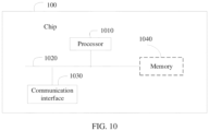
- this application provides a chip or a chip system.
- the chip or the chip system includes at least one processor and a communication interface.
- the communication interface and the at least one processor are interconnected by using a line.
- the at least one processor is configured to run a computer program or instructions, to implement the key processing method according to any one of the first aspect or the possible implementations of the first aspect.
- the communication interface in the chip may be an input/output interface, a pin, a circuit, or the like.
- the chip or the chip system described in this application further includes at least one memory, and the at least one memory stores instructions.
- the memory may be a storage unit inside the chip, for example, a register or a cache, or may be a storage unit (for example, a read-only memory or a random access memory) of the chip.
- an embodiment of this application provides a computer program product.
- the computer program product runs on one or more processors, the method according to any one of the first aspect or the possible implementations of the first aspect is implemented.
- an embodiment of this application provides an electronic device, including at least one processor, where the at least one processor is configured to perform the method according to any one of the first aspect or the possible implementations of the first aspect.
- the electronic device described in this application may further include an interface circuit.
- the interface circuit is configured to provide an information input and/or an information output for the at least one processor.
- the at least one processor is configured to perform the method according to any one of the first aspect or the possible implementations of the first aspect.
- first and second are used in embodiments of this application to distinguish between same items or similar items that provide basically same functions or purposes.
- a first memory slot and a second memory slot are merely used to distinguish between different memory slots, but not to limit a sequence thereof.
- a person skilled in the art may understand that the words such as “first” and “second” do not limit a quantity or an execution sequence, and the words such as “first” and “second” do not indicate a definite difference.
- example or “for example” is used to represent giving an example, an illustration, or a description. Any embodiment or design solution described as an “example” or “for example” in this application should not be explained as being preferred or advantageous over other embodiments or design solutions. To be precise, the word such as “example” or “for example” is intended to present a related concept in a specific manner.
- “And/or” describes an association relationship between associated objects, and represents that three relationships may exist.
- a and/or B may represent the following cases: Only A exists, both A and B exist, and only B exists, where A and B may be singular or plural.
- the character "/" generally indicates an "or” relationship between the associated objects.
- At least one of the following items (pieces) or a similar expression thereof indicates any combination of these items, including a single item (piece) or any combination of a plurality of items (pieces).
- a, b, or c may represent “a, b, c, a, and b", “a and c", “b and c” or "a, b, and c", where a, b, and c may be singular or plural.
- content such as a memory slot used for key update, key information in the key memory slot, a security verification condition of a key, and an interface supported by the SHE is defined.
- a memory slot used for key update in the SHE specifications some key memory slots used for key update and types and addresses of the memory slots are described, as shown in Table 1.
- Table 1 Schematic table of memory slots Name of key memory slot Address (address) (hexadecimal) Memory area (memory area) SECRET_KEY 0 Read-only memory MASTER_ECU_KEY 1 Non-volatile (non-volatile) memory slot BOOT_MAC_KEY 2 BOOT_KEY 3 KEY_1 4 KEY_2 5 KEY_3 6 KEY_4 7 KEY_5 8 KEY_6 9 KEY_7 a KEY_8 b KEY_9 c KEY_10 d RAM_KEY e Volatile (volatile) memory slot
- non-volatile indicates a non-volatile memory slot used to store a fixed key or a security check code BOOT_MAC used for secure boot.
- Volatile indicates a volatile memory slot.
- the "address” column lists location numbers of memory slots that can store keys in the SHE mechanism. The following describes main key memory slots in the embodiments of this application and functions of the key memory slots.
- MASTER_ECU_KEY may be used to store a master key of the current ECU, and is used only to update the master key of the current ECU or another key in the SHE.
- MASTER_ECU_KEY may be preset in a production line when each component is produced.
- BOOT_MAC_KEY and BOOT_MAC are respectively a key used for software integrity verification and a software integrity check code during SHE secure boot.
- KEY_1 to KEY_10 may be used to store a symmetric key (or referred to as a cipher key, an integrity key, or the like) for in-vehicle communication between devices.
- a symmetric key or referred to as a cipher key, an integrity key, or the like
- the in-vehicle key may be stored in these memory slots.
- KEY_1 to KEY_10 need to be verified based on MASTER_ECU_KEY or an existing key, and may be separately loaded into each component in the vehicle by using a tool from the vehicle manufacturer or the cloud.
- RAM_KEY may be used for any purpose, and may be operated by running the following three commands: CMD_LOAD_PLAIN_KEY: Stores a key in this location in plaintext. The SHE verifies an input parameter of this command. This means that any caller can store any value in this location by using this command, and therefore no security guarantee is provided.
- CMD_LOAD_KEY Stores a key in this location in ciphertext.
- the SHE verifies integrity of an input parameter and then decrypts the parameter.
- the input parameter may be understood as a parameter that is input.
- the input parameter may be used to transfer a parameter to a command such as CMD_LOAD_KEY for use.
- CMD_EXPORT_RAM_KEY Exports, in ciphertext, a key stored in this location.
- the exported parameters include M1 to M5.
- M1 to M3 can be used as input parameters of CMD_LOAD_KEY Then M1 to M3 can be stored in RAM_KEY in ciphertext by running the CMD_LOAD_KEY command (or SECRET_KEY is used for encryption and integrity protection).
- key update may be implemented based on the memory slots in Table 1.
- each key may include some additional information, for example, a related identifier such as a writing protection identifier and a secure boot failure identifier.
- the related identifiers may be shown in Table 2.
- Table 2 Schematic table of other identifiers used in key storage Write protection (writing protection) Secure boot failure (secure boot failure) Debugger activation (debugger activation) Wildcard unique identification item (wildcard UID) Key usage (key usage) Plain key (plain key) Counter (counter) Overall data (overall data [bit])
- Write-protection indicates write protection. If write-protection is set to 1, the key cannot be updated even if the key is leaked. If write-protection is 0, update is allowed.
- the wildcard unique identification item may indicate whether a wildcard UID can be used to load (or referred to as overwrite update) a key into a corresponding memory slot. If the wildcard UID is 1, the key can be loaded by using the wildcard UID. If the wildcard UID is 0, the key cannot be loaded by using the wildcard UID. According to the SHE specifications, when the value of UID is 0, the value of wildcard UID is also 0.
- the UID is a device identifier. For example, the UID may be an identification number of an ECU.
- Counter indicates an update counter of a key. Each time the key is updated, the counter value increases by 1. The counter can be used to prevent replay attacks.
- An electronic control unit can be an electronic control apparatus based on a single-chip microcomputer, has powerful mathematical operation and logic judgment, data management, and data processing functions.
- the ECU can be divided into a hardware part and a software part.
- the hardware part is a physical component of the ECU, and the software part is an instruction and data system that implements the ECU control function.
- the ECU processes a signal sent by a sensor and controls, by using a control instruction, a corresponding execution component to perform an operation according to the instruction.
- a pre-shared key also referred to as a shared key
- PSK is a key used for identity authentication during encryption. For example, before data exchange is performed between devices, a PSK may be shared, and communication is maintained between the devices, so that mutual identity authentication is performed before another identity authentication method such as "user name + password" is applied.
- a cipher-based message authentication code (cipher-based message authentication code, CMAC) can be used as a message signature.
- a memory slot may be a logical address or a physical address of the memory slot.
- the location of the first memory slot may be a memory slot 1
- the location of the second memory slot may be a memory slot 2.
- the memory slot 1 and the memory slot 2 may be different or may be the same.
- a first device may be a cloud device, an in-vehicle device, another terminal device, or the like.
- the first device may support key update based on the SHE mechanism or the HSM mechanism.
- the cloud device may be a server configured to deliver a key, or may be a proxy server.
- the proxy server may be a server serving a vehicle fleet. This is not limited in the embodiments of this application.
- the in-vehicle device may be a vehicle in any form that supports key update, or may be any component of the vehicle, such as an ECU, or a vehicle-assisted device (such as a vehicle charging pile) in any form. This is not specifically limited in this embodiment of this application.
- the cloud device may be a key client-side server configured to update a key, or may be a vehicle fleet server or any other possible server that obtains and updates a key from the client-side server.
- the terminal device may also be user equipment (user equipment, UE), a mobile station (mobile station, MS), a mobile terminal (mobile terminal, MT), or the like.
- the terminal device may be a mobile phone (mobile phone), a smart television, a wearable device, a tablet computer (Pad), a computer with a wireless transceiver function, a virtual reality (virtual reality, VR) terminal device, an augmented reality (augmented reality, AR) terminal device, a wireless terminal in industrial control (industrial control), a wireless terminal in self-driving (self-driving), a wireless terminal in remote surgery (remote medical surgery), a wireless terminal in a smart grid (smart grid), a wireless terminal in transportation safety (transportation safety), a wireless terminal in a smart city (smart city), a wireless terminal in a smart home (smart home), or the like.
- the key processing methods according to the embodiments of this application may be applied to a scenario in which various types of vehicles update keys, for example, in a scenario in which a vehicle such as an intelligent connected vehicle, a self-driving vehicle, or a new energy vehicle interacts with a cloud device to update a key.
- a vehicle such as an intelligent connected vehicle, a self-driving vehicle, or a new energy vehicle interacts with a cloud device to update a key.
- the vehicle needs to use a dedicated tool to connect to the cloud KMS of the vehicle at a specially authorized maintenance center or the factory, and then connect to in-vehicle devices one by one to load the new key, to update the key.
- the hardware security mechanism is the SHE mechanism.
- the following describes in detail loading of a key based on the SHE mechanism.
- security verification conditions of the key needs to be met.
- the security verification conditions may be shown in Table 4.
- Table 4 Schematic table of security verification conditions Non-volatile Volatile ROM Plaintext (plaintext) Slot to update MASTER_ ECU_KEY BOOT _MAC _KEY BOOT _KEY KEY_ ⁇ n> RAM_K EY SECRET_ KEY UID MASTER_ECU _KEY X BOOT_MAC_ KEY X X BOOT_KEY X X KEY_ ⁇ n> X X RAM_KEY X X X SECRET_KEY UID
- X indicates that an existing key (column) needs to be used for security verification when a key (row) is loaded.
- the existing key is used to derive a cipher key K1 and an integrity key K2 to protect input parameters of CMD_LOAD_KEY.
- KEY_ ⁇ n> indicates KEY_1 to KEY_10.
- a key such as MASTER_ECU_KEY, BOOT_MAC_KEY, BOOT_MAC or KEY_ ⁇ n>
- a key such as MASTER_ECU_KEY, BOOT_MAC_KEY, BOOT_MAC or KEY_ ⁇ n>
- the original key or MASTER_ECU_KEY stored in the location needs to be known in advance.
- the user may drive the vehicle to a specially authorized maintenance center.
- Professional maintenance personnel can update keys based on the SHE mechanism. For example, when the maintenance personnel load a new key into the MASTER_ECU_KEY location in the SHE, the maintenance personnel can use a tool to link to the cloud interface, obtain a current value of MASTER_ECU_KEY in the SHE, and build input parameters of the CMD_LOAD_KEY command based on the current value of MASTER_ECU_KEY. Further, the tool can be used to connect to each device interface in the vehicle, and then the CMD_LOAD_KEY command is run to load the new key.
- the SHE performs security verification (such as integrity check and decryption) on the input parameters in the CMD_LOAD_KEY command based on the value stored in the current MASTER_ECU_KEY location. After the verification succeeds, the new key carried in the command can be stored in the MASTER_ECU_KEY location to complete loading of the key.
- security verification such as integrity check and decryption
- key update operations can be simplified, and efficiency of key update can be improved.
- FIG. 1 is a schematic diagram of an example of a key processing scenario according to an embodiment of this application.
- the scenario may include a car 101 and a cloud device (for example, a server) 102.
- the car 101 includes a first component whose key needs to be updated.
- the first component may be an ECU.
- the user may trigger, on a screen of a head unit or a mobile phone, a corresponding button used for updating the key.
- the car 101 and the cloud device 102 may exchange data based on a hardware security mechanism by using a key processing method according to an embodiment of this application, so that the cloud device 102 transmits a new key to the first component in the car 101, to complete key update.
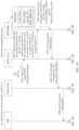
- FIG. 2 is a schematic flowchart of a key processing method according to an embodiment of this application. As shown in FIG. 2 , the method includes:
- the first memory slot is used to store a first key
- the second memory slot is used to store a second key
- the second key is an update key of the first key
- the first memory slot may be one memory slot, or may be a plurality of memory slots
- the second memory slot may be one memory slot, or may be a plurality of memory slots.
- a third memory slot may further exist.
- the first device determines the first memory slot, and the first device determines the second memory slot and the third memory slot that are associated with the first memory slot.
- the first device determines the first memory slot and the third memory slot, and the first device determines the second memory slot that is associated with the first memory slot and the third memory slot.
- This embodiment of this application imposes no limitation on a quantity, a property, or the like of the memory.
- the second memory slot may be predefined by the hardware security mechanism, or the second memory slot is determined according to a first command received by an interface in the hardware security mechanism.
- the first command may be a command generated based on setting of the second memory slot by a user.
- the predefinition may be understood as that the user does not need to set the second memory slot, and the hardware security mechanism can automatically generate the second memory slot based on a setting of the hardware security mechanism.
- the first memory slot may be understood as a master memory slot
- the second memory slot may be understood as a slave memory slot.
- the first memory slot may be a memory slot that is always used to store a key.
- the second memory slot may be a memory slot temporarily set or fixedly set for storing a key.
- the temporary setting may be that a second memory slot is temporarily set for use, and is released after being used; and the fixed setting may be that a second memory slot is set before being used, and the second memory slot is maintained after being used.
- the hardware security mechanism may temporarily set a second memory slot for the first memory slot. After the key is updated, the second memory slot may be released. In this scenario, the second memory slot may be used when an in-vehicle KMS updates the key. In another scenario and a service, the second memory slot cannot be used, and the second memory slot cannot be sensed.
- the second memory slot may be set in advance before the key is updated, and after the key is updated, the second memory slot may continue to be maintained.
- the in-vehicle KMS updates the key
- it may be determined, based on a service requirement, whether the second memory slot needs to be accessed.
- the hardware security mechanism may be an extended hardware security mechanism.
- the hardware security mechanism may be an extended SHE mechanism or an extended HSM mechanism.
- the hardware security mechanism is an extended SHE mechanism.
- the extended SHE mechanism defines content such as additional storage information during SHE key storage, and a first command supported by the SHE.
- the extended SHE mechanism may include additional storage information when the extended SHE is used to store the key based on Table 2, as shown in Table 5.
- Table 5 Additional storage information when the SHE key is stored Build status (buildstatus (1 bit)) Support update (supportupdate (1 bit)) Key usage (inuse (1 bit)) Slave memory slot (isslave (1 bit)) Memory slot pair (pairslot (8 bits)) MASTER_ECU_KEY X X X X/- X/- BOOT_MAC_KEY X/- X/- X/- X/- X/- BOOT_KEY X/- X/- X/- X/- KEY_ ⁇ n> X X X X/- X/- RAM_KEY SECRET_KEY UID
- X indicates that content in the current row may be included during storage.
- the build status buildstatus of MASTER_ECU_KEY is X, it may indicate that when MASTER_ECU_KEY is stored, content of buildstatus may be included; or when MASTER_ECU_KEY is stored, support update supportupdate, key usage inuse, memory slot slave isslave, and a memory slot pair slot pairslot in the corresponding row may include content of buildstatus.
- X/- indicates that it may be determined, according to a requirement, whether content of the item/row is included during storage, for example, may be customized according to a user service.
- Blank indicates that content of the item or row may not be included during storage.
- storage information of the first key may include:
- First indication information information used to indicate a key build status.
- a field format of the first indication information may be: build status buildstatus (1 bit). When buildstatus is 0, it indicates that no key is built in the memory slot, or it is understood that a key is invalid in a corresponding storage location; or when buildstatus is 1, it indicates that a key in the memory slot is successfully built, or it is understood that the key is valid in a corresponding storage location.
- Second indication information information used to indicate whether a key supports update.
- a field format of the second indication information may be: support update supportupdate (1 bit). When supportupdate is 1, it may indicate that the memory slot supports update; or when supportupdate is 0, it may indicate that the memory slot does not support update, and a value of pairslot can be ignored.
- Third indication information information used to indicate whether a key is being used.
- a field format of the third indication information may be: key usage inuse (1 bit). When inuse is 1, it may indicate that a key stored in the location is being used; or when inuse is 0, it may indicate that a key stored in the location is not being used. For a pair of keys, there is always one key whose "inuse" is set to 1.
- Fourth indication information information used to indicate that a key is an un-updated key or an updated key.
- a field format of the fourth indication information may be: inuse + buildstatus. If the value of inuse is 0 and the value of buildstatus is 1, the key in the memory slot is valid but cannot be used in a service. If the value of buildstatus is 0, the inuse flag can be ignored.
- inuse and buildstatus can be used together to mark the new key as "built successfully + in use", or mark the old key as "built successfully + disabled”.
- inuse, buildstatus, and counter can be used together to determine whether the key is a new key or an old key.
- a field format of the fifth indication information may be as follows: memory slot slave isslave (1 bit). When isslave is 0, it may indicate that the memory slot is a master memory slot; or when isslave is 1, it may indicate that the memory slot is a slave memory slot. A default value of isslave may be 0. It should be noted that isslave is valid only when supportupdate is set to 1. For the pairing (pair) solution, this field may be omitted. For the slave (slave) solution, this field is included.
- Sixth indication information information used to indicate a memory slot paired with the memory slot of the first key.
- a field format of the sixth indication information may be: memory slot pair slot pairslot (8 bits). It should be noted that isslave is valid only when supportupdate is set to 1. For the pairing solution, this field may be included. For the slave solution, this field may not be included.
- the following first command may be received based on an interface.
- the extended SHE mechanism in this embodiment of this application may be: Based on Table 4, an interface in the extended SHE is used to receive the first command.
- the first command may include: a command used to instruct to pair the first memory slot and the second memory slot, a command used to instruct to unpair the first memory slot and the second memory slot, a command used to instruct to update a key, a command used to instruct to clear an un-updated key, a command used to instruct to query key information in the first memory slot and/or the second memory slot, or a command used to instruct to transfer a key from one memory slot to another memory slot.
- First pairing command used to set the first memory slot and the second memory slot as a pair.
- a field format of the first pairing command may be CMD_SET_KEY_PAIRSLOT.
- First unpairing command used to unpair the first memory slot and the second memory slot.
- a field format of the first unpairing command may be CMD_RESET_KEY_PAIRSLOT.
- First command for setting a slave memory slot used to set a second memory slot for the first memory slot.
- a field format of the first command for setting a slave memory slot may be CMD_SET_KEY_SLAVESLOT.
- First command for unbinding a slave memory slot used to unbind a second memory slot from the first memory slot.
- a field format of the first command for unbinding a slave memory slot may be CMD_RESET_KEY_SEAVESEOT.
- First command for updating a key used to store a new key in a first memory slot (or a second memory slot) specified in the SHE.
- a field format of the first command for updating a key may be CMD_LOAD_KEY.
- First command for clearing a key before update used to clear the second key in the second memory slot associated with the first memory slot.
- a field format of the first command for clearing a key before update may be CMD RESET PAIR_KEYINFO.
- Second command for clearing a key before update used to overwrite the content of the second memory slot to the first memory slot specified by an input parameter, and clear the content of the second memory slot.
- a field format of the second command for clearing a key before update may alternatively be CMD_SWITCH_SLAVE_KEYINFO.
- First command for querying key information in a memory slot used to query key information (excluding the key) of the first memory slot (or the second memory slot).
- the key information may include information such as a key flag, a counter, or a pairslot. If there is pair or slave information, key information corresponding to the pairslot may also be returned.
- a field format of the first command for querying key information in a memory slot may be CMD_GET_KEY_INFO.
- First command for transferring a key from one memory slot to another memory slot used to completely transfer a key from one memory slot to another memory slot.
- a field format of the first command for transferring a key from one memory slot to another memory slot may be CMD_MOVE_KEY_SLOT.
- First command for obtaining a key from a second memory slot used to instruct to obtain a key from the second memory slot.
- a field format of the first command for obtaining a key from a second memory slot may be CMD_SET USE_SLAVE KEYINFO.
- C1VID_SET USE SLAVE_KEYINFO may also notify the SHE that the key in the specified memory slot needs to be read from the second memory slot when the key in the specified memory slot is subsequently used. If the first memory slot is not bound to the second memory slot, the command fails to be executed.
- First command for obtaining a key from a first memory slot used to instruct to obtain a key from the first memory slot.
- a field format of the first command for obtaining a key from the first memory slot may be CMD_RESET_USE_SLAVE_KEYINFO.
- CMD_RESET_USE_SLAVE_KEYINFO may also notify the SHE that the key in the specified memory slot needs to be read from the first memory slot when the key is subsequently used. Regardless of whether the first memory slot is bound to the second memory slot, the command returns success.
- S202 further includes: the first device determines, based on the hardware security mechanism, the second memory slot associated with the first memory slot.
- the hardware security mechanism is used to update the first key.
- the first memory slot may be understood as a memory slot for storing the first key
- the second memory slot may be understood as a slave memory slot of the first memory slot.
- the first device may determine, based on a method for setting a slave memory slot, for example, who specifies a slave memory slot, or whether a same or different slave memory slots are used when different keys are updated, and a combination of the foregoing manners, how to configure a slave memory slot for the first memory slot based on the hardware security mechanism.
- the setting method may be temporary setting or fixed setting. Specifying the slave memory slot may be specifying by a user or automatically specifying by the SHE hardware mechanism. Table 6 shows a combination of the foregoing factors and impact of each combination on a user and a service.
- Table 6 Setting combinations of the slave memory slot and analysis of impact on a user and a service No. Time for setting the slave memory slot Who specifies the slave memory slot? Slave memory slots of different keys Can the slave memory slot be sensed by a user? If the slave memory slot needs to be sensed in a service, can it be implemented? If the slave memory slot does not need to be sensed in a service, can it be implemented? If the slave memory slot needs to be sensed in the update service of the in-vehicle KMS to support power-off restart, can it be implemented? 1 Temporary setting User-specified Same Restricted No Yes, but the key needs to be moved (moved). The KMS is temporarily specified.
- the service may be understood as another service other than the in-vehicle KMS, for example, a service such as a secure information communication service inside or outside a vehicle.
- the slave memory slot needs to be sensed in a service, it may be understood as that the service may use the second memory slot.
- the first memory slot and the second memory slot may be alternately used to store an updated key in the service.
- the slave memory slot does not needs to be sensed in a service, it may be understood as that the first memory slot is used in the service. For example, when a key is updated, the first memory slot may be used to store an updated key in the service.
- a user may be understood as a service in which a key stored in the hardware security mechanism needs to be used.
- the user may include a service such as an in-vehicle KMS or an in-vehicle data communication service.
- a slave memory slot needs to be sensed in the update service of the in-vehicle KMS to support power-off restart: It may be understood that, when the in-vehicle KMS updates a key, some in-vehicle devices may experience an exception such as power-off restart. To ensure that a device is still managed by the vehicle after experiencing power-off restart or the like, the in-vehicle KMS needs to continue a process of accessing a key temporarily stored in the second memory slot when updating the key.
- Moving is required: If existence of a slave memory slot does not need to be sensed in a service, and it is expected to always use a key in a same memory slot for secure communication before and after key update, the hardware security mechanism needs to support moving a key from one memory slot (for example, the second memory slot) to another memory slot (for example, the first memory slot) after key update. Moving may be an independent function provided and operated by a user, or may be operated by a system based on the hardware security mechanism.
- Fixed setting For the hardware security mechanism, there are three manners for implementing fixed setting.
- the fixed setting may be limited by using hardware logic during production of a security chip.
- the fixed setting may be limited by using firmware logic in the hardware security mechanism, and the fixed setting may be upgraded with a software package.
- the fixed setting may be set by a user.
- a user specifies a slave memory slot: It may be understood that the hardware security mechanism needs to provide a corresponding user interface to support setting of the slave memory slot.
- a hardware mechanism specifies a slave memory slot:
- the slave security area can be set in two manners.
- a user interface may be provided.
- a specific location of the slave memory slot may be automatically specified by the hardware mechanism. In this manner, corresponding temporary setting may be performed, or corresponding fixed setting may be performed.
- a user interface may not be provided.
- Slave memory slot for different keys If the same slave memory slot is used, occupancy of the memory slot can be reduced. If different slave memory slots are used, key backup can be supported while key update is supported, so that key reliability is improved, and concurrent update of a plurality of different keys is supported.
- methods for setting a slave memory slot may be divided based on whether it can be implemented when a slave memory slot needs to be sensed in a service.
- the methods may be divided into two types: a solution in which it can be implemented when the slave memory slot needs to be implemented in a service is referred to as a pairing solution, and it may be understood that in the pairing solution, the slave memory slot may be used in the service; and a solution in which it cannot be implemented when the slave memory slot needs to be sensed in a service is referred to as a slave solution, and it may be understood that in the slave solution, the master memory slot is used in the service.
- a pairing solution a solution in which it cannot be implemented when the slave memory slot needs to be sensed in a service
- slave solution a solution in which it cannot be implemented when the slave memory slot needs to be sensed in a service
- the master memory slot is used in the service.
- setting of the slave memory slot and a key update process are described by using the pairing solution and the slave solution as examples.
- the first device may be an in-vehicle device, or may be a cloud device.
- the second device is a cloud device; or when the first device is a cloud device, the second device is an in-vehicle device.
- An implementation corresponding to a scenario in which the first device is an in-vehicle device and an implementation corresponding to a scenario in which the first device is a cloud-end device are different.
- a key processing method may include the following content.
- a method for setting, by the first device, the slave memory slot for storing a first key includes: the first device receives a first message from a second device; the first device verifies first encryption information; and the first device configures a second memory slot for the first memory slot if the first encryption information is successfully verified.
- the second memory slot may be understood as a slave memory slot; and the first encryption information is generated by the second device based on a hardware security mechanism.
- the first message includes the first encryption information used to indicate a first memory slot and a second memory slot; and the first encryption information includes a first parameter M1 and a second parameter M2, where M1 is related to information in the first memory slot and information in the second memory slot, and M2 is related to M1 and the first key.
- the pairing solution may be further divided into two manners based on a quantity of memory slots provided by the cloud device to support key update, including manner 1 and manner 2. For example, in manner 1, the cloud device sets one memory slot to support key update (as shown in the embodiment corresponding to FIG. 3A and FIG. 3B ); and in manner 2, the cloud device sets two memory slots to support key update (as shown in the embodiment corresponding to FIG. 4A and FIG. 4B ).
- Combinations corresponding to the pairing solution are shown in Table 8.
- Table 8 Combinations corresponding to the pairing solution No. Time for setting the slave memory slot Who specifies the slave memory slot? Slave memory slots of different keys Can the slave memory slot be sensed by a user? If the slave memory slot needs to be sensed in a service, can it be implemented?
- Solution 6 Fixed setting User-specified Different Yes Yes Pairing solution 8 Hardware mechanism Different Yes Yes Pairing solution
- a memory slot is automatically specified.
- the slave memory slot does not need to be specified for each interface in the SHE user function extension summary.
- the hardware security mechanism supports automatic setting of the memory slot, the user can enable a key to use the slave memory slot, or the user can disable a key from using the slave memory slot. Based on the following solution, a corresponding parameter may be properly modified, and details are not described herein again.
- the fixed setting mode is defined by using the hardware logic in the hardware security mechanism, or the fixed setting mode is defined by using firmware logic in the hardware security mechanism, but the fixed setting can be upgraded with a software package, an interface for a user setting function does not need to be provided, but an interface for using a key in a slave memory slot needs to be provided.
- the slave memory slot may be specified by hardware logic or fixed logic, and the slave memory slot is used based on an interface during key update.
- a method for setting a slave memory slot for a first memory slot is described by using an example in which a slave memory slot (for example, No. 6 in Table 8) is specified by a user based on fixed setting in the pairing solution.
- a slave memory slot for example, No. 6 in Table 8
- two memory slots are configured as a pair. It may be understood that the pairing solution below may be based on a manner in which a slave memory slot is specified by a user, and details are not described below.
- a memory slot is paired with MASTER_ECU_KEY by using a CMD_SET_KEY_PAIRSLOT command before key update.
- the memory slot at the memory slot 9 is paired with MASTER_ECU_KEY, as shown in Table 9.
- Table 9 Schematic table of setting a memory slot 1 and the memory slot 9 as a pair and supporting update of MASTER_ECU_KEY Content (content) memory slot pairslot Description
- MASTER_ECU_KEY 1 9 KEY_6 is paired with the memory slot 1, and is used to support update of the key of MASTER_ECU_KEY.
- the memory slot 9 is paired with MASTER_ECU_KEY, and is used to support update of the key of MASTER _ ECU_KEY KEY_7 10 KEY_8 11 KEY_9 12 KEY_10 13
- the memory slot KEY_6 corresponding to the location of the memory slot 9 may be understood as a second memory slot.
- the slave memory slot is referred to as the second memory slot below.
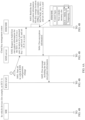
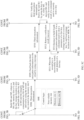
- FIG. 3A and FIG. 3B are a schematic flowchart of setting a second memory slot according to an embodiment of this application.
- the procedure may include a target device (for example, an ECU 1) in a vehicle and a cloud key management center.
- the in-vehicle devices may include:
- the in-vehicle KMS-server may be responsible for exchanging messages with the KMS-server in the cloud key management center.
- the device is used to assist in managing functions such as pair configuration and key update on the device and other in-vehicle devices.
- the forwarding and management device may include an ECU on a controller area network (controller area network, CAN) or CAN flexible data-rate (flexible data-rate, FD) bus; and the ECU needs to be managed by using a device such as a gateway, a vehicle running dynamic control system (vehicle running dynamic control system, VDC), a multi-domain controller (multi-domain controller, MDC), or a continuous damping control (continuous damping control, CDC) system.
- VDC vehicle running dynamic control system
- MDC multi-domain controller
- CDC continuous damping control
- In-vehicle KMS-client manages another device than the KMS-agent and the KMS-server.
- the cloud key management center may include:
- the first device is an in-vehicle device
- the second device is a cloud device.
- a procedure based on manner 1 may include the following steps.
- S301 A user starts a KMS configuration change of the first device.
- the KMS configuration change may be a configuration change triggered based on a second memory slot set by a user. For example, when the user needs to update an in-vehicle key, the user may pair two memory slots on a screen of a head unit or a mobile phone. In response to a setting operation of the user, an in-vehicle KMS configuration change may be started in the cloud key management center.
- S302 The KMS-server in the second device requests to build first encryption information for an ECU 1.
- the first encryption information may include the following parameters: (1,9) are paired; location of a protected key: 1; and local storage location of a key: X.
- the KMS-server in the second device sends the foregoing data to the HSM/SHE in the second device.
- the first encryption information may be built by using the first pairing command CMD_SET_KEY_PAIRSLOT that is used for pairing the first memory slot and the second memory slot.
- the KMS-server of the second device may request to build an input parameter of the CMD_SET_KEY_PAIRSLOT command for the target device.
- CMD_SET_KEY_PAIRSLOT For example, function descriptions of CMD_SET_KEY_PAIRSLOT may be shown in Table 10.
- Table 10 Schematic table of the function descriptions of CMD_SET_KEY_PAIRSLOT Parameter (parameter) Direction (direction) Width (width)/Bits (bits) M1 in/Input parameter 24 M2 in/Input parameter 128
- CMD_SET_KEY_PAIRSLOT indicates that two memory slots are bound as a pair to support key update.
- first parameter M1 key storage location (KEY_ID)
- counter; second parameter M2 CMAC (key, M1).
- ” may be understood as concatenation.
- M1 may be a concatenation of bytes corresponding to KEY_ID, memory slot 1, memory slot 2, and counter.
- bytes such as KEY_ID, memory slot 1, memory slot 2, and counter may be sequentially transmitted.
- KEY_ID indicates a memory slot of a key (key) to be used as a key used for computing M2, for example, KEY_ID may be MASTER_ECU_KEY of the target device.
- key indicates a key corresponding to KEY_ID.
- counter The counter value may be a larger value of the counter value in memory slot 1 and memory slot 2 plus 1 to prevent replay attacks.
- CMD_SET_KEY PAIRSLOT instructs the SHE to set memory slot 1 and memory slot 2 as the key pair of each other. It may be understood that the value of "memory slot 1" is set to the pairslot location of the key in the "memory slot 2", and the value of "memory slot 2" is set to the pairslot location of the key in the "memory slot 1".
- the SHE can automatically set the supportupdate value of the key to 1.
- ERC_KEY_INVALID may be returned.
- a storage location of a key in the second device may be different from a storage location of a key of each device in the first device.
- the hardware security mechanisms may be different. Therefore, when the second device builds an input parameter of the CMD_SET_KEY PAIRSLOT command, an address memory slot (or another representation manner of a storage address) of a key (key) (which may refer to MASTER_ECU_KEY in this embodiment of this application) used for computing M2 in the second device may be different from a storage location of each device in the first device. Therefore, when building an input parameter of the CMD_SET_KEY_PAIRSLOT command, the HSM or the SHE in the second device needs to provide enough parameter information such as storage locations of the MASTER_ECU_KEY in the target device and the second device.
- That the KMS-server in the second device sets (1, 9) as a pair may indicate that the memory slot 1 and the memory slot 9 in the target device are paired.
- 9", “1 and 9”, and “1,9” may be understood as that the memory slot 1 and the memory slot 9 in the target device are paired.
- the hardware security mechanism of the second device and the hardware security mechanism of the target device need to support generation of the input parameter of the CMD_SET_KEY PAIRSLOT command by using a value in a corresponding manner.
- the location of the memory slot herein corresponds to the physical address of the memory slot.
- Location of a protected key 1, which may indicate that a storage location of a key used for computing M2 in the target device is the memory slot 1.
- X which may indicate that a storage location of a key used for computing M2 in a secure environment of the second device (or understood as a cloud) is X.
- the key may be stored in X in the second device, and when an input parameter is built, the key may be obtained from X.
- a storage location in the second device is generally different from a storage location in the target device.
- S303 The HSM/SHE in the second device builds first encryption information.
- counter; M2 CMAC (key, M1).
- KEY_ID refers to a storage location of a key in the target device, or a storage location of a key in the cloud key management center. For example, when KEY_ID is 1, it may indicate that the storage location of the protected key in the target device is the memory slot 1.
- the KEY_ID may be selected according to a key update policy. For example, refer to the data in Table 3 provided in this embodiment of this application.
- M1 may further include another parameter, for example, a UID.
- M1 UID
- the key of the target device from the local storage location X of the second device may be obtained when the MAC in M2 is computed by using the CMAC algorithm.
- the key needs to be the same as the key corresponding to KEY_ID in the target device.
- a method for building the input parameters of the CMD_SET_KEY_PAIRSLOT command by the HSM/SHE in the second device may be as follows:
- the method for building the input parameters of the CMD_SET_KEY PAIRSLOT command by the HSM/SHE in the second device may be: an authorized dedicated tool is used to connect to the second device to obtain a key of a corresponding vehicle, and then the input parameters are built.
- the method for building the input parameters of the CMD_SET_KEY_PAIRSLOT command by the HSM/SHE in the second device may alternatively be: a KMS (for example, the KMS-server, the KMS-agent, or the KMS-client) of each device in the first device is used to build the input parameters.
- a KMS for example, the KMS-server, the KMS-agent, or the KMS-client
- the KMS of each device in the first device builds identity authentication information by using the second device, and sends the identity authentication information to the KMS of each device in the first device.
- the identity authentication information is used by the KMS of each device in the first device to perform identity authentication with the SHE or HSM of the current device.
- the KMS of each device obtains the SHE of the device or the SHE of another device, and sets a temporarily authorized key required by the pair.
- the HSM/SHE in the second device sends the first encryption information to a KMS-server in the second device.
- the KMS-server in the second device receives the first encryption information sent by the HSM/SHE in the second device.
- the KMS-server in the second device sends the first message including the first encryption information to each device (for example, the KMS-S/A/C) in the first device.
- the KMS-S/A/C in the first device receives the first encryption information sent by the KMS-server in the second device.
- the first message may include the first encryption information, and the first encryption information may be input parameters (M1, M2) of the CMD_SET_KEY_PAIRSLOT command.
- the KMS-S/A/C in the first device sends the first encryption information to the SHE in the first device.
- the SHE in the first device receives the first encryption information sent by the KMS-S/A/C in the first device.
- S307 The SHE in the first device verifies the first encryption information.
- the SHE in the first device may use a key in a key storage location in M1 to compute a MAC value in M1, and compare the MAC value in M1 with that in M2 to verify integrity; and verify validity of the counter of the key. After the verification succeeds, the SHE in the first device pairs the memory slot 1 and the memory slot 9.
- the SHE (or the HSM or the like) in the first device may compute the MAC value in M1 by using a key (which may be MASTER_ECU_KEY in this embodiment of this application) corresponding to KEY_ID in M1, and compare the MAC value with that in M2. If the MAC in M1 is equal to that in M2, integrity verification succeeds, and subsequent verification is continued; or if the MAC in M1 is not equal to that in M2, the integrity verification fails, the current operation is prohibited, and a failure is returned.
- a key which may be MASTER_ECU_KEY in this embodiment of this application
- the SHE in the first device verifies validity of the counter. For details, refer to a process in which the counter is verified when M1 is built. Details are not described herein again.
- the SHE in the first device checks whether the memory slot 1 and the memory slot 9 in M1 can be paired:
- the current command operation may be prohibited, and a failure is returned, which indicates that the second memory slot is occupied.
- the current command operation may be prohibited, and a failure is returned, which indicates that the second memory slot is occupied.
- the current command operation may be allowed.
- KEY_ID should be set to another key.
- the SHE in the first device may set the pairslot in the memory slot 1 to 9, and set the pairslot in the memory slot 9 to 1.
- "supportupdate" in the two memory slots (for example, 1 and 9) is set to 1, indicating that the keys in the two memory slots can be updated.
- the SHE in the first device may set the memory slot 1 and the memory slot 9 as a pair.
- the SHE in the first device sends a setting result feedback (success) to the KMS-S/A/C in the first device.
- the KMS-S/A/C in the first device receives the result feedback (success) sent by the SHE in the first device.
- the KMS-server in the second device receives the execution result (success) of CMD_SET_KEY_PAIRSLOT that is sent by the KMS-S/A/C in the first device.
- the KMS-server in the second device updates a cloud vehicle database.
- the first device updates a configuration result of the configuration file information of the corresponding KMS.
- the vehicle side or the cloud may extend the hardware security mechanism, so that the hardware security mechanism can support setting of the second memory slot for the first memory slot.
- the cloud device provides a memory slot for the key, so that a computation workload required for setting the second memory slot can be reduced, and a storage space can be optimized.
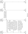
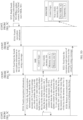
- Method 2 The cloud device sets two memory slots to support key update.
- FIG. 4A and FIG. 4B are another schematic flowchart of setting a second memory slot according to an embodiment of this application.
- the HSM/SHE in the second device may also synchronously set a pair for a key corresponding to the HSM/SHE in the second device, so that in key update logic, the HSM/SHE may temporarily store the second key in Y, and move the second key to X after the update is completed.
- a process based on manner 2 may include the following steps:
- the first encryption information may include: setting (1,9) as a pair; location of a protected key: 1; local storage location: X; and setting (X, Y) as a pair.
- the KMS-server in the second device sends the foregoing data to the HSM/SHE in the second device.
- counter, and M2 CMAC (key, M1); and pairing X and Y in the second device.
- the HSM/SHE in the second device may also refer to a historically set pair of memory slots.
- the cloud may use a memory slot that is previously used to pair with X as the memory slot for pairing with X this time.
- an internal hardware mechanism such as the HSM/SHE may automatically set a pair of memory slots for X.
- a memory slot used for pairing with X is automatically set for X.
- S404 to S410 are similar to steps S304 to S310, and details are not described herein again.
- the vehicle side or the cloud may extend the hardware security mechanism, so that the hardware security mechanism can support setting of the second memory slot for the first memory slot.
- the cloud device provides two memory slots for the key, to facilitate update and storage of the cloud key.
- the foregoing has described the process of setting the second memory slot based on the pairing solution.
- the setting of the slave memory slot may be canceled based on the pairing solution.
- the following uses the pairing solution an example to describe how to unbind the slave memory slot.
- the method further includes: the first device unbinds the second memory slot based on the hardware security mechanism.
- the second memory slot may be unbound based on the CMD_RESET_KEY_PAIRSLOT command in the SHE mechanism.
- function descriptions of CMD_RESET_KEY_PAIRSLOT may be shown in Table 11.
- Table 11 Schematic table of the function descriptions of CMD_RESET_KEY_PAIRSLOT Parameter Direction Width (bits) M1 in 16 M2 in 128
- CMD_RESET_KEY_PAIRSLOT may instruct the SHE to unpair two specified memory slots.
- the pairslot values of the two memory slots may be set to 0, and the SHE automatically sets the value of supportupdate of the key to 0, and sets the value of slave to 0.
- M1 KEY_ID
- M2 CMAC (key, M1).
- KEY_ID indicates a key (key) to be used as a key used for computing M2, for example, the KEY_ID may be MASTER_ECU_KEY of the target device.
- key indicates a key corresponding to KEY_ID.
- counter The value can be the counter value of the updated key in the memory slot plus 1 to prevent replay attacks.
- the vehicle side or the cloud may extend the hardware security mechanism, so that the hardware security mechanism can support setting of the second memory slot for the first memory slot.
- the unpairing function can simplify key update operations.
- the foregoing has described the process of setting a memory slot and unbinding a memory slot based on a pairing solution.
- the following uses the pairing solution as an example to describe a key update process.
- the method further includes: the first device updates the first key based on the hardware security mechanism.
- a process in which the first device updates the first key based on the hardware security mechanism may be as follows: The first device receives a second message from the second device; the first device obtains a second key according to the second encryption information; the first device stores the second key in the second memory slot; the first device builds third encryption information based on the second key and the second memory slot; and the first device sends the third encryption information to the second device.
- the second message includes second encryption information used to indicate the first memory slot, the second memory slot, and the second key, and the third encryption information indicates the first device to complete storage of the second key.
- the second encryption information includes a third parameter M3, a fourth parameter M4, and a fifth parameter M5, where M3 is related to information in the first memory slot and information in the second memory slot.
- M4 is related to the second key.
- M5 is related to M3, M4, and the first key.
- the second encryption information may be CMD_LOAD_KEY (M1, M2, M3).
- the third encryption information includes a sixth parameter M6 and a seventh parameter M7, where M6 is related to information in the second memory slot, and M7 is related to the second key.
- M6 is related to information in the second memory slot
- M7 is related to the second key.
- the third encryption information may be CMD_LOAD_KEY (M4, M5).
- the pairing solution may be further divided into two manners based on a quantity of memory slots provided by the cloud device to support key update, including manner A and manner B. Specifically, in manner A, the cloud device supports key update based on one memory slot; and in manner B, the cloud device supports key update based on two memory slots (as shown in the embodiment corresponding to FIG. 5A to FIG. 5D ).
- FIG. 5A to FIG. 5D are a schematic flowchart of updating a key according to an embodiment of this application.
- the procedure may include a target device (for example, an ECU 1) in a vehicle and a cloud key management center.
- Each in-vehicle device may include:
- the cloud key management center may include:
- MASTER_ECU_KEY of a target device (or referred to as an ECU 1) needs to be updated, a currently used key is stored in the memory slot 1, and memory slots 1 and 9 are paired in advance. Therefore, a detailed processing procedure of updating the MASTER_ECU_KEY key may include the following steps.
- the user may start key update, or the key update is automatically started after the first device configures the second memory slot for the first memory slot.
- S502 The KMS-server in the second device instructs to build second encryption information.
- parameters used to build the second encryption information may include: target storage location: 9; location of a protected key: 1; location storage location of old (old) MEK: X; and local storage location of new (new) MEK: Y
- the KMS-server sends the foregoing data to the HSM/SHE in the second device.
- S503 The HSM/SHE in the second device builds the second encryption information.
- a process of building the second encryption information may include: the HSM/SHE in the second device generates the new MEK for the ECU 1, and stores the new MEK into Y; obtains the current MEK of the ECU 1 from X, and derives K1 and K2; and builds input parameters (M1, M2, M3) of CMD_LOAD_KEY
- M1 UID
- new MEK); M3 CMAC (K2, M1
- CMD_LOAD_KEY For example, function descriptions of CMD_LOAD_KEY may be shown in Table 12.
- Table 12 Schematic table of the function descriptions of CMD_LOAD_KEY Parameter Direction Width (bits) M1 in/Input parameter 128 M2 in/Input parameter 256 M3 in/Input parameter 128 M4 out/Output parameter 256 M5 out /Output parameter 128
- CMD_LOAD_KEY can be used to securely store the key to a memory slot specified by the memory slot in the SHE.
- An output parameter may be understood as a parameter that is output.
- the output parameter may be used to transfer an input parameter to a command.
- UID may be a UID corresponding to the ECU, or may be a wildcard UID.
- memory slot specifies the memory slot in which the key is stored by the command.
- KKEY_ID specifies the key used to derive K1 and K2.
- ENCCBC, K1, IV 0: indicates that the Advanced Encryption Standard (advanced encryption standard, AES) cipher block chaining (cipher block chaining, CBC) mode is used for encryption.
- a value of IV may be 0, and K1 is used as a cipher key.
- KeyMemory slot indicates the second key to be stored in the memory slot.
- K3 a cipher key derived from the second key (that is, Key Memory slot) stored in the memory slot.
- counter The value is the same as the counter value in the input parameter. The value is 28 bits.
- 0...0 99 indicates that 99 bits are padded with 0s. For example, if AES_CBC_128 is used for encryption, a block length is 128 bits.
- K3 and K4 are respectively a cipher key and an integrity computation key that are derived from the second key (that is, the KeyMemory slot) stored in the memory slot.
- the HSM/SHE in the second device needs to provide sufficient parameter information for a case in which storage locations of the target device and the cloud key may be different.
- the input parameters of the CMD_LOAD_KEY command are built:
- Target storage location 9, which indicates the second key of MASTER_ECU_KEY is to be stored in the memory slot 9 in the SHE of the ECU 1.
- a protected key 1, which indicates the storage location of the key used for computing M2 and M3 in the SHE of the ECU 1 is the memory slot 1, that is, the key is MASTER_ECU_KEY This is also a storage location of the first key (which may be understood as a currently used key) during current key update in the SHE of the ECU 1.
- the cipher key K1 and the integrity key K2 are derived from the current key of MASTER_ECU_KEY
- MEK refers to MASTER_ECU_KEY
- X indicates a storage location of the first key in the HSM/SHE in the cloud security environment.
- X is used to notify the cloud security environment that the cipher key K1 and the integrity computation key K2 that are used for computing M2 and M3 need to be derived by using a key stored in X in the HSM/SHE in the cloud security environment.
- the key stored in X needs to be the same as that stored in the memory slot 1 of the ECU 1.
- MEK refers to MASTER_ECU_KEY, which indicates a temporary storage location of the new key of MASTER_ECU_KEY in the HSM/SHE in the cloud security environment when the key is updated (after the update is completed, the cloud may store the second key in X to facilitate key management in the cloud; certainly, the second key may be stored in Y all the time, and in this case, cloud management is more complex).
- a manner in which the cloud generates the second key for the ECU 1 may be as follows:
- the cloud may generate a random number rand as the second key new MEK by using a random number function provided in the HSM/SHE, and store the random number rand in Y
- the second key may alternatively be obtained by the KMS-server in the second device from another place (for example, generated by a third-party device), and sent to the HSM/SHE or the like together with a request for building an input parameter of the CMD_LOAD_KEY command.
- an input parameter of the second encryption information may be built based on a function of the CMD_LOAD_KEY and a parameter such as the second key.
- the UID may be a UID of the ECU 1. If MASTER_ECU_KEYs of all devices in the first device are the same, the UID herein may also be a wildcard UID.
- New MEK); M3 CMAC (K2, M1
- the cipher key K1 and the integrity computation key K2 are derived from the current key of MASTER_ECU_KEY
- the HSM/SHE in the second device sends the second encryption information to the KMS-server in the second device.
- the KMS-server in the second device receives the second encryption information sent by the HSM/SHE in the second device.
- the KMS-server in the second device sends the second message including the second encryption information to each device (for example, a KMS-S/A/C) in the first device.
- the second message includes second encryption information used to indicate the first memory slot, the second memory slot, and the second key.
- the KMS-S/A/C in the first device receives the second encryption information sent by the KMS-server in the second device.
- the KMS-S/A/C in the first device sends the second encryption information to the SHE in the first device, and performs key update.
- the SHE in the first device receives the second encryption information sent by the KMS-S/A/C in the first device.
- the SHE in the first device verifies the second encryption information, and may build third encryption information after the second encryption information is successfully verified.
- the second key may be set to be stored in the memory slot 9.
- a process in which the SHE in the first device verifies the second encryption information may be as follows:
- the SHE in the first device checks whether the memory slot 1 and the memory slot 9 that are indicated in M1 are paired.
- the SHE in the first device determines whether a value in the pairslot of the memory slot 1 is the memory slot 9 and whether a value in the pairslot of the memory slot 9 is the memory slot 1, or determines whether a value in the pairslot of the memory slot 1 is the memory slot 9 and whether a value in the pairslot of the memory slot 9 is the memory slot 1 and whether "supportupdate" in the memory slot 1 and the memory slot 9 is 1, to determine whether the memory slot 1 and the memory slot 9 are paired.
- the SHE in the first device may check whether the key in 1 is valid.
- the SHE in the first device checks validity of the key based on the buildstatus flag of the key. For example, when the value of buildstatus is 0, the current command operation may be prohibited; or when the value of buildstatus is 1, it may indicate that the key in 1 is valid, and the following processing may be continued.
- K1 is derived by using the key in the memory slot 1, and M2 is decrypted, to obtain values of the counter, the flags, and the new MKE.
- the SHE in the first device may compare whether the obtained counter value is greater than the counter value in the memory slot 1. If the obtained counter value is not greater than the counter value in the memory slot 1, the SHE may prohibit this operation; or if the obtained counter value is greater than the counter value in the memory slot 1, the SHE may continue to perform the following processing.
- the SHE in the first device may store the counter, the flags, and the new MKE in the memory slot 9, set the buildstatus value of "memory slot 9" to 1, and set inuse to 0.
- the SHE in the first device builds the third encryption information.
- the third encryption information indicates the first device to complete storage of the second key.
- the third encryption information includes a sixth parameter M6 and a seventh parameter M7, where the sixth parameter M6 may be understood as M4 described below, and the seventh parameter M7 may be understood as M5 described below. Details are not described below again.
- a process of building the third encryption information may include: building output parameters M4 and M5 of CMD_LOAD_KEY.
- M4 UID
- M5 CMAC (K4, M4).
- K3 a cipher key derived from the second key (that is, the new MKE) stored in the memory slot 9.
- counter The value is the same as the counter value in the input parameter. The value is 28 bits.
- 0...0 99 indicates that 99 bits are padded with 0s. For example, if AES_CBC_128 is used for encryption, a block length is 128 bits.
- K3 and K4 are respectively a cipher key and an integrity computation key that are derived from the second key (that is, the new MKE) stored in the memory slot 9.
- the SHE in the first device sends the third encryption information to the KMS-S/A/C in the first device.
- the KMS-S/A/C in the first device receives the third encryption information sent by the SHE in the first device.
- the KMS-S/A/C in the first device feeds back the third encryption information to the second device (for example, the KMS-server) by using a message.
- the KMS-server in the second device receives the third encryption information sent by the KMS-S/A/C in the first device.
- the KMS-server in the second device sends the third encryption information to the HSM/SHE in the second device.
- the HSM/SHE in the second device receives the third encryption information of the ECU 1 that is sent by the KMS-server in the second device.
- the local key is stored in Y of the second device.
- S511 The HSM/SHE in the second device verifies the third encryption information.
- a process in which the HSM/SHE in the second device verifies the third encryption information may include: the HSM/SHE in the second device derives K3 and K4 by using the key in Y, verifies M5, decrypts M4, and then verifies the third encryption information.
- a process of verifying the third encryption information is similar to the foregoing process of verifying the first encryption information and the second encryption information, and details are not described herein again.
- the HSM/SHE in the second device determines that the second key in the first device is successfully installed.
- the KMS-server in the second device receives the verification result (success) sent by the HSM/SHE of the second device.
- the first device may delete the first key based on the pairing solution.
- the following uses the pairing solution as an example to describe a process in which the first device deletes the first key.
- the procedure further includes: the first device receives fourth encryption information from the second device, where the fourth encryption information indicates the first device to delete the first key; the first device verifies the fourth encryption information; and when the fourth encryption information is successfully verified, the first device deletes the first key; or when the fourth encryption information is successfully verified, the first device deletes the first key, transfers the second key from the second memory slot to the first memory slot, and cancels the association relationship between the second memory slot and the first memory slot.
- the fourth encryption information includes an eighth parameter M8 and a ninth parameter M9, where M8 is related to information in the second memory slot, and M9 is related to M8 and the second key.
- the fourth encryption information may include CMD_RESET_PAIR_KEYINFO (M1, M2).
- S513 The KMS-server in the second device determines that the second key is successfully stored, and starts deletion of the first key.
- S514 The KMS-server in the second device instructs the HSM/SHE in the second device to build fourth encryption information.
- the fourth encryption information is used to indicate the first device to delete the first key.
- the fourth encryption information includes an eighth parameter M8 and a ninth parameter M9, where the eighth parameter M8 may be understood as M1 described below, and the ninth parameter M9 may be understood as M2 described below. Details are not described below again.
- Parameters used to build the fourth encryption information may include: when CMD_RESET_PAIR_KEYINFO is built, a storage location of a second key is 9, and a temporary local storage location of the new MEK is Y
- S515 The HSM/SHE in the second device builds the fourth encryption information.
- counter; M2 CMAC (new MEK, M1).
- CMD_RESET_PAIR_KEYINFO For example, function descriptions of CMD_RESET_PAIR_KEYINFO may be shown in Table 13.
- Table 13 Schematic table of the function descriptions of CMD_RESET_PAIR_KEYINFO Parameter Direction Width (bits) M1 in 16 M2 in 128
- CMD_RESET_PAIR_KEYINFO indicates that the SHE is instructed to clear the key information in the key pair in the memory slot, but the pairing relationship is not canceled. For example, if the memory slot includes a key pair and the value of pairslot is "memory slot 1", the key information in the memory slot 1 is cleared, the value of buildstatus is set to 0-Not built, the value of inuse is set to 0, and the value of Key ID is set to 0. In addition, the inuse flag in the memory slot is set to 1, indicating that the memory slot can be enabled immediately.
- M1 KEY_ID
- M2 CMAC (key, M1).
- memory slot clears the key information in the memory slot corresponding to the pairslot in the storage block.
- KEY_ID indicates a key (key) to be used as a key used for computing M2, for example, the KEY_ID may be MASTER_ECU_KEY of the target device.
- key indicates a key corresponding to KEY_ID.
- counter indicates the counter value in the memory slot that is used to prevent replay attacks.
- the inuse flag in the memory slot may be set to 1, indicating that the memory slot can be enabled.
- M1 9
- counter, which indicates that the first key stored in the pair (1) in the memory slot 9 needs to be cleared. If M1 9
- S516 The HSM/SHE in the second device sends the fourth encryption information to the KMS-server in the second device.
- the KMS-server in the second device may receive the fourth encryption information sent by the HSM/SHE in the second device.
- the KMS-server in the second device sends the fourth encryption information to each device (for example, a KMS-S/A/C) in the first device by using a message.
- the KMS-S/A/C in the first device receives the fourth encryption information sent by the KMS-server in the second device.
- the KMS-S/A/C in the first device sends the fourth encryption information to the SHE in the first device.
- the SHE in the first device receives the fourth encryption information sent by the KMS-S/A/C in the first device.
- S519 The SHE in the first device verifies the fourth encryption information.
- the SHE in the first device may delete the first key.
- a process in which the SHE in the first device performs verification based on the fourth encryption information may include:
- the SHE in the first device checks whether the memory slot 9 and another memory slot are paired. If the memory slot 9 and the another memory slot are not paired, the current operation may be prohibited; or if the memory slot 9 and the another memory slot are paired, the following processing may be continued.
- the SHE in the first device checks whether the key in the memory slot 9 is valid.
- the SHE in the first device may determine validity of the key based on whether the buildstatus flag of the key is 1. For example, when the value of buildstatus is 0, the current operation may be prohibited; or when the value of buildstatus is 1, it may indicate that the key in the memory slot 9 is valid, and the following processing may be continued.
- the SHE in the first device checks whether the key in the memory slot 9 is newer than that in the memory slot 1 (counter_9>counter_1). If counter_9 is greater than counter_1, the key in the memory slot 1 is cleared; the value of inuse in the memory slot 9 is set to 1, indicating that the key is enabled; and a success message is returned to the cloud key management center by using a message. If counter_9 is less than or equal to counter_1, the current command operation may be prohibited.
- the SHE in the first device clears the key in the memory slot 1, enables the key in the memory slot 9, and may set inuse of the key in the memory slot 9 to 1.
- S520 The SHE in the first device sends an execution result (success) of deleting the first key to the KMS-S/A/C in the first device.
- the KMS-S/A/C in the first device receives the execution result (success) of deleting the first key sent by the SHE in the first device.
- the KMS-S/A/C in the first device feeds back the execution result (success) of deleting the first key to the cloud (for example, the KMS-server) by using a message.
- the KMS-server in the second device receives the execution result (success) of deleting the first key sent by the KMS-S/A/C in the first device.
- the cloud may instruct the HSM/SHE in the second device to move the second key of the ECU 1 that is stored in Y to X.
- the memory slot in Y is cleared for updating other keys or other purposes. It may be understood that this manner may be a slave solution for the HSM/SHE in the second device.
- the HSM/SHE in the second device may also use the pairing solution.
- the second key is stored in Y.
- the KMS-server in the second device also needs to update the storage location of the second key of the vehicle.
- the first key may also be deleted by using the following method.
- a key deletion function command may be separately provided.
- input parameters of a command such as CMD_LOAD_KEY may also be built by another device.
- a transfer tool or a KMS-server in the second device is used to transfer the input parameters of the command to each device in the first device.
- the second key that is, new MEK
- the second key may be moved from the memory slot 9 to the memory slot 1 by adding another function command CMD_MOVE_KEY. It may be understood that this solution is equivalent to the slave manner, and a difference lies in that no isslave flag is set.
- a same common second memory slot may be used in serial for key update in different memory slots.
- a memory slot at the memory slot 9 is set as a second memory slot for the memory slot 1.
- the memory slot 1 and the memory slot 9 may be unpaired, and a memory slot at the location of the memory slot 9 may be subsequently used as a second memory slot for another memory slot.
- the first key and the second key may coexist for a long time (which may be understood as that a pair of memory slots are fixedly set for a purpose).
- a pair of memory slots are fixedly set for a purpose.
- another key may be used. This is valuable in specific service scenarios with high security requirements.
- the solution may be as follows:
- the MASTER_ECU_KEY, the memory slot 1, and the memory slot 9 are used as an example.
- Key update may be started when validity of the key stored in the memory slot 1 reaches half of a lifetime (lifetime).
- CMD_LOAD_KEY the first key is temporarily not deleted.
- the first key stored in the memory slot 1 may be preferentially used in an in-vehicle service (it may be understood that inuse in the memory slot 1 is 1, and inuse in the memory slot 9 is 0, but buildstatus of the memory slot 1 and buildstatus of the memory slot 9 are 1, indicating that both keys are valid).
- the key in the memory slot 9 can also be used.
- the key in memory slot 1 fails to be read, the key in memory slot 9 can still be used. Therefore, the reliability is better and the function security of a higher level can be supported.
- the hardware security mechanism may be extended, so that the hardware security mechanism can support key update.
- key update operations can be simplified, and efficiency of key update can be improved.
- the pairing solution because two memory slots that are paired are equivalent, the two memory slots can be alternately used in a service, thereby improving service reliability.
- a key processing method may include the following content.
- the method further includes: the first device receives the command used to instruct to pair the first memory slot and the second memory slot; the first device generates first encryption information based on the hardware security mechanism according to the command used to instruct to pair the first memory slot and the second memory slot, where the first encryption information indicates the first memory slot and the second memory slot; and the first device sends a first message to the second device, where the first message includes the first encryption information.
- the method further includes: the first device receives the command used to instruct to update a key; the first device generates second encryption information based on the hardware security mechanism according to the command used to instruct to update a key, where the second encryption information indicates the first memory slot, the second memory slot, and the second key; the first device sends a second message to the second device, where the second message includes the second encryption information; the first device receives third encryption information from the second device, where the third encryption information indicates the first device to complete storage of the second key; the first device verifies the third encryption information; and when the third encryption information is successfully verified, the first device determines that the second key is successfully updated.
- the method further includes: the first device sends fourth encryption information to the second device, where the fourth encryption information indicates the first device to delete the first key.
- the key processing method when the first device is a cloud device
- a slave solution is used as an example to describe setting of a slave memory slot (the embodiment corresponding to FIG. 6A and FIG. 6B ) and key update (the embodiment corresponding to FIG. 7A to FIG. 7D ).
- Combinations corresponding to the slave solution are shown in Table 14.
- Table 14 Combinations corresponding to the slave solution No. Time for setting the slave memory slot Who specifies the slave memory slot? Slave memory slots of different keys Can the slave memory slot be sensed by a user? If the slave memory slot needs to be sensed in a service, can it be implemented ? Solution Who decides whether to enable the slave memory slot? Concurrency: Is concurrent update of a plurality of different keys supported?
- the location of the slave memory slot may be automatically specified by the hardware mechanism, and the user may determine whether to enable the slave solution when a key is updated.
- the slave memory slot supports fixed setting or temporary setting. In the temporary setting mode, the memory slots for different keys may be the same or different.
- a method for setting a slave memory slot for a first memory slot is described by using an example in which a slave memory slot (for example, No. 3 in Table 14) is specified by the hardware mechanism based on a temporary setting in the slave solution. It may be understood that the slave solution below may be based on a manner in which a slave memory slot is specified by the hardware mechanism, and details are not described below.
- a slave memory slot is automatically set for MASTER_ECU_KEY by using a hardware mechanism by using the CMD_SET_KEY_SLAVESLOT command.
- an internal memory slot z (which is invisible to a user) of the SHE is set as a slave memory slot of MASTER_ECU_KEY, as shown in Table 15.
- Table 15 Schematic table of using the memory slot z as a slave memory slot and supporting update of MASTER_ECU_KEY content memory slot pairslot isslave Description MASTER_ECU_KEY 1 Z 0
- the memory slot reserved by the hardware mechanism is the slave memory slot for the memory slot 1, and is used to support update of the key of MASTER_ECU_KEY.
- a memory slot that is reserved by the hardware mechanism and that corresponds to the memory slot z may be understood as a second memory slot.
- the slave memory slot is referred to as the second memory slot below.
- FIG. 6A and FIG. 6B are another schematic flowchart of setting a second memory slot according to an embodiment of this application.
- the procedure may include a target device (for example, an ECU 1) in a vehicle and a cloud key management center.
- Functions of the target device (for example, the ECU 1) in the vehicle and the cloud key management center are similar to the functions of the devices used when the second memory slot are set in the pairing solution, and details are not described herein again.
- a process of setting the second memory slot based on the slave solution may include the following steps.
- S601 A user starts a KMS configuration change of a first device.
- S602 The KMS-server in the second device requests to build first encryption information for an ECU 1.
- the first encryption information may include the following parameters: (1) enabling the second memory slot; location of a protected key: 1; local storage location: X; and locally setting Y as a slave memory slot of X.
- the KMS-server in the second device sends the foregoing data to the HSM/SHE in the second device.
- S603 The HSM/SHE in the second device builds first encryption information.
- counter; M2 CMAC (key, M1).
- M1 KEY_ID
- counter; M2 CMAC (key, M1).
- the HSM/SHE in the second device may set Y as a slave memory slot of X.
- a process of building the first encryption information is similar to the process of building the first encryption information in the pairing solution, and details are not described herein again.
- the HSM/SHE in the second device sends the first encryption information to a KMS-server in the second device.
- the KMS-server in the second device receives the first encryption information sent by the HSM/SHE in the second device.
- the KMS-server in the second device sends the first message including the first encryption information to each device (for example, the KMS-S/A/C) in the first device.
- the KMS-S/A/C in the first device receives the first encryption information sent by the KMS-server in the second device.
- the KMS-S/A/C in the first device sends the first encryption information to the SHE in the first device.
- the SHE in the first device receives the first encryption information sent by the KMS-S/A/C in the first device.
- S607 The SHE in the first device verifies the first encryption information.
- the SHE in the first device may use a key corresponding to a key storage location in M1 to compute a MAC value in M1, and compare the MAC value in M1 with that in M2 to verify integrity; and verify validity of the counter of the key. After the verification succeeds, a second memory slot, that is, the memory slot z, is set for the memory slot 1.
- the SHE in the first device sends a setting result feedback (success) to the KMS-S/A/C in the first device.
- the KMS-S/A/C in the first device receives the feedback result (success) sent by the SHE in the first device.
- the KMS-server in the second device receives the execution result (success) of CMD_SET_KEY_SLAVESLOT that is sent by the KMS-S/A/C in the first device.
- the KMS-server in the second device updates a cloud vehicle database, for example, updates a configuration result of configuration file information that is in a KMS and that corresponds to the first device.
- a memory slot may be reserved as the second memory slot by using a hardware mechanism, to reduce memory occupancy of setting the second memory slot, and implement the second memory slot on-demand.
- key update may be implemented based on the slave solution.
- the following uses the slave solution as an example to describe a process of updating a key.
- FIG. 7A to FIG. 7D are another schematic flowchart of updating the key based on the slave solution according to an embodiment of this application.
- the procedure may include a target device (for example, an ECU 1) in a vehicle and a cloud key management center.
- Functions of the target device for example, the ECU 1 in the vehicle and the cloud key management center are similar to the functions of the devices used to update the key in the pairing solution, and details are not described herein again.
- MASTER_ECU_KEY of a target device (or referred to as the ECU 1) needs to be updated, a currently used key is stored in a memory slot 1, and a second key is stored in a memory slot z when a key is updated next time.
- a detailed processing procedure of updating the MASTER_ECU_KEY key may include the following steps.
- S702 The KMS-server in the second device instructs to build second encryption information.
- parameters used to build the second encryption information may include: target storage location: 1; location of a protected key: 1; and local storage location of MEK: X.
- the KMS-server in the second device sends the foregoing data to the HSM/SHE in the second device.
- S703 The HSM/SHE in the second device builds the second encryption information.
- a process of building the second encryption information may include: the HSM/SHE in the second device generates the new MEK for the ECU 1, and stores the new MEK into Y; obtains the current MEK of the ECU 1 from X, and derives K1 and K2; and builds input parameters (M1, M2, M3) of CMD_LOAD_KEY.
- M1 UID
- new MEK); M3 CMAC (K2, M1
- the HSM/SHE in the second device sends the second encryption information to the KMS-server in the second device.
- the KMS-server in the second device receives the second encryption information sent by the HSM/SHE in the second device.
- the KMS-server in the second device sends, by using a message, the second message including the second encryption information to each device (for example, a KMS-S/A/C) in the first device.
- each device for example, a KMS-S/A/C
- the KMS-S/A/C in the first device receives the second encryption information sent by the KMS-server in the second device.
- the KMS-S/A/C in the first device sends the second encryption information to the SHE in the first device, and performs key update.
- the SHE in the first device receives the second encryption information sent by the KMS-S/A/C in the first device.
- the SHE in the first device verifies the second encryption information, and may build third encryption information after the second encryption information is successfully verified.
- the second key may be set to be stored in the memory slot z.
- a process in which the SHE/HSM in the first device performs verification based on the input parameters (M1, M2, M3) of the CMD_LOAD_KEY command may include:
- the SHE in the first device may derive K1 by using the key in the memory slot 1, and decrypt M2 to obtain a new MKE.
- the SHE in the first device may determine whether the memory slot 1 has a second memory slot. When the memory slot 1 has the second memory slot, the new MKE is stored in the memory slot z.
- the SHE in the first device builds output parameters M4 and M5 of CMD_LOAD_KEY.
- M4 the memory slot is 1, and KEY_ID is also 1.
- Both the cipher key K3 in M4 and the integrity computation key K4 in M5 are derived by using the second key stored in the memory slot 9.
- the SHE in the first device sends the third encryption information to the KMS-S/A/C in the first device.
- the KMS-S/A/C in the first device receives the third encryption information sent by the SHE in the first device.
- the KMS-S/A/C in the first device feeds back the third encryption information to the cloud (for example, the KMS-server) by using a message.
- the cloud for example, the KMS-server
- the KMS-server in the second device receives the third encryption information sent by the KMS-S/A/C in the first device.
- the KMS-server in the second device sends the third encryption information to the HSM/SHE in the second device.
- the HSM/SHE in the second device receives the third encryption information sent by the KMS-server in the second device.
- a process in which the HSM/SHE in the second device verifies the third encryption information may include: The HSM/SHE in the second device verifies that the key of the ECU 1 is stored in X, and the HSM/SHE in the second device finds that the key is being updated, derives K3 and K4 by using the key in the second memory slot Y, verifies M5, decrypts M4, and verifies an execution result of CMD_LOAD_KEY. It may be understood that the foregoing verification method is similar to the verification method in the pairing solution, and details are not described herein again.
- the KMS-server in the second device receives the verification result (success) sent by the HSM/SHE in the second device.
- S713 The KMS-server in the second device determines that the second key is successfully stored, and starts deletion of the first key.
- S714 The KMS-server in the second device instructs the HSM/SHE in the second device to build fourth encryption information.
- the fourth encryption information may be built based on CMD_SWITCH_SLAVE_KEYINFO, and a temporary local storage location of the MEK is X.
- S715 The HSM/SHE in the second device builds the fourth encryption information.
- 1; M2 CMAC (new MEK, M1).
- 1; M2 CMAC (new MEK, M1).
- M1 1
- M2 CMAC (new MEK, M1).
- the HSM/SHE in the second device sends the fourth encryption information to the KMS-server in the second device.
- the KMS-server in the second device receives the fourth encryption information sent by the HSM/SHE in the second device.
- the KMS-server in the second device sends the fourth encryption information to each device (for example, a KMS-S/A/C) in the first device by using a message.
- the KMS-S/A/C in the first device receives the fourth encryption information sent by the KMS-server in the second device.
- the KMS-S/A/C in the first device sends the fourth encryption information to the SHE in the first device.
- the SHE in the first device receives the fourth encryption information sent by the KMS-S/A/C in the first device.
- S719 The SHE in the first device verifies the fourth encrypted message.
- a process in which the SHE in the first device verifies the fourth encrypted message may include: The SHE in the first device performs verification based on the CMD_SWITCH_SLAVE_KEYINFO (M1, M2), and after the verification succeeds, moves the key in the memory slot z to the memory slot 1 and clears content in the memory slot z.
- the CMD_MOVE_KEY_SLOT command may be used to move the key in the memory slot z to the memory slot 1.
- Function descriptions of CMD_MOVE_KEY_SLOT may be shown in Table 16.
- Table 16 Schematic table of the function descriptions of CMD_MOVE_KEY_SLOT Parameter Direction Width (bits) M1 in 24 M2 in 128
- CMD_MOVE_KEY_SLOT indicates that the SHE is instructed to move the key in the memory slot 1 to the memory slot 2, clear the key information in the memory slot 1, set the value of buildstatus to "0-Not built", set the value of inuse to 0, and set the value of Key ID to 0.
- M1 KEY_ID
- memory slot 2; M2 CMAC (key, M1).
- “memory slot 1" indicates an original memory slot of the key to be moved, which can be a source memory slot of the key.
- “memory slot 2" indicates the target memory slot of the key to be moved, which can be a target memory slot of the key.
- KEY_ID indicates a key (key) to be used as a key used for computing M2, for example, the KEY_ID may be MASTER_ECU_KEY of the target device.
- key indicates a key corresponding to KEY_ID.
- S720 The SHE in the first device sends an execution result (success) of deleting the first key to the KMS-S/A/C in the first device.
- the KMS-S/A/C in the first device receives the execution result (success) of deleting the first key sent by the SHE in the first device.
- the KMS-S/A/C in the first device feeds back the execution result (success) of deleting the first key to the cloud (for example, the KMS-server) by using a message.
- the KMS-server in the second device receives the execution result (success) of deleting the first key sent by the KMS-S/A/C in the first device.
- the KMS-server in the second device instructs the HSM/SHE in the second device to delete the first key of the ECU 1, move the second key to the location X, and clear the location Y for next update of a next ECU.
- key information in a memory slot may be queried by using CMD_GET_KEY_INFO.
- CMD_GET_KEY_INFO For example, function descriptions of CMD_GET_KEY_INFO may be shown in Table 17. Table 17 Schematic table of the function descriptions of CMD_GET_KEY_INFO Parameter Direction Width (bits) M1 in 16 M2 in 128 M3 out (13, or 24)*8 M4 out 128
- CMD_GET_KEY_INFO Returns information about keys based on the memory slot 1 that is input. For example, the key flag or pairslot information of memory slot 1 can be returned. If there is a pair key or a slave key, information about the pair key or the slave key can also be returned. However, the key content cannot be queried.
- M1 KEY_ID
- memory slot 1; M2 CMAC (key, M1).
- KEY_ID indicates that the command does not include verification information. In this case, M2 and M4 can be ignored. KEY_ID can be used by the CKMS to check whether the key build status is "completed” during device startup. For example, if the build status of each key is "not completed", an alarm may be reported, and a vehicle is prohibited from traveling.
- key indicates a key corresponding to KEY_ID.
- memory slot 1 indicates a location of the key to be queried this time.
- key1 Info indicates information about a key in the memory slot 1. Refer to the definition of "key Info” below.
- flag indicates whether the memory slot corresponding to key1 is used for pairing or has a slave memory slot, that is, may indicate whether a memory slot 2 and key2 Info are included. If the value of "flag” is 0, neither the memory slot 2 nor the key2 Info is included. If the value of "flag” is 1, the memory slot 2 and the key2 Info are included, and it indicates that the memory slot corresponding to key1 and the memory slot 2 are paired. If the value of flag is 2, the memory slot 2 and key2 Info are included, and it indicates that the memory slot 2 is set as a slave memory slot for the memory slot corresponding to key1.
- “memory slot 2" indicates a value of the pairslot field of key1, that is, a memory slot corresponding to key2. If the memory slot 2 is a slave memory slot and cannot be accessed from the outside, the value of "memory slot 2" can be 0.
- key2 Info indicates information about a key in the memory slot 2.
- key1 Info The structure of key1 Info is the same as that of key2 Info.
- the included fields (10 bytes in total) are as follows:
- the first device and the second device may extend the hardware security mechanism, so that the hardware security mechanism can support key update, thereby simplifying key update operations and improving efficiency of key update.
- a memory slot may be reserved as a second memory slot by using a hardware mechanism, thereby reducing memory occupancy for setting the second memory slot, and implementing use of the second memory slot as needed.
- FIG. 8 is a schematic diagram of a structure of a key processing apparatus according to an embodiment of this application.
- the key processing apparatus 80 may be used in a communication device, a circuit, a hardware component, or a chip.
- the key processing apparatus includes a processing unit 801 and a communication unit 802.
- the processing unit 801 is configured to support the key processing apparatus in performing an information processing step.
- the communication unit 802 is configured to support the key processing apparatus in performing a data sending or receiving step.
- an embodiment of this application provides a key processing apparatus, including: a processing unit 801, configured to determine a first memory slot, where the first memory slot is used to store a first key; and the processing unit 801 is further configured to determine a second memory slot associated with the first memory slot, where the second memory slot is used to store a second key, and the second key is an update key of the first key.
- the processing unit 801 is further configured to determine, based on a hardware security mechanism, the second memory slot associated with the first memory slot, where the hardware security mechanism is used to update the first key.
- the second memory slot is predefined by the hardware security mechanism, or the second memory slot is determined according to a first command received by an interface in the hardware security mechanism.
- the first memory slot and the second memory slot are alternately used; or the first memory slot is always used to store an updated key.
- storage information of the key includes at least one of the following: information used to indicate a key build status, information used to indicate whether a key is being used, or information used to indicate whether a key is an un-updated key or an updated key.
- the storage information of the first key further includes: information used to indicate that a memory slot of the first key is the first memory slot or the second memory slot, or information used to indicate a memory slot paired with the memory slot of the first key.
- the first command includes at least one of the following: a command used to instruct to pair the first memory slot and the second memory slot, a command used to instruct to unpair the first memory slot and the second memory slot, a command used to instruct to update a key, a command used to instruct to clear an un-updated key, a command used to instruct to query key information in the first memory slot and/or the second memory slot, or a command used to instruct to transfer a key from one memory slot to another memory slot.
- the communication unit 802 configured to receive a first message from a second device, where the first message includes first encryption information used to indicate the first memory slot and the second memory slot; the processing unit 801 is specifically configured to verify the first encryption information; and when the first encryption information is successfully verified, the processing unit 801 is further specifically configured to determine the second memory slot associated with the first memory slot.
- the processing unit 801 when the first encryption information is successfully verified, the processing unit 801 is specifically configured to verify whether the second memory slot is occupied; and when the second memory slot is not occupied, the processing unit 801 is further specifically configured to determine the second memory slot associated with the first memory slot.
- the first encryption information includes a first parameter M1 and a second parameter M2, where M1 is related to information in the first memory slot and information in the second memory slot, and M2 is related to M1 and the first key.
- the processing unit 801 is further configured to unbind the second memory slot based on a hardware security mechanism.
- the processing unit 801 is further configured to update the first key based on the hardware security mechanism.
- the communication unit 802 is specifically configured to receive a second message from the second device, where the second message includes second encryption information used to indicate a first memory slot, a second memory slot, and a second key; the processing unit 801 is specifically configured to obtain the second key according to the second encryption information; the processing unit 801 is further specifically configured to store the second key in the second memory slot; the processing unit 801 is further specifically configured to build third encryption information according to the second key and the second memory slot, where the third encryption information indicates the first device to complete storage of the second key; and the communication unit 802 is further specifically configured to send the third encryption information to the second device.
- the second message includes second encryption information used to indicate a first memory slot, a second memory slot, and a second key
- the processing unit 801 is specifically configured to obtain the second key according to the second encryption information
- the processing unit 801 is further specifically configured to store the second key in the second memory slot
- the processing unit 801 is further specifically configured to build third encryption information according to the second key and the second memory slot, where the third encryption information
- the second encryption information includes a third parameter M3, a fourth parameter M4, and a fifth parameter M5, where M3 is related to information in the first memory slot and information in the second memory slot, M4 is related to the second key, and M5 is related to M3, M4, and the first key.
- the third encryption information includes a sixth parameter M6 and a seventh parameter M7, where M6 is related to information in the second memory slot, and M7 is related to the second key.
- the communication unit 802 is further configured to receive fourth encryption information from the second device, where the fourth encryption information indicates the first device to delete the first key; the processing unit 801 is further configured to verify the fourth encryption information; and when the fourth encryption information is successfully verified, the processing unit 801 is further configured to delete the first key; or if the verification of the fourth encryption information succeeds, the processing unit 801 is further configured to: delete the first key, transfer the second key from the second memory slot to the first memory slot, and cancel the association relationship between the second memory slot and the first memory slot.
- the fourth encryption information includes an eighth parameter M8 and a ninth parameter M9, where M8 is related to information in the second memory slot, and M9 is related to M8 and the second key.
- the communication unit 802 is further configured to receive a command used to instruct to pair the first memory slot and the second memory slot; the processing unit 801 is further configured to generate, by the first device, first encryption information based on a hardware security mechanism according to the command used to instruct to pair the first memory slot and the second memory slot, where the first encryption information indicates the first memory slot and the second memory slot; and the communication unit 802 is further configured to send a first message to the second device, where the first message includes the first encryption information.
- the communication unit 802 is further configured to receive a command used to instruct to update a key; the processing unit 801 is further configured to generate second encryption information based on the hardware security mechanism according to the command used to instruct to update a key, where the second encryption information indicates the first memory slot, the second memory slot, and the second key; the communication unit 802 is further configured to send a second message to the second device, where the second message includes the second encryption information; the communication unit 802 is further configured to receive third encryption information from the second device, where the third encryption information indicates the second device to complete storage of the second key; the processing unit 801 is further configured to verify the third encryption information; and when the verification of the third encryption information succeeds, the processing unit 801 is further configured to determine that the second key is successfully updated.
- the communication unit 802 is further configured to send fourth encryption information to the second device, where the fourth encryption information indicates the first device to delete the first key.
- the key processing apparatus may further include a storage unit 803.
- the processing unit 801 and the storage unit 803 are connected by using a line.
- the storage unit 803 may include one or more memories.
- the memory may be a component configured to store a program or data in one or more devices or circuits.
- the storage unit 803 may exist independently, and is connected to the processing unit 801 of the key processing apparatus by using a communication line.
- the storage unit 803 may alternatively be integrated with the processing unit 801.
- the communication unit 802 may be an input/output interface, a pin, a circuit, or the like.
- the storage unit 803 may store computer executable instructions of the method of the radar or the target device, so that the processing unit 801 performs the method of the radar or the target device in the foregoing embodiments.
- the storage unit 803 may be a register, a cache, a RAM, or the like.
- the storage unit 803 may be integrated into the processing unit 801.
- the storage unit 803 may be a ROM or another type of static storage device that can store static information and instructions, and the storage unit 803 may be independent of the processing unit 801.
- FIG. 9 is a schematic diagram of a hardware structure of a control device according to an embodiment of this application.
- the control device includes a processor 901, a communication line 904, and at least one communication interface (for example, in FIG. 9 , a communication interface 903 is used as an example for description).
- the processor 901 may be a general-purpose central processing unit (central processing unit, CPU), a microprocessor, an application-specific integrated circuit (application-specific integrated circuit, ASIC), or one or more integrated circuits configured to control program execution in the solutions of this application.
- CPU central processing unit
- ASIC application-specific integrated circuit
- the communication line 904 may include a circuit for transmitting information between the foregoing components.
- the communication interface 903 uses any apparatus such as a transceiver, and is configured to communicate with another device or communication network, for example, the Ethernet or a wireless local area network (wireless local area network, WLAN).
- a transceiver for example, the Ethernet or a wireless local area network (wireless local area network, WLAN).
- WLAN wireless local area network
- control device may further include a memory 902.
- the memory 902 may be a read-only memory (read-only memory, ROM) or another type of static storage device that can store static information and instructions, or a random access memory (random access memory, RAM) or another type of dynamic storage device that can store information and instructions, or may be an electrically erasable programmable read-only memory (electrically erasable programmable read-only memory, EEPROM), a compact disc read-only memory (compact disc read-only memory, CD-ROM) or another compact disc storage, an optical disc storage (including a compact optical disc, a laser disc, an optical disc, a digital versatile disc, a Blu-ray disc, or the like), a magnetic disk storage medium or another magnetic storage device, or any other medium that can be used to carry or store expected program code in a form of an instruction or a data structure and that can be accessed by a computer.
- the memory may exist independently, and is connected to the processor by using the communication line 904. The memory may alternatively be integrated with the processor.
- the memory 902 is configured to store computer executable instructions for executing the solutions of this application, and the processor 901 controls the execution.
- the processor 901 is configured to execute the computer executable instructions stored in the memory 902, to implement the key processing methods according to the embodiments of this application.
- the computer executable instructions in this embodiment of this application may also be referred to as application program code. This is not specifically limited in this embodiment of this application.
- the processor 901 may include one or more CPUs, for example, a CPU 0 and a CPU 1 in FIG. 9 .
- the control device may include a plurality of processors, such as a processor 901 and a processor 905 in FIG. 9 .
- processors may be a single-core (single-CPU) processor, or may be a multi-core (multi-CPU) processor.
- the processor herein may be one or more devices, circuits, and/or processing cores configured to process data (for example, computer program instructions).
- FIG. 10 is a schematic diagram of a structure of a chip according to an embodiment of this application.
- the chip 100 includes one or more (including two) processors 1020 and a communication interface 1030.
- a memory 1040 stores the following elements: an executable module or a data structure, or a subset thereof, or an extended set thereof.
- the memory 1040 may include a read-only memory and a random access memory, and provide instructions and data to the processor 1020.
- a part of the memory 1040 may further include a non-volatile random access memory (non-volatile random access memory, NVRAM).
- the memory 1040, the communication interface 1030, and the memory 1040 are coupled together by using a bus system 2020.
- the bus system 2020 may further include a power bus, a control bus, and a status signal bus in addition to a data bus.
- various buses are marked as the bus system 2020 in FIG. 10 .
- the method described in the embodiments of this application may be applied to the processor 1020 or implemented by the processor 1020.
- the processor 1020 may be an integrated circuit chip and has a signal processing capability. In an implementation process, steps in the methods may be implemented by using a hardware integrated logic circuit in the processor 1020, or by using instructions in a form of software.
- the processor 1020 may be a general-purpose processor (for example, a microprocessor or a conventional processor), a digital signal processor (digital signal processing, DSP), an application-specific integrated circuit (application-specific integrated circuit, ASIC), a programmable gate array (field-programmable gate array, FPGA) or another programmable logic device, a discrete gate, a transistor logic device, or a discrete hardware component.
- the processor 1020 may implement or execute the methods, the steps, and the logical block diagrams disclosed in the embodiments of the present invention.
- Steps of the methods disclosed with reference to embodiments of this application may be directly executed and accomplished by using a hardware decoding processor, or may be executed and accomplished by using a combination of hardware and software modules in the decoding processor.
- the software module may be located in a mature storage medium in the art, such as a random access memory, a read only memory, a programmable read only memory, or an electrically erasable programmable read only memory (electrically erasable programmable read only memory, EEPROM).
- the storage medium is located in the memory 1040, and the processor 1020 reads information in the memory 1040 and completes the steps in the foregoing methods in combination with hardware of the processor 1020.
- the instructions that are stored in the memory and that are to be executed by the processor may be implemented in a form of a computer program product.
- the computer program product may be written in the memory in advance, or may be downloaded and installed in the memory in the form of software.
- the computer program product includes one or more computer instructions. When the computer program instructions are loaded and executed on a computer, all or some of the procedures or functions according to embodiments of this application are generated.
- the computer may be a general-purpose computer, a special-purpose computer, a computer network, or another programmable apparatus.
- the computer instructions may be stored in a computer-readable storage medium, or may be transmitted from a computer-readable storage medium to another computer-readable storage medium.
- the computer instructions may be transmitted from a website, computer, server, or data center to another website, computer, server, or data center in a wired (for example, a coaxial cable, an optical fiber, or a digital subscriber line (digital subscriber line, DSL)) or wireless (for example, infrared, radio, or microwave) manner.
- the computer-readable storage medium may be any usable medium accessible to a computer, or a data storage device, for example, a server or a data center, integrating one or more usable media.
- the usable medium may include a magnetic medium (for example, a floppy disk, a hard disk, or a magnetic tape), an optical medium (for example, a digital versatile disc (digital versatile disc, DVD)), a semiconductor medium (for example, a solid state disk (solid state disk, SSD)), or the like.
- a magnetic medium for example, a floppy disk, a hard disk, or a magnetic tape
- an optical medium for example, a digital versatile disc (digital versatile disc, DVD)
- a semiconductor medium for example, a solid state disk (solid state disk, SSD)
- An embodiment of this application further provides a computer-readable storage medium.
- the methods described in the foregoing embodiments may be all or partially implemented by software, hardware, firmware, or any combination thereof.
- the computer-readable medium may include a computer storage medium and a communication medium, and may alternatively include any medium that may transmit a computer program from one place to another.
- the storage medium may be any target medium that can be accessed by a computer.
- the computer-readable medium may include a compact optical disc read-only memory (compact disc read-only memory, CD-ROM), a RAM, a ROM, an EEPROM, or another optical disc memory.
- the computer-readable medium may include a magnetic disk memory or another magnetic disk storage device.
- any connecting line may be appropriately referred to as a computer-readable medium.
- magnétique and optical discs include a compact disc (CD), a laser disc, an optical disc, a digital versatile disc (digital versatile disc, DVD), a floppy disc, and a Blu-ray disc, and the magnetic disc usually reproduces data magnetically, while the optical disc reproduces data optically using lasers.
Landscapes
- Engineering & Computer Science (AREA)
- Computer Security & Cryptography (AREA)
- Computer Networks & Wireless Communication (AREA)
- Signal Processing (AREA)
- Storage Device Security (AREA)
Applications Claiming Priority (1)
| Application Number | Priority Date | Filing Date | Title |
|---|---|---|---|
| PCT/CN2021/090439 WO2022226819A1 (zh) | 2021-04-28 | 2021-04-28 | 密钥处理方法和装置 |
Publications (2)
| Publication Number | Publication Date |
|---|---|
| EP4322467A1 true EP4322467A1 (de) | 2024-02-14 |
| EP4322467A4 EP4322467A4 (de) | 2024-05-08 |
Family
ID=81106031
Family Applications (1)
| Application Number | Title | Priority Date | Filing Date |
|---|---|---|---|
| EP21938305.6A Pending EP4322467A4 (de) | 2021-04-28 | 2021-04-28 | Schlüsselverarbeitungsverfahren und -vorrichtung |
Country Status (3)
| Country | Link |
|---|---|
| EP (1) | EP4322467A4 (de) |
| CN (1) | CN114365450B (de) |
| WO (1) | WO2022226819A1 (de) |
Families Citing this family (3)
| Publication number | Priority date | Publication date | Assignee | Title |
|---|---|---|---|---|
| US12307234B2 (en) | 2022-10-11 | 2025-05-20 | Ford Global Technologies, Llc | Transmission of authentication keys |
| US12418795B2 (en) | 2022-11-01 | 2025-09-16 | Ford Global Technologies, Llc | Transmission of authentication keys |
| CN118250685B (zh) * | 2024-05-30 | 2024-08-02 | 江西斐耳科技有限公司 | 一种应用于电子设备的密钥管理方法及系统 |
Family Cites Families (10)
| Publication number | Priority date | Publication date | Assignee | Title |
|---|---|---|---|---|
| JPH09319673A (ja) * | 1996-05-27 | 1997-12-12 | Matsushita Electric Works Ltd | 暗号鍵更新方法およびそのシステム |
| JP4201430B2 (ja) * | 1999-04-16 | 2008-12-24 | 富士通株式会社 | 光加入者線終端装置 |
| KR102015859B1 (ko) * | 2012-11-16 | 2019-08-30 | 한국전자통신연구원 | Rfid 태그 및 rfid 태그의 키 갱신 방법 |
| CN103346885B (zh) * | 2013-06-26 | 2016-02-24 | 飞天诚信科技股份有限公司 | 一种令牌设备的激活方法 |
| JP6192673B2 (ja) * | 2015-03-04 | 2017-09-06 | Kddi株式会社 | 鍵管理システム、鍵管理方法およびコンピュータプログラム |
| US9792229B2 (en) * | 2015-03-27 | 2017-10-17 | Intel Corporation | Protecting a memory |
| JP6683588B2 (ja) * | 2016-11-10 | 2020-04-22 | Kddi株式会社 | 再利用システム、サーバ装置、再利用方法、及びコンピュータプログラム |
| US20190068361A1 (en) * | 2017-08-30 | 2019-02-28 | Ford Global Technologies, Llc | In-vehicle group key distribution |
| TWI674778B (zh) * | 2018-11-01 | 2019-10-11 | 財團法人資訊工業策進會 | 車輛資訊安全監控裝置 |
| EP4106371A4 (de) * | 2020-03-13 | 2023-03-08 | Huawei Technologies Co., Ltd. | Kommunikationsverfahren, -vorrichtung und -system |
-
2021
- 2021-04-28 CN CN202180005221.6A patent/CN114365450B/zh active Active
- 2021-04-28 WO PCT/CN2021/090439 patent/WO2022226819A1/zh not_active Ceased
- 2021-04-28 EP EP21938305.6A patent/EP4322467A4/de active Pending
Also Published As
| Publication number | Publication date |
|---|---|
| CN114365450B (zh) | 2023-03-21 |
| EP4322467A4 (de) | 2024-05-08 |
| CN114365450A (zh) | 2022-04-15 |
| WO2022226819A1 (zh) | 2022-11-03 |
Similar Documents
| Publication | Publication Date | Title |
|---|---|---|
| US20220408261A1 (en) | Wireless access credential system | |
| JP4763368B2 (ja) | 通信カード、機密情報処理システム、機密情報転送方法およびプログラム | |
| EP4322467A1 (de) | Schlüsselverarbeitungsverfahren und -vorrichtung | |
| KR20100035712A (ko) | Rfid 시스템에서 보안을 제공하기 위한 방법 및 장치 | |
| US20150113280A1 (en) | Computer product, recording medium, communications apparatus, and communications method | |
| KR102450811B1 (ko) | 차량 내부 네트워크의 키 관리 시스템 | |
| CN110519753B (zh) | 访问方法、装置、终端和可读存储介质 | |
| US11405202B2 (en) | Key processing method and apparatus | |
| WO2019109968A1 (zh) | 一种解锁sim卡的方法及移动终端 | |
| KR20110083889A (ko) | 데이터 저장장치에서 원격 제어에 따라 데이터를 처리하는 방법 및 그 장치 | |
| CN111786820A (zh) | 固件更新方法、装置及网络设备 | |
| CN116345706A (zh) | Nfc无线充电方法、系统、电子设备和可读存储介质 | |
| CN119759390A (zh) | 远程升级方法、远程升级方系统、工程机械及存储介质 | |
| EP3637671B1 (de) | Verfahren und system zur klassifizierten speicherung von schlüsseln | |
| WO2023000313A1 (zh) | 一种密钥验证方法及相关装置 | |
| WO2022241799A1 (zh) | 一种密钥生成方法及装置 | |
| US20230013613A1 (en) | Authentication method between terminals having proximity communication function and terminals implementing the same method | |
| CN114390521A (zh) | 密钥更新方法、装置、设备及存储介质 | |
| KR101649528B1 (ko) | 메모리 카드에 저장되어 있는 권리를 업그레이드하는 방법 및 장치 | |
| WO2022252845A1 (zh) | 一种用户数据管理方法以及相关设备 | |
| KR20230016493A (ko) | 차량 제어 장치 그 제어 방법 | |
| CN114465825B (zh) | 针对输电线路的在线监测系统、方法、装置和主站 | |
| CN111770488B (zh) | Ehplmn更新方法、相关设备及存储介质 | |
| CN115514610B (zh) | 一种基于mqtt的物联网构建多联机的方法 | |
| JP6588863B2 (ja) | 鍵管理システム、サーバ、及び鍵管理方法 |
Legal Events
| Date | Code | Title | Description |
|---|---|---|---|
| STAA | Information on the status of an ep patent application or granted ep patent |
Free format text: STATUS: THE INTERNATIONAL PUBLICATION HAS BEEN MADE |
|
| PUAI | Public reference made under article 153(3) epc to a published international application that has entered the european phase |
Free format text: ORIGINAL CODE: 0009012 |
|
| STAA | Information on the status of an ep patent application or granted ep patent |
Free format text: STATUS: REQUEST FOR EXAMINATION WAS MADE |
|
| 17P | Request for examination filed |
Effective date: 20231109 |
|
| AK | Designated contracting states |
Kind code of ref document: A1 Designated state(s): AL AT BE BG CH CY CZ DE DK EE ES FI FR GB GR HR HU IE IS IT LI LT LU LV MC MK MT NL NO PL PT RO RS SE SI SK SM TR |
|
| REG | Reference to a national code |
Ref country code: DE Ref legal event code: R079 Free format text: PREVIOUS MAIN CLASS: H04L0009320000 Ipc: H04L0009080000 |
|
| A4 | Supplementary search report drawn up and despatched |
Effective date: 20240409 |
|
| RIC1 | Information provided on ipc code assigned before grant |
Ipc: H04L 9/40 20220101ALI20240403BHEP Ipc: H04L 9/32 20060101ALI20240403BHEP Ipc: H04L 9/08 20060101AFI20240403BHEP |
|
| DAV | Request for validation of the european patent (deleted) | ||
| DAX | Request for extension of the european patent (deleted) | ||
| RAP1 | Party data changed (applicant data changed or rights of an application transferred) |
Owner name: SHENZHEN YINWANG INTELLIGENTTECHNOLOGIES CO., LTD. |