EP4116958A1 - Information display apparatus - Google Patents
Information display apparatus Download PDFInfo
- Publication number
- EP4116958A1 EP4116958A1 EP22178810.2A EP22178810A EP4116958A1 EP 4116958 A1 EP4116958 A1 EP 4116958A1 EP 22178810 A EP22178810 A EP 22178810A EP 4116958 A1 EP4116958 A1 EP 4116958A1
- Authority
- EP
- European Patent Office
- Prior art keywords
- parts
- fixing
- front case
- strip
- display panel
- Prior art date
- Legal status (The legal status is an assumption and is not a legal conclusion. Google has not performed a legal analysis and makes no representation as to the accuracy of the status listed.)
- Pending
Links
Images




Classifications
-
- G—PHYSICS
- G09—EDUCATION; CRYPTOGRAPHY; DISPLAY; ADVERTISING; SEALS
- G09F—DISPLAYING; ADVERTISING; SIGNS; LABELS OR NAME-PLATES; SEALS
- G09F9/00—Indicating arrangements for variable information in which the information is built-up on a support by selection or combination of individual elements
- G09F9/30—Indicating arrangements for variable information in which the information is built-up on a support by selection or combination of individual elements in which the desired character or characters are formed by combining individual elements
- G09F9/33—Indicating arrangements for variable information in which the information is built-up on a support by selection or combination of individual elements in which the desired character or characters are formed by combining individual elements being semiconductor devices, e.g. diodes
-
- G—PHYSICS
- G02—OPTICS
- G02F—OPTICAL DEVICES OR ARRANGEMENTS FOR THE CONTROL OF LIGHT BY MODIFICATION OF THE OPTICAL PROPERTIES OF THE MEDIA OF THE ELEMENTS INVOLVED THEREIN; NON-LINEAR OPTICS; FREQUENCY-CHANGING OF LIGHT; OPTICAL LOGIC ELEMENTS; OPTICAL ANALOGUE/DIGITAL CONVERTERS
- G02F1/00—Devices or arrangements for the control of the intensity, colour, phase, polarisation or direction of light arriving from an independent light source, e.g. switching, gating or modulating; Non-linear optics
- G02F1/01—Devices or arrangements for the control of the intensity, colour, phase, polarisation or direction of light arriving from an independent light source, e.g. switching, gating or modulating; Non-linear optics for the control of the intensity, phase, polarisation or colour
- G02F1/13—Devices or arrangements for the control of the intensity, colour, phase, polarisation or direction of light arriving from an independent light source, e.g. switching, gating or modulating; Non-linear optics for the control of the intensity, phase, polarisation or colour based on liquid crystals, e.g. single liquid crystal display cells
- G02F1/133—Constructional arrangements; Operation of liquid crystal cells; Circuit arrangements
- G02F1/1333—Constructional arrangements; Manufacturing methods
- G02F1/133308—Support structures for LCD panels, e.g. frames or bezels
-
- G—PHYSICS
- G06—COMPUTING OR CALCULATING; COUNTING
- G06F—ELECTRIC DIGITAL DATA PROCESSING
- G06F1/00—Details not covered by groups G06F3/00 - G06F13/00 and G06F21/00
- G06F1/16—Constructional details or arrangements
- G06F1/1601—Constructional details related to the housing of computer displays, e.g. of CRT monitors, of flat displays
-
- G—PHYSICS
- G06—COMPUTING OR CALCULATING; COUNTING
- G06F—ELECTRIC DIGITAL DATA PROCESSING
- G06F1/00—Details not covered by groups G06F3/00 - G06F13/00 and G06F21/00
- G06F1/16—Constructional details or arrangements
- G06F1/1613—Constructional details or arrangements for portable computers
- G06F1/1633—Constructional details or arrangements of portable computers not specific to the type of enclosures covered by groups G06F1/1615 - G06F1/1626
- G06F1/1637—Details related to the display arrangement, including those related to the mounting of the display in the housing
-
- G—PHYSICS
- G09—EDUCATION; CRYPTOGRAPHY; DISPLAY; ADVERTISING; SEALS
- G09F—DISPLAYING; ADVERTISING; SIGNS; LABELS OR NAME-PLATES; SEALS
- G09F9/00—Indicating arrangements for variable information in which the information is built-up on a support by selection or combination of individual elements
- G09F9/30—Indicating arrangements for variable information in which the information is built-up on a support by selection or combination of individual elements in which the desired character or characters are formed by combining individual elements
-
- G—PHYSICS
- G09—EDUCATION; CRYPTOGRAPHY; DISPLAY; ADVERTISING; SEALS
- G09F—DISPLAYING; ADVERTISING; SIGNS; LABELS OR NAME-PLATES; SEALS
- G09F9/00—Indicating arrangements for variable information in which the information is built-up on a support by selection or combination of individual elements
- G09F9/30—Indicating arrangements for variable information in which the information is built-up on a support by selection or combination of individual elements in which the desired character or characters are formed by combining individual elements
- G09F9/35—Indicating arrangements for variable information in which the information is built-up on a support by selection or combination of individual elements in which the desired character or characters are formed by combining individual elements being liquid crystals
-
- H—ELECTRICITY
- H05—ELECTRIC TECHNIQUES NOT OTHERWISE PROVIDED FOR
- H05K—PRINTED CIRCUITS; CASINGS OR CONSTRUCTIONAL DETAILS OF ELECTRIC APPARATUS; MANUFACTURE OF ASSEMBLAGES OF ELECTRICAL COMPONENTS
- H05K5/00—Casings, cabinets or drawers for electric apparatus
- H05K5/10—Casings, cabinets or drawers for electric apparatus comprising several parts forming a closed casing
- H05K5/13—Casings, cabinets or drawers for electric apparatus comprising several parts forming a closed casing assembled by screws
-
- G—PHYSICS
- G02—OPTICS
- G02F—OPTICAL DEVICES OR ARRANGEMENTS FOR THE CONTROL OF LIGHT BY MODIFICATION OF THE OPTICAL PROPERTIES OF THE MEDIA OF THE ELEMENTS INVOLVED THEREIN; NON-LINEAR OPTICS; FREQUENCY-CHANGING OF LIGHT; OPTICAL LOGIC ELEMENTS; OPTICAL ANALOGUE/DIGITAL CONVERTERS
- G02F1/00—Devices or arrangements for the control of the intensity, colour, phase, polarisation or direction of light arriving from an independent light source, e.g. switching, gating or modulating; Non-linear optics
- G02F1/01—Devices or arrangements for the control of the intensity, colour, phase, polarisation or direction of light arriving from an independent light source, e.g. switching, gating or modulating; Non-linear optics for the control of the intensity, phase, polarisation or colour
- G02F1/13—Devices or arrangements for the control of the intensity, colour, phase, polarisation or direction of light arriving from an independent light source, e.g. switching, gating or modulating; Non-linear optics for the control of the intensity, phase, polarisation or colour based on liquid crystals, e.g. single liquid crystal display cells
- G02F1/133—Constructional arrangements; Operation of liquid crystal cells; Circuit arrangements
- G02F1/1333—Constructional arrangements; Manufacturing methods
- G02F1/133308—Support structures for LCD panels, e.g. frames or bezels
- G02F1/133317—Intermediate frames, e.g. between backlight housing and front frame
-
- G—PHYSICS
- G02—OPTICS
- G02F—OPTICAL DEVICES OR ARRANGEMENTS FOR THE CONTROL OF LIGHT BY MODIFICATION OF THE OPTICAL PROPERTIES OF THE MEDIA OF THE ELEMENTS INVOLVED THEREIN; NON-LINEAR OPTICS; FREQUENCY-CHANGING OF LIGHT; OPTICAL LOGIC ELEMENTS; OPTICAL ANALOGUE/DIGITAL CONVERTERS
- G02F1/00—Devices or arrangements for the control of the intensity, colour, phase, polarisation or direction of light arriving from an independent light source, e.g. switching, gating or modulating; Non-linear optics
- G02F1/01—Devices or arrangements for the control of the intensity, colour, phase, polarisation or direction of light arriving from an independent light source, e.g. switching, gating or modulating; Non-linear optics for the control of the intensity, phase, polarisation or colour
- G02F1/13—Devices or arrangements for the control of the intensity, colour, phase, polarisation or direction of light arriving from an independent light source, e.g. switching, gating or modulating; Non-linear optics for the control of the intensity, phase, polarisation or colour based on liquid crystals, e.g. single liquid crystal display cells
- G02F1/133—Constructional arrangements; Operation of liquid crystal cells; Circuit arrangements
- G02F1/1333—Constructional arrangements; Manufacturing methods
- G02F1/133308—Support structures for LCD panels, e.g. frames or bezels
- G02F1/133322—Mechanical guidance or alignment of LCD panel support components
-
- G—PHYSICS
- G02—OPTICS
- G02F—OPTICAL DEVICES OR ARRANGEMENTS FOR THE CONTROL OF LIGHT BY MODIFICATION OF THE OPTICAL PROPERTIES OF THE MEDIA OF THE ELEMENTS INVOLVED THEREIN; NON-LINEAR OPTICS; FREQUENCY-CHANGING OF LIGHT; OPTICAL LOGIC ELEMENTS; OPTICAL ANALOGUE/DIGITAL CONVERTERS
- G02F1/00—Devices or arrangements for the control of the intensity, colour, phase, polarisation or direction of light arriving from an independent light source, e.g. switching, gating or modulating; Non-linear optics
- G02F1/01—Devices or arrangements for the control of the intensity, colour, phase, polarisation or direction of light arriving from an independent light source, e.g. switching, gating or modulating; Non-linear optics for the control of the intensity, phase, polarisation or colour
- G02F1/13—Devices or arrangements for the control of the intensity, colour, phase, polarisation or direction of light arriving from an independent light source, e.g. switching, gating or modulating; Non-linear optics for the control of the intensity, phase, polarisation or colour based on liquid crystals, e.g. single liquid crystal display cells
- G02F1/133—Constructional arrangements; Operation of liquid crystal cells; Circuit arrangements
- G02F1/1333—Constructional arrangements; Manufacturing methods
- G02F1/133308—Support structures for LCD panels, e.g. frames or bezels
- G02F1/133325—Assembling processes
-
- G—PHYSICS
- G02—OPTICS
- G02F—OPTICAL DEVICES OR ARRANGEMENTS FOR THE CONTROL OF LIGHT BY MODIFICATION OF THE OPTICAL PROPERTIES OF THE MEDIA OF THE ELEMENTS INVOLVED THEREIN; NON-LINEAR OPTICS; FREQUENCY-CHANGING OF LIGHT; OPTICAL LOGIC ELEMENTS; OPTICAL ANALOGUE/DIGITAL CONVERTERS
- G02F2201/00—Constructional arrangements not provided for in groups G02F1/00 - G02F7/00
- G02F2201/46—Fixing elements
Definitions
- the invention relates to an information display apparatus.
- an information display apparatus including, in an order from the front case side, a display panel, a fixing part (fixing bracket), and a circuit substrate inside a housing formed by a front case and a rear case is known.
- the fixing part being connected with the front case, the display panel provided between the fixing part and the front case is sandwiched and fixed.
- Patent Document 1 a configuration in which the display panel can be firmly fixed with respect to the front case by screwing the fixing part to a boss provided on the front case is known.
- Patent Document 2 a configuration in which the circuit substrate can be firmly fixed to the fixing part by screwing the circuit substrate to the fixing part is also known (Patent Document 2).
- the fixing part used in the conventional information display apparatus is a sheet-like bracket covering the display panel. Therefore, the information display apparatus is heavy.
- An aspect of the invention is made in view of the above issue, and an objective thereof is to be able to realize an information display apparatus in which the weight can be reduced and the respective main components are firmly fixed to each other.
- an information display apparatus includes: a front case; a rear case, connected with the front case; and a display panel, a pair of fixing parts, and a circuit substrate provided inside a housing formed by the front case and the rear case.
- the display panel is disposed behind the front case
- the pair of fixing parts are disposed behind the display panel
- the circuit substrate is disposed behind the fixing parts.
- Each of the fixing parts has: a strip-like part that is straight; and a pair of branching parts, which branch from a long side of the strip-like part in a direction intersecting with a longitudinal direction of the strip-like part and in which end parts provided with step differences with respect to the strip-like part are formed.
- the fixing parts are a pair of strip-like brackets each having the strip-like part that is straight and the pair of branching parts. Therefore, compared with the sheet-like bracket covering the display panel as used in the conventional information display apparatus, the weight of the fixing parts can be reduced.
- the strip-like parts of the pair of fixing parts are respectively screwed to the front case. Therefore, the display panel can be fixed between the front case and the fixing parts.
- the circuit substrate are directly screwed at four places. Therefore, the circuit substrate can be indirectly fixed to the front case. Therefore, the information display apparatus in which the weight can be reduced, and the respective main components (the front case, the display panel, the fixing parts, and the circuit substrate) are fixed to each other can be realized.
- the two end parts of the strip-like part may be screwed in a direction toward the front case.
- the strip-like parts of the pair of fixing parts are respectively screwed toward the front case. Therefore, the display panel can be effectively pressed down and firmly fixed.
- the circuit substrate are directly screwed at four places. Therefore, the circuit substrate can be indirectly and firmly fixed to the front case. Therefore, the information display apparatus in which the weight can be reduced, and the respective main components (the front case, the display panel, the fixing parts, and the circuit substrate) are firmly fixed to each other can be realized.
- the front case may have at least two pairs of boss parts, and the two end parts of each of the strip-like parts may be respectively screwed to one pair of the boss parts.
- the fixing part may also be formed by bending a sheet-like member. According to the configuration, by processing to bend the sheet-like member, the fixing part in a strip-like shape having the pair of branching parts can be easily manufactured.
- an information display apparatus in which the weight can be reduced and the respective main components are firmly fixed to each other can be realized.
- FIG. 1 is a front view illustrating an information display apparatus 1 according to an embodiment of the invention.
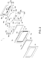
- FIG. 2 is an exploded perspective view of the information display apparatus 1.
- FIG. 3 is an enlarged perspective view of a fixing part 50 of the information display apparatus 1.
- the information display apparatus 1 includes, in an order from the side of a front case 10, a display panel 30, a pair of fixing parts 50, and a circuit substrate 40 inside a housing formed by the front case 10 and a rear case 20.
- the front case 10 has at least two pairs of display panel fixing boss parts 13 (boss parts).
- each of the fixing parts 50 has a strip-like part 51 that is straight, and a pair of branching parts 52 that branch, from a long side 511 of the strip-like part 51, in a direction intersecting with a longitudinal direction of the strip-like part 51.
- branching parts 52 an end part provided with a step difference with respect to the strip-like part 51 is formed.
- each of the strip-like parts 51 are screwed to each pair of the display panel fixing boss parts 13. Accordingly, the display panel 30 is sandwiched and fixed between the pair of fixing parts 50 and the front case 10.
- the circuit substrate 40 is screwed to each of the two pairs of branching parts 52. Accordingly, the circuit substrate 40 is fixed to the pair of fixing parts 50.
- an information display apparatus in which the weight can be reduced, and the respective main components (the front case 10, the display panel 30, the fixing parts 50, and the circuit substrate 40) are firmly fixed to each other can be realized.
- the information display apparatus 1 verifies the operation and the setting content of each apparatus in a factory automation (FA) system and is suitable as a human machine interface (HMI) for inputting various setting contents to each apparatus in the FA system.
- HMI human machine interface
- the information display apparatus 1, as an example of such HMI displaying a display image indicating the operation and the setting content of each apparatus by using the display panel 30 and receiving a touch operation from a user by using a touch panel 60 is described.
- the information display apparatus 1 includes the front case 10, the rear case 20, the display panel 30, the circuit substrate 40, the pair of fixing parts 50, the touch panel 60, and a front sheet 70.
- the side where the front case 10 is located is the front
- the side where the rear case 20 is located is the rear
- the left side when facing the rear is the left
- the right side when facing the rear is the right.
- the front case 10 has a frame part 11 formed to surround a rectangular opening, and a rising part 12 rising rearward from the outer edge of the frame part 11.
- a concave part for insertion of the touch panel 60 to be described afterwards is formed on the front surface of the frame part 11.
- two pairs of display panel fixing boss parts 13a to 13d protruding rearward are provided on the back surface of the frame part 11.
- the pair of display panel fixing boss parts 13a and 13c are provided on the top and the bottom of the left end of the frame part 11 from the center.
- the pair of display panel fixing boss parts 13b and 13d are provided on the top and the bottom of the right end of the frame part 11 from the center.
- a screw hole for insertion of a screw 81 is formed forward from a protruding direction end part.
- these components are simply referred to as the display penal fixing boss parts 13. The same applies to other components in pair.
- the rear case 20 has a bottom part 21, rising parts 22 respectively rising forward from the outer edges of the upper end and the lower end of the bottom part 21, and end parts 23 respectively extending upward and downward from the front ends of the rising parts 22.
- the front case 10 and the rear case 20 are components forming the housing of the information display apparatus 1.
- the front case 10 and the rear case 20 are, for example, connected by screwing hole parts (not shown) provided at the end parts 23 and boss parts (not shown) provided on the back surface of the frame part 11, so that the end parts 23 are brought into contact with the inner surface of the rising part 12.
- the display panel 30 is disposed behind the front case 10 inside the housing formed by the front case 10 and the rear case 20.
- the display panel 30, for example, is a liquid crystal display (LCD), an organic electro-luminescence (EL) display panel, etc.
- each of the fixing parts 50 has the strip-like part 51 that is straight, and the pair of branching parts 52 that branch, from the long side 511 of the strip-like part 51, in a direction intersecting with the longitudinal direction of the strip-like part 51.
- end parts provided with step differences with respect to the strip-like part 51 are formed.
- the branching part 52 has a first extension part 521, a second extension part 522 (step difference), and a third extension part 523 (end part) (see FIG. 3 ).
- the first extension part 521 extends substantially in parallel with the main surface of the strip-like part 51 from the long side 511.
- the second extension part 522 extends rearward from the tip of the first extension part 521.
- the third extension part 523 extends substantially in parallel with the main surface of the strip-like part 51 from the tip of the second extension part 522.
- strip-like part side hole parts 53 are provided at two end parts of the strip-like part 51.
- branching part side hole parts 54 are provided at the pair of branching parts 52 (third extension parts 523).
- the fixing part 50 may also be formed by bending a sheet-like member (e.g., a sheet metal member).
- the two end parts of the strip-like part 51 are screwed to the display panel fixing boss parts 13 by the screws 81. Accordingly, the display panel 30 is sandwiched and fixed between the pair of fixing parts 50 and the front case 10.
- a cushion material for filling a gap between the display panel 30 and the front case 10 may also be attached to the front surface of the display panel 30 and/or the back surface of the frame part 11. Accordingly, the pressure from the pair of fixing parts 50 with respect to the display panel 30 can be suppressed. In addition, the rattling of the display panel 30 due to the gap can be reduced, and the display panel 30 can be firmly fixed.
- the pair of fixing parts 50 include a fixing part 50a disposed on the left and a fixing part 50b disposed on the right.
- Strip-like side hole parts 53a and 53c respectively screwed to the display panel fixing boss parts 13a and 13c are provided at the upper end and the lower end of the strip-like part 51a in the fixing part 50a.
- Strip-like side hole parts 53b and 53d respectively screwed to the display panel fixing boss parts 13b and 13d are provided at the upper end and the lower end of the strip-like part 51b in the fixing part 50b.
- Screws 81a to 81d respectively pass through the strip-like part side hole parts 53a to 53d and fastened to the screw holes of the two pairs of display panel fixing boss parts 13a to 13d.
- the circuit substrate 40 is provided behind the pair of fixing parts 50 to be described afterwards inside the housing formed by the front case 10 and the rear case 20.
- the circuit substrate 40 is rectangular, and includes electronic components on the front surface.
- the four corners of the circuit substrate 40 are respectively provided with four circuit substrate fixing hole parts 44a to 44d.
- the circuit substrate fixing hole parts 44a and 44b are respectively provided at the left end and the right end on the upper side of the circuit substrate 40.
- the circuit substrate fixing hole parts 44c and 44d are respectively provided at the left end and the right end on the lower side of the circuit substrate 40.
- the circuit substrate fixing hole parts 44 are screwed to the branching parts 52 by screws 82. Accordingly, the circuit substrate 40 is fixed to the fixing parts 50.
- the circuit substrate fixing hole parts 44a and 44c are respectively screwed to the branching part side hole parts 54a and 54c provided at the pair of branching parts 52a and 52c respectively branching from the upper end and the lower end of the fixing part 50a.
- the circuit substrate fixing hole parts 44b and 44d are respectively screwed to the branching part side hole parts 54b and 54d provided at the pair of branching parts 52b and 52d respectively branching from the upper end and the lower end of the fixing part 50b.
- Screws 82a to 82d are respectively inserted into the circuit substrate fixing hole parts 44a to 44d and the branching part side hole parts 54a to 54d and fastened through a conventional process.
- the touch panel 60 is fit into the concave part formed on the front surface of the frame part 11.
- the front sheet 70 is attached to the front surface of the frame part 11 to protect the touch panel 60.
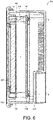
- FIG. 6 is a cross-sectional view illustrating the information display apparatus 101 according to a comparative example at a cross-section orthogonal to the left-right direction.
- FIG. 7 is an enlarged perspective view of a fixing part 150 of the information display apparatus 101 according to the comparative example.
- the information display apparatus 101 includes, in an order from the side of a front case 110, a display panel 130, a fixing part 150, and a circuit substrate 140 inside a housing formed by the front case 110 and a rear case 120.
- a display panel fixing boss part 113 provided at the front case 110 and a display panel fixing hole part 153 provided at the fixing part 150 are screwed (see also FIG. 7 ). Accordingly, the display panel 130 is sandwiched and fixed between the fixing part 150 and the front case 110.
- a circuit substrate fixing boss part 116 provided at the front case 110 and a circuit substrate fixing hole part 146 provided at the circuit substrate 140 are screwed. Accordingly, in the information display apparatus 101 of the comparative example, a configuration in which the circuit substrate 140 is directly and firmly fixed to the front case 110 can be formed.
- the circuit substrate fixing boss part 116 is provided on the outer periphery side with respect to the display panel 130 to protrude toward the circuit substrate 140. That is, the location (area A surrounded by the dot line of FIG. 6 ) where the front case 110 and the circuit substrate 140 are screwed needs to be located on the outer periphery side with respect to the display panel 130. Therefore, in order to cover the screwed location, it is necessary to form the rear case 120 in a box shape without a sense of slimness, and the appearance of the information display apparatus 101 is less preferable.
- FIG. 4 is a cross-sectional view illustrating the information display apparatus 1 and taken along a cross-sectional line A shown in FIG. 1 .
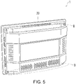
- FIG. 5 is a back view of the information display apparatus 1.
- the branching parts 52 for fixing the circuit substrate 40 is provided, in place of the circuit substrate fixing boss part 116 (see FIG. 6 ) according to the comparative example, at the fixing parts 50. That is, the circuit substrate 40 is fixed to the fixing parts 50 by inserting and fastening the screws 82 to the circuit substrate fixing hole parts 44 and the branching part side hole parts 54.
- the places where the fixing parts 50 and the circuit substrate 40 are screwed are provided on the inner side with respect to the places (the places of the display panel fixing boss parts 13) where the fixing parts 50 and the front case 10 are screwed in the upper-lower direction of the housing. Therefore, the upper-lower width at the bottom part 21 of the rear case 20 covering the circuit substrate 40 from the rear can be reduced with respect to the upper-lower width in the frame part 11 of the front case 10 having the display panel fixing boss parts 13. This means that, compared with the box-shaped rear case 120 (see FIG.
- the upper and lower end parts (areas B surrounded by dot lines in FIGs. 4 and 5 ) of the rear case 20 according to the embodiment can be slim. That is, by applying the fixing parts 50 serving to fix the circuit substrate 40, the size of the housing of the information display apparatus 1 can be reduced.
- the fixing parts 50 according to the embodiment are a pair of strip-like brackets each having the strip-like part 51 that is straight and the pair of branching parts 52. Therefore, compared with the sheet-like bracket covering the display panel as used in the conventional information display apparatus, the weight of the fixing parts 50 can be reduced.
- the strip-like parts 51 of the pair of fixing parts 50 are respectively screwed to the display panel fixing boss parts 13 provided at the top and the bottom of the front case 10. Therefore, the display panel 30 can be effectively pressed down and firmly fixed.
- the circuit substrate 40 are directly screwed at four places. Therefore, the circuit substrate 40 can be indirectly and firmly fixed to the front case 10. Therefore, the information display apparatus 1 in which the weight can be reduced, and the respective main components (the front case 10, the display panel 30, the fixing parts 50, and the circuit substrate 40) are firmly fixed to each other can be realized.
- the third extension parts 523 are located behind the strip-like parts 51.
- the fixing parts 50 have four strip-like part side holes 53a to 53d and four branching part side holes 54a to 54d is described.
- the numbers of the strip-like part side holes 53 and the branching part side holes 54 are not limited thereto.
- the numbers of the display panel fixing boss parts 13 and the circuit substrate fixing hole parts 44 may also be respectively changed.
Landscapes
- Engineering & Computer Science (AREA)
- Physics & Mathematics (AREA)
- Theoretical Computer Science (AREA)
- General Physics & Mathematics (AREA)
- Nonlinear Science (AREA)
- Computer Hardware Design (AREA)
- General Engineering & Computer Science (AREA)
- Crystallography & Structural Chemistry (AREA)
- Chemical & Material Sciences (AREA)
- Human Computer Interaction (AREA)
- Optics & Photonics (AREA)
- Mathematical Physics (AREA)
- Microelectronics & Electronic Packaging (AREA)
- Devices For Indicating Variable Information By Combining Individual Elements (AREA)
Abstract
Description
- The invention relates to an information display apparatus.
- Conventionally, an information display apparatus including, in an order from the front case side, a display panel, a fixing part (fixing bracket), and a circuit substrate inside a housing formed by a front case and a rear case is known. Here, with the fixing part being connected with the front case, the display panel provided between the fixing part and the front case is sandwiched and fixed. In such information display apparatus, a configuration in which the display panel can be firmly fixed with respect to the front case by screwing the fixing part to a boss provided on the front case is known (Patent Document 1).
- In addition, a configuration in which the circuit substrate can be firmly fixed to the fixing part by screwing the circuit substrate to the fixing part is also known (Patent Document 2).
-
- [Patent Document 1]:
Japanese Laid-open No. 2002-215061 - [Patent Document 2]:
Japanese Laid-open No. 2013-190585 - However, the fixing part used in the conventional information display apparatus is a sheet-like bracket covering the display panel. Therefore, the information display apparatus is heavy.
- An aspect of the invention is made in view of the above issue, and an objective thereof is to be able to realize an information display apparatus in which the weight can be reduced and the respective main components are firmly fixed to each other.
- In order to solve the above issue, an information display apparatus according to an aspect of the invention includes: a front case; a rear case, connected with the front case; and a display panel, a pair of fixing parts, and a circuit substrate provided inside a housing formed by the front case and the rear case. The display panel is disposed behind the front case, the pair of fixing parts are disposed behind the display panel, and the circuit substrate is disposed behind the fixing parts. Each of the fixing parts has: a strip-like part that is straight; and a pair of branching parts, which branch from a long side of the strip-like part in a direction intersecting with a longitudinal direction of the strip-like part and in which end parts provided with step differences with respect to the strip-like part are formed. Two end parts of each of the strip-like parts are respectively screwed to the front case, thereby sandwiching and fixing the display panel between the pair of fixing parts and the front case. The circuit substrate is fixed to the fixing parts by being screwed to the two pairs of branching parts respectively.
- According to the configuration, the fixing parts are a pair of strip-like brackets each having the strip-like part that is straight and the pair of branching parts. Therefore, compared with the sheet-like bracket covering the display panel as used in the conventional information display apparatus, the weight of the fixing parts can be reduced. In addition, the strip-like parts of the pair of fixing parts are respectively screwed to the front case. Therefore, the display panel can be fixed between the front case and the fixing parts. In addition, by contacting the branching parts of the fixing parts firmly fixed to the front case, the circuit substrate are directly screwed at four places. Therefore, the circuit substrate can be indirectly fixed to the front case. Therefore, the information display apparatus in which the weight can be reduced, and the respective main components (the front case, the display panel, the fixing parts, and the circuit substrate) are fixed to each other can be realized.
- In addition, the two end parts of the strip-like part may be screwed in a direction toward the front case. According to the configuration, the strip-like parts of the pair of fixing parts are respectively screwed toward the front case. Therefore, the display panel can be effectively pressed down and firmly fixed. Moreover, by contacting the branching parts of the fixing parts firmly fixed to the front case, the circuit substrate are directly screwed at four places. Therefore, the circuit substrate can be indirectly and firmly fixed to the front case. Therefore, the information display apparatus in which the weight can be reduced, and the respective main components (the front case, the display panel, the fixing parts, and the circuit substrate) are firmly fixed to each other can be realized.
- In addition, the front case may have at least two pairs of boss parts, and the two end parts of each of the strip-like parts may be respectively screwed to one pair of the boss parts. According to the configuration, with a simple configuration in which the boss parts are provided at the front case, the display panel can be firmly fixed between the display panel and the fixing part.
- In addition, the fixing part may also be formed by bending a sheet-like member. According to the configuration, by processing to bend the sheet-like member, the fixing part in a strip-like shape having the pair of branching parts can be easily manufactured.
- According to an aspect of the invention, an information display apparatus in which the weight can be reduced and the respective main components are firmly fixed to each other can be realized.
-
-
FIG. 1 is a front view illustrating an information display apparatus according to an embodiment of the invention. -
FIG. 2 is an exploded perspective view of the information display apparatus. -
FIG. 3 is an enlarged perspective view of a fixing part of the information display apparatus. -
FIG. 4 is a cross-sectional view illustrating the information display apparatus and taken along a cross-sectional line A shown inFIG. 1 . -
FIG. 5 is a back view of the information display apparatus. -
FIG. 6 is a cross-sectional view illustrating an information display apparatus according to a comparative example at a cross-section orthogonal to the left-right direction. -
FIG. 7 is an enlarged perspective view of a fixing part of the information display apparatus according to the comparative example. - In the following, an embodiment (referred to as "the embodiment" in the following) according to an aspect of the invention is described with reference to the drawings. However, the embodiment described below is merely an example of the invention in all respects. Various improvements and modifications can be made without departing from the scope of the invention. That is, in carrying out the invention, a specific configuration according to the embodiment may be adopted as appropriate.
-
FIG. 1 is a front view illustrating aninformation display apparatus 1 according to an embodiment of the invention.FIG. 2 is an exploded perspective view of theinformation display apparatus 1.FIG. 3 is an enlarged perspective view of afixing part 50 of theinformation display apparatus 1. As shown inFIGs. 1 and2 , theinformation display apparatus 1 includes, in an order from the side of afront case 10, adisplay panel 30, a pair offixing parts 50, and acircuit substrate 40 inside a housing formed by thefront case 10 and arear case 20. Thefront case 10 has at least two pairs of display panel fixing boss parts 13 (boss parts). - As shown in
FIG. 3 , each of thefixing parts 50 has a strip-like part 51 that is straight, and a pair ofbranching parts 52 that branch, from along side 511 of the strip-like part 51, in a direction intersecting with a longitudinal direction of the strip-like part 51. In each of the branchingparts 52, an end part provided with a step difference with respect to the strip-like part 51 is formed. - The two end parts of each of the strip-
like parts 51 are screwed to each pair of the display panelfixing boss parts 13. Accordingly, thedisplay panel 30 is sandwiched and fixed between the pair offixing parts 50 and thefront case 10. In addition, thecircuit substrate 40 is screwed to each of the two pairs ofbranching parts 52. Accordingly, thecircuit substrate 40 is fixed to the pair offixing parts 50. - According to the application example, an information display apparatus in which the weight can be reduced, and the respective main components (the
front case 10, thedisplay panel 30, the fixingparts 50, and the circuit substrate 40) are firmly fixed to each other can be realized. - The
information display apparatus 1 according to the embodiment, for example, verifies the operation and the setting content of each apparatus in a factory automation (FA) system and is suitable as a human machine interface (HMI) for inputting various setting contents to each apparatus in the FA system. In the following, theinformation display apparatus 1, as an example of such HMI, displaying a display image indicating the operation and the setting content of each apparatus by using thedisplay panel 30 and receiving a touch operation from a user by using atouch panel 60 is described. - As shown in
FIGs. 1 and2 , theinformation display apparatus 1 includes thefront case 10, therear case 20, thedisplay panel 30, thecircuit substrate 40, the pair of fixingparts 50, thetouch panel 60, and afront sheet 70. In the following, in theinformation display apparatus 1, the side where thefront case 10 is located is the front, the side where therear case 20 is located is the rear, the left side when facing the rear is the left, and the right side when facing the rear is the right. - The
front case 10 has aframe part 11 formed to surround a rectangular opening, and a rising part 12 rising rearward from the outer edge of theframe part 11. A concave part for insertion of thetouch panel 60 to be described afterwards is formed on the front surface of theframe part 11. In addition, two pairs of display panel fixingboss parts 13a to 13d protruding rearward are provided on the back surface of theframe part 11. Specifically, the pair of display panel fixingboss parts frame part 11 from the center. In addition, the pair of display panel fixingboss parts frame part 11 from the center. At the display panel fixingboss part 13, a screw hole for insertion of a screw 81 is formed forward from a protruding direction end part. In the specification, when it is not necessary to specifically distinguish the two pairs of display panel fixingboss parts 13a to 13d, these components are simply referred to as the display penal fixingboss parts 13. The same applies to other components in pair. - The
rear case 20 has abottom part 21, risingparts 22 respectively rising forward from the outer edges of the upper end and the lower end of thebottom part 21, and endparts 23 respectively extending upward and downward from the front ends of the risingparts 22. Thefront case 10 and therear case 20 are components forming the housing of theinformation display apparatus 1. Thefront case 10 and therear case 20 are, for example, connected by screwing hole parts (not shown) provided at theend parts 23 and boss parts (not shown) provided on the back surface of theframe part 11, so that theend parts 23 are brought into contact with the inner surface of the rising part 12. - The
display panel 30 is disposed behind thefront case 10 inside the housing formed by thefront case 10 and therear case 20. Thedisplay panel 30, for example, is a liquid crystal display (LCD), an organic electro-luminescence (EL) display panel, etc. - The pair of fixing
parts 50 are provided behind thedisplay panel 30 inside the housing formed by thefront case 10 and therear case 20. As shown inFIGs. 2 and3 , each of the fixingparts 50 has the strip-like part 51 that is straight, and the pair of branchingparts 52 that branch, from thelong side 511 of the strip-like part 51, in a direction intersecting with the longitudinal direction of the strip-like part 51. In one pair of branchingparts 52, end parts provided with step differences with respect to the strip-like part 51 are formed. For example, the branchingpart 52 has afirst extension part 521, a second extension part 522 (step difference), and a third extension part 523 (end part) (seeFIG. 3 ). Thefirst extension part 521 extends substantially in parallel with the main surface of the strip-like part 51 from thelong side 511. Thesecond extension part 522 extends rearward from the tip of thefirst extension part 521. Thethird extension part 523 extends substantially in parallel with the main surface of the strip-like part 51 from the tip of thesecond extension part 522. In addition, strip-like partside hole parts 53 are provided at two end parts of the strip-like part 51. In addition, branching partside hole parts 54 are provided at the pair of branching parts 52 (third extension parts 523). The fixingpart 50 may also be formed by bending a sheet-like member (e.g., a sheet metal member). - The two end parts of the strip-
like part 51 are screwed to the display panel fixingboss parts 13 by the screws 81. Accordingly, thedisplay panel 30 is sandwiched and fixed between the pair of fixingparts 50 and thefront case 10. A cushion material for filling a gap between thedisplay panel 30 and thefront case 10 may also be attached to the front surface of thedisplay panel 30 and/or the back surface of theframe part 11. Accordingly, the pressure from the pair of fixingparts 50 with respect to thedisplay panel 30 can be suppressed. In addition, the rattling of thedisplay panel 30 due to the gap can be reduced, and thedisplay panel 30 can be firmly fixed. - As an example shown in
FIG. 2 , the pair of fixingparts 50 include a fixing part 50a disposed on the left and a fixingpart 50b disposed on the right. Strip-likeside hole parts boss parts parts 53b and 53d respectively screwed to the display panel fixingboss parts like part 51b in the fixingpart 50b.Screws 81a to 81d respectively pass through the strip-like partside hole parts 53a to 53d and fastened to the screw holes of the two pairs of display panel fixingboss parts 13a to 13d. - The
circuit substrate 40 is provided behind the pair of fixingparts 50 to be described afterwards inside the housing formed by thefront case 10 and therear case 20. Thecircuit substrate 40 is rectangular, and includes electronic components on the front surface. The four corners of thecircuit substrate 40 are respectively provided with four circuit substrate fixinghole parts 44a to 44d. Specifically, the circuit substrate fixinghole parts circuit substrate 40. In addition, the circuit substrate fixinghole parts circuit substrate 40. - The circuit substrate fixing
hole parts 44 are screwed to the branchingparts 52 byscrews 82. Accordingly, thecircuit substrate 40 is fixed to the fixingparts 50. As an example inFIG. 2 , the circuit substrate fixinghole parts side hole parts parts hole parts side hole parts parts 52b and 52d respectively branching from the upper end and the lower end of the fixingpart 50b.Screws 82a to 82d are respectively inserted into the circuit substrate fixinghole parts 44a to 44d and the branching partside hole parts 54a to 54d and fastened through a conventional process. - The
touch panel 60 is fit into the concave part formed on the front surface of theframe part 11. In addition, thefront sheet 70 is attached to the front surface of theframe part 11 to protect thetouch panel 60. - In the following, a configuration of an
information display apparatus 101 according to the comparative example is described with reference toFIGs. 6 and7 .FIG. 6 is a cross-sectional view illustrating theinformation display apparatus 101 according to a comparative example at a cross-section orthogonal to the left-right direction.FIG. 7 is an enlarged perspective view of a fixingpart 150 of theinformation display apparatus 101 according to the comparative example. As shown inFIG. 6 , theinformation display apparatus 101 includes, in an order from the side of afront case 110, adisplay panel 130, a fixingpart 150, and acircuit substrate 140 inside a housing formed by thefront case 110 and arear case 120. A display panel fixingboss part 113 provided at thefront case 110 and a display panel fixinghole part 153 provided at the fixingpart 150 are screwed (see alsoFIG. 7 ). Accordingly, thedisplay panel 130 is sandwiched and fixed between the fixingpart 150 and thefront case 110. In addition, a circuit substrate fixingboss part 116 provided at thefront case 110 and a circuit substrate fixinghole part 146 provided at thecircuit substrate 140 are screwed. Accordingly, in theinformation display apparatus 101 of the comparative example, a configuration in which thecircuit substrate 140 is directly and firmly fixed to thefront case 110 can be formed. - Here, the circuit substrate fixing
boss part 116 is provided on the outer periphery side with respect to thedisplay panel 130 to protrude toward thecircuit substrate 140. That is, the location (area A surrounded by the dot line ofFIG. 6 ) where thefront case 110 and thecircuit substrate 140 are screwed needs to be located on the outer periphery side with respect to thedisplay panel 130. Therefore, in order to cover the screwed location, it is necessary to form therear case 120 in a box shape without a sense of slimness, and the appearance of theinformation display apparatus 101 is less preferable. -
FIG. 4 is a cross-sectional view illustrating theinformation display apparatus 1 and taken along a cross-sectional line A shown inFIG. 1 .FIG. 5 is a back view of theinformation display apparatus 1. As shown inFIG. 4 , in theinformation display apparatus 1 according to the embodiment, the branchingparts 52 for fixing thecircuit substrate 40 is provided, in place of the circuit substrate fixing boss part 116 (seeFIG. 6 ) according to the comparative example, at the fixingparts 50. That is, thecircuit substrate 40 is fixed to the fixingparts 50 by inserting and fastening thescrews 82 to the circuit substrate fixinghole parts 44 and the branching partside hole parts 54. - Here, it is not necessary to consider the location of the
display panel 30 for the places where the fixingparts 50 and thecircuit substrate 40 are screwed. Therefore, the places where the fixingparts 50 and thecircuit substrate 40 are screwed are provided on the inner side with respect to the places (the places of the display panel fixing boss parts 13) where the fixingparts 50 and thefront case 10 are screwed in the upper-lower direction of the housing. Therefore, the upper-lower width at thebottom part 21 of therear case 20 covering thecircuit substrate 40 from the rear can be reduced with respect to the upper-lower width in theframe part 11 of thefront case 10 having the display panel fixingboss parts 13. This means that, compared with the box-shaped rear case 120 (seeFIG. 6 ) according to the comparative example, the upper and lower end parts (areas B surrounded by dot lines inFIGs. 4 and5 ) of therear case 20 according to the embodiment can be slim. That is, by applying the fixingparts 50 serving to fix thecircuit substrate 40, the size of the housing of theinformation display apparatus 1 can be reduced. - In addition, the fixing
parts 50 according to the embodiment are a pair of strip-like brackets each having the strip-like part 51 that is straight and the pair of branchingparts 52. Therefore, compared with the sheet-like bracket covering the display panel as used in the conventional information display apparatus, the weight of the fixingparts 50 can be reduced. In addition, the strip-like parts 51 of the pair of fixingparts 50 are respectively screwed to the display panel fixingboss parts 13 provided at the top and the bottom of thefront case 10. Therefore, thedisplay panel 30 can be effectively pressed down and firmly fixed. In addition, by contacting thethird extension parts 523 of the fixingparts 50 firmly fixed to thefront case 10, thecircuit substrate 40 are directly screwed at four places. Therefore, thecircuit substrate 40 can be indirectly and firmly fixed to thefront case 10. Therefore, theinformation display apparatus 1 in which the weight can be reduced, and the respective main components (thefront case 10, thedisplay panel 30, the fixingparts 50, and the circuit substrate 40) are firmly fixed to each other can be realized. - In addition, since step differences are formed at the branching
parts 52, thethird extension parts 523 are located behind the strip-like parts 51. Thus, by screwing the fixingparts 50 to thefront case 10 and thecircuit substrate 40, a space considering the height of the electronic components mounted on thecircuit substrate 40 and the influences of the heat generated by the electronic components can be easily ensured between thedisplay panel 30 and thecircuit substrate 40. - In the embodiment, an example in which the fixing
parts 50 have four strip-likepart side holes 53a to 53d and four branchingpart side holes 54a to 54d is described. However, the numbers of the strip-like part side holes 53 and the branching part side holes 54 are not limited thereto. In addition, in correspondence with the numbers of the strip-like part side holes 53 and the branching part side holes 54, the numbers of the display panel fixingboss parts 13 and the circuit substrate fixinghole parts 44 may also be respectively changed. - The invention is not limited to the above-described embodiments, and various modifications can be made within the scope of the claims. The technical scope of the invention also includes embodiments obtained by appropriately combining the technical means disclosed in the different embodiments.
-
- 1: Information display apparatus;
- 10: Front case;
- 13: Display panel fixing boss part;
- 20: Rear case;
- 30: Display panel;
- 40: Circuit substrate;
- 50: Fixing part;
- 51: Strip-like part;
- 52: Branching part.
Claims (4)
- An information display apparatus (1), comprising:a front case (10);a rear case (20), connected with the front case (10); anda display panel (30), a pair of fixing parts (50), and a circuit substrate (40) provided inside a housing formed by the front case (10) and the rear case (20),wherein the display panel (30) is disposed behind the front case (10),the pair of fixing parts (50) are disposed behind the display panel (30), andthe circuit substrate (40) is disposed behind the fixing parts (50),wherein each of the fixing parts (50) has:a strip-like part (51) that is straight; anda pair of branching parts (52), which branch from a long side (511) of the strip-like part (51) in a direction intersecting with a longitudinal direction of the strip-like part (51) and in which end parts provided with step differences with respect to the strip-like part (51) are formed,wherein two end parts of each of the strip-like parts (51) are respectively screwed to the front case (10), thereby sandwiching and fixing the display panel (30) between the pair of fixing parts (50) and the front case (10), andthe circuit substrate (40) is fixed to the pair of fixing parts (50) by being screwed to the two pairs of branching parts (52) respectively.
- The information display apparatus (1) as claimed in claim 1, wherein the two end parts of the strip-like part (51) are screwed in a direction toward the front case (10).
- The information display apparatus (1) as claimed in claim 2, wherein the front case (10) has at least two pairs of boss parts (13), and
the two end parts of each of the strip-like parts (51) are respectively screwed to one pair of the boss parts (13). - The information display apparatus (1) as claimed in any one of claims 1 to 3, wherein the fixing part (50) is formed by bending a sheet-like member.
Applications Claiming Priority (1)
| Application Number | Priority Date | Filing Date | Title |
|---|---|---|---|
| JP2021112181A JP7687091B2 (en) | 2021-07-06 | 2021-07-06 | information display device |
Publications (1)
| Publication Number | Publication Date |
|---|---|
| EP4116958A1 true EP4116958A1 (en) | 2023-01-11 |
Family
ID=82703094
Family Applications (1)
| Application Number | Title | Priority Date | Filing Date |
|---|---|---|---|
| EP22178810.2A Pending EP4116958A1 (en) | 2021-07-06 | 2022-06-14 | Information display apparatus |
Country Status (4)
| Country | Link |
|---|---|
| US (1) | US11800651B2 (en) |
| EP (1) | EP4116958A1 (en) |
| JP (1) | JP7687091B2 (en) |
| CN (1) | CN115586668A (en) |
Citations (4)
| Publication number | Priority date | Publication date | Assignee | Title |
|---|---|---|---|---|
| JP2002215061A (en) | 2000-12-27 | 2002-07-31 | Samsung Electronics Co Ltd | Display device |
| US20130235277A1 (en) * | 2010-11-29 | 2013-09-12 | Sharp Kabushiki Kaisha | Display device and television receiver |
| JP2013190585A (en) | 2012-03-13 | 2013-09-26 | Panasonic Corp | Liquid crystal display device |
| US9915980B2 (en) * | 2013-04-16 | 2018-03-13 | Samsung Electronics Co., Ltd | Electronic device and assembly structure thereof |
Family Cites Families (14)
| Publication number | Priority date | Publication date | Assignee | Title |
|---|---|---|---|---|
| JP3431447B2 (en) * | 1997-04-16 | 2003-07-28 | シャープ株式会社 | Display device |
| JP5048188B2 (en) * | 2001-06-28 | 2012-10-17 | アイホン株式会社 | Liquid crystal panel conductive connection structure |
| KR100633074B1 (en) * | 2005-03-08 | 2006-10-12 | 삼성전자주식회사 | Display device |
| JP2006259225A (en) * | 2005-03-17 | 2006-09-28 | Orion Denki Kk | Liquid crystal display device with lcd cover |
| KR100741091B1 (en) * | 2005-12-06 | 2007-07-19 | 삼성에스디아이 주식회사 | Plasma display module |
| CN2909316Y (en) * | 2006-04-28 | 2007-06-06 | 鸿富锦精密工业(深圳)有限公司 | Liquid crystal display |
| US8023260B2 (en) * | 2007-09-04 | 2011-09-20 | Apple Inc. | Assembly of an electronic device |
| CN102736681A (en) * | 2011-04-08 | 2012-10-17 | 鸿富锦精密工业(深圳)有限公司 | Installation support and electron device employing therewith |
| JP5447449B2 (en) * | 2011-08-01 | 2014-03-19 | 船井電機株式会社 | Display device |
| KR20140110539A (en) * | 2013-03-08 | 2014-09-17 | 삼성디스플레이 주식회사 | Display apparatus |
| CN104571318B (en) * | 2014-12-05 | 2018-02-23 | 英业达科技有限公司 | Electronic installation and its fixed module |
| CN206741843U (en) * | 2017-05-26 | 2017-12-12 | 董英 | Display |
| US12040532B2 (en) * | 2020-06-25 | 2024-07-16 | Getac Holdings Corporation | Electronic device and antenna assembly |
| DE112020001194B4 (en) * | 2020-10-12 | 2023-11-16 | Denso Ten Limited | Liquid crystal display device and assembly method for a liquid crystal display device |
-
2021
- 2021-07-06 JP JP2021112181A patent/JP7687091B2/en active Active
-
2022
- 2022-06-02 CN CN202210619835.XA patent/CN115586668A/en active Pending
- 2022-06-10 US US17/837,036 patent/US11800651B2/en active Active
- 2022-06-14 EP EP22178810.2A patent/EP4116958A1/en active Pending
Patent Citations (4)
| Publication number | Priority date | Publication date | Assignee | Title |
|---|---|---|---|---|
| JP2002215061A (en) | 2000-12-27 | 2002-07-31 | Samsung Electronics Co Ltd | Display device |
| US20130235277A1 (en) * | 2010-11-29 | 2013-09-12 | Sharp Kabushiki Kaisha | Display device and television receiver |
| JP2013190585A (en) | 2012-03-13 | 2013-09-26 | Panasonic Corp | Liquid crystal display device |
| US9915980B2 (en) * | 2013-04-16 | 2018-03-13 | Samsung Electronics Co., Ltd | Electronic device and assembly structure thereof |
Also Published As
| Publication number | Publication date |
|---|---|
| US11800651B2 (en) | 2023-10-24 |
| US20230009886A1 (en) | 2023-01-12 |
| JP2023008539A (en) | 2023-01-19 |
| JP7687091B2 (en) | 2025-06-03 |
| CN115586668A (en) | 2023-01-10 |
Similar Documents
| Publication | Publication Date | Title |
|---|---|---|
| EP2083313B1 (en) | Liquid crystal module | |
| EP1569066A2 (en) | Electronic apparatus having battery receptable at the rear of keyboard | |
| US20090051662A1 (en) | Touch-Sensitive Screen With Haptic Acknowledgement | |
| EP2456198A1 (en) | Display device comprising an infrared sensor | |
| CN107346640A (en) | Display device | |
| EP3236453A1 (en) | Display device | |
| EP2042914A2 (en) | Bezel attachment scheme for a liquid crystal display module | |
| EP4116958A1 (en) | Information display apparatus | |
| JP2002328622A (en) | Display device and electronic device having the display device | |
| JP2020184005A (en) | Display device | |
| JP3696210B2 (en) | Electronics | |
| JP7057151B2 (en) | Product data processing device | |
| US8811036B2 (en) | Electronic device and frame member | |
| EP2818737A1 (en) | Hinge and electrical appliance | |
| EP2381333A2 (en) | Display device | |
| EP3683621B1 (en) | Display device | |
| JP6698144B1 (en) | Electronics | |
| EP2166428B1 (en) | Stand attachment structure | |
| JP6474222B2 (en) | Video display device | |
| US20080144297A1 (en) | Structure for mounting board | |
| JP6787229B2 (en) | Display device mounting structure on the vehicle display device unit | |
| JP5232292B2 (en) | Electronics | |
| JP2014192515A (en) | Substrate wiring structure | |
| JP6955185B1 (en) | Display device and display device member | |
| JP2021117331A (en) | Display device |
Legal Events
| Date | Code | Title | Description |
|---|---|---|---|
| PUAI | Public reference made under article 153(3) epc to a published international application that has entered the european phase |
Free format text: ORIGINAL CODE: 0009012 |
|
| STAA | Information on the status of an ep patent application or granted ep patent |
Free format text: STATUS: THE APPLICATION HAS BEEN PUBLISHED |
|
| AK | Designated contracting states |
Kind code of ref document: A1 Designated state(s): AL AT BE BG CH CY CZ DE DK EE ES FI FR GB GR HR HU IE IS IT LI LT LU LV MC MK MT NL NO PL PT RO RS SE SI SK SM TR |
|
| STAA | Information on the status of an ep patent application or granted ep patent |
Free format text: STATUS: REQUEST FOR EXAMINATION WAS MADE |
|
| 17P | Request for examination filed |
Effective date: 20230315 |
|
| RBV | Designated contracting states (corrected) |
Designated state(s): AL AT BE BG CH CY CZ DE DK EE ES FI FR GB GR HR HU IE IS IT LI LT LU LV MC MK MT NL NO PL PT RO RS SE SI SK SM TR |
|
| STAA | Information on the status of an ep patent application or granted ep patent |
Free format text: STATUS: EXAMINATION IS IN PROGRESS |
|
| 17Q | First examination report despatched |
Effective date: 20240724 |