EP4116654A1 - Refrigeration appliance - Google Patents
Refrigeration appliance Download PDFInfo
- Publication number
- EP4116654A1 EP4116654A1 EP21184695.1A EP21184695A EP4116654A1 EP 4116654 A1 EP4116654 A1 EP 4116654A1 EP 21184695 A EP21184695 A EP 21184695A EP 4116654 A1 EP4116654 A1 EP 4116654A1
- Authority
- EP
- European Patent Office
- Prior art keywords
- chamber
- chamber wall
- refrigeration appliance
- appliance
- wall
- Prior art date
- Legal status (The legal status is an assumption and is not a legal conclusion. Google has not performed a legal analysis and makes no representation as to the accuracy of the status listed.)
- Pending
Links
Images


Classifications
-
- F—MECHANICAL ENGINEERING; LIGHTING; HEATING; WEAPONS; BLASTING
- F25—REFRIGERATION OR COOLING; COMBINED HEATING AND REFRIGERATION SYSTEMS; HEAT PUMP SYSTEMS; MANUFACTURE OR STORAGE OF ICE; LIQUEFACTION SOLIDIFICATION OF GASES
- F25D—REFRIGERATORS; COLD ROOMS; ICE-BOXES; COOLING OR FREEZING APPARATUS NOT OTHERWISE PROVIDED FOR
- F25D29/00—Arrangement or mounting of control or safety devices
- F25D29/006—Safety devices
-
- F—MECHANICAL ENGINEERING; LIGHTING; HEATING; WEAPONS; BLASTING
- F25—REFRIGERATION OR COOLING; COMBINED HEATING AND REFRIGERATION SYSTEMS; HEAT PUMP SYSTEMS; MANUFACTURE OR STORAGE OF ICE; LIQUEFACTION SOLIDIFICATION OF GASES
- F25D—REFRIGERATORS; COLD ROOMS; ICE-BOXES; COOLING OR FREEZING APPARATUS NOT OTHERWISE PROVIDED FOR
- F25D23/00—General constructional features
- F25D23/006—General constructional features for mounting refrigerating machinery components
-
- F—MECHANICAL ENGINEERING; LIGHTING; HEATING; WEAPONS; BLASTING
- F25—REFRIGERATION OR COOLING; COMBINED HEATING AND REFRIGERATION SYSTEMS; HEAT PUMP SYSTEMS; MANUFACTURE OR STORAGE OF ICE; LIQUEFACTION SOLIDIFICATION OF GASES
- F25D—REFRIGERATORS; COLD ROOMS; ICE-BOXES; COOLING OR FREEZING APPARATUS NOT OTHERWISE PROVIDED FOR
- F25D23/00—General constructional features
- F25D23/06—Walls
- F25D23/065—Details
-
- F—MECHANICAL ENGINEERING; LIGHTING; HEATING; WEAPONS; BLASTING
- F25—REFRIGERATION OR COOLING; COMBINED HEATING AND REFRIGERATION SYSTEMS; HEAT PUMP SYSTEMS; MANUFACTURE OR STORAGE OF ICE; LIQUEFACTION SOLIDIFICATION OF GASES
- F25D—REFRIGERATORS; COLD ROOMS; ICE-BOXES; COOLING OR FREEZING APPARATUS NOT OTHERWISE PROVIDED FOR
- F25D2201/00—Insulation
- F25D2201/10—Insulation with respect to heat
Definitions
- the present invention relates to a refrigeration appliance, in particular to a refrigeration appliance provided with a working chamber receiving components for the functioning of the appliance.
- refrigeration appliances are extensively used, in particular refrigeration appliances for domestic use.
- domestic refrigeration appliances comprising one or more compartments, for example fresh food compartments and/or freezer compartments, for the storage of food and/or beverages.
- a refrigeration appliance typically comprises a parallelepiped-shaped outer cabinet apt to place the refrigerator in a standing working position and an inner liner, disposed within the outer cabinet, which defines said one or more compartments.
- the inner liner typically comprises a single plastic body opportunely shaped to define said one or more compartments or, in alternative known embodiments, two or more inner liners defines respective compartments.
- the space defined between the outer cabinet and the inner liner(s) is advantageously filled with a thermal insulation material, preferably a foam insulation material, to thermally insulate the compartment(s) from the external environment.
- a thermal insulation material preferably a foam insulation material
- the refrigeration is then equipped with a refrigeration system apt to cool the compartments and preferably comprises an electric motor-driven compressor, a condenser heat exchanger, a capillary tube, an evaporator and a fan for creating a cooling air stream for the compartment/s.
- Part of the components of the refrigeration system are preferably arranged in a proper chamber of the refrigerator, or working chamber.
- the working chamber and components contained therein are preferably arranged on the bottom of the cabinet at its back side.
- a particular focus in manufacturing of refrigerators relates the more effective design to meet the most demanding safety requirements in terms of fire protection.
- a drawback of the known system is, in fact, the high flammability of said foam materials used in the refrigeration as thermal insulated material.
- the most critical area subjected to a potential risk of fire is the working chamber containing the compressor or other electric components which represent critical heat-generating devices.
- appliances are subjected to high-quality standards relating fire risk and have to comply with various directives and regulations.
- Another drawback of the known solutions lies in that one or more working chamber wall are in contact with the insulating foam materials and the accidental firing of the chamber wall would trigger fire of the foam, and then of the whole refrigerator cabinet.
- One object of the present invention is therefore to overcome the limits posed by the known techniques.
- a refrigeration appliance having an outer cabinet, a working chamber apt to receive at least one component for the functioning of appliance and at least one chamber wall at least partially delimiting said working chamber, wherein said at least one chamber wall comprises at least a shield portion made of self-extinguishing plastic (or polymeric) material, it is possible to avoid, or at least mitigate, the risk of firing of the whole outer cabinet of the appliance.
- a refrigeration appliance comprising:
- the shield portion of the base support prevents that fire reaches the foam material in case of fire, then avoiding the flammability whole cabinet.
- the self-extinguishing plastic material is a material that satisfies testing standard in accordance with IEC 60695-11-20 - Method 5VA.
- the self-extinguishing plastic material is a flame retardant polypropylene compound, more preferably the product Dafnelen ® CR 09/K marketed by SIRMAX ® (Italy).
- said at least one chamber wall is totally made of self-extinguishing plastic material so that the shield portion coincides with the at least one chamber wall.
- manufacturing process of the chamber wall is simplified, for example by the realization of the chamber wall with the same material during a single injection moulding process.
- the shield portion is defined by an insert element of said at least one chamber wall.
- a dedicated self-extinguishing material is used inside the chamber wall only where needed.
- the material of said at least one chamber wall, except the insert element is a plastic material, preferably a plastic single body.
- the plastic material is a polypropylene copolymer, more preferably the product SKYPLEN ® code 4KC08.
- the working chamber is arranged at a bottom part of the appliance and said at least one chamber wall defines a base support for the appliance.
- the foam material is arranged between the base support and the inner liner.
- the foam material comprises a thermal insulating material, preferably a fast reaction polyurethane (POLYOL+ISOCYANATE).
- a thermal insulating material preferably a fast reaction polyurethane (POLYOL+ISOCYANATE).
- the outer cabinet comprises at least one lateral side wall that extends from a front side to a rear side of the appliance.
- the foam material is arranged between said at least one lateral side wall and said at least one chamber wall.
- said at least one lateral side wall at least partially laterally covers said at least one chamber wall, preferably said at least one lateral side wall entirely laterally covers said at least one chamber wall.
- the lateral side wall confers a protection of the external environment against firing inside the working chamber.
- said at least one lateral side wall is realized in a non-flammable material, preferably in a metal material, more preferably made of iron or aluminium.
- the lateral side wall enhances said protection of the external environment.
- said at least one chamber wall further comprises one or more supporting legs extending downwardly for placement of the appliance on a floor, preferably one or more supporting adjustable levelling supporting legs.
- the working chamber is arranged on the back side of the appliance.
- said at least one lateral side wall comprises two lateral side walls facing each other and said at least one chamber wall comprises two chamber walls facing each other and associated to a respective lateral side wall, said two chamber walls at least partially laterally delimiting the working chamber.
- a cross bar connects the two chamber walls.
- the refrigeration appliance further comprises a supporting element arranged in the lower part of the working chamber.
- working chamber a chamber containing at least an electric component and/or a refrigerating system component which allow the working of the refrigeration appliance; preferably, said component, when working, can potentially trigger a fire inside the working chamber.
- the refrigeration appliance according to the present invention has proved to be particularly advantageous when refers to a refrigeration appliance for domestic use. It should in any case be underlined that the present invention is not limited to this particular embodiment. On the contrary, the present invention conveniently refers to any refrigeration appliance being provided with a working chamber wherein components for the functioning of the refrigeration appliance are arranged.
- Figures 1 and 2 show a refrigeration appliance 1, or refrigerator 1, according to a preferred embodiment of the invention.
- the refrigerator 1 shown in the figures is a refrigerator 1 in the form of a domestic refrigerator, also known as compact refrigerator.
- the refrigerator 1 also preferably refers to a built-in solution.
- the refrigerator according to the invention can have any desired configuration, for example a top mount or a bottom mount refrigerator wherein a freezer compartment and a fresh food compartment are disposed vertically one the other, preferably closed with two respective doors.
- the refrigerator 1 preferably comprises a fresh food compartment 10 ( Figure 4 ).
- a refrigeration system (not shown) is preferably provided to cool the compartment 10, more preferably the refrigeration system is apt to cool down air which is circulated inside the compartment 10.
- the refrigeration system preferably comprises components configured to generate said cooling air flow.
- the refrigeration system preferably comprises a closed recirculating system filled with a suitable refrigerant, for example R12 or R134a.
- the refrigeration system preferably comprises an electric motor-driven compressor, a condenser heat exchanger, a pressure device such as a capillary tube or a thermostatic valve and an evaporator, which eventually define said components (not shown).
- a fan is also preferably used to circulate the cooled air inside the compartment 10.
- the refrigerator 1 preferably comprises an outer cabinet 2 and an inner liner 6, internally received in the outer cabinet 2.
- the inner liner 6 preferably defines said fresh food compartment 10 ( Figure 4 ).
- a door 15 is preferably pivotally mounted to the outer cabinet 2 and is movable between an open position and a closed position to cover the fresh food compartment 10.
- the compartment 10 is preferably provided with support shelves and/or drawers (not shown).
- the inner liner 6 preferably has a substantially parallelepiped shape and further comprises a lower storage space 12 for receiving, preferably, fresh fruits and vegetables.
- the lower storage space 12 preferably has a trapezoidal shape, as visible in Figure 4 .
- the inner liner 6 is preferably made of a polymeric plastic material, such as PS (polystyrene).
- the outer cabinet 2 is preferably parallelepiped-shaped and preferably comprises side walls 2A, 2B, 2C, 2D, preferably two lateral side walls 2A, 2B, a rear side wall 2C and a top side wall 2D.
- lateral side walls 2A, 2B and the rear side wall 2C are preferably aligned to a vertical direction.
- the lateral side walls 2A, 2B (left side wall 2A and right side wall 2B) preferably extend from the front side to the rear side of the refrigerator 1.
- the side walls 2A, 2B, 2C, 2D are realized in a non-flammable material, preferably in a metal material, more preferably made of iron or aluminium.
- a shaped panel 22 is preferably arranged at the lower part of the refrigerator 1 and preferably substantially follows the shape of the lower storage space 12, i.e. a trapezoidal shape.
- the shaped panel 22 is also preferably realized in a non-flammable material, preferably in a metal material, more preferably made of iron or aluminium.
- the shaped panel 22 preferably has a rear side 22A which terminate inwardly with respect to the rear side wall 2C of the outer cabinet 2, as visible in Figure 2 , to define a chamber 20, or working chamber 20.
- the working chamber 20 is thus preferably arranged at the back side of the refrigerator 1 and preferably at a bottom part of the rear side wall 2C.
- the working chamber 20 preferably receives some components of the refrigeration system, for example the compressor and the capillary tube (not shown in the figures).
- the working chamber 20 receives at least an electric component and/or a refrigerating system component which allow the working of the refrigerator 1; preferably, said component, when working, can potentially trigger a fire inside the working chamber 20.
- the refrigerator 1 then preferably comprises at least one base support 30, 32 arranged at its lower side.
- two base supports 30, 32 facing each other and preferably aligned with respective lateral side walls 2A, 2B. More preferably, a first base support 30, or left support 30, is aligned to, and substantially arranged below, the left side wall 2A and a second base support 32, or right support 32, is aligned to, and substantially arranged below, the right side wall 2B.
- the two base supports 30, 32 are preferably fixedly connected to respective lateral side walls 2A, 2B.
- the base supports 30, 32 advantageously support the refrigerator 1 when the latest is positioned in its standing working position.
- the at least one base support 30, 32 at least partially delimits the working chamber 20; more preferably the two base supports 30, 32 at least partially laterally delimit the working chamber 20.
- Each base support 30, 32 therefore, eventually defines a chamber wall at least partially delimiting the working chamber 20.
- the two base supports 30, 32 together with the shaped panel 22 eventually delimit the working chamber 20 and the working chamber 20 is preferably open towards the outside so that it can be conveniently accessible in case of maintenance. Furthermore, dissipation of heat produced by components inside the working chamber 20 is enhanced, in particular heat produced by the compressor.
- each base support 30, 32 comprises a first portion 40, 42 and a second portion 44, 46.
- the first portion 40, 42 is placed at the rear side of the refrigerator 1 and laterally delimits the working chamber 20.
- the second portion 44, 46 is preferably configured to laterally abuts against a respective lateral edge 23A, 24A of the shaped panel 22.
- the second portion 44, 46 of the base support 30, 32 comprises a shaped rib 44A, 46A matching the respective lateral edge 23A, 24A of the shaped panel 22.
- the shaped ribs 44A, 46A and lateral edges 23A, 24A of the shaped panel 22 preferably have a trapezoidal shape. It is clear that in different preferred embodiments, said shapes may be any proper shapes matching each other.
- the base support 30, 32 comprises a single body extending from the front side to the rear side of the refrigerator 1.
- the base support 30, 32 is constituted of a plastic single body, more preferably is moulded via an injection moulding process.
- the base support 30, 32 is made of a polypropylene copolymer, more preferably the product SKYPLEN ® code 4KC08.
- the first/left base support 30 extends, together with the first/left side wall 2A, from the front side to the rear side of the refrigerator 1 and, analogously, the second/right base support 32 extends, together with the second/right side wall 2B, from the front side to the rear side of the refrigerator 1.
- the side wall 2A, 2B partially laterally covers the base support 30, 32 or, in other words, a lower part of the base support 30, 32 is not covered by the side wall 2A, 2B and is exposed directly to the outside.
- the lower part of the base support 30, 32 exposed directly to the outside involves majority of the base support 30, 32.
- the base supports 30, 32 eventually support the refrigerator 1 when the latest is positioned in its standing working position.
- the base supports 30, 32 preferably comprises one or more supporting legs 70 extending downwardly for placement of the refrigerator 1 on the floor.
- two front supporting legs 70 are shown.
- two supporting legs are arranged at the back of the base supports 30, 32.
- the supporting legs are embodied as adjustable levelling supporting legs so that their lengths can be opportunely adjusted when the refrigerator 1 is placed in its standing working position.
- a cross bar 72 then, preferably connects the two base supports 30, 32 ( Figures 3 and 5 ).
- the cross bar 72 is preferably arranged at the rear side of the base supports 30, 32, above the working chamber 20, and transversally connects the same.
- the cross bar 72 is preferably connected with screws to the base supports 30, 32.
- the cross bar 72 advantageously improves stability and stiffness of base supports 30, 32.
- the base supports 30, 32 are opportunely configured to receive a supporting element 74 which is preferably arranged in the lower part of the working chamber 20, preferably to support components inside the working chamber 20 more preferably to support the compressor.
- the supporting element 74 is preferably removably associated to the base supports 30, 32.
- slits 76, 78 are realized at the base supports 30, 32 to slidingly receive lateral sides of the supporting element 74.
- a thermal insulation material is preferably used to externally enclose the inner liner 6 as much as possible. More preferably, a foam insulation material is used during manufacturing of the refrigerator 1 to cover and contact the outer surface of the inner liner 6.
- the foam material preferably comprises a fast reaction polyurethane (POLYOL+ISOCYANATE).
- a foam insulation material is used to fill the space defined between the inner liner 6 and the side walls 2A, 2B, 2C, 2D and the space defined between the lower storage space 12 of the inner liner 6, the shaped panel 22 and the base supports 30, 32.
- the foam insulation material occupies the space delimited by the shaped rib 44A, 46A of the second portion 44, 46 of the base support 30, 32.
- the base support 30, 32 preferably comprises a shield portion 31, 33 made of self-extinguishing plastic (or polymeric) material, wherein the shield portion 31, 33 is arranged in the base support 30, 32 at a position wherein the foam material contacts the base support 30, 32.
- the self-extinguishing plastic material is a material that satisfies testing standard in accordance with IEC 60695-11-20 - Method 5VA.
- the self-extinguishing plastic material is a flame retardant polypropylene compound, more preferably the product Dafnelen ® CR 09/K marketed by SIRMAX ® (Italy).
- the shield portion 31, 33 comprises an insert element 31, 33 associated to the base support 30, 32 wherein the outer contour of the insert element 31, 33 follows the shaped rib 44A, 46A of the second portion 44, 46.
- the foam insulation material that occupies the space delimited by the shaped rib 44A, 46A of the second portion 44, 46 is preferably exclusively in contact with the shield portion 31, 33 of the base support 30, 32 while the other parts of the base support 30, 32 external to the shield portion 31, 33 are not in contact with the foam insulation material.
- the foam material arranged in the space provided between the base support 30, 32 and the inner liner 6, in particular between the base support 30, 32 and the lower storage space 12 of the inner liner 6, is exclusively in contact with the shield portion 31, 33 while the foam material does not contact the other parts of the base support 30, 32 which are not made of self-extinguishing material, i.e. preferably made of other type of plastic materials.
- the shield portion 31, 33 of the base support 30, 32 prevents that fire reaches the foam material in case of fire, in particular in case the base support 30, 32 catches fire.
- foam materials are extremely flammable materials.
- Such an event may be particularly relevant in the refrigerator 1 according to the invention being the working chamber 20 delimited by the base supports 30, 32 and, at the same time, receives the most critical heat-generating device of the refrigerator 1, constituted for example by the compressor or any other component (electrical components and/or refrigerating system components) that can potentially trigger a fire inside the working chamber.
- the shield portion 31, 33 prevents that fire reaches the foam material in case of fire in proximity of the base support 30, 32.
- the base support 30, 32 with its the shield portion 31, 33 improved fire safety requirements of the refrigerator 1 avoiding, or at least mitigating, the risk of firing of the whole outer cabinet 2 of the refrigerator 1. Still advantageously, the self-extinguishing material of the shield portion 31, 33 is used inside the base support 30, 32 only where needed.
- the refrigerator 101 shown in the figures is a stand-alone bottom mount refrigerator 101, i.e. of the type including a freezer compartment 110 disposed vertically below a fresh food compartment 10, as visible in Figure 11 .
- a refrigeration system (not shown) is preferably provided to cool the compartments 10, 110, more preferably the refrigeration system is apt to cool down air which is circulated inside the compartments 10, 110.
- the refrigeration system preferably comprises components configured to generate said cooling air flow.
- the refrigeration system preferably comprises a closed recirculating system filled with a suitable refrigerant, for example R12 or R134a.
- the refrigeration system preferably comprises an electric motor-driven compressor, a condenser heat exchanger, a pressure device such as a capillary tube or a thermostatic valve and an evaporator, which eventually define said components (not shown).
- a fan is also preferably used to circulate the cooled air inside the compartments 10, 110.
- the refrigerator 101 preferably comprises an outer cabinet 2 and an inner liner 106, internally received in the outer cabinet 2.
- the inner liner 106 preferably defines said fresh food compartment 10 and said freezer compartment 110.
- a door 15 is preferably pivotally mounted to the outer cabinet 2 and is movable between an open position and a closed position to cover the fresh food compartment 10 and a door 115 is preferably pivotally mounted to the outer cabinet 2 and is movable between an open position and a closed position to cover the freezer compartment 110.
- the compartments 10, 110 are preferably provided with support shelves and/or drawers (not shown).
- the compartments 10, 110 are defined by the inner liner 106 preferably formed as a one-piece monolithic body.
- the compartments 10, 110 may be defined by respective separated inner liners.
- the compartments 10, 110 have a substantially parallelepiped shape.
- the inner liner 106 is preferably made of a polymeric plastic material, such as PS (polystyrene).
- the outer cabinet 2 is preferably parallelepiped-shaped and preferably comprises side walls 2A, 2B, 2C, 2D, preferably two lateral side walls 2A, 2B, a rear side wall 2C and a top side wall 2D.
- lateral side walls 2A, 2B and the rear side wall 2C are preferably aligned to a vertical direction.
- the lateral side walls 2A, 2B (left side wall 2A and right side wall 2B) preferably extend from the front side to the rear side of the refrigerator 101.
- the side walls 2A, 2B, 2C, 2D are realized in a non-flammable material, preferably in a metal material, more preferably made of iron or aluminium.
- Some of said components of the refrigeration system are preferably arranged in a working chamber 20 of the refrigerator 101.
- the working chamber 20 is preferably arranged at the back side of the refrigerator 101 and preferably at a bottom part of the rear side wall 2C.
- the working chamber 20 is preferably thermally-insulated and/or sound-insulated, in particular thermally-insulated with respect to the freezer compartment 110.
- a shaped panel 122 is preferably interposed between the working chamber 20 and the freezer compartment 110, as depicted in Figure 9 .
- the shaped panel 122 is also preferably realized in a non-flammable material, preferably in a metal material, more preferably made of iron or aluminium.
- the refrigerator 101 then preferably comprises at least one base support 130, 132 arranged at its lower side.
- two base supports 130, 132 facing each other and preferably aligned with respective lateral side walls 2A, 2B. More preferably, a first base support 130, or left support 130, is aligned to, and substantially arranged below, the left side wall 2A and a second base support 132, or right support 132, is aligned to, and substantially arranged below, the right side wall 2B.
- the two base supports 130, 132 are preferably fixedly connected to respective lateral side walls 2A, 2B.
- the base supports 130, 132 advantageously support the refrigerator 101 when the latest is positioned in its standing working position.
- the at least one base support 130, 132 at least partially delimits the working chamber 20; more preferably the two base supports 130, 132 at least partially laterally delimit the working chamber 20.
- Each base support 130, 132 therefore, eventually defines a chamber wall at least partially delimiting the working chamber 20.
- the two base supports 130, 132 together with the shaped panel 122 eventually delimit the working chamber 20 and the working chamber 20 is preferably open towards the outside so that it can be conveniently accessible in case of maintenance. Furthermore, dissipation of heat produced by components inside the working chamber 20 is enhanced, in particular heat produced by the compressor.
- the working chamber 20 is then preferably delimited by the shaped panel 122 in the back-to-front direction while the working chamber 20 is preferably open towards the outside.
- each base support 130, 132 comprises a first portion 140, 142 and a second portion 144, 146.
- the first portion 140, 142 is placed at the rear side of the refrigerator 101 and laterally delimits the working chamber 20.
- the second portion 144, 146 extends towards the front side of the refrigerator 101.
- the base support 130, 132 is preferably configured to laterally abuts against a respective lateral edge 124A of the shaped panel 122.
- the base support 130, 132 comprises a shaped rib 144A, 146A matching the respective lateral edge 124A of the shaped panel 122.
- the base support 130, 132 comprises a single body extending from the front side to the rear side of the refrigerator 101.
- the base support 130, 132 is constituted of a plastic single body, as better described later.
- manufacturing process of the base support 130, 132 is simplified compared to previous embodiment comprising and insert.
- the first/left base support 130 extends, together with the first/left side wall 2A, from the front side to the rear side of the refrigerator 101 and, analogously, the second/right base support 132 extends, together with the second/right side wall 2B, from the front side to the rear side of the refrigerator 101.
- the side wall 2A, 2B entirely laterally covers the base support 130, 132 or, in other words, no one surface of the base support 130, 132 is exposed directly to the outside.
- a solution allows to improve the aesthetic appearance of the refrigerator 101.
- the base support 130, 132 comprises an external surface 150 that faces the respective side wall 2A, 2B of the outer cabinet 2 and hence said external surface 150 is not exposed directly to the outside.
- the lateral side wall 2A, 2B confers a protection of the external environment against firing inside the working chamber 20, in particular when the lateral side wall 2A, 2B is realized in a non-flammable material, preferably in a metal material, more preferably made of iron or aluminium.
- the base supports 130, 132 eventually support the refrigerator 101 when the latest is positioned in its standing working position.
- the base supports 130, 132 preferably comprises one or more supporting legs 170a, 170b, 171a, 171b extending downwardly for placement of the refrigerator 101 on the floor, more preferably a right front leg 170a, a left front leg 171a, a rear right leg 170b and a left rear leg 171b.
- the supporting legs may be embodied as adjustable levelling supporting legs so that their lengths can be opportunely adjusted when the refrigerator 101 is placed in its standing working position.
- a cross bar 72 then, preferably connects the two base supports 130, 132 ( Figure 10 ).
- the cross bar 72 is preferably arranged at the rear side of the base supports 130, 132, above the working chamber 20, and transversally connects the same.
- the cross bar 72 is preferably connected with screws to the base supports 130, 132.
- the cross bar 72 advantageously improves stability and stiffness of base supports 130, 132.
- the base supports 130, 132 are opportunely configured to receive a supporting element 74 which is preferably arranged in the lower part of the working chamber 20, preferably to support components inside the working chamber 20 more preferably to support the compressor.
- the supporting element 74 is preferably removably associated to the base supports 130, 132.
- slits 76, 78 are realized at the base supports 130, 132 to slidingly receive lateral sides of the supporting element 74.
- a thermal insulation material is preferably used to externally enclose the inner liner 106 as much as possible. More preferably, a foam insulation material is used during manufacturing of the refrigerator 101 to cover and contact the outer surface of the inner liner 106.
- the foam material preferably comprises a fast reaction polyurethane (POLYOL+ISOCYANATE).
- a foam insulation material is used to fill the space defined between the inner liner 106 and the side walls 2A, 2B, 2C, 2D.
- the foam insulation material fills the space defined between the side walls 2A, 2B and the base supports 130, 132, more preferably the space between the external surfaces 150, 152 of the base supports 130, 132 and the side walls 2A, 2B.
- the external surfaces 150, 152 of the base supports 130, 132 are therefore in contact with the foam insulation material.
- the base support 130, 132 is totally made of self-extinguishing plastic (or polymeric) material.
- the self-extinguishing plastic material is a material that satisfies testing standard in accordance with IEC 60695-11-20 - Method 5VA.
- the self-extinguishing plastic material is a flame retardant polypropylene compound, more preferably the product Dafnelen ® CR 09/K marketed by SIRMAX ® (Italy).
- the foam material arranged in the space provided between the base support 130, 132 and the inner liner 106 is exclusively in contact with the self-extinguishing plastic material of the base support 130, 132.
- the self-extinguishing plastic material of the base supports 130, 132 prevents that fire reaches the foam material in case of fire, in particular in case the base support 30, 32 catches fire.
- foam materials are extremely flammable materials.
- Such an event may be particularly relevant in the refrigerator 101 according to the invention being the working chamber 20 delimited by the base supports 130, 132 and, at the same time, receiving the most critical heat-generating device of the refrigerator 101 constituted by the compressor.
- the base supports 130, 132 prevents that fire reaches the foam material in case of fire in proximity of the base support 130, 132.
- the present invention allows all the set objects to be achieved.
- the refrigeration appliance of the invention makes it possible to improve fire safety requirements of the appliance compared to known refrigeration appliances.
- the refrigerator according to the first embodiment described above may comprise a base support totally made of self-extinguishing plastic material, i.e. a base support as described for the second embodiment.
- the refrigerator according to the second embodiment may comprise a base support having an insert element made of self-extinguishing plastic material, i.e. a base support as described for the first embodiment.
Abstract
Description
- The present invention relates to a refrigeration appliance, in particular to a refrigeration appliance provided with a working chamber receiving components for the functioning of the appliance.
- Nowadays refrigeration appliances are extensively used, in particular refrigeration appliances for domestic use. We will refer, in particular, to domestic refrigeration appliances comprising one or more compartments, for example fresh food compartments and/or freezer compartments, for the storage of food and/or beverages.
- A refrigeration appliance, hereinafter indicated simply with the term refrigerator, typically comprises a parallelepiped-shaped outer cabinet apt to place the refrigerator in a standing working position and an inner liner, disposed within the outer cabinet, which defines said one or more compartments.
- The inner liner typically comprises a single plastic body opportunely shaped to define said one or more compartments or, in alternative known embodiments, two or more inner liners defines respective compartments.
- The space defined between the outer cabinet and the inner liner(s) is advantageously filled with a thermal insulation material, preferably a foam insulation material, to thermally insulate the compartment(s) from the external environment.
- The refrigeration is then equipped with a refrigeration system apt to cool the compartments and preferably comprises an electric motor-driven compressor, a condenser heat exchanger, a capillary tube, an evaporator and a fan for creating a cooling air stream for the compartment/s.
- Part of the components of the refrigeration system are preferably arranged in a proper chamber of the refrigerator, or working chamber. The working chamber and components contained therein are preferably arranged on the bottom of the cabinet at its back side.
- A particular focus in manufacturing of refrigerators relates the more effective design to meet the most demanding safety requirements in terms of fire protection.
- A drawback of the known system is, in fact, the high flammability of said foam materials used in the refrigeration as thermal insulated material.
- The most critical area subjected to a potential risk of fire is the working chamber containing the compressor or other electric components which represent critical heat-generating devices.
- As known, furthermore, appliances are subjected to high-quality standards relating fire risk and have to comply with various directives and regulations.
- Another drawback of the known solutions lies in that one or more working chamber wall are in contact with the insulating foam materials and the accidental firing of the chamber wall would trigger fire of the foam, and then of the whole refrigerator cabinet.
- One object of the present invention is therefore to overcome the limits posed by the known techniques.
- It is an object of the invention to provide a refrigeration appliance with improved fire safety requirements compared to known systems.
- It is another object of the invention to provide a refrigeration appliance having a cabinet able to avoid the flame propagation throughout the whole cabinet.
- The applicant has found that by providing a refrigeration appliance having an outer cabinet, a working chamber apt to receive at least one component for the functioning of appliance and at least one chamber wall at least partially delimiting said working chamber, wherein said at least one chamber wall comprises at least a shield portion made of self-extinguishing plastic (or polymeric) material, it is possible to avoid, or at least mitigate, the risk of firing of the whole outer cabinet of the appliance.
- According to one aspect of the present disclosure there is provided a refrigeration appliance comprising:
- an outer cabinet and an inner liner, internal to said outer cabinet, defining at least one compartment for the storage of products to be cooled;
- a working chamber apt to receive at least one component for the functioning of said appliance;
- at least one chamber wall at least partially delimiting said working chamber;
- a foam material arranged in a space provided between said at least one chamber wall and said outer cabinet or between said at least one chamber wall and said inner liner;
- Advantageously, the shield portion of the base support prevents that fire reaches the foam material in case of fire, then avoiding the flammability whole cabinet. Preferably, the self-extinguishing plastic material is a material that satisfies testing standard in accordance with IEC 60695-11-20 - Method 5VA. Preferably, the self-extinguishing plastic material is a flame retardant polypropylene compound, more preferably the product Dafnelen® CR 09/K marketed by SIRMAX® (Italy).
- Preferably, said at least one chamber wall is totally made of self-extinguishing plastic material so that the shield portion coincides with the at least one chamber wall.
- Advantageously, manufacturing process of the chamber wall is simplified, for example by the realization of the chamber wall with the same material during a single injection moulding process.
- In a preferred embodiment, the shield portion is defined by an insert element of said at least one chamber wall.
- Advantageously, a dedicated self-extinguishing material is used inside the chamber wall only where needed.
- According to a preferred embodiment of the invention, the material of said at least one chamber wall, except the insert element, is a plastic material, preferably a plastic single body.
- Preferably, the plastic material is a polypropylene copolymer, more preferably the product SKYPLEN® code 4KC08.
- In a preferred embodiment, the working chamber is arranged at a bottom part of the appliance and said at least one chamber wall defines a base support for the appliance.
- According to a preferred embodiment of the invention, the foam material is arranged between the base support and the inner liner.
- Preferably, the foam material comprises a thermal insulating material, preferably a fast reaction polyurethane (POLYOL+ISOCYANATE).
- In a preferred embodiment, the outer cabinet comprises at least one lateral side wall that extends from a front side to a rear side of the appliance.
- According to a preferred embodiment of the invention, the foam material is arranged between said at least one lateral side wall and said at least one chamber wall.
- Preferably, said at least one lateral side wall at least partially laterally covers said at least one chamber wall, preferably said at least one lateral side wall entirely laterally covers said at least one chamber wall.
- Advantageously, the lateral side wall confers a protection of the external environment against firing inside the working chamber.
- Preferably, said at least one lateral side wall is realized in a non-flammable material, preferably in a metal material, more preferably made of iron or aluminium. Advantageously, the lateral side wall enhances said protection of the external environment.
- In a preferred embodiment, said at least one chamber wall further comprises one or more supporting legs extending downwardly for placement of the appliance on a floor, preferably one or more supporting adjustable levelling supporting legs. According to a preferred embodiment of the invention, the working chamber is arranged on the back side of the appliance.
- Preferably, said at least one lateral side wall comprises two lateral side walls facing each other and said at least one chamber wall comprises two chamber walls facing each other and associated to a respective lateral side wall, said two chamber walls at least partially laterally delimiting the working chamber.
- In a preferred embodiment, a cross bar connects the two chamber walls. According to a preferred embodiment of the invention, the refrigeration appliance further comprises a supporting element arranged in the lower part of the working chamber.
- Generally, with working chamber it is meant a chamber containing at least an electric component and/or a refrigerating system component which allow the working of the refrigeration appliance; preferably, said component, when working, can potentially trigger a fire inside the working chamber.
- Further characteristics and advantages of the present invention will be highlighted in greater detail in the following detailed description of preferred embodiments of the invention, provided with reference to the enclosed drawings. In such drawings:
-
Figure 1 shows a front perspective view of a refrigeration appliance according to a preferred embodiment of the invention; -
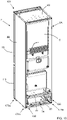
Figure 2 shows a rear perspective view of the appliance ofFigure 1 ; -
Figure 3 shows the appliance ofFigure 2 with some elements removed therefrom; -
Figure 4 shows an exploded view ofFigure 1 ; -
Figure 5 shows a partial exploded view of a detail ofFigure 3 ; -
Figure 6 shows an exploded view of elements ofFigure 3 isolated from the rest; -
Figure 7 shows the elements ofFigure 6 from another point of view; -
Figure 8 shows an enlarged view of a detail ofFigure 6 ; -
Figure 8 shows a front perspective view of a refrigeration appliance according to a further preferred embodiment of the invention; -
Figure 9 shows a rear perspective view of the appliance ofFigure 8 ; -
Figure 10 shows the appliance ofFigure 9 with some elements removed therefrom; -
Figure 11 shows an exploded view ofFigure 8 ; -
Figure 12 shows an exploded view of a detail ofFigure 10 ; -
Figure 13 shows an enlarged detail ofFigure 12 ; -
Figure 14 shows an element ofFigure 13 from another point of view. - The refrigeration appliance according to the present invention has proved to be particularly advantageous when refers to a refrigeration appliance for domestic use. It should in any case be underlined that the present invention is not limited to this particular embodiment. On the contrary, the present invention conveniently refers to any refrigeration appliance being provided with a working chamber wherein components for the functioning of the refrigeration appliance are arranged.
-
Figures 1 and2 show arefrigeration appliance 1, orrefrigerator 1, according to a preferred embodiment of the invention. - The
refrigerator 1 shown in the figures is arefrigerator 1 in the form of a domestic refrigerator, also known as compact refrigerator. Therefrigerator 1 also preferably refers to a built-in solution. - However, the refrigerator according to the invention can have any desired configuration, for example a top mount or a bottom mount refrigerator wherein a freezer compartment and a fresh food compartment are disposed vertically one the other, preferably closed with two respective doors.
- Furthermore, a stand-alone solution may be contemplated rather than a built-in solution.
- The
refrigerator 1 according to the first preferred embodiment illustrated and described herein preferably comprises a fresh food compartment 10 (Figure 4 ). A refrigeration system (not shown) is preferably provided to cool thecompartment 10, more preferably the refrigeration system is apt to cool down air which is circulated inside thecompartment 10. - The refrigeration system preferably comprises components configured to generate said cooling air flow. The refrigeration system preferably comprises a closed recirculating system filled with a suitable refrigerant, for example R12 or R134a. The refrigeration system preferably comprises an electric motor-driven compressor, a condenser heat exchanger, a pressure device such as a capillary tube or a thermostatic valve and an evaporator, which eventually define said components (not shown). A fan is also preferably used to circulate the cooled air inside the
compartment 10. - The
refrigerator 1 preferably comprises anouter cabinet 2 and aninner liner 6, internally received in theouter cabinet 2. Theinner liner 6 preferably defines said fresh food compartment 10 (Figure 4 ). - A
door 15 is preferably pivotally mounted to theouter cabinet 2 and is movable between an open position and a closed position to cover thefresh food compartment 10. Thecompartment 10 is preferably provided with support shelves and/or drawers (not shown). - According to the first preferred embodiment shown in the figures, the
inner liner 6 preferably has a substantially parallelepiped shape and further comprises alower storage space 12 for receiving, preferably, fresh fruits and veggies. - The
lower storage space 12 preferably has a trapezoidal shape, as visible inFigure 4 . - The
inner liner 6 is preferably made of a polymeric plastic material, such as PS (polystyrene). - The
outer cabinet 2 is preferably parallelepiped-shaped and preferably comprisesside walls lateral side walls rear side wall 2C and atop side wall 2D. - In its standing working position,
lateral side walls rear side wall 2C are preferably aligned to a vertical direction. - The
lateral side walls left side wall 2A andright side wall 2B) preferably extend from the front side to the rear side of therefrigerator 1. - Preferably, the
side walls - A shaped
panel 22 is preferably arranged at the lower part of therefrigerator 1 and preferably substantially follows the shape of thelower storage space 12, i.e. a trapezoidal shape. The shapedpanel 22 is also preferably realized in a non-flammable material, preferably in a metal material, more preferably made of iron or aluminium. - The shaped
panel 22 preferably has arear side 22A which terminate inwardly with respect to therear side wall 2C of theouter cabinet 2, as visible inFigure 2 , to define achamber 20, or workingchamber 20. The workingchamber 20 is thus preferably arranged at the back side of therefrigerator 1 and preferably at a bottom part of therear side wall 2C. - The working
chamber 20 preferably receives some components of the refrigeration system, for example the compressor and the capillary tube (not shown in the figures). - Generally, the working
chamber 20 receives at least an electric component and/or a refrigerating system component which allow the working of therefrigerator 1; preferably, said component, when working, can potentially trigger a fire inside the workingchamber 20. - The
refrigerator 1 then preferably comprises at least onebase support - In the preferred embodiment illustrated herein, there are provided two base supports 30, 32 facing each other and preferably aligned with respective
lateral side walls first base support 30, or leftsupport 30, is aligned to, and substantially arranged below, theleft side wall 2A and asecond base support 32, orright support 32, is aligned to, and substantially arranged below, theright side wall 2B. The two base supports 30, 32 are preferably fixedly connected to respectivelateral side walls - The base supports 30, 32 advantageously support the
refrigerator 1 when the latest is positioned in its standing working position. - Preferably, the at least one
base support chamber 20; more preferably the two base supports 30, 32 at least partially laterally delimit the workingchamber 20. - Each
base support chamber 20. - The two base supports 30, 32 together with the shaped
panel 22 eventually delimit the workingchamber 20 and the workingchamber 20 is preferably open towards the outside so that it can be conveniently accessible in case of maintenance. Furthermore, dissipation of heat produced by components inside the workingchamber 20 is enhanced, in particular heat produced by the compressor. - More preferably, each
base support first portion second portion first portion refrigerator 1 and laterally delimits the workingchamber 20. - The
second portion lateral edge panel 22. In particular, as shown inFigure 4 , thesecond portion base support rib lateral edge panel 22. - In the preferred embodiments illustrated herein, the shaped
ribs lateral edges panel 22 preferably have a trapezoidal shape. It is clear that in different preferred embodiments, said shapes may be any proper shapes matching each other. - Preferably, the
base support refrigerator 1. Preferably, thebase support base support - Preferably, the first/left
base support 30 extends, together with the first/left side wall 2A, from the front side to the rear side of therefrigerator 1 and, analogously, the second/right base support 32 extends, together with the second/right side wall 2B, from the front side to the rear side of therefrigerator 1. Theside wall base support base support side wall figures 1 to 7 , the lower part of thebase support base support - As explained, the base supports 30, 32 eventually support the
refrigerator 1 when the latest is positioned in its standing working position. - At this purpose, the base supports 30, 32 preferably comprises one or more supporting
legs 70 extending downwardly for placement of therefrigerator 1 on the floor. InFigure 1 , two front supportinglegs 70 are shown. Preferably, also two supporting legs (not shown) are arranged at the back of the base supports 30, 32. - In a preferred embodiment, the supporting legs are embodied as adjustable levelling supporting legs so that their lengths can be opportunely adjusted when the
refrigerator 1 is placed in its standing working position. - A
cross bar 72, then, preferably connects the two base supports 30, 32 (Figures 3 and5 ). In the preferred embodiment illustrated in the figures, thecross bar 72 is preferably arranged at the rear side of the base supports 30, 32, above the workingchamber 20, and transversally connects the same. Thecross bar 72 is preferably connected with screws to the base supports 30, 32. - The
cross bar 72 advantageously improves stability and stiffness of base supports 30, 32. - Furthermore, the base supports 30, 32 are opportunely configured to receive a supporting
element 74 which is preferably arranged in the lower part of the workingchamber 20, preferably to support components inside the workingchamber 20 more preferably to support the compressor. - The supporting
element 74 is preferably removably associated to the base supports 30, 32. Preferably, slits 76, 78 are realized at the base supports 30, 32 to slidingly receive lateral sides of the supportingelement 74. - In order to thermally insulate the
compartment 10 from the external environment a thermal insulation material is preferably used to externally enclose theinner liner 6 as much as possible. More preferably, a foam insulation material is used during manufacturing of therefrigerator 1 to cover and contact the outer surface of theinner liner 6. - The foam material preferably comprises a fast reaction polyurethane (POLYOL+ISOCYANATE).
- Preferably, referring to
Figure 4 , a foam insulation material is used to fill the space defined between theinner liner 6 and theside walls lower storage space 12 of theinner liner 6, the shapedpanel 22 and the base supports 30, 32. - More preferably, the foam insulation material occupies the space delimited by the shaped
rib second portion base support - According to an aspect of the invention, the
base support shield portion shield portion base support base support - Preferably, the self-extinguishing plastic material is a material that satisfies testing standard in accordance with IEC 60695-11-20 - Method 5VA. Preferably, the self-extinguishing plastic material is a flame retardant polypropylene compound, more preferably the product Dafnelen® CR 09/K marketed by SIRMAX® (Italy).
- In the preferred embodiment illustrated in the figures, the
shield portion insert element base support insert element rib second portion - The foam insulation material that occupies the space delimited by the shaped
rib second portion shield portion base support base support shield portion - In other words, the foam material arranged in the space provided between the
base support inner liner 6, in particular between thebase support lower storage space 12 of theinner liner 6, is exclusively in contact with theshield portion base support shield portion base support base support - As known, in fact, foam materials are extremely flammable materials.
- Such an event may be particularly relevant in the
refrigerator 1 according to the invention being the workingchamber 20 delimited by the base supports 30, 32 and, at the same time, receives the most critical heat-generating device of therefrigerator 1, constituted for example by the compressor or any other component (electrical components and/or refrigerating system components) that can potentially trigger a fire inside the working chamber. - In general, the
shield portion base support - Advantageously, the
base support shield portion refrigerator 1 avoiding, or at least mitigating, the risk of firing of the wholeouter cabinet 2 of therefrigerator 1. Still advantageously, the self-extinguishing material of theshield portion base support - With reference to
Figures 8 to 14 arefrigerator 101 according to a further preferred embodiment of the invention is described. In the drawings, corresponding characteristics and/or components compared to previous preferred embodiment are identified by the same reference numbers. - The
refrigerator 101 shown in the figures is a stand-alonebottom mount refrigerator 101, i.e. of the type including afreezer compartment 110 disposed vertically below afresh food compartment 10, as visible inFigure 11 . - A refrigeration system (not shown) is preferably provided to cool the
compartments compartments - The refrigeration system preferably comprises components configured to generate said cooling air flow. The refrigeration system preferably comprises a closed recirculating system filled with a suitable refrigerant, for example R12 or R134a. The refrigeration system preferably comprises an electric motor-driven compressor, a condenser heat exchanger, a pressure device such as a capillary tube or a thermostatic valve and an evaporator, which eventually define said components (not shown). A fan is also preferably used to circulate the cooled air inside the
compartments - The
refrigerator 101 preferably comprises anouter cabinet 2 and aninner liner 106, internally received in theouter cabinet 2. Theinner liner 106 preferably defines saidfresh food compartment 10 and saidfreezer compartment 110. - A
door 15 is preferably pivotally mounted to theouter cabinet 2 and is movable between an open position and a closed position to cover thefresh food compartment 10 and adoor 115 is preferably pivotally mounted to theouter cabinet 2 and is movable between an open position and a closed position to cover thefreezer compartment 110. Thecompartments - In the preferred embodiment illustrated and described hereinbelow, the
compartments inner liner 106 preferably formed as a one-piece monolithic body. - In different preferred embodiments, the
compartments - According to this preferred embodiment, the
compartments - The
inner liner 106 is preferably made of a polymeric plastic material, such as PS (polystyrene). - The
outer cabinet 2 is preferably parallelepiped-shaped and preferably comprisesside walls lateral side walls rear side wall 2C and atop side wall 2D. - In its standing working position,
lateral side walls rear side wall 2C are preferably aligned to a vertical direction. - The
lateral side walls left side wall 2A andright side wall 2B) preferably extend from the front side to the rear side of therefrigerator 101. - Preferably, the
side walls - Some of said components of the refrigeration system are preferably arranged in a working
chamber 20 of therefrigerator 101. - The working
chamber 20 is preferably arranged at the back side of therefrigerator 101 and preferably at a bottom part of therear side wall 2C. - The working
chamber 20 is preferably thermally-insulated and/or sound-insulated, in particular thermally-insulated with respect to thefreezer compartment 110. A shapedpanel 122 is preferably interposed between the workingchamber 20 and thefreezer compartment 110, as depicted inFigure 9 . The shapedpanel 122 is also preferably realized in a non-flammable material, preferably in a metal material, more preferably made of iron or aluminium. - The
refrigerator 101 then preferably comprises at least onebase support - In the preferred embodiment illustrated herein, there are provided two base supports 130, 132 facing each other and preferably aligned with respective
lateral side walls first base support 130, or leftsupport 130, is aligned to, and substantially arranged below, theleft side wall 2A and asecond base support 132, orright support 132, is aligned to, and substantially arranged below, theright side wall 2B. The two base supports 130, 132 are preferably fixedly connected to respectivelateral side walls - The base supports 130, 132 advantageously support the
refrigerator 101 when the latest is positioned in its standing working position. - Preferably, the at least one
base support chamber 20; more preferably the two base supports 130, 132 at least partially laterally delimit the workingchamber 20. - Each
base support chamber 20. - The two base supports 130, 132 together with the shaped
panel 122 eventually delimit the workingchamber 20 and the workingchamber 20 is preferably open towards the outside so that it can be conveniently accessible in case of maintenance. Furthermore, dissipation of heat produced by components inside the workingchamber 20 is enhanced, in particular heat produced by the compressor. - The working
chamber 20 is then preferably delimited by the shapedpanel 122 in the back-to-front direction while the workingchamber 20 is preferably open towards the outside. - More preferably, each
base support first portion second portion first portion refrigerator 101 and laterally delimits the workingchamber 20. Thesecond portion refrigerator 101. - The
base support panel 122. In particular, as shown inFigures 11 and13 , thebase support rib panel 122. - Preferably, the
base support refrigerator 101. Preferably, thebase support base support - Preferably, the first/left
base support 130 extends, together with the first/left side wall 2A, from the front side to the rear side of therefrigerator 101 and, analogously, the second/right base support 132 extends, together with the second/right side wall 2B, from the front side to the rear side of therefrigerator 101. - The
side wall base support base support refrigerator 101. - Preferably, the
base support external surface 150 that faces therespective side wall outer cabinet 2 and hence saidexternal surface 150 is not exposed directly to the outside. - Advantageously, the
lateral side wall chamber 20, in particular when thelateral side wall - As explained, the base supports 130, 132 eventually support the
refrigerator 101 when the latest is positioned in its standing working position. - At this purpose, the base supports 130, 132 preferably comprises one or more supporting
legs refrigerator 101 on the floor, more preferably a rightfront leg 170a, a leftfront leg 171a, a rearright leg 170b and a leftrear leg 171b. - In a further preferred embodiment, the supporting legs may be embodied as adjustable levelling supporting legs so that their lengths can be opportunely adjusted when the
refrigerator 101 is placed in its standing working position. - A
cross bar 72, then, preferably connects the two base supports 130, 132 (Figure 10 ). In the preferred embodiment illustrated in the figures, thecross bar 72 is preferably arranged at the rear side of the base supports 130, 132, above the workingchamber 20, and transversally connects the same. Thecross bar 72 is preferably connected with screws to the base supports 130, 132. - The
cross bar 72 advantageously improves stability and stiffness of base supports 130, 132. - Furthermore, the base supports 130, 132 are opportunely configured to receive a supporting
element 74 which is preferably arranged in the lower part of the workingchamber 20, preferably to support components inside the workingchamber 20 more preferably to support the compressor. - The supporting
element 74 is preferably removably associated to the base supports 130, 132. Preferably, slits 76, 78 are realized at the base supports 130, 132 to slidingly receive lateral sides of the supportingelement 74. - In order to thermally insulate the
compartments inner liner 106 as much as possible. More preferably, a foam insulation material is used during manufacturing of therefrigerator 101 to cover and contact the outer surface of theinner liner 106. - The foam material preferably comprises a fast reaction polyurethane (POLYOL+ISOCYANATE).
- Preferably, a foam insulation material is used to fill the space defined between the
inner liner 106 and theside walls - Furthermore, preferably, the foam insulation material fills the space defined between the
side walls external surfaces 150, 152 of the base supports 130, 132 and theside walls external surfaces 150, 152 of the base supports 130, 132 are therefore in contact with the foam insulation material. - According to an aspect of the invention, the
base support - Preferably, the self-extinguishing plastic material is a material that satisfies testing standard in accordance with IEC 60695-11-20 - Method 5VA. Preferably, the self-extinguishing plastic material is a flame retardant polypropylene compound, more preferably the product Dafnelen® CR 09/K marketed by SIRMAX® (Italy).
- Advantageously, the foam material arranged in the space provided between the
base support inner liner 106 is exclusively in contact with the self-extinguishing plastic material of thebase support - According to an advantageous aspect of the invention, the self-extinguishing plastic material of the base supports 130, 132 prevents that fire reaches the foam material in case of fire, in particular in case the
base support - Such an event may be particularly relevant in the
refrigerator 101 according to the invention being the workingchamber 20 delimited by the base supports 130, 132 and, at the same time, receiving the most critical heat-generating device of therefrigerator 101 constituted by the compressor. - In general, the base supports 130, 132 prevents that fire reaches the foam material in case of fire in proximity of the
base support - It has thus been shown that the present invention allows all the set objects to be achieved. In particular, the refrigeration appliance of the invention makes it possible to improve fire safety requirements of the appliance compared to known refrigeration appliances.
- While the present invention has been described with reference to the particular embodiments shown in the figures, it should be noted that the present invention is not limited to the specific embodiments illustrated and described herein; on the contrary, further variants of the embodiments described herein fall within the scope of the present invention, which is defined in the claims.
- For example, the refrigerator according to the first embodiment described above may comprise a base support totally made of self-extinguishing plastic material, i.e. a base support as described for the second embodiment. Vice versa, the refrigerator according to the second embodiment may comprise a base support having an insert element made of self-extinguishing plastic material, i.e. a base support as described for the first embodiment.
Claims (16)
- A refrigeration appliance (1; 101) comprising:- an outer cabinet (2) and an inner liner (6; 106), internal to said outer cabinet (2), defining at least one compartment (10; 110) for the storage of products to be cooled;- a working chamber (20) apt to receive at least one component for the functioning of said appliance (1; 101);- at least one chamber wall (30, 32; 130, 132) at least partially delimiting said working chamber (20);- a foam material arranged in a space provided between said at least one chamber wall (30, 32; 130, 132) and said outer cabinet (2) or between said at least one chamber wall (30, 32; 130, 132) and said inner liner (6; 106);wherein said at least one chamber wall (30, 32; 130, 132) comprises at least a shield portion (31, 33; 130, 132) made of self-extinguishing plastic material, wherein said shield portion (31, 33; 130, 132) is arranged in said at least one chamber wall (30, 32; 130, 132) at a position wherein said foam material contacts said at least one chamber wall (30, 32; 130, 132).
- A refrigeration appliance (101) according to claim 1, wherein said at least one chamber wall (130, 132) is totally made of self-extinguishing plastic material so that said shield portion (130, 132) coincides with said at least one chamber wall (130, 132).
- A refrigeration appliance (1) according to claim 1, wherein said shield portion (31, 33) is defined by an insert element of said at least one chamber wall (30, 32).
- A refrigeration appliance (1; 101) according to claim 3, wherein the material of said at least one chamber wall (30, 32; 130, 132), except said insert element, is a plastic material, preferably a plastic single body, more preferably a polypropylene copolymer.
- A refrigeration appliance (1; 101) according to any of the preceding claims, wherein said self-extinguishing plastic material is a material that satisfies testing standard in accordance with IEC 60695-11-20 - Method 5VA, preferably a flame retardant polypropylene compound.
- A refrigeration appliance (1; 101) according to any of the preceding claims, wherein said working chamber (20) is arranged at a bottom part of said appliance (1; 101) and said at least one chamber wall (30, 32; 130, 132) defines a base support (30, 32; 130, 132) for said appliance (1; 101).
- A refrigeration appliance (1) according to claim 6, wherein said foam material is arranged between said base support (30, 32) and said inner liner (6; 106).
- A refrigeration appliance (1; 101) according to any of the preceding claims, wherein said foam material comprises a thermal insulating material, preferably a fast reaction polyurethane.
- A refrigeration appliance (1; 101) according to any of the preceding claims, wherein said outer cabinet (2) comprising at least one lateral side wall (2A, 2B) that extends from a front side to a rear side of said appliance (1; 101).
- A refrigeration appliance (1; 101) according to claim 9, wherein said foam material is arranged between said at least one lateral side wall (2A, 2B) and said at least one chamber wall (130, 132).
- A refrigeration appliance (1; 101) according to claim 9 or 10, wherein said at least one lateral side wall (2A, 2B) at least partially laterally covers said at least one chamber wall (30, 32; 130, 132), preferably said at least one lateral side wall (2A, 2B) entirely laterally covers said at least one chamber wall (130, 132).
- A refrigeration appliance (1; 101) according to any of the preceding claims, wherein said at least one chamber wall (30, 32; 130, 132) further comprises one or more supporting legs (70; 170a, 170b, 171a, 171b) extending downwardly for placement of said appliance (1; 101) on a floor, preferably one or more supporting adjustable levelling supporting legs (70).
- A refrigeration appliance (1; 101) according to any of the preceding claims, wherein said working chamber (20) is arranged on the back side of said appliance (1; 101).
- A refrigeration appliance (1; 101) according to any of the claims 9 to 11, wherein said at least one lateral side wall (2A, 2B) comprises two lateral side walls (2A, 2B) facing each other and said at least one chamber wall (30, 32; 130, 132) comprises two chamber walls (30, 32; 130, 132) facing each other and associated to a respective lateral side wall (2A, 2B), said two chamber walls (30, 32; 130, 132) at least partially laterally delimiting said working chamber (20).
- A refrigeration appliance (1; 101) according to claim 14, wherein it comprises a cross bar (72) connecting said two chamber walls (30, 32; 130, 132).
- A refrigeration appliance (1; 101) according to any of the preceding claims, wherein it comprises a supporting element (74) arranged in the lower part of said working chamber (20).
Priority Applications (1)
| Application Number | Priority Date | Filing Date | Title |
|---|---|---|---|
| EP21184695.1A EP4116654A1 (en) | 2021-07-09 | 2021-07-09 | Refrigeration appliance |
Applications Claiming Priority (1)
| Application Number | Priority Date | Filing Date | Title |
|---|---|---|---|
| EP21184695.1A EP4116654A1 (en) | 2021-07-09 | 2021-07-09 | Refrigeration appliance |
Publications (1)
| Publication Number | Publication Date |
|---|---|
| EP4116654A1 true EP4116654A1 (en) | 2023-01-11 |
Family
ID=76859455
Family Applications (1)
| Application Number | Title | Priority Date | Filing Date |
|---|---|---|---|
| EP21184695.1A Pending EP4116654A1 (en) | 2021-07-09 | 2021-07-09 | Refrigeration appliance |
Country Status (1)
| Country | Link |
|---|---|
| EP (1) | EP4116654A1 (en) |
Citations (4)
| Publication number | Priority date | Publication date | Assignee | Title |
|---|---|---|---|---|
| US3326832A (en) * | 1963-01-23 | 1967-06-20 | Basf Ag | Self-extinguishing plastics compositions |
| JPH1130474A (en) * | 1997-07-10 | 1999-02-02 | Hoshizaki Electric Co Ltd | Heat-insulating box body structure and manufacturing method |
| JP2003314948A (en) * | 2002-04-18 | 2003-11-06 | Hitachi Home & Life Solutions Inc | Refrigerator |
| JP5123786B2 (en) * | 2007-08-22 | 2013-01-23 | ダブルデイ・アクイジションズ・リミテッド・ライアビリティ・カンパニー | Cargo container for transporting temperature sensitive items |
-
2021
- 2021-07-09 EP EP21184695.1A patent/EP4116654A1/en active Pending
Patent Citations (4)
| Publication number | Priority date | Publication date | Assignee | Title |
|---|---|---|---|---|
| US3326832A (en) * | 1963-01-23 | 1967-06-20 | Basf Ag | Self-extinguishing plastics compositions |
| JPH1130474A (en) * | 1997-07-10 | 1999-02-02 | Hoshizaki Electric Co Ltd | Heat-insulating box body structure and manufacturing method |
| JP2003314948A (en) * | 2002-04-18 | 2003-11-06 | Hitachi Home & Life Solutions Inc | Refrigerator |
| JP5123786B2 (en) * | 2007-08-22 | 2013-01-23 | ダブルデイ・アクイジションズ・リミテッド・ライアビリティ・カンパニー | Cargo container for transporting temperature sensitive items |
Similar Documents
| Publication | Publication Date | Title |
|---|---|---|
| JP2001099552A (en) | Cooler/refrigerator | |
| US8911040B2 (en) | Refrigerator | |
| KR20140119443A (en) | Refrigerator | |
| RU2581735C2 (en) | Household refrigerator | |
| WO2013080477A1 (en) | Refrigerator | |
| EP4116654A1 (en) | Refrigeration appliance | |
| JP2006284172A (en) | Refrigerator | |
| US10520245B2 (en) | Home appliance device and assembly method | |
| JP6035510B2 (en) | refrigerator | |
| JP4004722B2 (en) | refrigerator | |
| JP4552800B2 (en) | refrigerator | |
| EP4116651A1 (en) | Refrigeration appliance | |
| AU2022307734A1 (en) | Refrigeration appliance | |
| JP2007078345A (en) | Refrigerator | |
| KR100193175B1 (en) | Bottom freezer | |
| JP7270955B2 (en) | refrigerator | |
| EP3945270A1 (en) | No-frost refrigerator appliance | |
| JP2019032161A (en) | refrigerator | |
| KR100389736B1 (en) | Refrigerator | |
| US20080011006A1 (en) | Built-in refrigerator with increased internal volume | |
| CN115836185A (en) | Refrigeration appliance | |
| KR20150021827A (en) | Refrigerator | |
| KR200204128Y1 (en) | Door of refrigerator | |
| JP2007064591A (en) | Refrigerator | |
| JP2007040600A (en) | Refrigerator |
Legal Events
| Date | Code | Title | Description |
|---|---|---|---|
| PUAI | Public reference made under article 153(3) epc to a published international application that has entered the european phase |
Free format text: ORIGINAL CODE: 0009012 |
|
| STAA | Information on the status of an ep patent application or granted ep patent |
Free format text: STATUS: THE APPLICATION HAS BEEN PUBLISHED |
|
| AK | Designated contracting states |
Kind code of ref document: A1 Designated state(s): AL AT BE BG CH CY CZ DE DK EE ES FI FR GB GR HR HU IE IS IT LI LT LU LV MC MK MT NL NO PL PT RO RS SE SI SK SM TR |
|
| STAA | Information on the status of an ep patent application or granted ep patent |
Free format text: STATUS: REQUEST FOR EXAMINATION WAS MADE |
|
| 17P | Request for examination filed |
Effective date: 20230711 |
|
| RBV | Designated contracting states (corrected) |
Designated state(s): AL AT BE BG CH CY CZ DE DK EE ES FI FR GB GR HR HU IE IS IT LI LT LU LV MC MK MT NL NO PL PT RO RS SE SI SK SM TR |